Embed Size (px)
Citation preview

Product Review and Short Takes from QST Magazine
August 2012
Product Reviews:
MFJ-994BRT and MFJ-998RT Remote Automatic Antenna Tuners
ICOM ID-31A 70-cm Handheld Transceiver with D-STAR
Short Takes:
iDVM Wireless Multimeter

QST® – Devoted entirely to Amateur Radio www.arrl.org August 2012 47
Technical
by Mark Spencer, WA8SME
MFJ-994BRT and MFJ-998RT Remote Automatic Antenna Tuners
These high power matching networks mount at the antenna.
Product Review
Mark J. Wilson, K1RO, [email protected]
Bottom LineThe MFJ-994BRT and MFJ-998RT
provide reasonably priced remote auto tuner solutions for stations with high power amplifiers.
Reviewed by Phil Salas, AD5XContributing [email protected]
I previously reviewed several remote auto-matic antenna tuners specifically for use with a 43 foot vertical antenna.1 Those remote tuners were limited to about 200 W maximum RF power, unsuitable for stations using power amplifiers. This has now changed with the introduction of the MFJ-994BRT (600 W) and MFJ-998RT (1500 W) remote auto tuners.
A remote antenna tuner must be weather-proof and remotely powered, and it must provide automatic tuning. For a given RF power handling and impedance matching specification, a remote antenna tuner will generally be more expensive than a desktop unit because of these requirements.
With many manual and automatic desktop models available, why use a remote antenna tuner? It’s an efficient way to match an antenna that has a high SWR and is fed through a relatively long length of coaxial cable. SWR-related coax cable losses can be high when the antenna SWR is high — even if an in-shack tuner provides a 1:1 SWR for your equipment. You can easily demonstrate this with antenna modeling software simula-tions and a coax/SWR calculator.
OverviewThe MFJ-994BRT and MFJ-998RT are remote versions of the current MFJ-994B (600 W) and MFJ-998 (1500 W) switched L-network desktop auto tuners.2 Turning these into remote auto tuners involved mounting them in weatherproof boxes and
removing some of the desktop features such as A/B antenna switching and multiple memory banks. A comparison of the MFJ-994BRT and MFJ-998RT auto tuners is given in Table 1.
In addition to the higher RF power ratings, the MFJ-994BRT and MFJ-998RT include some interesting features not found in other remote auto tuners. The first is an internal bias-T for those who may not have dc power available at the antenna. (A bias-T allows you to inject dc into the coax feed line so you don’t have to run a separate power cable.) An MFJ-4117 bias-T for the station end of the feed line is included with both units and it includes an ON/OFF switch for convenient power control of the auto tuners.
The MFJ-994BRT and MFJ-998RT provide SO-239 connectors and random wire out-puts (only one at a time can be used). The SO-239 connector has been tested to more than 2 kV to ensure there is no possibility of arcing under high SWR conditions.
These auto tuners include an LC limit feature that provides upper limits of induc-tance and capacitance according to fre-quency and maximum power rating. This feature limits the MFJ-994BRT maximum peak voltage to 1000 V and maximum peak current to 10 A across these components. For the MFJ-998RT the maximum limits are 2100 V peak and 13 A peak. If a match could be achieved, but with settings that would result in destructive voltages or currents, the auto tuners will not permit the match.
Both auto tuners will not tune if more than
75 W is applied and the SWR is greater than 3:1, or if more than 125 W is applied regard-less of SWR. This effectively locks the tuner settings when high power is applied, protect-ing the tuner and your RF power amplifier from damage.
Finally, both the MFJ-994BRT and the MFJ-998RT can be forced to retune on any given frequency. When Sticky Tune is enabled (default) these auto tuners will always retune the first time you transmit after a power cycle. So if you want to try for a lower tuned SWR on a given frequency, simply cycle power and then transmit on that frequency. The MFJ-994BRT and MFJ-998RT will retune and store the new tuning data for that frequency only. All other previously stored memory locations will be unaffected.
Tuner MeasurementsI performed resistive matching range and loss testing with a precision setup similar to that used in the ARRL Lab.3 This is a good way to systematically check an auto tuner’s ability to match a wide variety of loads.
While resistive matching tests are great for standard antenna tuner comparison testing, remote tuners will experience maximum inductance and highest RF current with short antennas, so antenna tuner losses can be higher under these conditions. To determine auto tuner losses in more real-world condi-tions, I built two antenna simulator circuits. One is based on the tuners’ minimum antenna length specifications for 160 meters. The other simulates the popular 43 foot vertical on 80 meters.
Note that most auto tuners, the MFJ-994BRT and MFJ-998RT included, do not
1P. Salas, AD5X, “Remote Automatic Antenna Tuners and the 43 Foot Vertical,” Product Review, QST, Mar 2010, pp 47-52. Product Reviews mentioned here are available to ARRL members online at www.arrl.org/product-review.
2The MFJ-994, an earlier version of the MFJ-994B, was reviewed in the August 2006 QST.
3J. Parise, W1UK, “QST Reviews Five High-Power Antenna Tuners,” Product Review, QST, Feb 2003, pp 69-75. See the sidebar, “Antenna Tuner Testing Methods vs Accuracy” by Michael Tracy, KC1SX, on p 75.
48 August 2012 ARRL, the national association for Amateur Radio® www.arrl.org
Table 3 shows the results of resistive load tuning range and loss measurements in the ARRL Lab. In most cases the 1.5:1 target specification was met. As with the MFJ-994BRT, the high impedance tuning range is significantly broader than the low impedance range. The low impedance limit is specified at 4:1 SWR.
I measured the MFJ-998RT tuner losses using the 160 and 80 meter short antenna simulator circuits described earlier, again with approximately 10 W of real resistance added to simulate ground losses. The MFJ-998RT was able to match a simulated 43 foot vertical for 80 meters and a simu-lated 90 foot antenna for 160 meters with power loss less than 10% and minimum SWR of 1.2:1 on 80 and 1.6:1 on 160.
Open/Short Circuit TestingIdeally a tuner should not be able to match an open or short circuit load. If it does, this means that it is tuning into its own internal losses. However, no antenna tuner is lossless due to components with finite Q. From past experi-ence I’ve found that most antenna tuners — manual and automatic — can find a match on one or more fre-quencies when connected to an open or a short.
In the ARRL Lab, neither tuner could find a match into an open circuit or a shorted PL-259 connector. At my station, I found some note-worthy short circuit match occurrences. With both the MFJ-994BRT and MFJ-998RT, on 20 meters I found a short circuit match with an SWR less than 2:1. If you have a shorted antenna feed
have enough internal inductance to tune a 43 foot vertical on 160 meters. MFJ offers the MFJ-2904 external inductor assembly that can be manually strapped in line at the auto tuner output to enable 160 meter tuning capability with a 43 foot vertical. In addition, I developed a remotely switched range extender for 160 meter operation and improved 80 meter operation that will be the subject of a future QST article.
For final testing, I connected each auto tuner to the base of my 43 foot vertical and recorded the tuned SWR on different bands. I measured the SWR in my shack with an Array Solutions PowerMaster. Seventy feet of Andrew FSJ4-50B 1⁄2 inch Heliax low loss coax connects my transceiver and amplifier in the shack to the auto tuners at the base of the 43 foot vertical. Three ground rods and approximately 20 radials provide RF and dc grounding at the antenna — certainly not a perfect ground, but probably not atypical. As a reference, I measured the resonant imped-ance of my 43 foot vertical on 60 meters as 48 – j0 W, which implies my ground loss is 12 W on that band.
Details of my test setup are available in the digital edition of QST and online at www.arrl.org/qst-in-depth.
MFJ-994BRT Remote Auto TunerThe MFJ-994BRT, with its 600 W SSB/CW capability, is perfect for the many medium power amplifiers on the market. The photos accompanying Table 2 show the outside of the unit and the internal circuitry. Note that the inductors consist of a mix of toroidal and wide-spaced air-wound inductors.
ARRL Lab test results are given in Table 2. As you can see, the MFJ-994BRT matched all resistive loads presented to it that were within its specified tuning range. And while there were a few cases in which the SWR didn’t reach the 1.5:1 target, in most cases the target specification was met.
I measured the MFJ-994BRT tuner losses using the 160 and 80 meter short antenna simulator circuits described earlier. Approximately 10 W of real resistance was added to simulate ground losses. The MFJ-994BRT was able to match a simulated 43 foot vertical for 80 meters and a simu-lated 100 foot antenna for 160 meters with power loss less than 10% and minimum SWR of 1.3:1 on 80 and 1.7:1 on 160.
MFJ-998RT Remote Auto TunerThe MFJ-998RT handles a full 1500 W PEP on SSB or CW. Construction is similar to the MFJ-994BRT with a mix of toroidal and wide-spaced air-wound inductors.
Table 1 MFJ-994BRT and MFJ-998RT Specifications
MFJ-994BRT MFJ-998RT
Frequency range: 1.8-30 MHz 1.8-30 MHzRF power capability: 600 W CW/SSB 1500 W CW/SSBResistive matching range: 12-800 W 12-1600 WCapacitance range: 0-2950 pF 0-3900 pF (input side) 0-970 pF (output side)Inductance range: 0-17 µH 0-24 µH12-15 V dc current required: 850 mA max 1.4 A maxSize (HWD, approx): 2.8 × 10.1 × 9.2 in. 3.25 × 13.75 × 17 in.Weight: 3.7 lb 9.5 lbPrice: $400 $770
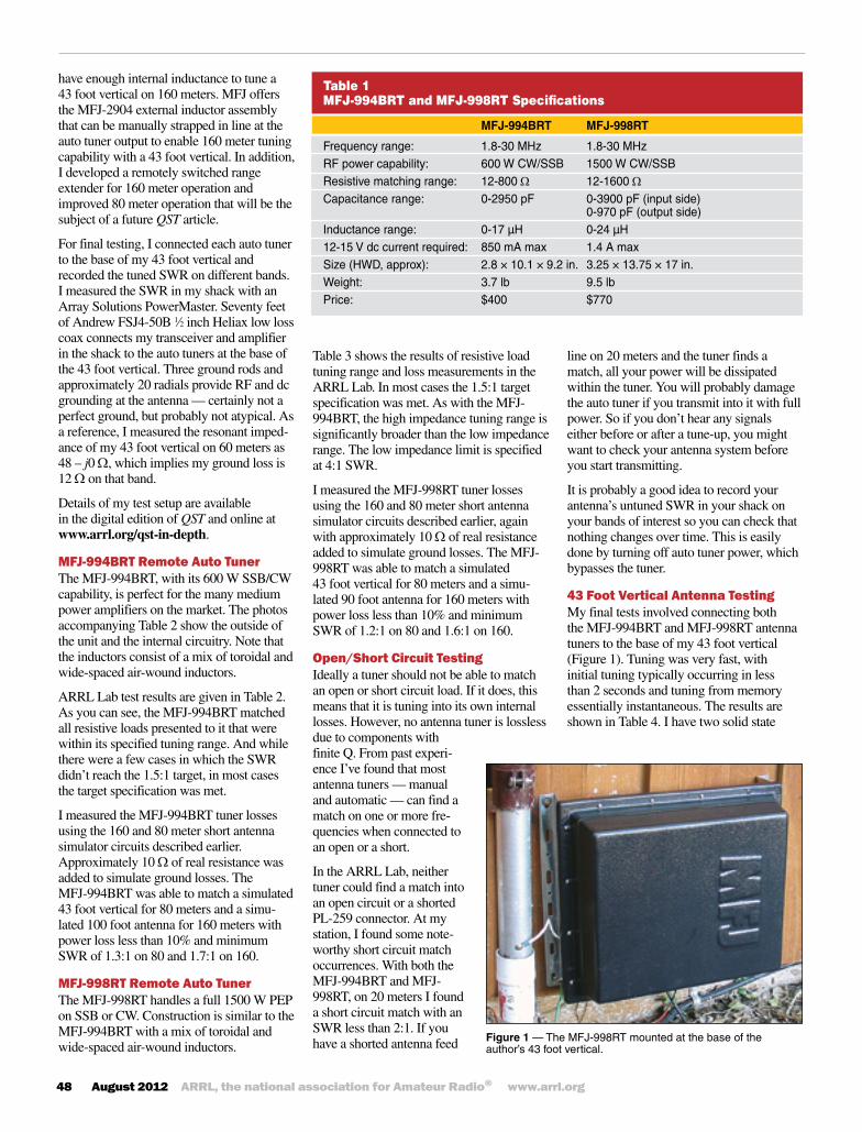
Figure1 — The MFJ-998RT mounted at the base of the author’s 43 foot vertical.
line on 20 meters and the tuner finds a match, all your power will be dissipated within the tuner. You will probably damage the auto tuner if you transmit into it with full power. So if you don’t hear any signals either before or after a tune-up, you might want to check your antenna system before you start transmitting.
It is probably a good idea to record your antenna’s untuned SWR in your shack on your bands of interest so you can check that nothing changes over time. This is easily done by turning off auto tuner power, which bypasses the tuner.
43 Foot Vertical Antenna TestingMy final tests involved connecting both the MFJ-994BRT and MFJ-998RT antenna tuners to the base of my 43 foot vertical (Figure 1). Tuning was very fast, with initial tuning typically occurring in less than 2 seconds and tuning from memory essentially instantaneous. The results are shown in Table 4. I have two solid state

QST® – Devoted entirely to Amateur Radio www.arrl.org August 2012 49
amplifiers — an Ameritron ALS-600 and an Elecraft KPA500. Both amplifiers put out full power into the tuned antenna system on all bands from 80 to 10 meters (I did, of course, limit power to 200 W on 30 meters).
As pointed out in both manuals, I found occurrences in which both auto tuners would not tune when changing bands. This can occur if the tuning solution for the previous band results in a very high SWR on the new band, and more often happens when going from a lower frequency band to a higher frequency band especially when using a highly reactive antenna. This very high SWR can reflect all input power from your transceiver, so the auto tuner cannot sense RF input power. The solution is to simply cycle power to the auto tuner when changing bands. This drops the auto tuner to bypass prior to tuning so some forward power is sensed thus permitting a tune to occur.
On the Air with the Remote Auto TunersEach auto tuner was installed on my 43 foot vertical for about one week. During this time I enjoyed numerous QSOs on 80 through 15 meters primarily using my Elecraft K3 transceiver and KPA500 amplifier. In all cases I would start anew on each band by pressing the TUNE button on my K3 (my K3 TUNE output is set for 15 W) with the ampli-fier off line. It was interesting to watch the PowerMaster SWR readout in the shack as the remote tuners did their thing. Once tuning stopped, usually less than 5 seconds on an initial tune, or instantaneously for a previously memorized tune, I would enable the amplifier and operate with no worries. Changing bands or making large frequency changes within a band required a trivial effort. And I never had an occurrence of either auto tuner trying to tune while operat-ing at high power. It was a very pleasant experience indeed!
SummaryThere are definite benefits to using a remote auto tuner with an untuned antenna. First, of course, is operating convenience. And second, the remote auto tuner will reduce SWR related coax losses. In the past, we have been limited to barefoot operation with the remote auto tuners available. Now, with the introduction of the MFJ-994BRT and MFJ-998RT high power remote auto tuners, we can realize these benefits when using a high power amplifier. The MFJ-994BRT works well with medium-power HF ampli-
Table 2MFJ-994BRT Resistive Load and Loss Testing
Manufacturer’sSpecifications
Matching range: Up to 4:1 for <50 W, up to 16:1 for >50 W.Minimum power for tuning: 2 W. Maximum power for tuning: 20 W (100 W with foldback). Target SWR: 1.5:1 (default) or 2:1 (selectable). Tuning threshold: 0.5 to 1.5 above target SWR, 0.5 default.
ARRLLabTestingSWR Load(W) 160m 80m 40m 20m 10m 4.3:1 11.5 Power Loss (%) * * * * * SWR 1.6 ** ** ** 1.7
2:1 25 Power Loss (%) * * * * * SWR ** ** 1.9 ** **
1:1 50 Power Loss (%) * * * * * SWR ** ** ** ** **
2:1 100 Power Loss (%) * * * * * SWR ** 1.6 1.7 ** 1.6
4:1 200 Power Loss (%) * * * * 14 SWR 1.7 1.7 ** ** 2.0
7.6:1 380 Power Loss (%) * * * * 20 SWR ** ** 1.6 ** **
16:1 800 Power Loss (%) 11 12 * * 28 SWR 2.0 2.0 ** ** 2.0
*Power loss less than or equal to 10%. **Matched SWR less than or equal to 1.5:1. Measured current usage: 2.4 A peak during tuning, 214 mA idle.

50 August 2012 ARRL, the national association for Amateur Radio® www.arrl.org
Manufacturer: MFJ Enterprises, PO Box 494, Mississippi State, MS 39762, tel 800-647-1800; www.mfjenterprises.com.
fiers feeding less than perfect antenna systems. But if you are running more than 600 W or plan to do so in the future, the MFJ-998RT is the way to go.
Product UpdateSince these review units were received, MFJ has improved the design by adding static and lightning protection to both the MFJ-994BRT and MFJ-998RT outputs, and an
Table 4AD5X 43 Foot Vertical Testing
Band Shack ShackSWR ShackSWR SWR withtuning withtuning untuned MFJ-994BRT MFJ-998RT
160 >20:1 NT NT 80 11:1 1.53:1 1.12:1 60 2:1 1.38:1 1.14:1 40 3.8:1 1.21:1 1.32:1 30 6.7:1 1.47:1 1.61:1 20 5.4:1 1.59:1 1.55:1 17 2.5:1 1.39:1 1.42:1 15 4.3:1 1.35:1 1.64:1 12 3.1:1 1.32:1 1.35:1 10 2.3:1 1.06:1 1.27:1NT = no tuning solution (as expected)
Table 3 MFJ-998RT Resistive Load and Loss Testing
Manufacturer’sSpecifications
Matching range: Up to 4:1 for <50 W, up to 32:1 for >50 W.Minimum power for tuning: 5 W. Maximum power for tuning: 20 W (100 W with foldback). Target SWR: 1:1 to 2:1 selectable; 1.5:1 default. Tuning threshold: 0.5 to 1.5 above target SWR, 0.5 default.
ARRLLabTestingSWR Load(W) 160m 80m 40m 20m 10m
4.3:1 11.5 Power Loss (%) * * * * * SWR ** 1.8 1.6 1.7 1.6
2:1 25 Power Loss (%) * * * * * SWR ** 1.6 ** ** 1.9
1:1 50 Power Loss (%) * * * * * SWR ** ** ** ** **
2:1 100 Power Loss (%) * * * * * SWR 1.9 1.8 ** 1.6 2.0
4:1 200 Power Loss (%) * * * * * SWR 1.7 ** 2.0 1.6 1.6
7.6:1 380 Power Loss (%) * * * * * SWR ** ** 1.6 ** **
16:1 800 Power Loss (%) * * * 12 12 SWR 1.6 ** 1.6 1.6 1.6 *Power loss less than or equal to 10%. **Matched SWR less than or equal to 1.5:1. Measured current usage: 2.8 A peak during tuning, 277 mA idle.
external dc jack for powering the units directly from a dc source if desired. If you have an early MFJ-994BRT or MFJ-998RT and wish these improvements, contact MFJ for pricing and availability of an upgrade kit.
See your August digital QST for a video overview of these MFJ automatic antenna tuners.

QST® – Devoted entirely to Amateur Radio www.arrl.org August 2012 51
Reviewed by Steve Ford, WB8IMYQST [email protected]
The ICOM ID-31A is an analog FM and D-STAR digital transceiver that packs a 5 W punch on 440 MHz and offers several attractive features — all in an 8 ounce package that’s less than 4 inches long (without antenna).
The ID-31A transmits from 420 to 450 MHz. It receives from 400 to 479 MHz, which gives you the ability to eavesdrop on the Family Radio Service and other activities outside the amateur band. If you’d prefer to adjust the RF output to maximize battery life, the ID-31A provides four power levels: 5, 2.5, 0.5 and 0.1 W. Speaking of the battery, the ID-31A comes with an 1150 mAh lithium ion battery pack. You can upgrade to an 1880 mAh pack, but I found the standard battery to be more than ade-quate. The higher capacity battery could be worthwhile if you use the ID-31A for extended operating, such as a public service activity.
Easiest D-STAR Ever?D-STAR is a digital communication system based on a protocol developed by the Japan Amateur Radio League. To date, ICOM is the only commercial manufacturer that has brought D-STAR transceivers to market. Many amateurs refer to D-STAR as a digital voice system, but it actually does quite a bit more. In addition to voice information, D-STAR radios can simultaneously send other data on what amounts to an auxiliary data stream. This data can consist of position information, text messages and even static images (although at the relatively slow data rates used below 1.2 GHz, sizeable image files may take a while to arrive).
In the United States there are hundreds of D-STAR repeaters, primarily on 2 meters and 70 cm. Many of these repeaters are linked to the Internet, creating a global
D-STAR network. Just like an analog FM rig, a D-STAR transceiver can communicate with other D-STAR transceivers directly (simplex), but D-STAR really shines when you tap into a repeater. Through a networked repeater you can do some pretty amazing stunts, such as enjoying chats with amateurs on the other side of the world or participat-ing in national and international “round-table” conversations. If a friend is within range of a particular repeater, whether the repeater resides in the next state or on another continent, you can connect and communicate without jumping through com-plicated hoops; the D-STAR network han-dles all the routing automatically.
The only problem with D-STAR is that some amateurs find it difficult to understand
at first, especially when compared to the relative simplicity of analog FM. With an analog rig you dial in a repeater fre-quency and press the transmit button — that’s all there is to it. With D-STAR the learning curve is significantly steeper. Before a D-STAR repeater will even recognize and relay your signal, for example, you must configure your radio to include the repeater’s call sign in the data stream. Obviously, this means that you must become acquainted with the call signs (and frequencies) of the D-STAR
Bottom LineICOM’s ID-31A 70 cm handheld may
be the most user friendly D-STAR transceiver available. It is also a high feature analog FM transceiver, includes a GPS receiver and works with a host of available options — a very flexible and useful package.
ICOM ID-31A 70-cm Handheld Transceiver with D-STAR
Key Measurements Summary
70 cm
** At external speaker jack; audio output is higher with internal speaker
Key:
* Noise Limited
PR071
250 50T-R 155
Tx-Rx Turnaround Time (ms)
100 800Snd 227**
Audio Output (mW)
60 110Img 85
Image Rejection (dB)
60 110IF 99
IF Rejection (dB)
ChRej 50 9065
Adjacent Channel Rejection (dB)
40 70Rx 65@20 kHz*
Receiver 3rd-Order Dynamic Range (dB)
Rx 9060 77@10 MHz
Receiver 3rd-Order Dynamic Range (dB)
SINAD 0.25 0.10.17
Receiver Sensitivity (12dB SINAD, µV)
repeaters in your area, or wherever you’re likely to find yourself.
The ID-31A levels the D-STAR learning curve in a remarkably clever way. The key element is the ID-31A’s built-in Global Positioning System (GPS) receiver. When you power up the ID-31A, the GPS

52 August 2012 ARRL, the national association for Amateur Radio® www.arrl.org
receiver attempts to determine your location (Figure 2). The receiver is quite sensitive; I’ve seen it come up with a position solution even while sitting near a small window within the bowels of the ARRL Head-quarters building.
Once the ID-31A knows where you are, the rest is easy. With push of a button the ID-31A will search through a built-in data-base of D-STAR repeaters. A second or two later you’re presented with a list of nearby machines. Select the nearest one and trans-mit. The ID-31A takes care of the rest.
Of course, you still have to program your call sign into the ID-31A, but you only need to do that once. I punched in my call sign when I turned on the ID-31A for the first
Table 5 ICOM ID-31A, serial number 05001082
Manufacturer’sSpecifications MeasuredinARRLLab
Frequency coverage: Receive, 400-479 MHz; Receive and transmit, as specified. transmit, 420-450 MHz.Modes: FM, NFM, DV. As specified.Power requirements: Receive, FM, <350 mA With 8.2 V dc battery power (full charge), internal speaker), <200 mA (external FM mode: receive internal speaker, speaker); DV, <450 mA (internal speaker), 185 mA (max volume, backlight on), 300 mA (external speaker); transmit, <2.5 A 38 mA (standby), transmit,1.64 A (high), (5 W output) at 7.4 V dc.† 1.1 A (med), 0.54 A (low), 0.35 A (s-low). With 13.8 V dc external power, FM mode: receive, 125 mA (max volume, backlight on), 67 mA (standby, backlight on).‡
Receiver ReceiverDynamicTesting
Sensitivity: FM, <0.178 µV; DV, 0.282 µV. FM, for 12 dB SINAD, 0.17 µV.*FM two-tone, third-order IMD dynamic range: 20 kHz offset, 65 dB**; Not specified. 10 MHz offset, 77 dB.FM two-tone, second-order IMD dynamic range: 77 dB. Not specified.Adjacent-channel rejection: Not specified. 20 kHz offset, 65 dB.Spurious response: Not specified. IF rejection, 99 dB; image rejection, 85 dB.Squelch sensitivity: < 0.178 µV. At threshold, 0.34 µV (min), 1.15 µV (max), 0.135 µV (auto).Audio output: At 10% THD, >400 mW (16 W, 227 mW at 10% THD into 8 W, external internal speaker. >200 mW (8 W, ext spkr). speaker; THD at 1 V RMS, 1.8%
Transmitter TransmitterDynamicTesting
Power output: 5.0 W (high), 2.5 W (medium), 5.1 W (high), 2.6 W (medium), 0.51 W 0.5 W (low), 0.1 W (s-low). (low), 0.12 W (s-low).‡Spurious signal and harmonic suppression: >70 dB; meets FCC requirements. >60 dB (high, medium); 50 µW (low, s-low).Transmit-receive turnaround time (PTT release Squelch on, S9 signal, 155 ms. to 50% of full audio output): Not specified.Receive-transmit turnaround time (“tx delay”): 54 ms. Not specified.Size (height, width, depth): 3.7 × 2.3 × 1.0 inches (w/o protrusions); antenna, 7.0 inches. Weight: 8.0 ounces (with battery and antenna).Price: ID-31A, $380; OPC-2218LU USB cable, $70.†BP-271 7.4 V, 1150 mAh Li-ion battery and BC-167 wall charger supplied. Available options: extra BP-271 battery, $90; BP-272 7.4 V, 1880 mAh Li-ion battery, $125; BC-202 drop-in charger, $60; BP-273 battery case for 3 AA cells, $60; CP-12L cigarette lighter dc power cable with filter, $40.‡Generally, using the DV mode in receive requires 125% more current than FM mode. With an external speaker, the current draw is about half that with the internal speaker. Transmit current and RF output were the same with battery or external 13.8 V dc.*DV not tested; PN9/GMSK signal generator was not available.**Measurement was noise limited at the level indicated.
time and I used the search function to deter-mine that the nearest machine was ARRL’s own W1HQ D-STAR repeater. I squeezed the PTT button and said I was monitoring (just like analog FM in that respect). Joe Carcia, NJ1Q, the W1AW station manager, not only heard me, he saw my call sign displayed on his D-STAR transceiver along with my name, which I had programmed into the ID-31A as well. Joe responded and we were on our way.
With the ID-31A’s 5 W output I was also able to quickly access more distant repeaters, even while using the flexible antenna indoors. The lookup table (Figure 3) includes the distances and bearings from your location. You may need glasses to read
this information on the ID-31A’s display (I did), but it is fairly crisp and bright, which helps considerably.
D-STAR operating does not get much easier than this and I have to commend ICOM for coming up with such an innovative approach. The GPS based D-STAR search is particularly convenient if you’re a frequent traveler. Imagine getting off an airplane, turning on your ID-31A and immediately knowing which D-STAR repeaters were available in your vicinity.
Won’t the list become outdated? Eventually, yes, although not quickly. The good news is that you can download the latest D-STAR repeater lists from the Internet and update the ID-31A yourself. That’s where CS-31 enters the picture.
Working with CS-31On the CD-ROM that accompanies the ID-31A you’ll find the CS-31 for Windows. This is the software you’ll use to update the D-STAR repeater list and modify many of the ID-31A’s parameters — everything from audio equalization to display backlighting.
The D-STAR repeater database is available online as a set of comma-delimited files at www.dstarinfo.com/downloads-for-icom-software.aspx. This is a well maintained, easy to use website and you’ll have little trouble finding the information you need. The trick is getting this information into the radio. There are two ways to go about it.
The first method is to use a memory card. At the time this review was written, ICOM was running a promotion in which each ID-31A included a 2 GB microSD card. With an inexpensive USB card reader, the CS-31 software can read and write to the card just like a computer hard drive. When you’re done, remove the card from the reader and insert it into the slot on the side of the ID-31A. If the ID-31A you purchased didn’t include a card, you can buy one from just about any electronics or office supply store. The ID-31A can accommodate cards as large as 32 GB.
The second method is to use the CS-31 software to communicate directly with the transceiver’s firmware memory via ICOM’s optional OPC-2218LU data cable. Ideally, Windows should recognize the OPC-2218LU the moment you plug it in and Windows should then install the proper driver to com-municate with the radio. It didn’t quite work out that way for me. Instead, my Windows 7 system warned me that the driver it had attempted to install did not install correctly, for whatever reason. So, I went searching for a driver that Windows 7 would tolerate.
The CS-31 manual on CD-ROM tells you to

QST® – Devoted entirely to Amateur Radio www.arrl.org August 2012 53
tion. For instance, the GPS function can also be used to transmit your position along with your voice. This is awfully handy for public service activities, among other things. If the D-STAR repeater you’re using is connected to the Internet, it will likely relay your GPS data to APRS-IS, the Automatic Packet Reporting System-Internet Service, where it can be shared and displayed. The ID-31A’s GPS can even function as a GPS logger, recording your movements and saving the information as a file on the memory card for later viewing in software such as Google Earth. To
use the file with Google Earth, however, you have to convert it to Google Earth’s KML format. The ID-31A manual doesn’t tell you how to do this, but I made a successful conversion using the free GPSBable software at www.gpsbabel.org.
With a software package such as the popular D-RATS (www.d-rats.com) and the OPC-2218LU data cable you can put the ID-31A to work as a kind of RF modem, exploiting its auxiliary data stream to carry a variety of information (as I mentioned at the beginning of this review).
Audio can be a touchy topic among D-STAR fans with some complaining that voices sound flat or even a bit “robotic.” I found the ID-31A’s receive audio to be quite good and I received good reports about my transmit audio. That said, the ID-31A gives you the ability to tailor your receive and transmit audio equalization to achieve the result that sounds best to you (and to others).
You can do this through the ID-31A’s menu system or via the CS-31 software.
While we’re on the subject of audio, I should mention that the ID-31A gives you the ability to record conversations to the mem-ory card and play them back. It can record not only received audio, but transmitted audio as well. The audio is recorded in WAV format and this tends to generate large files. That’s yet another good reason to invest in a large capacity memory card.
Of course, the ID-31A also includes features that have become standard among many FM transceivers such as voice-activated transmit (VOX), CTCSS encoding and decoding, a variety of receiver scanning modes, hun-dreds of memory channels with alphanu-meric labeling and a convenient band scope.
And should you fumble the ID-31A and launch it into a pond or puddle, you’ll be pleased to know that it meets the IPX7 waterproofing standard. I don’t doubt that the radio deserves the rating, but I couldn’t summon the courage to toss mine into a bucket of water to make sure.
ConclusionAt a list price of $469, and an average street price hovering around $380, the ID-31A is a significant investment compared to single band analog handheld transceivers, but comparing the ID-31A to an analog only transceiver on the basis of cost alone is hardly fair. When you consider that the ID-31A offers D-STAR, a GPS receiver and all the other astonishing features in addition to functioning as a powerful analog FM transceiver, the radio may justify its price.
US distributor: ICOM America, 2380 116th Ave NE, Bellevue, WA 98004; www.icomamerica.com.
download the driver “from the ICOM web-site,” but it does not include the URL. I tried the ICOM USA site; no luck. I found the software on the ICOM Japan website at www.icom.co.jp/world/support/download/firm/ (scroll to the bottom of the page under “Option”).
The ICOM zip file includes Windows XP, Vista and 7 drivers. After some work, I successfully installed the new driver, plugged the OPC-2218LU back into my PC, and Windows recognized it without a hitch. Windows also popped up a flag to tell me that communication with the device would take place through virtual COM port 11. You have to make note of this because you’ll need to select this COM port, which will likely have a different designation on your computer, when starting CS-31 for the first time.
I was able to write the updated D-STAR list (and a few other bits of information) directly to the radio in a matter of seconds using CS-31. Once I was past the initial setup challenges, CS-31 worked smoothly ever after.
Wait, There’s MoreWhile the ID-31A’s D-STAR repeater locator may hog the Product Review spot-light, several other features deserve atten-
Figure2 — The ID-31A features a built-in GPS receiver. The receiver is used to determine which D-STAR repeaters are closest to you. The ID-31A can also use the GPS receiver to track your position and share the information over the network.
Figure3 — Based on your position as determined by the internal GPS receiver, the ID-31A will display a list of the nearest D-STAR repeaters. Simply highlight the repeater you wish to use, select it and you’re all set.
See your August digital QST for a video overview of the ICOM ID-31A transceiver.

QST® – Devoted entirely to Amateur Radio www.arrl.org August 2012 59
it not only performs measurements, it has a built-in data collection and graphing function. You can make a series of measurements over time, for example, and view the results on the iDVM display. I tested this feature by con-necting the iDVM to a dc voltage source and deliberately varying the voltage level over a period of about 60 seconds. The result was the graph shown in Figure 1. After viewing the graph, you can tap the screen and share the information in an e-mail message. In fact, you can export the data in standard formats such as CSV or SQLite, or as a PDF or PNG image file.
One Clever, Precise DeviceComparing the iDVM to my Fluke multime-ter, the iDVM appeared to be every bit as accurate, if not more so in some instances. And having the ability to wirelessly separate the display from the measurement hardware is a big plus. Is the worth $240? If all you need is a basic multimeter, you’re probably better off with a $15 model from RadioShack. On
the other hand, if you require laboratory grade performance with graphing
functions and more, the iDVM is definitely worth
a look.
Manufacturer: Redfish Instruments, 303 Potrero St, Suite
42-304, Santa Cruz, CA 95060; tel 831-
423-7400; www.redfishinstruments.com. $240
from Amazon.com or directly from the manufacturer.
Technical
by Mark Spencer, WA8SME
Short Takes
Steve Ford, WB8IMY, [email protected]
iDVM Wireless Multimeter
If you own an Apple iPhone or iPad, you know that there are apps for just about every purpose imaginable. When this review was written, the population of the iTunes app universe stood at more than 700,000. Among all those software packages there is the iDVM by Redfish Instruments — an app that can turn your Apple device into an auto-ranging digital voltmeter (DVM).
The iDVM app is free in the iTunes store, but you need an external unit to perform the actual measurements and wirelessly relay the results to your iPhone or iPad. That part of the iDVM package carries a $240 price tag.
So why would anyone invest $240 to turn their phone or tablet into a DVM? One part of the answer is that having the measurement hardware separate from the display unit is an attractive feature. The other part is that the iDVM is no ordinary bargain-basement device. This is a precision DVM that was selected by Test & Measurement World as the “Best In Test” among laboratory grade multimeters in February of this year, edging out another meter from Agilent Technologies for the award.
The iDVM PackageThe iDVM arrives in a package complete with probes and documentation. The documentation is not as thorough as it could be, but it is enough to get the unit up and running.
The iDVM will measure the following:
AC voltage from 0 to 300 V
AC current from 0.1 to 4 A
DC voltage from 1 mV to 300 V
DC current from 0.1 to 4 A
Resistance from 0 to 4 MΩ
The iDVM also features a continuity alarm and a voice readout, which is particularly convenient when you’re not in a position to glance at the phone or tablet display. During the review I ran into a problem that required me to make some voltage measurements in my car. Using the iDVM, I was able to rest my iPhone on the seat while I squeezed under the dashboard
Figure 1 —The iDVM graphing function showing dc voltage variations over approxi-mately 60 seconds.
The iDVM display on an iPhone 4S.
The iDVM measurement module.
with the measurement module. With each touch of the probes the iDVM dutifully (and loudly) spoke the results. I deeply appreciated not having to contort myself or hold a flash-light between my teeth to read the display!
Up and RunningThe first step is to download and install the free iDVM app from the iTunes store. When you start the app, it displays a nicely rendered “meter” on the screen and begins searching for the measurement module. The documen-tation doesn’t detail what sort of wireless connection is being used. At first I thought it might be Bluetooth, but I was mistaken. Instead, the iDVM module features a 2.4 GHz transceiver that establishes an ad-hoc Wi-Fi connection. The range is specified to be 30 feet, although I was able to maintain the link at more than 50 feet in open terrain.
Part of what makes the iDVM special is that