Embed Size (px)
Citation preview
Product Review and Short Takes from QST Magazine
Copyright © 2006 by the American Radio Relay League Inc. All rights reserved.
February 2006 Product Reviews: SGC SG-500 SmartPowerCube Linear Amplifier Yaesu VX-120 and VX-170 2 Meter Handheld Transceivers Short Takes: Comet CHA-250B Vertical Antenna
From February 2006 QST © ARRL
PRODUCT REVIEW
Mark J. Wilson, K1RO Product Review Editor [email protected]
Bottom Line
Key Measurements Summary
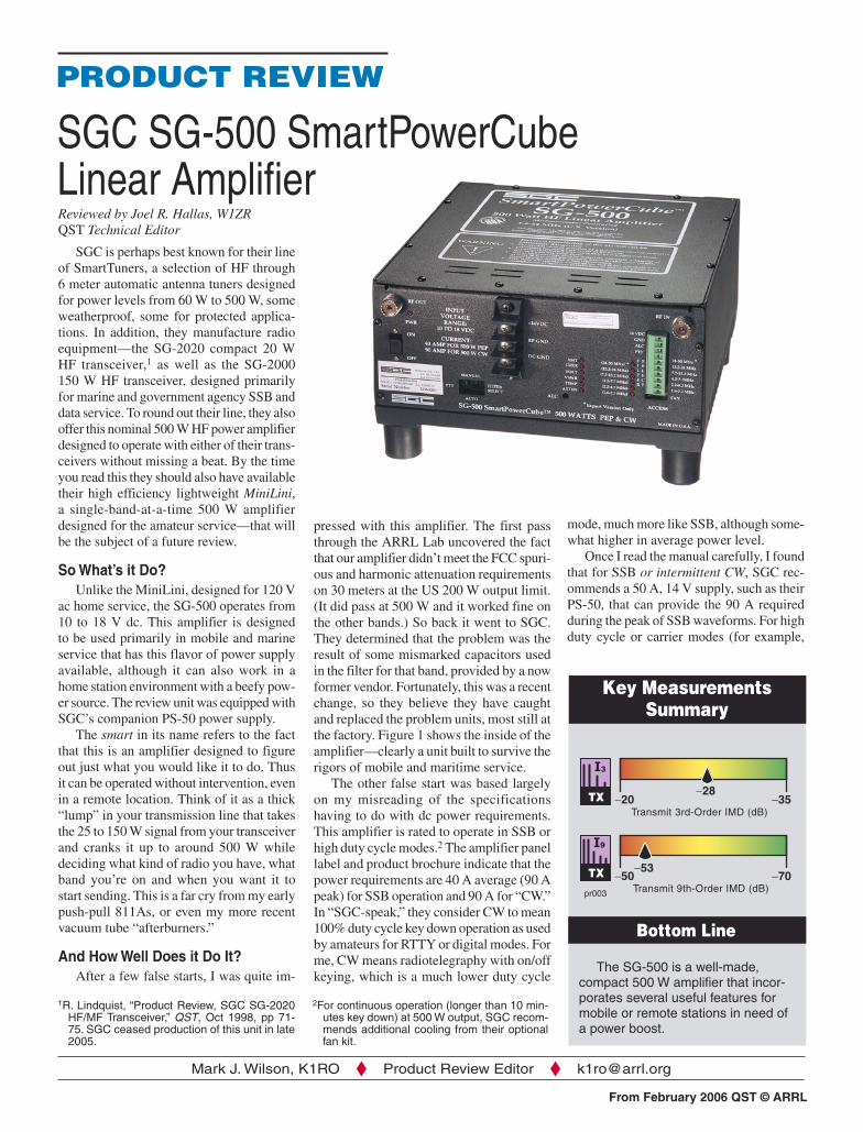
SGC SG-500 SmartPowerCube Linear AmplifierReviewed by Joel R. Hallas, W1ZRQST Technical Editor
SGC is perhaps best known for their line of SmartTuners, a selection of HF through 6 meter automatic antenna tuners designed for power levels from 60 W to 500 W, some weatherproof, some for protected applica-tions. In addition, they manufacture radio equipment—the SG-2020 compact 20 W HF transceiver,1 as well as the SG-2000 150 W HF transceiver, designed primarily for marine and government agency SSB and data service. To round out their line, they also offer this nominal 500 W HF power amplifier designed to operate with either of their trans-ceivers without missing a beat. By the time you read this they should also have available their high efficiency lightweight MiniLini, a single-band-at-a-time 500 W amplifier designed for the amateur service—that will be the subject of a future review.
So What’s it Do?Unlike the MiniLini, designed for 120 V
ac home service, the SG-500 operates from 10 to 18 V dc. This amplifier is designed to be used primarily in mobile and marine service that has this flavor of power supply available, although it can also work in a home station environment with a beefy pow-er source. The review unit was equipped with SGC’s companion PS-50 power supply.
The smart in its name refers to the fact that this is an amplifier designed to figure out just what you would like it to do. Thus it can be operated without intervention, even in a remote location. Think of it as a thick “lump” in your transmission line that takes the 25 to 150 W signal from your transceiver and cranks it up to around 500 W while deciding what kind of radio you have, what band you’re on and when you want it to start sending. This is a far cry from my early push-pull 811As, or even my more recent vacuum tube “afterburners.”
And How Well Does it Do It?After a few false starts, I was quite im-
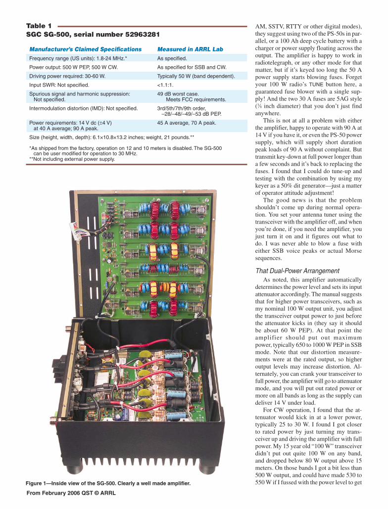
pressed with this amplifier. The first pass through the ARRL Lab uncovered the fact that our amplifier didn’t meet the FCC spuri-ous and harmonic attenuation requirements on 30 meters at the US 200 W output limit. (It did pass at 500 W and it worked fine on the other bands.) So back it went to SGC. They determined that the problem was the result of some mismarked capacitors used in the filter for that band, provided by a now former vendor. Fortunately, this was a recent change, so they believe they have caught and replaced the problem units, most still at the factory. Figure 1 shows the inside of the amplifier—clearly a unit built to survive the rigors of mobile and maritime service.
The other false start was based largely on my misreading of the specifications having to do with dc power requirements. This amplifier is rated to operate in SSB or high duty cycle modes.2 The amplifier panel label and product brochure indicate that the power requirements are 40 A average (90 A peak) for SSB operation and 90 A for “CW.” In “SGC-speak,” they consider CW to mean 100% duty cycle key down operation as used by amateurs for RTTY or digital modes. For me, CW means radiotelegraphy with on/off keying, which is a much lower duty cycle
The SG-500 is a well-made, compact 500 W amplifier that incor-porates several useful features for mobile or remote stations in need of a power boost.
1R. Lindquist, “Product Review, SGC SG-2020 HF/MF Transceiver,” QST, Oct 1998, pp 71-75. SGC ceased production of this unit in late 2005.
2For continuous operation (longer than 10 min-utes key down) at 500 W output, SGC recom-mends additional cooling from their optional fan kit.
I9
I3
mode, much more like SSB, although some-what higher in average power level.
Once I read the manual carefully, I found that for SSB or intermittent CW, SGC rec-ommends a 50 A, 14 V supply, such as their PS-50, that can provide the 90 A required during the peak of SSB waveforms. For high duty cycle or carrier modes (for example,
From February 2006 QST © ARRL
Table 1SGC SG-500, serial number 52963281
AM, SSTV, RTTY or other digital modes), they suggest using two of the PS-50s in par-allel, or a 100 Ah deep cycle battery with a charger or power supply floating across the output. The amplifier is happy to work in radiotelegraph, or any other mode for that matter, but if it’s keyed too long the 50 A power supply starts blowing fuses. Forget your 100 W radio’s TUNE button here, a guaranteed fuse blower with a single sup-ply! And the two 30 A fuses are 5AG style (3⁄8 inch diameter) that you don’t just find anywhere.
This is not at all a problem with either the amplifier, happy to operate with 90 A at 14 V if you have it, or even the PS-50 power supply, which will supply short duration peak loads of 90 A without complaint. But transmit key-down at full power longer than a few seconds and it’s back to replacing the fuses. I found that I could do tune-up and testing with the combination by using my keyer as a 50% dit generator—just a matter of operator attitude adjustment!
The good news is that the problem shouldn’t come up during normal opera-tion. You set your antenna tuner using the transceiver with the amplifier off, and when you’re done, if you need the amplifier, you just turn it on and it figures out what to do. I was never able to blow a fuse with either SSB voice peaks or actual Morse sequences.
That Dual-Power ArrangementAs noted, this amplifier automatically
determines the power level and sets its input attenuator accordingly. The manual suggests that for higher power transceivers, such as my nominal 100 W output unit, you adjust the transceiver output power to just before the attenuator kicks in (they say it should be about 60 W PEP). At that point the amplifier should put out maximum power, typically 650 to 1000 W PEP in SSB mode. Note that our distortion measure-ments were at the rated output, so higher output levels may increase distortion. Al-ternately, you can crank your transceiver to full power, the amplifier will go to attenuator mode, and you will put out rated power or more on all bands as long as the supply can deliver 14 V under load.
For CW operation, I found that the at-tenuator would kick in at a lower power, typically 25 to 30 W. I found I got closer to rated power by just turning my trans-ceiver up and driving the amplifier with full power. My 15 year old “100 W” transceiver didn’t put out quite 100 W on any band, and dropped below 80 W output above 15 meters. On those bands I got a bit less than 500 W output, and could have made 530 to 550 W if I fussed with the power level to get
Manufacturer’s Claimed Specifications Measured in ARRL LabFrequency range (US units): 1.8-24 MHz.* As specified.
Power output: 500 W PEP, 500 W CW. As specified for SSB and CW.
Driving power required: 30-60 W. Typically 50 W (band dependent).
Input SWR: Not specified. <1.1:1.
Spurious signal and harmonic suppression: 49 dB worst case. Not specified. Meets FCC requirements.
Intermodulation distortion (IMD): Not specified. 3rd/5th/7th/9th order, –28/–48/–49/–53 dB PEP.
Power requirements: 14 V dc (±4 V) 45 A average, 70 A peak. at 40 A average; 90 A peak.
Size (height, width, depth): 6.1×10.8×13.2 inches; weight, 21 pounds.**
*As shipped from the factory, operation on 12 and 10 meters is disabled. The SG-500 can be user modified for operation to 30 MHz. **Not including external power supply.
Figure 1—Inside view of the SG-500. Clearly a well made amplifier.
From February 2006 QST © ARRL
below the point that the attenuator kicked in. It was just too fussy with my radio. I decided that if I had a QRP radio, the 11 to 13 dB gain the amplifier provided with the attenuator out would have been great, but for a medium power radio it was easier just to let the attenuator switch in and make use of the resultant 8 to 9 dB gain. A real “100 W” radio would have resulted in about 600 W output on all bands, something I verified with my even older 120 W Drake T4X-C transmitter.
Automatic Transmit Receive SwitchingThe SG-500 includes manual or automa-
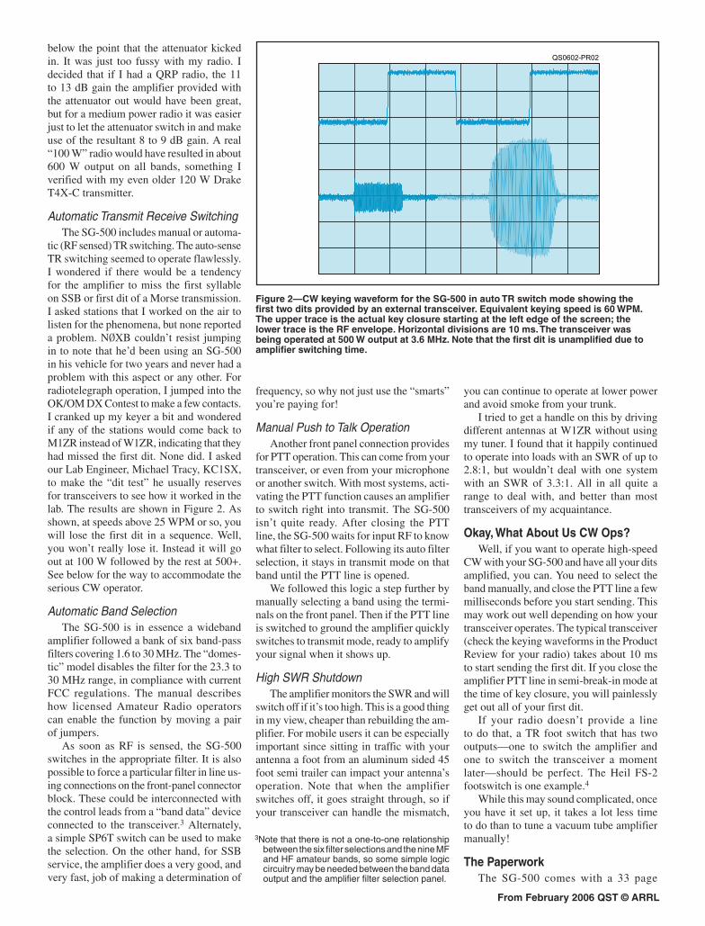
tic (RF sensed) TR switching. The auto-sense TR switching seemed to operate flawlessly. I wondered if there would be a tendency for the amplifier to miss the first syllable on SSB or first dit of a Morse transmission. I asked stations that I worked on the air to listen for the phenomena, but none reported a problem. NØXB couldn’t resist jumping in to note that he’d been using an SG-500 in his vehicle for two years and never had a problem with this aspect or any other. For radiotelegraph operation, I jumped into the OK/OM DX Contest to make a few contacts. I cranked up my keyer a bit and wondered if any of the stations would come back to M1ZR instead of W1ZR, indicating that they had missed the first dit. None did. I asked our Lab Engineer, Michael Tracy, KC1SX, to make the “dit test” he usually reserves for transceivers to see how it worked in the lab. The results are shown in Figure 2. As shown, at speeds above 25 WPM or so, you will lose the first dit in a sequence. Well, you won’t really lose it. Instead it will go out at 100 W followed by the rest at 500+. See below for the way to accommodate the serious CW operator.
Automatic Band SelectionThe SG-500 is in essence a wideband
amplifier followed a bank of six band-pass filters covering 1.6 to 30 MHz. The “domes-tic” model disables the filter for the 23.3 to 30 MHz range, in compliance with current FCC regulations. The manual describes how licensed Amateur Radio operators can enable the function by moving a pair of jumpers.
As soon as RF is sensed, the SG-500 switches in the appropriate filter. It is also possible to force a particular filter in line us-ing connections on the front-panel connector block. These could be interconnected with the control leads from a “band data” device connected to the transceiver.3 Alternately, a simple SP6T switch can be used to make the selection. On the other hand, for SSB service, the amplifier does a very good, and very fast, job of making a determination of
frequency, so why not just use the “smarts” you’re paying for!
Manual Push to Talk OperationAnother front panel connection provides
for PTT operation. This can come from your transceiver, or even from your microphone or another switch. With most systems, acti-vating the PTT function causes an amplifier to switch right into transmit. The SG-500 isn’t quite ready. After closing the PTT line, the SG-500 waits for input RF to know what filter to select. Following its auto filter selection, it stays in transmit mode on that band until the PTT line is opened.
We followed this logic a step further by manually selecting a band using the termi-nals on the front panel. Then if the PTT line is switched to ground the amplifier quickly switches to transmit mode, ready to amplify your signal when it shows up.
High SWR ShutdownThe amplifier monitors the SWR and will
switch off if it’s too high. This is a good thing in my view, cheaper than rebuilding the am-plifier. For mobile users it can be especially important since sitting in traffic with your antenna a foot from an aluminum sided 45 foot semi trailer can impact your antenna’s operation. Note that when the amplifier switches off, it goes straight through, so if your transceiver can handle the mismatch,
you can continue to operate at lower power and avoid smoke from your trunk.
I tried to get a handle on this by driving different antennas at W1ZR without using my tuner. I found that it happily continued to operate into loads with an SWR of up to 2.8:1, but wouldn’t deal with one system with an SWR of 3.3:1. All in all quite a range to deal with, and better than most transceivers of my acquaintance.
Okay, What About Us CW Ops?Well, if you want to operate high-speed
CW with your SG-500 and have all your dits amplified, you can. You need to select the band manually, and close the PTT line a few milliseconds before you start sending. This may work out well depending on how your transceiver operates. The typical transceiver (check the keying waveforms in the Product Review for your radio) takes about 10 ms to start sending the first dit. If you close the amplifier PTT line in semi-break-in mode at the time of key closure, you will painlessly get out all of your first dit.
If your radio doesn’t provide a line to do that, a TR foot switch that has two outputs—one to switch the amplifier and one to switch the transceiver a moment later—should be perfect. The Heil FS-2 footswitch is one example.4
While this may sound complicated, once you have it set up, it takes a lot less time to do than to tune a vacuum tube amplifier manually!
The PaperworkThe SG-500 comes with a 33 page
Figure 2—CW keying waveform for the SG-500 in auto TR switch mode showing the first two dits provided by an external transceiver. Equivalent keying speed is 60 WPM. The upper trace is the actual key closure starting at the left edge of the screen; the lower trace is the RF envelope. Horizontal divisions are 10 ms. The transceiver was being operated at 500 W output at 3.6 MHz. Note that the first dit is unamplified due to amplifier switching time.
3Note that there is not a one-to-one relationship between the six filter selections and the nine MF and HF amateur bands, so some simple logic circuitry may be needed between the band data output and the amplifier filter selection panel.
QS0602-PR02
From February 2006 QST © ARRL
manual, cleverly subtitled “Power Tools.” Included are the usual sections on safety, proper antenna characteristics, power sup-ply options, operation and troubleshooting, including a set of test procedures to verify proper operation. Six pages are dedicated to a block diagram and schematics of each section of the amplifier.
This manual clearly answered all my questions on how to connect up and use the SG-500—there’s not much more that I could ask for. This is especially the case for an amplifier that’s designed to configure itself every time it’s driven, once you hook it up.
Good Job SGC!After all is said and done, this amplifier
delivers as advertised. Table 1 indicates that it meets its specifications very handily and is better at intermodulation distortion products than I would have expected from a 12 to 14 V amplifier. The folks who promote FET amplifiers contend that they are much cleaner, but you couldn’t tell that from our testing of the SG-500.
If you want an amplifier that will deliver
the goods and not require lots of attention, this should be a serious contender. The lack of user controls is a real convenience and does not seem to be an impediment to SSB operation—I believe it was designed with SSB in mind. For those of us who still use Morse, you won’t get full break-in, but then again they didn’t promise that. Otherwise, given the functionality described above, it can work very well on Morse in semi-break-in mode.
A Bit About Power SourcesYou do need to plan your power system
carefully with this, or any device that can draw 90 A during signal peaks. This was quite evident to us after a minor rearrange-ment slightly detorqued the connection of one of the power leads. A lesser device might not have noticed, but when the full amplifier current kicked in, the voltage drop caused by the increase in connection resistance resulted in the relays dropping out. It was rather dramatic, relays going in and out with each syllable. A quick applica-tion of a screwdriver solved my problem. If the amplifier were mounted remotely and had significant vibration, you might not know about a loose power connection until
some other evidence gave you a clue. The answer—keep those connections securely tightened!
SGC recommends using 6 gauge wire for power connections to the SG-500. This is larger than many hams are used to, and putting terminals for this size wire on the barrier strip provided can be a challenge. For our testing, we elected to use parallel 10 gauge wires, but they were just long enough to reach between the power supply and am-plifier. Just to give an idea, if you used a pair of 10 foot, 10 gauge wires (about as thick as recommended for most 100 W mobile instal-lations) to connect to this amplifier, at 90 A the drop would be 1.8 V. This could be the difference between working and not work-ing, if your battery supply had discharged below 12 V, and it doesn’t take long with this kind of load! SGC recommends reading Go Mobile at 500 W, available for download from the SGC Web site, for detailed infor-mation about using the amplifier in a mobile environment.
Manufacturer: SGC Inc, 13737 SE 26th St, Bellevue, WA 98005; tel 425-746-6310; fax 425-746-6384; www.sgcworld.com. Price: SG-500, $1395; PS-50, $459.50; Cooling fan kit, $300.4See www.heilsound.com.
Reviewed by Dan Henderson, N1NDARRL Contest Manager
I had been asked to review a pair of new Yaesu 2 meter handhelds, but I had to do a double take when I first looked at the VX-120 and VX-170 sitting on my desk. My first reaction after looking at the two was that I was staring at an older brother/younger brother duo. You know, the VX-170 was full and mature and the VX-120 was just starting to come into its own but not quite grown up.
My initial impression turned out to be wrong. Both proved to be reliable, rugged handhelds capable of performing at the accustomed high standard. They offer 5 W output, wideband receive, great receiver audio and long battery life in a compact, weatherproof package. While there is a notable difference, both will serve their owners well with many desired functions. Unless otherwise noted, comments in this review apply to both the VX-120 and the
Yaesu VX-120 and VX-170 2 Meter Handheld Transceivers VX-170. Any differences between the two
radios will be clearly stated.
Two Very Similar RadiosFor the most part, both radios perform
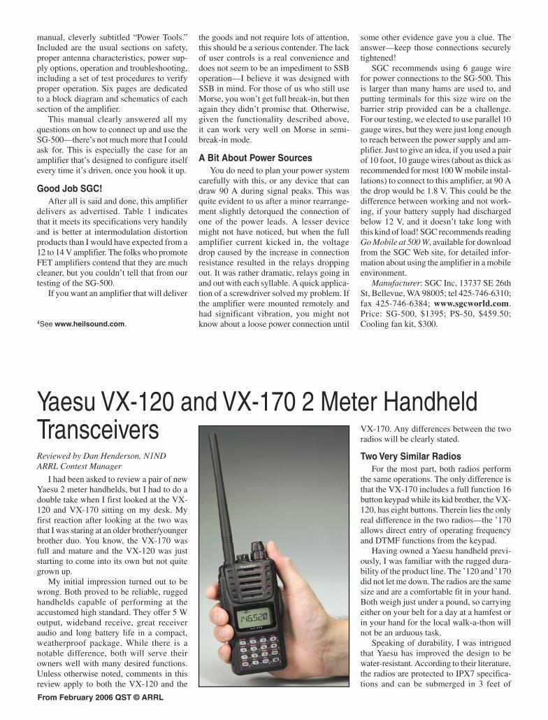
the same operations. The only difference is that the VX-170 includes a full function 16 button keypad while its kid brother, the VX-120, has eight buttons. Therein lies the only real difference in the two radios—the ’170 allows direct entry of operating frequency and DTMF functions from the keypad.
Having owned a Yaesu handheld previ-ously, I was familiar with the rugged dura-bility of the product line. The ’120 and ’170 did not let me down. The radios are the same size and are a comfortable fit in your hand. Both weigh just under a pound, so carrying either on your belt for a day at a hamfest or in your hand for the local walk-a-thon will not be an arduous task.
Speaking of durability, I was intrigued that Yaesu has improved the design to be water-resistant. According to their literature, the radios are protected to IPX7 specifica-tions and can be submerged in 3 feet of
From February 2006 QST © ARRL
Table 2Yaesu VX-170, serial number 5G020586
Manufacturer’s Specifications Measured in ARRL LabFrequency coverage: Receive, 137-174 MHz; Receive and transmit, as specified. transmit, 144-148 MHz.
Power requirements: 6-16 V dc; receive, Receive (max volume, no signal), 0.12 A; transmit, 1.5 A (max, high power). 0.32 A (battery), 0.53 A (13.8 V); transmit, 1.3 A (battery), 1.5 A (13.8 V).*
Receiver Receiver Dynamic TestingSensitivity, 12 dB SINAD: 137-140, 150- For 12 dB SINAD: 146 MHz, 0.16 µV. 174 MHz, 0.2 µV; 140-150 MHz, 0.16 µV.
Two-tone, third-order IMD dynamic range: 20 kHz offset: 146 MHz, 68 dB; ** Not specified. 10 MHz offset: 146 MHz, 84 dB.
Two-tone, second-order IMD dynamic range: 146 MHz, 73 dB. Not specified.
Adjacent-channel rejection: Not specified. 20 kHz offset: 146 MHz, 68 dB.
Spurious response: Not specified. IF rejection, 146 MHz, 105 dB; image rejection, 146 MHz, 103 dB.
Squelch sensitivity: Not specified. At threshold, 0.14 µV.
Audio output: 700 mW at the speaker; ext jack Ext jack, 390 mW at 10% THD into 8 Ω. 400 mW at 10% THD into 8 Ω.
Transmitter Transmitter Dynamic Testing*Power output: 5.0 W high, 2.0 W mid, 5 / 2 / 0.5 W (battery); 0.5 W low. 5 / 2 / 0.5 W (13.8 V).
Spurious signal and harmonic suppression: 72 dB. Meets FCC requirements. 60 dB.
Transmit-receive turnaround time (PTT release Squelch on, S9 signal: 200 ms. to 50% of full audio output): Not specified.
Receive-transmit turnaround time (“tx delay”): 100 ms. Not specified.
Size (height, width, depth): 4.7×2.4×1.3 inches; weight, 13.8 ounces.*The transceiver was tested with the supplied FNB-83 battery pack (7.2 V, 1.4 Ah) and with an external 13.8 V dc supply.**Measurement was noise limited at the value indicated.
Key Measurements Summary
Bottom Line
water for up to 30 minutes.5 I resisted the temptation to test this out in the bathtub upstairs so I can’t vouch for the claim, but other Yaesu radios we have reviewed have passed the test with flying colors. If you take your handheld to the lake or hiking, being water-resistant would be a welcome feature when you slip on the rock while crossing the stream or tip the canoe while paddling to the other side. It also provides some additional reliability for emergency communications work in foul weather.
As always, the basic first test for me is “how easily and quickly can I use my new
toy?” The ’120 and ’170 didn’t let me down. The batteries had already been charged for ARRL Lab testing, so about three minutes with the manual and another two minutes to snap on the battery pack and screw in the antenna and voila! A twist of the VOL/PWR knob on top and the radios were powered up and ready for action.
My immediate impression after power-up was that the display screen on the front of the radios is large and easy to read—making it easy on these older eyes that need reading glasses. The display is easy to read in sun-light as well—again, a good thing for tired eyes. The LCD and keypad are illuminated with a bright orange for easy use at night or in dark places. It’s an improvement com-pared to the older Yaesu VX-150.
The inner portion (or top) of the knob on top of the radio is the ON/OFF and VOLUME control. The outer portion (or bottom) of the knob constitutes the DIAL and is used for setting the operating frequency, menu selec-tions and other adjustments on the radio. The DIAL and MHZ UP/DOWN keys are used for
5IEC 529 is a European standard for testing the degree of protection provided by electrical equipment enclosures against damage from water and solid objects. Under IEC 529, an IPX7 designation means that the radio can withstand temporary immersion in up to 1 meter of water for 30 minutes. You may have seen this rating applied to GPS devices, marine radar and other electronics equipment intended for outdoor use. The Yaesu VX-6R reviewed in December 2005 was rated for JIS7, which is a similar Japanese industry standard for submersion.
Whether you are looking for a very basic first 2 meter FM radio or for a new tool to add to your collection of gear, the VX-120 and VX-170 provide quality, reliable 2 meter portable com-munications at a good value.
I3
I3
frequency navigation on the VX-120, while the VX-170 adds the convenience of enter-ing an operating frequency directly from its expanded keypad (for example, 46520 for 146.52 MHz).
After turning the radio on, I tuned to a local repeater and put out a call. The repeater sent its ID, and I was amazed at
Note: Internal speaker audio output power specified (not tested) at 700 mW.
From February 2006 QST © ARRL
the great sounding audio coming from the radio—even with the volume turned up. This is a major improvement over most other handhelds I have used in 35 years of Amateur Radio.
Easy Access to MenusAfter a couple of quick QSOs, it was
time to spend some “quality time” with the manual, looking at the wide range of operational abilities for each radio. One of the most common complaints over the years is that many manuals are too complicated or difficult to use. I believe Yaesu has heard these comments as well, because I found that, on the whole, the manuals were very user friendly.
Because so many features are incorpo-rated into today’s transceivers, program-ming and accessing them can sometimes be confusing and daunting. The ’120 and ’170 use what the manual refers to as a SET (MENU) MODE to access and adjust these features. Each radio has a total of 57 dif-ferent user-settable features, ranging from basic tasks (such as automatic power off, shift offset or scanning features) to more advanced, such as setting the Internet Link Connection mode. Five of the menu features appear only when an optional DTMF paging unit is installed.
Many of the SET MODE features are described in detail in the main text of the manual, but incorporated in the back of the manual are three different summary descriptions of all SET MODE items. One is arranged by topic, another by menu number with detailed descriptions and information, and a third is condensed into an easy-to-use two-page chart. If you use a “cheat sheet” for your power amplifier or antenna tuner set-tings on your HF rig, this index will perform the same function for your handheld.
So What Can These Radios Do?These radios include several particularly
appealing features. For example, most newer handheld radios have a power-saver function on their receivers. The VX-120 and VX-170 incorporate a power save function on the transmitter side as well. Simply put, when the transceiver senses that the last received signal was very strong, it will automatically change from high power to low power if it senses that high power is not necessary to achieve full quieting into the repeater. This feature has the potential to extend the life of a battery charge if conditions are right.
Speaking of drain on the battery, the standard battery pack provides 1400 mAh—about double what the VX-150 pack supplied. This will extend your operating capability while using the radio in those daylong public service events or even just
ragchewing with your friends during the daily commute.
It takes about 10 hours to charge the bat-tery using the supplied NC-88 wall charger or an external 12 to 16 V dc supply. If you need a shorter charging time, check out the VAC-370 desktop drop-in charger, which shortens charging time to about 1.5 hours.
Microprocessors and memory chips have allowed greater capability for memory stor-age. Both radios come with a full 200 memo-ries of storage capability, plus a “home” channel that can be quickly accessed from a push-button. The memories include 10 sets of band edge memories and 10 NOAA weather channels. Memories can be labeled with frequency or with alphanumeric tags.
You might find 200 memories a bit over-whelming, so Yaesu allows you to arrange the 200 memories into 10 banks. You might use one bank for the local repeaters and club frequencies, another for emergency com-munication frequencies, and another for a trip you’re planning to take. Each bank can include any or all of the 200 memories, and memories can be assigned to more than one bank. For example, you might include the 146.52 MHz simplex frequency in all banks. The memories store CTCSS tones as well as frequency. So if you take the radio while you travel, you can program the home repeater with its CTCSS tone in one memory and set up another memory for a repeater that uses the exact same frequency pair but a different CTCSS tone.
A useful feature for those involved with emergency communications or search-and-rescue operations is the automatic range transponder system—ARTS for short. When the radio is operating with ARTS activated and is within range of another ARTS-activated radio using the same digital code squelch (DCS) codes, the transceiver display and an audible signal alert you that the two radios are within range. When ARTS is activated, the VX-120 and VX-170 will transmit a brief digital code (about 1 second) every 15 or 25 seconds. This type system has become more popular among fire and rescue services, and is an excellent tool when amateurs are working in cooperation with emergency personnel.
If you don’t have a weather radio that automatically activates when the National Weather Service issues a severe weather alert in your area, these radios have dedicated weather memory channels and can be pro-grammed to notify you in an emergency. This feature has become almost standard on all new VHF transceivers. I believe every home should have a radio with this important safety feature, and it’s on my list of “must haves” when deciding to purchase a transceiver.
Like to keep your radio on in case some-
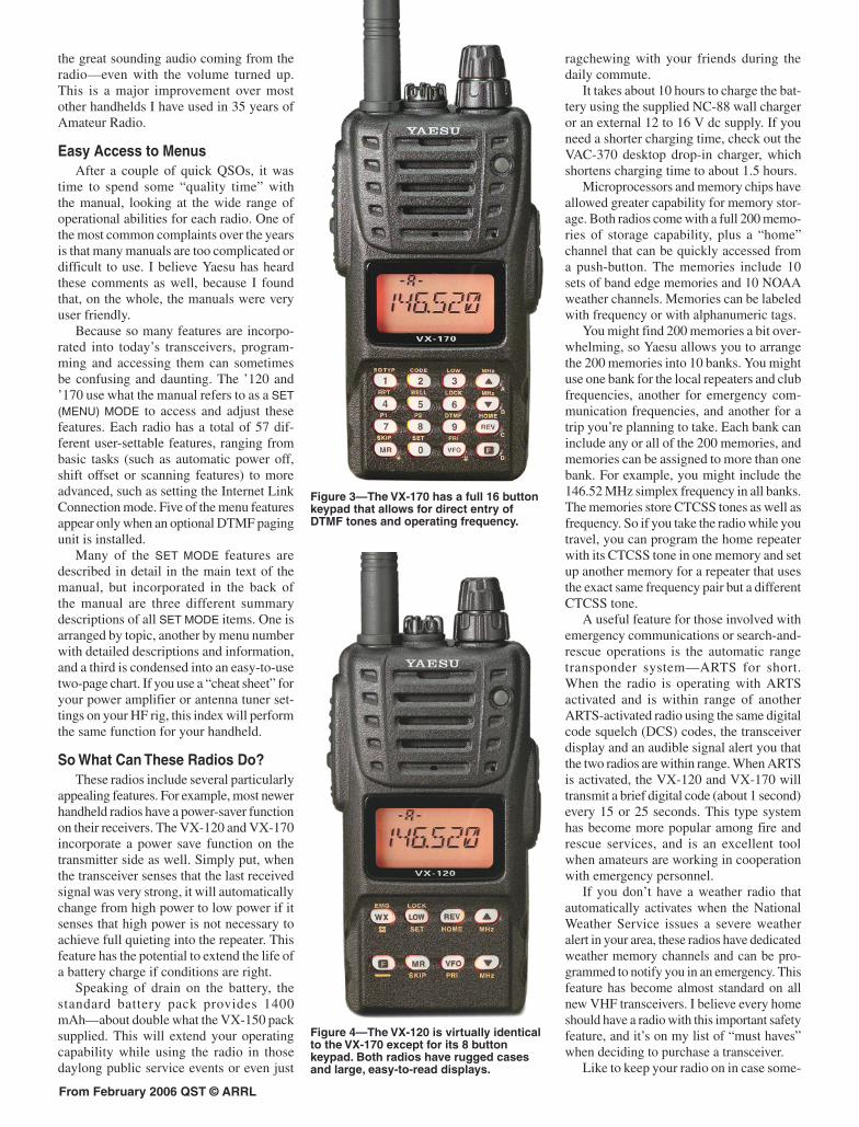
Figure 3—The VX-170 has a full 16 button keypad that allows for direct entry of DTMF tones and operating frequency.
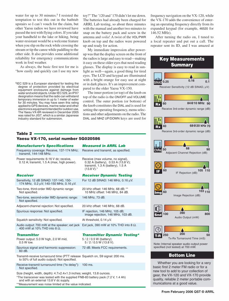
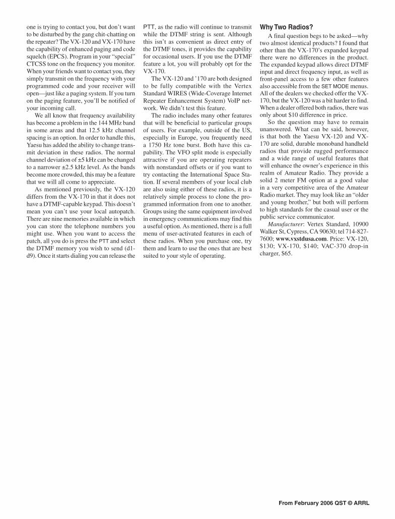
Figure 4—The VX-120 is virtually identical to the VX-170 except for its 8 button keypad. Both radios have rugged cases and large, easy-to-read displays.
From February 2006 QST © ARRL
one is trying to contact you, but don’t want to be disturbed by the gang chit-chatting on the repeater? The VX-120 and VX-170 have the capability of enhanced paging and code squelch (EPCS). Program in your “special” CTCSS tone on the frequency you monitor. When your friends want to contact you, they simply transmit on the frequency with your programmed code and your receiver will open—just like a paging system. If you turn on the paging feature, you’ll be notified of your incoming call.
We all know that frequency availability has become a problem in the 144 MHz band in some areas and that 12.5 kHz channel spacing is an option. In order to handle this, Yaesu has added the ability to change trans-mit deviation in these radios. The normal channel deviation of ±5 kHz can be changed to a narrower ±2.5 kHz level. As the bands become more crowded, this may be a feature that we will all come to appreciate.
As mentioned previously, the VX-120 differs from the VX-170 in that it does not have a DTMF-capable keypad. This doesn’t mean you can’t use your local autopatch. There are nine memories available in which you can store the telephone numbers you might use. When you want to access the patch, all you do is press the PTT and select the DTMF memory you wish to send (d1-d9). Once it starts dialing you can release the
PTT, as the radio will continue to transmit while the DTMF string is sent. Although this isn’t as convenient as direct entry of the DTMF tones, it provides the capability for occasional users. If you use the DTMF feature a lot, you will probably opt for the VX-170.
The VX-120 and ’170 are both designed to be fully compatible with the Vertex Standard WIRES (Wide-Coverage Internet Repeater Enhancement System) VoIP net-work. We didn’t test this feature.
The radio includes many other features that will be beneficial to particular groups of users. For example, outside of the US, especially in Europe, you frequently need a 1750 Hz tone burst. Both have this ca-pability. The VFO split mode is especially attractive if you are operating repeaters with nonstandard offsets or if you want to try contacting the International Space Sta-tion. If several members of your local club are also using either of these radios, it is a relatively simple process to clone the pro-grammed information from one to another. Groups using the same equipment involved in emergency communications may find this a useful option. As mentioned, there is a full menu of user-activated features in each of these radios. When you purchase one, try them and learn to use the ones that are best suited to your style of operating.
Why Two Radios?A final question begs to be asked—why
two almost identical products? I found that other than the VX-170’s expanded keypad there were no differences in the product. The expanded keypad allows direct DTMF input and direct frequency input, as well as front-panel access to a few other features also accessible from the SET MODE menus. All of the dealers we checked offer the VX-170, but the VX-120 was a bit harder to find. When a dealer offered both radios, there was only about $10 difference in price.
So the question may have to remain unanswered. What can be said, however, is that both the Yaesu VX-120 and VX-170 are solid, durable monoband handheld radios that provide rugged performance and a wide range of useful features that will enhance the owner’s experience in this realm of Amateur Radio. They provide a solid 2 meter FM option at a good value in a very competitive area of the Amateur Radio market. They may look like an “older and young brother,” but both will perform to high standards for the casual user or the public service communicator.
Manufacturer: Vertex Standard, 10900 Walker St, Cypress, CA 90630; tel 714-827-7600; www.vxstdusa.com. Price: VX-120, $130; VX-170, $140; VAC-370 drop-in charger, $65.
From February 2006 QST © ARRL
the CHA-250B. I received reports of my signal being down as much as 3 S units when I switched to the Comet.
On 80, 40 and 30 me-ters, I switched between the CHA-250B and an inverted V antenna. I didn’t expect stellar performance from the ’250B on these bands, so I wasn’t disappointed. The CHA-250B, at best, equaled the performance of a mobile whip an-tenna.
Claims vs RealityIf Comet had claimed
that the CHA-250B was a world-beating miracle antenna, we would have blasted it with both bar-rels. Comet doesn’t make such claims, however. Their literature merely states that the antenna will radiate a signal and provide a low SWR on all bands without the use of radials. In this respect,
the CHA-250B performs as advertised. It is neither a miracle nor a fraud.
The CHA-250B’s performance is mediocre to poor on 80, 40 and 30 meters, but it does an adequate job on the other bands. At a list price of $469, this is hardly an inexpensive antenna. Frankly, a small antenna tuner, a length of 450-Ω ladder line and a wire dipole will yield superior performance at less than half the price.
But not everyone has room for a dipole antenna. Some people are confined to very small spaces that will hardly accommodate a wire antenna of any kind, and certainly not a vertical antenna with a network of radial wires. In circumstances where choices are extremely limited and cost isn’t a major consideration, the Comet CHA-250B may be a contender, especially if the alternative is not getting on the air at all. In addition, the CHA-250B may also be a viable option in emergencies when you need a multiband HF antenna that can be deployed in a matter of minutes. In those situ-ations you just want to get a signal on the air, not work the world.
Distributed in the US by NCG Com-panies Inc, 1275 North Grove St, Anaheim, CA 92806; www.cometantenna.com . $469.
Steve Ford, WB8IMY QST Editor [email protected]
What if I said that you could buy a vertical antenna that works on 80 through 6 meters without radial wires and offers an SWR of less than 1.6:1 throughout each band? Would you believe me?
If this description triggers alarm bells in your head, good for you. It shows that you’ve been paying attention to antenna articles in QST and elsewhere. Maybe you even own a copy of the ARRL Antenna Book. Heed those alarm bells well. They’re telling you that there is no such thing as a miracle antenna or a free lunch (well, maybe a free lunch).
Most vertical antennas require ground returns for RF currents, either through elevated radial wires or radial wires in (or on) the soil. An efficient vertical antenna will not offer an SWR of 1.6:1 across each band. In fact, the 2:1 SWR bandwidth of a highly ef-ficient vertical can be quite narrow.
So what is going on with the Comet CHA-250B? This new vertical antenna promises an SWR less than 1.6:1 from 3.5 to 54 MHz without using radials. Is it a miracle or a fraud?
Assembly and SetupThe Comet CHA-250B is easy to assemble. There is little more
to do than fit one aluminum tube into another. The CHA-250B we purchased for this review came with assembly instructions in Japanese (current models have English instructions). I don’t read Japanese, but I was still able to put the antenna together by simply following the diagram. When you’re finished (15 minutes later, in my case), you have a 231⁄2-foot long antenna that’s ready for use.
Comet recommends that the CHA-250B be mounted at a height of 35 feet for best performance, but I opted to test the antenna in a more typical near-ground installation using a short tripod in my backyard. The antenna only weighs about 7 pounds, but its length makes it unwieldy for one person to handle alone. I’d strongly recommend a helper because the ’250B has a tendency to sway at the top. It is difficult to hold the base still while the top is oscillating!
On-Air PerformanceTrue to its specifications, our CHA-250B
really did deliver a low SWR on every band. Regardless of the frequency, I never measured an SWR higher than 1.3:1. The CHA-250B achieves this through a sealed “matching unit” in an aluminum cylinder at the base of the antenna. According to Comet, the matching circuit is basically a network of resistors and capacitors. A toroid balun is present as well.
But the concept of a “radialess” low-SWR vertical antenna meets hard reality when you actually get on the air. Using an A/B coax switch, I toggled between the CHA-250B and a Fluidmotion SteppIR vertical antenna with a conventional radial system. On 20 through 6 meters, the CHA-250B and the SteppIR were comparable when it came to reception. On transmission, the SteppIR clearly outperformed
Comet CHA-250B Vertical Antenna
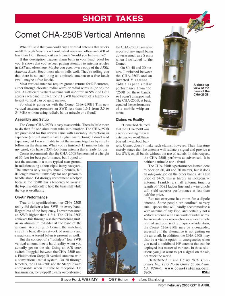
A close-up view of the base of the CHA-250B.
SHORT TAKES