Embed Size (px)
Citation preview

Product Range
2020

WELCOME TOBRITISH STEELBritish Steel is one of Europe’s leading steel manufacturers, producing around 3
million tonnes of quality steel products every year. We supply high-quality rail,
sections, special profiles, wire rod and a variety of semi-finished products for
some of the most demanding applications around the world.
In March 2020, we were bought by distinguished Chinese multi-industrial company
Jingye Group, beginning a new chapter in British steelmaking.
Our steelworks have existed for around 150 years and we’re excited about what we
can collectively achieve to build a successful future for many years to come.
PRODUCT RANGE & SPECIFICATIONS2

SCUNTHORPE
SKINNINGROVELISBURN
DUBLIN
WORKINGTON
NEWPORT
ALBLASSERDAM
SHEFFIELD
TEESSIDE
DARLINGTON
MANUFACTURING
SERVICE CENTRE
R&D FACILITIES
DISTRIBUTION FACILITIES
STEELMAKING
Location Semi-finished products
Sections Special profiles
Wire rod Rail Services
Scunthorpe
Teesside Processing, cutting, shotblasting and painting
Skinningrove
Darlington Cutting, shotblasting, drilling and notching
Workington Engineering
Lisburn Processing, cutting, shotblasting and painting
Alblasserdam Wire drawing, annealing and pickling
Our operationsWe have a range of operations across the UK and Europe,
supported by an international chain of sales offices.
Our steel is produced in Scunthorpe via the basic oxygen
steelmaking (BOS) route. Our mills take this carefully made
steel and roll it into a range of products that we supply across
the world.
3PRODUCT RANGE & SPECIFICATIONS

Automotive Construction Energy & Power
Construction & Earthmoving Equipment Defence & Security Rail Infrastructure
Consumer Goods
Photo courtesy of Andrew Linnett/MOD
THE MARKETS WE SERVEOur wide range of products, manufactured to
internationally recognised standards, are used in many
markets and demanding applications, helping share the
modern world we see around us every day.
Our steel has helped build some of the world’s most iconic
and awe-inspiring projects, including:
• The Shard, London
• Crossrail, London
• Petronas Towers, Kuala Lumpur
• Camlica Tower, Istanbul
• Yankees Stadium, New York
• Harmony of the Seas cruise ship
PRODUCT RANGE & SPECIFICATIONS4

CONTENTS1 SPECIAL PROFILES 6
1.1 Bulb flats 8
1.2 Condumax® cathode bars 16
1.3 Crane rail 20
1.4 Cutting edge 24
1.5 Forklift profiles 30
1.6 Mining – tophats 34
1.7 Trackshoe profiles 40
1.8 Melting Base Iron (MBI) 47
2 WIRE ROD 48
2.1 Cold heading 50
2.2 Freecutting 53
2.3 Tyre reinforcement 56
2.4 Automotive spring steel 58
2.5 Rail clip 60
2.6 Bearing steel 62
2.7 Welding steel 65
2.8 High tensile 68
2.9 Wire Processing Centre 70
3 CONSTRUCTION 73
3.1 UK sections 75
• Universal beams 76
• Universal columns 79
• Universal bearing piles 80
• Parallel flange channels 81
• Asymmetric beams 82
• Unequal angles 82
• Equal angles 83
3.2 American sections 84
• American wide flange beams (W) 86
• American wide flange bearing piles (HP) 88
3.3 European sections 92
• European I beams (IPE) 93
• European wide flange beams (HE) 94
3.4 Service centres and distribution facilities 96
4 RAIL
4.1 Rail profiles and grades 100
4.2 HP 103
4.2 Zinoco® 105
4.3 Steel sleepers 107
5 SEMI-FINISHED PRODUCTS 109
5.1 Slabs 111
5.2 Blooms 114
5.3 Billets 117
6 CONTACTS 120
98
5PRODUCT RANGE & SPECIFICATIONS

1 SPECIAL PROFILES

ABOUT SPECIAL PROFILESOur Special Profiles mill is located in Skinningrove in the
north east of England; from here we are able to deliver all
around the world.
We provide unique steel solutions for unique applications;
our extensive range of special profiles is used to make
components for a wide range of industries from shipbuilding
to construction and earthmoving equipment; material
handling to mining.
Whether its building a ship, manufacturing earthmoving
equipment or designing a mine shaft, our technical and roll
design teams are on hand to work with you to create the
optimum profile shape for your application.
We can roll profiles up to 260kg/metre – from simple
profiles with non-standard dimensions, to highly complex
and asymmetrical shapes. We supply both ‘reserved’
profiles designed for individual customer needs and ‘open’
roll profiles which are available to all customers. Through
establishing long-term relationships with our customers we
are able to help them develop and modify the profile ranges
they require.
We also offer additional processing including cold sawing
to exact length, shot blasting, painting and a range
of fabrication and machining operations to meet our
customers’ requirements.
7PRODUCT RANGE & SPECIFICATIONS
1.1 BULB FLATS

1.1 BULB FLATS
Light weight corrosion resistant solution for plate stiffening
Bulb flats are the most cost-effective, efficient and corrosion-
resistant solution for plate stiffening. They provide an excellent
strength to weight ratio delivering buckling resistance at a
lower weight than flat bars or angles.
We supply bulb flats in a wide range of steel types and grades.
We also offer a choice of finishing services to meet our
customers’ needs. These include:
• Shot blasting and priming – to provide improved
fabrication performance and protection
• Weld edge preparation to reduce preparation required for
automated welding
• A range of enhanced dimensional tolerances giving
further weight and engineering enhancements to your
designs
Our flexible and regular rolling programme of all our products
means we can help our customers achieve closer project
schedule adherence.
We are ISO 9001 and ISO 14001 compliant. We also have
approval of the world’s leading classification societies
including: ABS, BV, CCS, DNV, GL, LRS, RINA and MRRS.
Strength Grade
A, B
Normal D
E
A32
D32
High strength A36
D36
E36
Euronorm Grade
ASTM A572 Gr50
S235JR+AR
S235J0+AR
S235J2+AR
S275JR+AR
EN10025-2 S275J0+AR
S275J2+AR
S355JR+AR
S355J0+AR
S355J2+AR
EN10025-4 S355M
EN10225 G11
G12
Grades that are held in bloom stock, readily
available to roll in the next available capacity
The following grades are within our
capability and steel is made to order
Other grades may also be available upon request.
Shipbuilding steels Structural steels
Steel types and grades
9PRODUCT RANGE & SPECIFICATIONS

1.1 BULB FLATS
Dimensions
Dimensional tolerances
Width
Thickness
Length
b
t mm
mm
Width, b (mm) 160-430
Thickness, t (mm) 7-20
Length (m) 6-16.5*
* short cuts and longer lengths up to 18m available on request
Width b, (mm) EN10067Standard Special 1 Special 2
≥ 160 ≤ 180 ±2.0mm ±2.0mm ±1.5 mm
> 180 ≤ 300 ±3.0mm ±2.2mm ±1.7 mm
> 300 ≤ 430 ±4.00mm ±3.0mm ±2.0 mm
Our special width tolerances are achieved through
an offline 100% weld edge grinding process.
This ensures clean flat edges for superior welding.
Thickness t tolerances for different widths ranges.
Width b, (mm) EN10067 Standard Special 1
≥ 160 ≤ 180 -0.3 /+ 1.0mm -0.2 / + 0.6mm
> 180 ≤ 300 -0.4/ + 1.0mm -0.3 / + 0.6mm
> 300 ≤ 430 -0.4/ + 1.2mm -0.3 / + 0.6mm
Closer tolerances may be achieved by special agreement.
Individual lengths between 6m and 16.5m are available as a
standard stackable length. Lengths outside this range (1.5m to
18m) may be available on request on a limited tonnage basis.
Length, L EN10067 Standard
All -0 / + 100 mm
PRODUCT RANGE & SPECIFICATIONS10

1.1 BULB FLATS
Straightness – bow and camber
Twist
As measured over the length of the bar.
q
L (M) Length of profile
Length EN10067 Standard Special 1 Special 2
L ≤ 18m q ≤ 0.0035 x L q ≤ 0.0025 x L q ≤ 0.00125 x L
The permissible degree of twist is given as the following:
b
T
Torsion: T = b x sin 0.35º x L - Special steel 1
Torsion: T = b x sin 0.5º x L - Standard steel
Length, L 6m 10m 12m 15m 18m
Permitted twist 0.35° 0.5° 0.35° 0.5° 0.35° 0.5° 0.35° 0.5° 0.35° 0.5°
Width, b (mm)
160 5.86 8.38 9.77 13.96 11.73 16.75 14.66 20.94 17.59 25.13
180 6.60 9.42 11.00 15.71 13.19 18.85 16.49 23.56 19.79 28.27
200 7.33 10.47 12.22 17.45 14.66 20.94 18.33 26.18 21.99 31.42
220 8.06 11.52 13.44 19.20 16.13 23.04 20.16 28.80 24.19 34.56
240 8.80 12.57 14.66 20.94 17.59 25.13 21.99 31.42 26.39 37.70
260 9.53 13.61 15.88 22.69 19.06 27.23 23.82 34.03 28.59 40.84
280 10.26 14.66 17.10 24.43 20.52 29.32 25.66 36.65 30.79 43.98
300 11.00 15.71 18.33 26.18 21.99 31.42 27.49 39.27 32.99 47.12
320 11.73 16.75 19.55 27.92 23.46 33.51 29.32 41.89 35.19 50.26
340 12.46 17.80 20.77 29.67 24.92 35.60 31.15 44.51 37.38 53.41
370 13.56 19.37 22.60 32.29 27.12 38.75 33.90 48.43 40.68 58.12
400 14.66 20.94 24.43 34.91 29.32 41.89 36.65 52.36 43.98 62.83
430 15.76 22.51 26.27 37.52 31.52 45.03 39.40 56.29 47.28 67.54
Torsion, T (mm)
Length Standard Special 1
All 0.5°/m 0.35°/m
Torsion, T (mm) = width (mm) x sin tol degree, x length (M)
Twist can be difficult to measure and is easiest to measure converted into Torsion by
measuring the Torsion T in mm and applying the following calculations:
11PRODUCT RANGE & SPECIFICATIONS

1.1 BULB FLATS
Flatness
Shape
The plate flatness tolerance h is 0.3% of the bulb flat width b and is measured as shown below.
Plate flatness tolerance: h ≤ 0.003 x b
b
h
The bulb flatness tolerance of the heel is n measured as shown below with a 2mm maximum.
Bulb flatness tolerance: n ≤ 2.0 mm
n
h mm
mm
The dimensions s and f are measured as
illustrated above.
Bulb head corner tolerances s
Bulb head corner tolerances f
The dimension r1 is measured as illustrated above.
Bulb head corner tolerances radius r1
Radius of curvature of corners
r1 for thickness
Thickness Tolerance
t ≤ 9 mm s ≤ 2.0mm
9 < t ≤ 13 mm s ≤ 3.0mm
t > 13 mm s ≤ 4.0mm
Thickness Tolerance
t > 7 mm f ≤ 0.75 S
Thickness r1 ≤
5 < t ≤ 9 2.0mm
9 ≤ t < 13 3.0mm
13 ≤ t ≤ 20 4.0mm
t
f
s r1
mm
mm
mm mm
PRODUCT RANGE & SPECIFICATIONS12

1.1 BULB FLATS
The dimension e is measured as illustrated above.
Web edge tolerances e
Tighter tolerances may be available on request through
grinding of the web edge.
The dimension w is measured as illustrated above.
Web edge tolerances angle w
Tighter tolerance on web edge tolerance e and angle w
may be available on request through offline grinding of
the web edge.
Surface condition
The surface requirements and repair conditions for
shipbuilding profiles are in accordance with EN10163-
3:2004, subclass 3, class C. Maximum permissible depth
of discontinuities and grinding allowance below minimum
specified thickness are given in the table below:
Thickness EN10067 - Standard
t ≤ 9 mm e ≤ 2.0mm
9 < t ≤ 13 mm e ≤ 3.0mm
t > 13 mm e ≤ 4.0mm
Thickness Tolerance
t ≤ 9 mm w ≤ 4º
9 < t ≤ 13 mm w ≤ 4º
t > 13 mm w ≤ 4º
Nominal thickness of theProduct, t
Maximum permissibledepth of discontinuities (mm)
3 ≤ t < 6 20% of t
6 ≤ t < 20 1.2
20 ≤ t < 40 1.7
t e
e
t
w
mm mm
°
mm
mm
13PRODUCT RANGE & SPECIFICATIONS

Sectiondescription
Mass permetre
Area ofsection
Surface areaper metre
Distance tocentre of gravity
bmm
t mm
c mm
dmm
r rmm
G Kg/m
A
cm2
U
m2/mdx
mmdy
mm
160x7 160 7.0 22.0 22.2 6.0 11.46 14.58 0.365 96.7 6.5
160x8 160 8.0 22.0 22.2 6.0 12.72 16.18 0.367 95.1 6.8
160x9 160 9.0 22.0 22.2 6.0 13.97 17.78 0.370 93.7 7.1
160x10 160 10.0 22.0 22.2 6.0 15.30 19.34 0.371 92.6 7.5
160x11 160 11.0 22.0 22.2 6.0 16.49 20.94 0.373 91.7 7.9
160x11.5 160 11.5 22.0 22.2 6.0 17.30 21.74 0.374 91.3 8.1
180x8 180 8.0 25.0 25.5 7.0 14.80 18.83 0.412 109.0 7.4
180x9 180 9.0 25.0 25.5 7.0 16.22 20.63 0.414 107.4 7.7
180x10 180 10.0 25.0 25.5 7.0 17.63 22.40 0.416 106.0 8.1
180x11 180 11.0 25.0 25.5 7.0 19.04 24.20 0.418 104.8 8.4
180x11.5 180 11.5 25.0 25.5 7.0 19.70 25.10 0.419 104.3 8.6
200x8.5 200 8.5 28.0 28.8 8.0 17.80 22.63 0.458 122.2 8.2
200x9 200 9.0 28.0 28.8 8.0 18.57 23.63 0.459 121.3 8.4
200x10 200 10.0 28.0 28.8 8.0 20.14 25.60 0.460 119.7 8.7
200x11 200 11.0 28.0 28.8 8.0 21.71 27.60 0.463 118.3 9.0
200x11.5 200 11.5 28.0 28.8 8.0 22.50 28.60 0.464 117.6 9.2
200x12 200 12.0 28.0 28.8 8.0 23.28 29.60 0.465 117.0 9.4
220x9 220 9.0 31.0 32.1 9.0 21.00 26.78 0.504 135.5 9.1
220x10 220 10.0 31.0 32.1 9.0 22.77 28.94 0.505 133.7 9.3
220x11 220 11.0 31.0 32.1 9.0 24.50 31.14 0.507 132.0 9.7
220x11.5 220 11.5 31.0 32.1 9.0 25.30 32.24 0.509 131.2 9.8
220x12 220 12.0 31.0 32.1 9.0 26.22 33.34 0.510 130.5 10.0
230x11 230 11.0 32.5 33.75 9.5 25.06 32.97 0.530 138.9 10.0
240x9.5 240 9.5 34.0 35.4 10.0 24.40 31.23 0.549 148.9 9.9
240x10 240 10.0 34.0 35.4 10.0 25.50 32.43 0.550 147.9 10.0
240x10.5 240 10.5 34.0 35.4 10.0 26.40 33.63 0.551 146.9 10.2
240x11 240 11.0 34.0 35.4 10.0 27.39 34.83 0.552 145.9 10.3
240x11.5 240 11.5 34.0 35.4 10.0 28.30 36.03 0.554 145.1 10.5
240x12 240 12.0 34.0 35.4 10.0 29.27 37.23 0.555 144.3 10.6
260x10 260 10.0 37.0 38.7 11.0 28.35 36.05 0.595 162.3 10.7
260x11 260 11.0 37.0 38.7 11.0 30.39 38.65 0.597 160.1 11.0
260x12 260 12.0 37.0 38.7 11.0 32.43 41.25 0.600 158.2 11.3
260x13 260 13.0 37.0 38.7 11.0 34.40 43.85 0.602 156.5 11.6
280x10.5 280 10.5 40.0 42.0 12.0 32.40 41.22 0.641 175.7 11.6
280x11 280 11.0 40.0 42.0 12.0 33.50 42.62 0.642 174.5 11.7
280x12 280 12.0 40.0 42.0 12.0 35.70 45.42 0.645 172.4 11.9
280x13 280 13.0 40.0 42.0 12.0 37.90 48.22 0.647 170.5 12.2
300x11 300 11.0 43.0 45.3 13.0 36.70 46.73 0.687 189.1 12.4
300x12 300 12.0 43.0 45.3 13.0 39.09 49.73 0.690 186.7 12.7
300x13 300 13.0 43.0 45.3 13.0 41.44 52.73 0.692 184.6 12.9
320x11.5 320 11.5 46.0 48.6 14.0 41.20 52.59 0.733 202.5 13.3
320x12 320 12.0 46.0 48.6 14.0 42.60 54.19 0.735 201.3 13.4
320x12.5 320 12.5 46.0 48.6 14.0 43.80 55.79 0.736 200.1 13.5
320x13 320 13.0 46.0 48.6 14.0 45.09 57.39 0.737 199.0 13.6
320x13.5 320 13.5 46.0 48.6 14.0 46.30 58.94 0.737 198.0 13.7
320x14 320 14.0 46.0 48.6 14.0 47.60 60.54 0.738 197.0 13.9
340x12 340 12.0 49.0 52.0 15.0 46.20 58.78 0.780 216.0 14.1
340x12.5 340 12.5 49.0 52.0 15.0 47.50 60.48 0.781 214.7 14.2
340x13 340 13.0 49.0 52.0 15.0 48.86 62.18 0.782 213.5 14.3
340x14 340 14.0 49.0 52.0 15.0 51.50 65.54 0.784 211.3 14.6
340x15 340 15.0 49.0 52.0 15.0 54.20 68.94 0.786 209.2 14.8
370x12.5 370 12.5 53.5 56.9 16.5 53.10 67.79 0.848 236.9 15.4
370x13 370 13.0 53.5 56.9 16.5 54.70 69.64 0.850 235.5 15.5
370x14 370 14.0 53.5 56.9 16.5 57.60 73.30 0.851 233.0 15.7
370x15 370 15.0 53.5 56.9 16.5 60.50 77.00 0.854 230.7 15.9
370x16 370 16.0 53.5 56.9 16.5 63.50 80.70 0.857 228.6 16.1
400x13 400 13.0 58.0 61.9 18.0 60.80 77.43 0.918 257.9 16.6
400x14 400 14.0 58.0 61.9 18.0 63.96 81.38 0.919 255.1 16.8
400x15 400 15.0 58.0 61.9 18.0 67.10 85.38 0.922 252.5 17.0
400x16 400 16.0 58.0 61.9 18.0 70.20 89.38 0.925 250.2 17.2
430x14 430 14.0 62.5 66.8 19.5 70.60 89.78 0.987 277.5 18.0
430x15 430 15.0 62.5 66.8 19.5 73.90 94.08 0.990 274.6 18.1
430x17 430 17.0 62.5 66.8 19.5 80.70 102.68 0.995 269.6 18.5
430x18 430 18.0 62.5 66.8 19.5 83.90 106.98 0.998 267.4 18.8
430x19 430 19.0 62.5 66.8 19.5 87.40 111.28 1.001 265.4 19.0
430x20 430 20.0 62.5 66.8 19.5 90.80 115.58 1.004 263.5 19.3
1.1 BULB FLATS
Dimensions and properties
b
xx
r
c
d30°
dyr 1y
d
r r
y
t
x
1 1
r
PRODUCT RANGE & SPECIFICATIONS14

1.1 BULB FLATS
Dimensions and properties (continued)
b
xx
r
c
d30°
dyr 1y
d
r r
y
t
x
1 1
r
Sectiondescription
Second momentof inertia
Elasticmodulus
Radius of gyration
Warpingconstant
Torsionalconstant
lx
cm4
ly
cm4
Zx
cm3
Zy
cm3rx
cmry
cmZy
cm6 /103
J
cm4
160x7 371.10 5.85 38.4 9.0 5.05 0.63 1.11 3.65
160x8 409.27 6.54 43.0 9.7 5.03 0.64 1.15 4.57
160x9 446.70 7.31 47.7 10.3 5.01 0.64 1.19 5.73
160x10 481.31 8.15 52.0 10.9 4.99 0.65 1.22 7.12
160x11 517.81 9.09 56.5 11.5 4.97 0.66 1.26 8.86
160x11.5 535.93 9.60 58.7 11.9 4.96 0.66 1.29 9.85
180x8 606.55 9.89 55.6 13.3 5.67 0.72 2.41 6.24
180x9 661.09 10.92 61.6 14.1 5.66 0.73 2.47 7.57
180x10 711.72 12.03 67.1 14.9 5.64 0.73 2.52 9.15
180x11 764.60 13.25 72.9 15.7 5.62 0.74 2.60 11.13
180x11.5 790.81 13.90 75.8 16.1 5.61 0.74 2.64 12.26
200x8.5 901.07 15.06 73.7 18.3 6.31 0.82 4.71 9.20
200x9 939.14 15.75 77.4 18.8 6.30 0.82 4.76 10.00
200x10 1010.47 17.18 84.4 19.8 6.28 0.82 4.83 11.78
200x11 1084.33 18.75 91.7 20.8 6.27 0.82 4.95 14.01
200x11.5 1120.89 19.57 95.3 21.3 6.26 0.83 5.02 15.28
200x12 1157.23 20.43 98.9 21.8 6.25 0.83 5.09 16.65
220x9 1290.48 22.01 95.2 24.3 6.94 0.91 8.61 13.17
220x10 1387.89 23.86 103.8 25.5 6.92 0.91 8.72 15.16
220x11 1488.07 25.83 112.7 26.8 6.91 0.91 8.90 17.65
220x11.5 1537.57 26.87 117.2 27.4 6.91 0.91 8.99 19.06
220x12 1586.73 27.94 121.6 28.0 6.90 0.92 9.10 20.60
230x11 1724.98 30.05 124.2 30.1 7.23 0.95 11.69 19.81
240x9.5 1787.40 31.12 120.0 31.4 7.57 1.00 14.83 18.25
240x10 1854.67 32.30 125.4 32.2 7.56 1.00 14.94 19.46
240x10.5 1921.25 33.52 130.8 33.0 7.56 1.00 15.06 20.78
240x11 1987.20 34.78 136.2 33.8 7.55 1.00 15.19 22.22
240x11.5 2052.60 36.06 141.5 34.5 7.55 1.00 15.33 23.79
240x12 2117.50 37.39 146.8 35.2 7.54 1.00 15.48 25.49
260x10 2421.72 42.80 149.2 39.9 8.20 1.09 24.54 24.85
260x11 2593.45 45.86 162.0 41.8 8.19 1.09 24.87 27.91
260x12 2762.00 49.07 174.6 43.6 8.18 1.09 25.25 31.50
260x13 2927.94 52.45 187.0 45.3 8.17 1.09 25.69 35.69
280x10.5 3210.10 57.50 182.7 49.7 8.82 1.18 39.05 33.16
280x11 3318.79 59.39 190.2 50.8 8.82 1.18 39.27 34.90
280x12 3532.99 63.29 205.0 53.0 8.82 1.18 39.77 38.84
280x13 3743.56 67.37 219.6 55.1 8.81 1.18 40.34 43.42
300x11 4175.43 75.68 220.8 60.9 9.45 1.27 60.10 43.42
300x12 4443.49 80.39 238.0 63.5 9.45 1.27 60.72 47.73
300x13 4706.64 85.27 254.9 66.1 9.45 1.27 61.45 52.71
320x11.5 5342.16 97.86 263.8 73.7 10.08 1.36 89.86 55.95
320x12 5506.76 100.69 273.6 75.3 10.08 1.36 90.25 58.38
320x12.5 5669.75 103.58 283.4 76.8 10.08 1.36 90.68 60.99
320x13 5831.26 106.51 293.1 78.3 10.08 1.36 91.15 63.79
320x13.5 5977.59 109.44 301.9 79.7 10.07 1.36 91.35 66.51
320x14 6136.58 112.48 311.5 81.1 10.07 1.36 91.89 69.71
340x12 6736.30 124.57 311.9 88.2 10.70 1.46 131.02 71.06
340x12.5 6934.97 127.98 323.1 89.9 10.71 1.45 131.53 73.88
340x13 7131.73 131.44 334.1 91.7 10.71 1.45 132.09 76.91
340x14 7504.42 138.47 355.2 95.0 10.70 1.45 132.97 83.29
340x15 7886.99 145.80 377.0 98.3 10.70 1.45 134.41 90.88
370x12.5 9184.55 172.23 387.8 112.1 11.64 1.59 221.07 97.62
370x13 9444.05 176.62 401.0 114.2 11.64 1.59 221.76 101.01
370x14 9936.79 185.49 426.5 118.5 11.64 1.59 222.83 108.11
370x15 10440.07 194.68 452.5 122.6 11.64 1.59 224.72 116.55
370x16 10935.90 204.14 478.4 126.6 11.64 1.59 226.88 126.04
400x13 12234.74 232.34 474.5 139.7 12.57 1.73 357.80 131.25
400x14 12872.91 243.41 504.7 145.0 12.58 1.73 358.96 139.13
400x15 13521.89 254.79 535.5 150.1 12.58 1.73 361.32 148.48
400x16 14160.53 266.45 566.1 154.9 12.59 1.73 364.08 158.97
430x14 16366.61 313.68 589.9 174.7 13.50 1.87 559.02 177.41
430x15 17189.22 327.65 626.0 180.8 13.52 1.87 561.76 187.72
430x17 18794.22 356.44 697.1 192.5 13.53 1.86 569.01 212.09
430x18 19579.84 371.35 732.2 197.9 13.53 1.86 573.41 226.30
430x19 20355.95 386.65 767.0 203.4 13.52 1.86 578.26 241.98
430x20 21123.62 402.40 801.6 208.6 13.52 1.87 583.53 259.20
15PRODUCT RANGE & SPECIFICATIONS

1.2 CONDUMAX®
CATHODE BARS

1.2 CONDUMAX® CATHODE BARS
Helping our customers improve their energy performance
We work with primary aluminium smelters to offer high
quality cathode collector bars for use in aluminium
production.
Condumax cathode bars have a unique chemical
composition of 0.01% carbon, significantly lower than the
0.04-0.06% carbon content present in other commercially
available cathode collector bars.
Our quality steelmaking practices ensure tight control of
chemistry giving consistency of carbon and other trace
elements between bars for predictable performance
Our unique chemistry offers significant benefits:
• Up to 40% lower resistivity than mild steel cathode bars
• 10% lower measured electrical resistivity in production
trial vs. competitors’ ultra-low resistivity cathode bars
• Longer service life and lower energy use in service
• 60 tonne reduction of CO2 emissions per pot over the
lifetime of the pot
Certification is in accordance with EN 10204 Type 3.1 analysis
only.
Condumax steel gradeThe tables below indicate the chemical analysis units and mechanical properties for British Steel’s Condumax grade.
Maximum C
(%)
Si
(%)
Mn
(%)
S
(%)
P
(%)
Cr
(%)
Mo
(%)
Nb
(%)
V
(%)
Ni
(%)
B
(%)
Al
(%)
Condumax 0.01 0.01 0.20 0.015 0.02 0.05 0.02 0.01 0.015 0.07 0.0008 0.02
Chemical composition
17PRODUCT RANGE & SPECIFICATIONS

1.2 CONDUMAX CATHODE BARS
Dimensions and properties
Our standard product sizes are in the following range:
Production tolerances
Width (W) 122 to 279mm
Thickness (T) 90 to 160mm
Length (L) 1.5 to 10m
L
W
T
T
B
L
C
W
T
Size range and production tolerances
Bow (B) 2mm/m max
Camber (C) 2mm/m max
Twist 1mm/m max
Surface: EN10163-3: 2004, Class C, Subclass 3
Quantity tolerance: ±10% based on the quantity of bars
Length tolerance: -0 / +10 mm
+3 / -2 mm
+3 / -2 mm
Width tolerance:
Thickness tolerance:
Rhomboidity Corner radius
T (mm) Maximum R (mm)
<100 3
100 <150 4
150 <200 5
200 <250 6
250 <300 7
R
TT
W
r
Corner radius r = 15mm (+/- 5mm)
Squareness angle = 1.5° maximum
Rhomboidity R = T x tan
Alternative tolerances available upon request
PRODUCT RANGE & SPECIFICATIONS18

Corner radius
1.2 CONDUMAX CATHODE BARS
Metallurgy
Our Condumax will remain at the optimum ferrite phase for
longer at higher temperatures, reducing carbon intake and
ensuring lower resistivity for longer life.
∞ British Steel's world-leading Basic Oxygen Steelmaking
facilities are capable of controlling carbon and other trace
elements to unrivalled levels
∞ Condumax (0.01% carbon cathode) operates in the
ferrite phase of the iron-carbon phase at typical
operating temperatures ~800°C
∞ Standard 0.04-0.06% low carbon cathodes operate in the
ferrite / austenite 2 phase region
∞ Ferrite is more resistant to carbon diffusion from the
graphite
∞ Austenite can readily hold up to 2% more carbon in the
lattice than ferrite
0.022% carbon 0.76% carbon
727°C
912°C
Ferrite + Pearlite
Ferr
ite
+
Austenite
- Lower resistivity + Higher resistivity
Speed of carbon absorptionHighLow
Condumax at 800°C operates in phase
Other market offering(0.04% carbon max) cathode at 800°Coperates in an + phase
0
10
20
30
40
50
60
70
80
90
100
0 20 50 100 200 400 600 700
Resistivity / µΩcm
Temperature / °C
Condumax
ULR
Mild steel
Electrical resistivity for different carbon levels
(0.01% carbon)
(0.06% carbon)
(0.23% carbon)
19PRODUCT RANGE & SPECIFICATIONS

1.3 CRANE RAIL

1.3 CRANE RAIL
For use in overhead gantry and floor-mounted crane applications
Our crane rails are available in diverse strengths and sizes;
we have a strong track record of supplying major projects
worldwide, working alongside leading crane rail installers
What makes us different is our approach to business. The key
benefits of choosing our crane rail products are:
• We build collaborative relationships - offering guidance
and solutions to our customers to the benefit of their
business and products
• Our steel making expertise provides the capability to offer
products that can increase the crane rail’s load-bearing
capability and extend its life span through improved wear
performance
• With a regular rolling programme of each rail size
coupled with our dedicated crane rail stockholding
facilities, we offer customers all over the world just-in-
time delivery
As well as a full range of European crane rails, we can also
produce American and special crane rails with inspection
certificates issued in full accordance with EN 10204 type 3.1
21PRODUCT RANGE & SPECIFICATIONS
1.3 CRANE RAIL
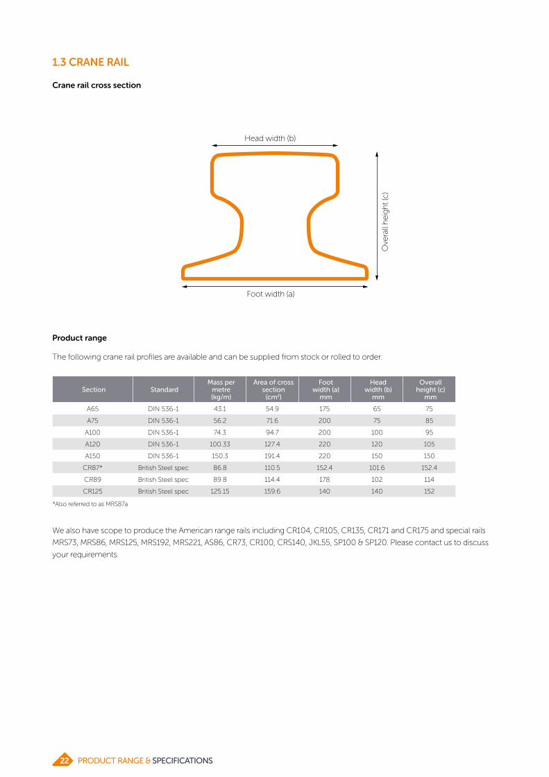
Crane rail cross section
Product range
The following crane rail profiles are available and can be supplied from stock or rolled to order.
We also have scope to produce the American range rails including CR104, CR105, CR135, CR171 and CR175 and special rails
MRS73, MRS86, MRS125, MRS192, MRS221, AS86, CR73, CR100, CRS140, JKL55, SP100 & SP120. Please contact us to discuss
your requirements.
Section StandardMass per
metre (kg/m)
Area of cross section
(cm2)
Foot width (a)
mm
Head width (b)
mm
Overall height (c)
mm
A65 DIN 536-1 43.1 54.9 175 65 75
A75 DIN 536-1 56.2 71.6 200 75 85
A100 DIN 536-1 74.3 94.7 200 100 95
A120 DIN 536-1 100.33 127.4 220 120 105
A150 DIN 536-1 150.3 191.4 220 150 150
CR87* British Steel spec 86.8 110.5 152.4 101.6 152.4
CR89 British Steel spec 89.8 114.4 178 102 114
CR125 British Steel spec 125.15 159.6 140 140 152
Foot width (a)
Ove
rall
hei
gh
t (c)
Head width (b)
*Also referred to as MRS87a
PRODUCT RANGE & SPECIFICATIONS22

1.3 CRANE RAIL
Grade Standard C Si Mn P S V Cr
690 DIN 536-1 Min 0.40 - 0.80 - - - -
Max 0.60 0.35 1.20 0.045 0.045 - -
880 DIN 536-1 Min 0.60 - 0.80 - - - -
Max 0.80 0.50 1.30 0.045 0.045 - -
90V British Steel spec Min 0.50 - 0.80 - - 0.06 -
Max 0.70 0.50 1.40 0.030 0.030 0.20 -
110CrV British Steel spec Min 0.65 0.15 0.90 - - 0.05 0.20
Max 0.85 0.30 1.30 0.030 0.030 0.15 0.80
DIN 536-1 BS
690 880 90V 1100V
A65
A75
A100
A120
A150
Crane rail 87
Crane rail 89
Crane rail 125
Grade capability by size
Ladle analysis
Mechanical testing
Tensile properties are determined in accordance with EN 10002-1. The minimum strength requirements are as follows:
Grade Minimum yield (MPa) Minimum UTS (MPa) Hardness (HBN)
690 355 690 204
880 440 880 260
90V 540 880 260
110CrV 600 1100 320
23PRODUCT RANGE & SPECIFICATIONS

1.4 CUTTING EDGE

1.4 CUTTING EDGE
For wear part applications
We produce a range of high-quality cutting edge profiles
providing additional wear resistance and extended life for
excavator bucket applications.
Customers can choose from an extensive range of ‘open roll’
profiles, or specify unique designs, where rolls and tooling
will be reserved for individual customer use. We can produce
many profile sizes and designs, including single bevels.
Our broad range of standard dimensions is produced on a
dependable rolling schedule meaning all sizes are regularly
available.
Our standard boron steel range:
• Offers high strength and toughness after heat treatment
• Can be used for ‘weld in’ applications
Our standard high carbon range:
• Offers lower tensile strength and toughness compared
with the boron range
• Particularly suitable for motor grader applications
25PRODUCT RANGE & SPECIFICATIONS

1.4 CUTTING EDGE
Product range
Single bevel flats
Profile Width mm (W)
Gaugemm (T)
WeightKg/m
Bevel angle
(A)
Bevel width
mm (B)
Tip heightmm (C)
SB244-25 244 25 44.46 22.6 45.60 6
SB244-30 244 30 54.07 22.6 45.60 11
SB244-32 244 32 57.91 22.6 45.60 13
SB281 281 32 65.00 22.6 57.60 8
SB299 299 40 85.25 22.6 72.00 10
SB304 304 44.45 97.40 22.6 69.10 15.7
We offer a wide variety of single and double bevel flats as
well as arrowhead and grader bar profiles suitable for a
broad range of bucket edge/blade applications.
W
TA
B
C
Profile Width mm (W)
Gaugemm (T)
WeightKg/m
Bevel width
mm (B)
Tip heightmm (C)
GB152-12 152.4 12.7 13.26 33.3 2.5
GB152-13 152.4 13.3 13.98 33.3 3.1
GB152-15 152.4 15.9 17.09 33.3 5.6
GB152-19 152.4 19.1 20.91 33.3 8.8
GB203-15 203.2 15.88 23.17 33.3 2.39
GB203-16 203.2 16.5 24.14 33.3 3.01
GB203-19 203.2 19.05 28.13 33.3 5.56
GB203-25 203.2 25.4 38.05 33.3 11.91
Profile Width mm (W)
Gaugemm (T)
WeightKg/m
Bevel angle
(A)
Bevel width
mm (B)
Tip heightmm (C)
AH203-19 203.2 19.1 31.40 24.3 60.3 4.6
AH203-22 203.2 22.2 36.50 24.3 60.3 7.7
AH203-25 203.2 25.4 41.62 24.3 60.3 10.9
AH203-28 203.2 28.6 46.73 24.3 60.3 14
AH203-31 203.2 31.8 51.84 24.3 60.3 17.2
AH255-28 255 28.5 65.65 25 98.7 11.2
AH255-40 255 40 88.66 25 98.7 22.7
T
W
B
C
W
TB
C
Grader bars (carbon and boron steel)
Arrowheads
PRODUCT RANGE & SPECIFICATIONS26

1.4 CUTTING EDGE
Double bevel flats
Profile Width mm (W)
Gaugemm (T)
WeightKg/m
Bevel angle
(A)
Bevel width
mm (B)
Tip heightmm (C)
DB203-16 203.2 16 23.79 25 23.60 5
DB203-19 203.2 19 28.53 25 23.60 8
DB203-22 203.2 22 33.28 25 23.60 11
DB203-25 203.2 25 38.02 25 23.60 14
DB203-28 203.2 28.5 43.55 25 23.60 17.5
DB254-19 254 19 35.37 25 27.90 6
DB254-25 254 25 47.25 25 27.90 12
DB254-29 254 29 55.16 25 27.90 16
DB254-32 254 32 61.10 25 27.90 19
DB254-35 254 35 67.04 25 27.90 22
DB254-38 254 38 72.97 25 27.90 25
DB254-41 254 41 78.91 25 27.90 28
DB254-45 254 45 86.83 25 27.90 32
DB279-25 279 25 48.08 22.5 45.90 6
DB279-35 279 35 70.02 22.5 45.90 16
DB305-22 305 22 48.63 22.5 37.40 6.5
DB305-25 305 25 55.76 22.5 37.40 9.5
DB305-28 305 28.5 64.09 22.5 37.40 13
DB305-30 305 30 67.66 22.5 37.40 14.5
DB305-32 305 32 72.42 22.5 37.40 16.5
DB305-35 305 35 79.56 22.5 37.40 19.5
DB305-38 305 38 86.69 22.5 37.40 22.5
DB305-41 305 41 93.83 22.5 37.40 25.5
DB305-44 305 44.5 102.15 22.5 37.40 29
DB330-19 330 19 45.73 22.5 32.60 5.5
DB330-22 330 22 53.45 22.5 32.60 8.5
DB330-25 330 25 61.18 22.5 32.60 11.5
DB330-28 330 28.5 70.19 22.5 32.60 15
DB330-30 330 30 74.06 22.5 32.60 16.5
DB330-32 330 32 79.02 22.5 32.60 18.5
Profile Width mm (W)
Gaugemm (T)
WeightKg/m
Bevel angle
(A)
Bevel width
mm (B)
Tip heightmm (C)
DB330-35 330 35 86.93 22.5 32.60 21.5
DB330-38 330 38 94.65 22.5 32.60 24.5
DB330-40 330 40 99.80 22.5 32.60 26.5
DB330-41 330 41 102.38 22.5 32.60 27.5
DB330-45 330 45 112.68 22.5 32.60 31.5
DB330-50 330 50 125.55 22.5 32.60 36.5
DB330-60 330 60 151.30 22.5 32.60 46.5
DB359-30 359 30 74.94 22.5 55.50 7
DB359-32 359 32 80.56 22.5 55.50 9
DB359-35 359 35 88.99 22.5 55.50 12
DB359-40 359 40 103.04 22.5 55.50 17
DB359-45 359 45 117.10 22.5 55.50 22
DB359-50 359 50 131.20 22.5 55.50 27
DB406-20 406 20 58.71 22.5 39.80 3.5
DB406-22 406 22 65.05 22.5 39.80 5.5
DB406-25 406 25 74.56 22.5 39.80 8.5
DB406-28 406 28.5 85.66 22.5 39.80 12
DB406-30 406 30 90.40 22.5 39.80 13.5
DB406-32 406 32 96.75 22.5 39.80 15.5
DB406-35 406 35 106.26 22.5 39.80 18.5
DB406-38 406 38 115.77 22.5 39.80 21.5
DB406-40 406 40 122.12 22.5 39.80 23.5
DB406-41 406 41 125.29 22.5 39.80 24.5
DB406-44 406 44.45 136.38 22.5 39.80 27.95
DB406-45 406 45 137.97 22.5 39.80 28.5
DB406-50 406 50 153.82 22.5 39.80 33.5
DB406-60 406 60 185.52 22.5 39.80 43.5
DB480-35 480 35 125.76 22.5 42.70 17.3
DB480-40 480 40 144.62 22.5 42.70 22.3
DB480-45 480 45 163.48 22.5 42.70 27.3
Notes: Please talk to us about the possibility of supplying alternative gauges and bevel angles to those shown. We can produce a range of thicknesses for the same bevel width.
W
AT
B
C
27PRODUCT RANGE & SPECIFICATIONS

1.4 CUTTING EDGE
Boron steel
We offer 3 boron-treated steels with a nominal carbon
content of 0.3%. Increasing levels of alloy content are
available to allow customers to match section thickness
and heat-treatment quench severity with hardenability. This
ensures a suitable core hardness is achieved in the finished
blade.
Steel specification Carbon (%) Chrome (%)
Standard carbon
C30Cr0 0.30 -
C30Cr15 0.30 0.15
C30Cr50 0.30 0.50
0mm
HRC0
60HRC
Jom
iny
har
dn
ess
Depth
C30Cr15
50mm
Hardenability curves - Boron steel (standard carbon content)
C30Cr50
C30Cr0
We recommend use of the following steel grades. They
are suitable for ‘weld in’ bucket edges as well as bolt-on
applications (appropriate weld procedure required).
Section Steel specification Carbon (%) Chrome (%)
AH203 C25Cr40 0.25 0.40
AH255 C20Cr50 0.20 0.50
Steel for arrowhead flats
PRODUCT RANGE & SPECIFICATIONS28

1.4 CUTTING EDGE
Boron steels with reduced carbon
A range of boron-treated steels is available with a lower
nominal carbon content of between 0.20% and 0.25%.
Heat-treatment of the blade improves toughness levels
without significant loss of hardness. The optimum
application of our standard and lower carbon range of
boron steels depends both on the section thickness and
on heat-treatment, particularly with respect to the quench
severity.
Steel specification Carbon (%) Chrome (%)
Lowcarbon
C20Cr50 0.20 0.50
C25Cr10 0.25 0.10
C25Cr40 0.25 0.40
C25Cr45 0.25 0.45
C25Cr75 0.25 0.75
C25Cr90 0.25 0.90
0mm
HRC0
60HRC
Jom
iny
har
dn
ess
Depth 50mm
Hardenability curves - Boron steel (reduced carbon content)
C25Cr75
C25Cr40
C25Cr45
C25Cr10
C20Cr50
C25Cr90
29PRODUCT RANGE & SPECIFICATIONS

1.5 FORKLIFT PROFILES

1.5 FORKLIFT PROFILES
Mast sections and fork arm flats for material handling equipment
We are a world-leading supplier with over 40 years’
experience in producing forklift truck components.
Our extensive range of products is used in everything from
the smallest warehouse truck to the largest container handler
and includes:
• Mast profiles – including U, I, J and offset J profiles
• Carriage (hanger) bar profiles
• Flats for manufacturing fork arms
• Our range includes ‘open’ roll profiles available to all
customers and for mast and carriage bar profiles; unique
‘bespoke’ profile designs where rolls and tooling are
reserved for exclusive customer use
We’re focused on achieving exceptional surface quality; a
£2m investment programme has enabled British Steel to
continue delivering products that satisfy the ever-increasing
demands of today’s marketplace.
31PRODUCT RANGE & SPECIFICATIONS

1.5 FORKLIFT PROFILES
Forklift mast profiles
World beating product capability
Size (mm) Kg/m
98 x 65 19.4
114 x 66 25.3
130 x 81 34.1
140 x 76 33.1
149 x 67 26.7
152 x 83 40.5
175 x 90 51.4
216 x 89 59.1
229 x 127 87.2
101 x 60* 17.8
140 x 70* 30.9
175 x 76* 42.0
Size (mm) Kg/m
121 x 41 20.9
135 x 53 28.6
157 x 61 35.9
166 x 65 19.8
175 x 66 42.9
201 x 71 52.3
252 x 90 78.5
145 x 48* 27.1
Size (mm) Kg/m
145 x 54 x 48 26.7
163 x 61 x 48 29.0
185 x 67 x 54 39.2
226 x 73 x 54 50.6
Size (mm) Kg/m
103 x 63 x 38 17.3
121 x 68 x 41 25.2
135 x 90 x 53 34.9
157 x 105 x 61 43.9
We manufacture a wide range of channel, beam, ‘J’ and ‘offset J’ and carriage bar sections for mast assembly.
Ongoing investment and continuous improvement in our processes are ensuring excellent shape, dimensional tolerances and surface quality.
Our range of low-carbon, high-strength, low-alloy steels is ideal for mast manufacture.
The open roll profile sizes below are illustrative of the wide range that we can produce (subject to tooling availability).
Channels
J & Offset J
Beams Special channels
We recognise the mast assembly as crucial to overall truck performance and work closely with our customers to develop the optimum mast shape and steel properties for every truck application.
Please contact us to discuss your specific requirements
PRODUCT RANGE & SPECIFICATIONS32

1.5 FORKLIFT PROFILES
Fork arm flats
Two standard steel specifications are available. They have different Jominy hardenability in order to ensure, after quenching and tempering, that mechanical properties can be achieved across the full range of thicknesses. Other steel specifications may be available on request.
Thickness (mm)
Width (mm)
100 120 122 123 150 180 200 230 250
35
40
45
50
55
60
65
70
75
80
85
90
95
100
105
110
115
120
125
130
135
140
145
150
C Cr Mn Mo B
C33Mo5 0.33 0.5 1.5 0.05 0.002
C30Mo17 0.30 0.5 1.2 0.17 0.002
Standard chemistries
Steel Specification
Yieldstrength
Tensile strength
Charpy at 20°C
Charpy at -20°C
C33Mo5 890 970 >47 >27
C30Mo17 950 1050 >47 >27
Typical mechanical properties post quench and temper
0
20
40
60
Depth (mm)
Jom
iny
har
dn
ess
(HR
C)
0 10
Hardenability curves
20 30 40 50
C33Mo5
C30Mo17
Key
Typically supplied in C33Mo5
Typically supplied in C30Mo17
Standard steel grades
Fork arm flats dimensional capability
33PRODUCT RANGE & SPECIFICATIONS

1.6 TOPHAT

1.6 TOPHAT
Shaft guides for mining applications
Our tophat shaft guides offer a high-quality, cost-effective
hoisting system for use in vertical mineshafts. They’re
designed to give maximum productivity and service life in
modern deep mine operations.
We have been working with the manufacturers of mining
equipment for many years and understand equipment must
be carefully designed and built to meet exacting demands.
Our unique open section tophat guides offer many benefits
including:
• Faster installation and replacement
• Pre-installation of butt strap connections
• Cost-effective installation
• Easier inspection and detection of defects
• 3 x longer life than alternative solutions
• Close-dimensional control and straightness, meaning
less swing in the shaft and a smoother lift
• Faster hoisting speeds due to their stiffness and higher
resistance to slamming forces
35PRODUCT RANGE & SPECIFICATIONS

1.6 TOPHAT
Standard dimensions
Size Weight Moduluslxx (cm4) A (mm) B (mm) C (mm) D (mm) E (mm)
232 x 98mm* 45.27kg/m 671 16 232 13.4 152 98
305 x 102mm 55.07kg/m 997 12.7 305 15.9 152 102
320 x 150mm 71.39kg/m 2815 13.5 320 18 150 150
340 x 175mm 85.94kg/m 4392 15 340 20 175 175
*Available under licence from Robor, contact us for more information
Standard steel grades:
• EN 10025-2: 2004, S355JR+AR, S355J2+AR
• SANS 50025-2: 2009, S355JR+AR, S355J2+AR
• CSA G40.21-04: 2004, 300W, 350W, 350WT
• AS/NZS 3679.1: Grade 350
All 4 sizes are offered with dimensions as follows:
• Straightness 5mm max over 12m length
• Twist 3mm max (typical < 1mm)
• Shaft guides are available in lengths from 6-17m,
with a cutting tolerance of +100/-0mm
• Cold sawn lengths are also available to suit individual
requirements, with a +0/-2mm cutting tolerance
B
CE
D
A
PRODUCT RANGE & SPECIFICATIONS36

1.6 TOPHAT
115
90
95
100
105
110
Hoisted mass Winding speed Fatigue life
Index
Key
Hollow section
British Steel tophat
*Based on 150 x 150 x 10 hollow section and 320 x 150 tophat
%
Relative performance
• The chart shows the superior performance of tophat
shaft guides relative to other guide rail sections on 3
different factors
• The analysis is based on the dynamic forces applied to
the shaft steelwork in the plane of the guides only
• Graph assumes all guide sections are used with the same
bunton spacing (i.e. shaft pocket spacing is already fixed)
37PRODUCT RANGE & SPECIFICATIONS

1.6 TOPHAT
Technical data
305x102mm (55.1kg/m) – SANS 50025:2 S355JR+AR
Centroid Centre of mass
Perimeter 941.042 X:152.36 X:152.36
Surface Area 7016.53 Y:50.7022 Y:50.7022
Mass 55.0278 Z:-1.62353e-014 Z:-1.62353e-014
Moments of inertia Products of inertia
Centre of mass
X:78195.5 XY:82.3751
Y:343178 XZ:9.9699e-014
Z:421374 YZ:1.43119e-012
Principal moments Principal directions
X:78195.5 1.000000 0.000311 0.000000
Y:343178 -0.000311 1.000000 0.000000
Z:421374 -0.000000 -0.000000 1.000000
Radii of gyration
X 37.6964
Y 78.9712
Z 87.507
232x98mm (45.27kg/m) – SANS 50025:2 S355JR+AR
Centroid Centre of mass
Perimeter 771.917 X:116.165 X:116.165
Surface area 5773.66 Y:54.6141 Y:54.6141
Mass 45.2805 Z:-1.0599e-019 Z:-1.0599e-019
Moments of inertia Products of inertia
Centre of mass
X:55768.9 XY:-30.0664
Y:212574 XZ:1.40654e-020
Z:4268343 YZ:-5.64846e-018
Principal moments Principal directions
X:55768.9 1.000000 0.000912 0.000000
Y:212574 0.000912 1.000000 -0.000000
Z:268343 -0.000000 0.000000 1.000000
Radii of gyration
X 35.0946
Y 68.5172
Z 76.892
PRODUCT RANGE & SPECIFICATIONS38

1.6 TOPHAT
Technical data
320x150mm (71.39kg/m) – SANS 50025:2 S355JR+AR
Centroid Centre of mass
Perimeter 1140.91 X:159.968 X:159.968
Surface Area 9046.97 Y:74.9227 Y:74.9227
Mass 70.9517 Z:-4.78417e-014 Z:-4.78417e-014
Moments of inertia Products of inertia
Centre of mass
X:220763 XY:136.929
Y:448707 XZ:-4.44512e-013
Z:669470 YZ:4.48865e-011
Principal moments Principal directions
X:220763 1.000000 0.000601 -0.000000
Y:448707 -0.000601 1.000000 0.000000
Z:669470 0.000000 -0.000000 1.000000
Radii of gyration
X 55.7804
Y 79.5243
Z 97.1369
340x175mm (85.94kg/m) – SANS 50025:2 S355JR+AR
Centroid Centre of mass
Perimeter 1273.97 X:170.000 X:170.000
Surface Area 1107.68 Y:-89.1562 Y:-89.1562
Mass 85.94 - -
Moments of inertia Products of inertia
Centre of mass
X:46099753.6 XY:0.0000
Y:83962559.1 -
- -
Principal moments Principal directions
X:46099753.6 1.000000 0.000000 -
Y:83962559.1 0.000000 1.000000 -
- - - -
Radii of gyration
X 64.4225
Y 86.9423
- -
39PRODUCT RANGE & SPECIFICATIONS

1.7 TRACKSHOE PROFILES

1.7 TRACKSHOE PROFILES
For enhanced crack-resistance and prolonged shoe life
We supply an extensive range of special profiles for the
manufacture of earthmoving equipment components.
Our range of ‘long bar’ profiles for track shoes is the most
comprehensive in the world.
We work closely with our customers in the earth moving
equipment industry, optimising both steel and design for
these demanding applications. Our proven track shoe
sections deliver benefits for heavy equipment performance
and customer processes.
Major benefits of our track shoe sections and related services
include:
• Prolonged shoe life – our low carbon and sulphur
steels deliver improved crack resistance – even in harsh
operating conditions
• Reliable quality – our ongoing investment in plant –
including superior straightening capability – delivers
products of reliable quality for fast and efficient
processing
• Improved process efficiency – our green track shoe
offers excellent pre-heat treatment mechanical
properties – so you can be confident of optimising your
process efficiency
• Fast response – short lead times and small batch sizes
(from as little as 130 tonnes) mean we can respond
swiftly to your needs
• Global support – we have vast experience in exporting
track shoes. Our well-established logistics chains
coupled with our international sales support network,
mean you can rely on us to deliver – wherever you are
41PRODUCT RANGE & SPECIFICATIONS

1.7 TRACKSHOE PROFILES
Product range
Section W (mm) H (mm) T (mm) Kg/m Link pitch (mm)
SG179 179 62.7 9.10 19.37 165.9
SG180 180 47.0 9.00 18.06 156.0
SG181 181 49.0 9.50 19.31 159.8
SG193 193 52.3 11.20 22.01 159.0
SG197-23 197 57.2 11.50 23.72 170.0
SG197-25 197 57.2 12.70 25.60 170.0
SG199 199 55.0 12.00 25.19 170.5
SG200 200 47.0 11.00 21.49 171.5
SG232 232 65.0 12.00 31.04 203.2
SG237 237 58.7 13.80 32.50 196.2
SG245 245 71.5 14.70 38.76 203.2
SG248-44 248 71.4 15.00 44.67 210.3
SG248-48 248 71.4 16.67 48.47 210.3
SG249-37 249 66.5 13.50 37.29 215.9
SG249-41 249 66.5 16.00 41.84 215.9
SG250 250 65.0 14.30 40.88 216.0
SG263-57 263 77.8 19.10 57.29 228.6
SG263-70 263 93.0 23.00 70.58 228.6
SG268-50 268 80.0 17.00 50.26 228.6
SG268-59 268 80.0 19.00 59.25 228.6
SG276 276 76.5 17.50 48.30 228.6
SG285-62 285 84.0 19.00 62.60 240.0
SG285-64 285 84.0 20.00 64.59 240.0
SG289 289 79.0 19.00 64.31 250.5
SG292 292 76.0 17.00 54.80 250.5
SG299 299 100.0 23.00 83.71 260.4
SG303 303 89.7 20.60 74.93 260.4
SG304 304 88.0 22.00 77.51 260.4
SG322 322 93.0 23.00 83.81 280.0
SG369 369 102.0 25.00 103.00 317.5
The track shoe profiles we produce are supplied in
customer lengths from 6m to 12m – lengths outside of this
range may be available on request. We also offer a variety of
different bundling configurations to suit your needs. Profile
widths range from 173mm to 369mm. Alternative gauges
may be available – please contact us to discuss your
requirements.
H
T
W
• Superior ground penetration for bulldozers
• General soil/rocky ground - depending on thickness of
profile
• Longer spike = improved traction
Single grousers
PRODUCT RANGE & SPECIFICATIONS42

1.7 TRACKSHOE PROFILES
Double grousers
Section W (mm) H (mm) T (mm) Kg/m Link pitch(mm)
DG202-26 202 31.0 11.5 26.17 172.5
DG202-28 202 31.0 13.0 28.39 172.5
DG217 217 35.0 13.0 33.04 190.5
DG250 250 37.0 16.5 48.12 216.0
DG252 252 49.0 15.5 50.17 216.0
DG308-71 308 49.5 21.0 71.90 258.5
DG308-80 308 49.5 25.0 80.17 258.5
H
T
W
• Good traction for loaders with less damage to ground
surface
• Shorter spikes = greater manoeuvrability
Section W (mm) H (mm) T (mm) Kg/mLink pitch (mm)
TG173 173 19.0 7.9 19.02 150.7
TG187 187 21.4 9.5 22.77 159.0
TG199-24 199 25.0 9.5 24.44 170.0
TG199-25 199 25.0 9.5 24.88 170.7
TG203-30 203 25.3 12.7 30.00 168.0
TG203-35 203 25.3 16.0 35.41 168.0
TG218 218 26.0 10.0 28.91 187.9
TG220-25 220 25.5 8.5 25.67 189.0
TG220-27 220 25.5 9.5 27.37 189.0
TG228-37 228 32.0 12.0 37.81 206.1
TG228-41 228 32.0 14.0 41.36 206.1
TG245-50 245 26.5 20.0 50.75 215.9
TG245-56 245 26.5 22.5 56.37 215.9
TG247 247 36.0 11.0 40.09 216.0
TG248 248 36.0 11.0 40.10 216.0
TG266 266 30.0 30.0 70.18 228.6
H
T
W
• Stable operating platform/improved manoeuvrability for
excavators
• Hard and soft ground applications
Triple grousers
43PRODUCT RANGE & SPECIFICATIONS

1.7 TRACKSHOE PROFILES
Standard steels
We offer a range of boron-treated steels with a nominal
carbon content of 0.3%. Increased levels of alloy content
are available to allow customers to match hardenability,
section size and heat treatment quench severity. This en-
sures the most suitable core hardness in the finished track
shoe.
Steel specification Carbon (%) Chrome (%)
Standard carbon
C30Cr0 0.30 -
C30Cr15 0.30 0.15
C30Cr50 0.30 0.50
0mm
HRC0
60HRC
Jom
iny
har
dn
ess
Depth
C30Cr15
50mm
Hardenability curves - standard carbon
C30Cr50
C30Cr0
PRODUCT RANGE & SPECIFICATIONS44

1.7 TRACKSHOE PROFILES
Lower carbon steels
A range of boron-treated steels is available with low sulphur
and/or a lower carbon content of 0.25%. This improves
crack resistance – prolonging shoe life and enhancing field
performance.
Steel specification Carbon (%) Chrome (%)
Lowcarbon
C25Cr10 0.25 0.10
C25Cr40 0.25 0.40
C25Cr45-LS 0.25 0.45
C25Cr75-LS 0.25 0.75
0mm
HRC0
60HRC
Jom
iny
har
dn
ess
Depth
C25Cr75-LS(Low sulphur)
C25Cr40
C25Cr45-LS (Low sulphur)
50mm
C25Cr10
Hardenability curves – low carbon
45PRODUCT RANGE & SPECIFICATIONS

1.8 MELTING BASE IRON (MBI)

1.8 MELTING BASE IRON (MBI)
For vacuum melted super alloys requirements
Our world-class steelmaking expertise provides the capability
to produce MBI (Melting Base Iron) products to meet the
exacting chemistry required by demanding sectors such as
Aerospace, Automotive and Oil & Gas.
With a long history of supply into the industry, we understand
the importance of delivering consistent chemistry.
We produce MBI in 250 casts which are then rolled into
75mm square billets in lengths from 6 to 12m. Excellent
dimensional control and straightness gives improved
stackability and our global reach means our products reach
our customers just when you need them.
Product range
Product Steel code C Si Mn P S Al
A iron Low manganese 9531 Min
5906 Max 0.004 0.006 0.05 0.004 0.004 0.005
B iron High manganese 9533 Min 0.12
5907 Max 0.008 0.004 0.18 0.008 0.008 0.008
47PRODUCT RANGE & SPECIFICATIONS

2 WIRE ROD

ABOUT WIRE RODWe produce a wide range of wire rod products for
markets including automotive, construction, engineering
and consumer goods. Our high-performance wire rod and
drawn wire meet the strict demands of a huge range of
applications, including fasteners, automotive springs, tyre
reinforcement, rail clips and bearings.
Our mills, based in Scunthorpe (UK) and Alblasserdam (the
Netherlands), have both received IATF 16949 certification
– the internationally-adopted quality management system
standard for the automotive industry.
We offer a flexible, responsive service, with dedicated
technical teams, customer support and local sales network.
Our technical team is always on hand to provide advice
on steel selection and processing, and our dedicated R&D
experts work in partnership with customers, universities and
research institutions to develop new and more advanced
grades of steel for increasingly demanding applications.
Thanks to our short-cycle rolling programmes and flexible
stock solutions, we can deliver precisely the steel you need
– just when you need it.
In addition to our mills manufacturing wire rod, our
Alblasserdam site also has a state-of-the-art wire processing
centre that produces annealed and pickled wire rod and
drawn wire for the global automotive, construction and
general engineering industries.
Rod Mill, Scunthorpe, UK Rod Mill and Wire Processing Centre, Alblasserdam, The
Netherlands
49PRODUCT RANGE & SPECIFICATIONS

2.1 COLD HEADING

2.1 COLD HEADING
High-performance wire and wire rod for fasteners and fixings
British Steel cold heading grades offer:
• Excellent hardenability and perform consistently in cold
forming and subsequent heat treatments, allowing
steel to be used to produce larger /higher strength
components (boron steels)
• Improved levels of ductility, formability and strength for
use in multiple applications (low carbon aluminium killed
steels)
We also offer:
• A dedicated short cycle rolling programme for a
comprehensive range of grades and sizes
• Technical expertise to support effective product selection
• Processing via our Wire Processing Centre, Albasserdam
The following tables indicate the typical chemical analysis for
British Steel’s cold heading grades. Other grades e.g. silicon-
killed can be considered and are available upon request.
Typical supplied chemical analysis (ladle) & tensile strength
Boron grades
Typical supplied chemical analysis (ladle) & tensile strength
Standard Grade C Si Mn P S Al Cr N Ti B UTS (MPa)
EN 10263-3 18B20.17-0.18
<0.100.75-0.80
<0.015 <0.0150.025-0.040
<0.05 <0.0090.020-0.040
0.002-0.004
440-500
22MnB40.21-0.22
<0.100.93-0.98
<0.015 <0.0150.025-0.040
<0.05 <0.0090.020-0.040
0.002-0.004
490-540
22MnB4+Cr0.22-0.23
<0.100.92-0.97
<0.015 <0.0150.025-0.040
0.25-0.30
<0.0090.020-0.040
0.002-0.004
520-580
EN 10263-4 17B20.17-0.18
<0.100.80-0.85
<0.015 <0.0150.025-0.040
<0.05 <0.0090.020-0.040
0.002-0.004
440-500
23B20.21-0.22
<0.100.83-0.88
<0.015 <0.0150.025-0.040
0.08-0.13
<0.0090.020-0.040
0.002-0.004
500-550
28B20.25-0.26
<0.100.85-0.90
<0.015 <0.0150.025-0.040
0.13-0.18
<0.0090.020-0.040
0.002-0.004
540-600
33B20.34-0.35
<0.100.60-0.65
<0.015 <0.0150.025-0.040
<0.05 <0.0090.020-0.040
0.002-0.004
520-580
38B2+Cr0.37-0.38
<0.100.76-0.80
<0.015 <0.0150.025-0.040
0.20-0.30
<0.0090.020-0.040
0.002-0.004
620-670
20MnB4*0.21- 0.22
<0.100.90- 1.00
<0.015 <0.0150.025- 0.040
<0.05 <0.0090.020- 0.040
0.002- 0.004
490-540
23MnB4*0.21-0.22
<0.100.90-1.00
<0.015 <0.0150.025-0.040
<0.05 <0.0090.020-0.040
0.002-0.004
490-540
30MnB4+Cr0.29- 0.31
<0.100.85- 0.90
<0.015 <0.0150.025- 0.040
0.15- 0.20
<0.0090.020- 0.040
0.002- 0.004
560-620
*Grades also available with chromium addition up to 0.3% max to meet customer requirements.
Wire rod dimensions
Rod diameter
Coil weight
Coil length
Coil dimensions
Note: Coil weight and length are dependent on rod diameter and grade combination. Specific coil package dimensions to be agreed at time of order placement/enquiry.
5.5 - 30.0mm in 0.5mm increments
1,800 - 2,200kg
1,000 - 1,700mm
Outside diameter: 1,300mm maxInside diameter: 800mm min
51PRODUCT RANGE & SPECIFICATIONS

Aluminium killed grades
Typical supplied chemical analysis (ladle) & tensile strength
Standard Grade C Si Mn P S Al Cr N UTS (MPa)
EN 10263-2 C4C0.04-0.05
<0.050.33-0.38
<0.015 <0.0150.030-0.050
<0.05 <0.006 350-390
C8C0.06-0.07
<0.050.33-0.38
<0.015 <0.0150.030-0.050
<0.05 <0.006 360-400
C10C0.10-0.11
<0.050.37-0.42
<0.015 <0.0150.030-0.050
<0.05 <0.006 380-420
C15C0.15-0.16
<0.050.50-0.55
<0.015 <0.0150.030-0.050
<0.05 <0.006 430-470
C17C0.18-0.19
<0.050.70-0.80
<0.015 <0.0150.030-0.050
<0.05 <0.006 470-520
C20C0.19-0.21
<0.050.75-0.85
<0.015 <0.0150.030-0.050
<0.05 <0.006 485-535
EN 10263-3 C10E2C0.10-0.11
<0.050.37-0.42
<0.015 <0.0150.030-0.050
<0.05 <0.006 380-420
C15E2C0.15-0.16
<0.050.50-0.55
<0.015 <0.0150.030-0.050
<0.05 <0.006 430-470
C17E2C0.18-0.19
<0.050.70-0.80
<0.015 <0.0150.030-0.050
<0.05 <0.006 470-520
Alloyed grades
Typical supplied chemical analysis (ladle) & tensile strength
Standard Grade C Si Mn P S Al Cr Mo B
EN 10263-4 37Cr40.34- 0.41
<0.100.60- 0.90
<0.025 <0.0250.020- 0.060
0.90- 1.20 - -
41Cr40.38- 0.45
<0.100.60-0.90
<0.025 <0.0250.020-0.060
0.90-1.20 - -
34CrMo40.30- 0.37
<0.100.60- 0.90
<0.025 <0.0250.020- 0.060
0.90- 1.20
0.15-0.30 -
30MoB10.28-0.32
<0.300.80- 1.00
<0.025 <0.0250.020-0.060
0.20-0.30
0.08-0.12
0.002-0.005
PRODUCT RANGE & SPECIFICATIONS52

2.2 FREECUTTING
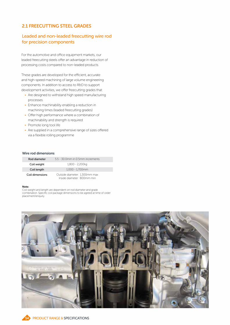
2.1 FREECUTTING STEEL GRADES
Leaded and non-leaded freecutting wire rod for precision components
For the automotive and office equipment markets, our
leaded freecutting steels offer an advantage in reduction of
processing costs compared to non-leaded products.
These grades are developed for the efficient, accurate
and high-speed machining of large volume engineering
components. In addition to access to R&D to support
development activities, we offer freecutting grades that:
• Are designed to withstand high speed manufacturing
processes
• Enhance machinability enabling a reduction in
machining times (leaded freecutting grades)
• Offer high performance where a combination of
machinability and strength is required
• Promote long tool life
• Are supplied in a comprehensive range of sizes offered
via a flexible rolling programme
Wire rod dimensions
Rod diameter
Coil weight
Coil length
Coil dimensions
5.5 - 30.0mm in 0.5mm increments
1,800 - 2,200kg
1,000 - 1,700mm
Outside diameter: 1,300mm maxInside diameter: 800mm min
Note: Coil weight and length are dependent on rod diameter and grade combination. Specific coil package dimensions to be agreed at time of order placement/enquiry.
PRODUCT RANGE & SPECIFICATIONS54

2.1 FREECUTTING STEEL GRADES
Leaded freecutting grades
Non-leaded freecutting grades
Typical supplied chemical analysis (ladle)
Standard Grade C Si Mn P S Pb N
EN ISO 683-4 11SMnPb300.07-0.09
<0.011.00-1.05
0.05-0.07
0.28-0.32
0.26-0.29
-
11SMnPb30 (High Pb + N)
0.07-0.09
<0.011.05-1.10
0.05-0.07
0.28-0.32
0.29-0.33
0.009-0.012
11SMnPb370.07-0.09
<0.011.20-1.30
0.06-0.08
0.35-0.39
0.28-0.33
0.007-0.012
36SMnPb140.33-0.36
0.15-0.19
1.45-1.55
0.025 max
0.10-0.14
0.20-0.25
-
EN ISO 683-3 C15Pb0.13-0.15
0.20-0.25
0.40-0.50
0.025 max
0.020-0.030
0.20-0.25
-
EN ISO 683-1 C45Pb0.44-0.48
0.20-0.25
0.60-0.70
0.020 max
0.020- 0.040
0.20-0.25
0.012max
AISI/SAE 12L140.07-0.09
<0.011.00-1.05
0.05-0.07
0.28-0.32
0.26-0.29
-
Typical supplied chemical analysis (ladle)
Standard Grade C Si Mn P S N Cr
EN ISO 683-4 11SMn300.07-0.09
<0.010.98-1.02
0.05-0.07
0.27-0.31
- -
11SMn370.07-0.09
<0.011.20-1.30
0.06-0.08
0.35-0.39
0.007-0.012
-
38SMn280.36-0.38
0.15-0.20
1.30-1.40
0.025 max
0.27-0.30
-0.07-0.10
44SMn280.42-0.43
0.20-0.25
1.55-1.60
0.025 max
0.27-0.30
- -
46S200.44-0.47
0.15-0.20
1.00-1.05
0.025 max
0.18-0.22
-0.12-0.17
AISI/SAE 11440.42-0.43
0.20-0.25
1.55-1.60
0.025 max
0.27-0.30
- -
12150.07-0.09
<0.010.98-1.02
0.05-0.07
0.27-0.31
- -
The following tables indicate the typical chemical analysis
for British Steel’s freecutting grades. Other grades can be
considered and are available upon request.
55PRODUCT RANGE & SPECIFICATIONS

2.3 TYRE REINFORCEMENT

The table below indicates the typical chemical analysis
limits for our tyre reinforcement grades. Other grades and
analysis limits can be considered upon request. Typical tensile
strengths and reduction of area are displayed, however these
can be tailored through process route optimisation.
Steel grade
Grade C Si Mn P S N Cr Tensile (MPa)
Reduction of area (%)
62C 0.62 – 0.65 0.19 – 0.22 0.48 – 0.53 ≤0.011 ≤0.011 ≤0.006 – 920 ≥46
72C 0.71 – 0.75 0.19 – 0.22 0.48 – 0.52 ≤0.014 ≤0.009 ≤0.006 – 1030 ≥40
84C 0.81 – 0.84 0.19 – 0.22 0.48 – 0.51 ≤0.013 ≤0.012 ≤0.006 – 1120 ≥37
95C+Cr 0.90 – 0.95 0.19 – 0.22 0.33 – 0.37 ≤0.014 ≤0.009 ≤0.006 0.20 –0.24 1260 ≥37
2.3 TYRE REINFORCEMENT STEEL GRADES
Steel products for tyre reinforcement
For the automotive market, our tyre cord wire rod provides a
tyre with strength, shape and durability, as well as improving
performance and longevity. We produce high-strength
steel for the production of tyre cord that can be tailored to
individual customer specifications:
• Tensile strength can be altered by adapting the steel
microstructure
• Scale characteristics can be tailored to meet the
customers’ preferred method of descaling
For tyre cord and tyre bead customers, we offer:
• Technical expertise and responsiveness
• A non-integrated supply chain allowing our customers
to plan their workload and collaborate with us to develop
bespoke tailored solutions
Wire rod dimensions
Rod diameter
Coil weight
Coil length
Coil dimensions
5.5 mm
1,800 - 2,200kg
1,350 - 1,700mm
Outside diameter: 1,250mm maxInside diameter: 850mm min
Note: Standard tyre reinforcement wire rod dimensional tolerances: Gauge +/-0.20mm, ovality 0.30mm max
57PRODUCT RANGE & SPECIFICATIONS

2.4 AUTOMOTIVE SPRING STEEL

The table below indicates the typical chemical analysis levels
for our automotive spring steel grades.
Note: Sizes available subject to technical referral
Standard Grade C Si Mn P S Cr V
EN 10089 54SiCr6 0.52 – 0.56 1.40 – 1.50 0.60 – 0.70 < 0.015 < 0.010 0.60 – 0.70 -
54SiCrV6 0.53 – 0.57 1.35 – 1.45 0.60 – 0.70 < 0.015 < 0.010 0.52 – 0.62 0.10/0.15
2.4 AUTOMOTIVE SPRING STEEL
Carbon alloy wire rod for oil-tempered automotive springs
The production of suspension springs requires super clean
consistent quality steel. These springs are in constant motion
when in use in safety-critical applications.
For our Automotive customers, our spring steel products offer
2 main advantages: reliability and short delivery lead time. This
is in addition to:
• Rigorous testing to meet customers stringent
requirements
• A comprehensive size range to satisfy automotive
requirements
• Access to dedicated technical expertise
Wire rod dimensions
Rod diameter
Coil weight
Coil length
Coil dimensions
5.5 - 30.0mm in 0.5mm increments
1,800 - 2,200kg
1,000 - 1,700mm
Outside diameter: 1,300mm maxInside diameter: 800mm min
Note: Coil weight and length are dependent on rod diameter and grade combination. Specific coil package dimensions to be agreed at time of order placement/enquiry.
59PRODUCT RANGE & SPECIFICATIONS

2.5 RAIL CLIP

The table below indicates the typical chemical analysis levels
for British Steel’s spring steel grades for rail clip applications.
Standard Grade C Si Mn P S Cr V
Wsn 1.5023Acc. EN 10089
38Si7 0.35-0.42 1.50-1.80 0.50-0.80 Max 0.025 Max 0.025 Max 0.30 Max 0.10
2.5 RAIL CLIP
High-performance wire rod for rail clip applications
For the rail industry our dedicated technical team and
responsive global sales team offer support to meet the
exacting requirements of rail clip applications.
Our 38SiCr7 offers:
• Uniform microstructure to facilitate downstream
processing
• Dimensional accuracy and surface quality
• Can also be supplied in annealed and/or drawn
condition
Rail clip image courtesy of Pandrol
Wire rod dimensions
Rod diameter
Coil weight
Coil length
Coil dimensions
5.5 – 16mm
800 – 2,200kg
Max 1,400mm
Outside diameter: 1,300mm maxInside diameter: 800mm min
As-rolled properties:
• Material has a uniform ferrite/pearlite structure
• Tensile Strength: Rm = 700-850 MPa
• Reduction of Area: Z = min 50%
61PRODUCT RANGE & SPECIFICATIONS

2.6 BEARING STEEL

2.6 BEARING STEEL GRADES
Bearing wire rod and wire grades for processing into balls, rollers, needles and axles
Bearings demand clean, fatigue-resistant wire rod and wire
with consistent properties to ensure reliable long life. Our
bearing grades are:
• Manufactured and tested to ensure steel cleanliness,
hardenability, dimensional stability and enhanced
formability
• Manufactured using a range of steel making routes
to ensure we meet the requirements of demanding
applications
Wire rod dimensions
Rod diameter
Coil weight
Coil length
Coil dimensions
5.5 - 30.0mm in 0.5mm increments
1,800kg
1,000 - 1,300mm
Outside diameter: 1,300mm maxInside diameter: 800mm min
Wire diameter
Note:Coil size, weight and length are dependent on final size and execution and are available on request. See our Wire Processing Centre datasheet for further information.
1.8 - 29.0mm
Drawn wire dimensions
63PRODUCT RANGE & SPECIFICATIONS
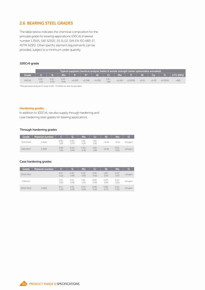
Through hardening grades
Hardening grades
In addition to 100Cr6, we also supply through hardening and
case hardening steel grades for bearing applications.
Case hardening grades
Grade Material number C Si Mn Cr Ni Mo O
100CrMn6 1.35200.93- 1.05
0.40-0.70
1.00- 1.20
1.40- 1.65
<0.30 <0.10 <15 ppm
100CrMo7 1.35370.93- 1.05
0.20- 0.40
0.25- 0.45
1.65- 1.95
<0.300.15- 0.25
<15 ppm
Grade Material number C Si Mn Cr Ni Mo O
20NiCrMo70.17- 0.22
0.20- 0.40
0.45- 0.65
0.40- 0.60
1.60- 2.00
0.20- 0.30
<15 ppm
17MnCr50.15- 0.20
0.15- 0.40
1.00- 1.40
0.40- 0.80
0.20- 0.50
0.10-0.20
<15 ppm
20NiCrMo2 1.65220.17- 0.23
0.15- 0.30
0.70- 0.90
0.40- 0.60
0.40- 0.70
0.15- 0.30
<15 ppm
2.6 BEARING STEEL GRADES
The table below indicates the chemical composition for the
principal grade for bearing applications 100Cr6 (material
number 1.3505, SAE 52100, JIS SUJ2, DIN EN ISO 683-17,
ASTM A295). Other specific element requirements can be
provided, subject to a minimum order quantity.
100Cr6 grade
*Resulphurised analyses (S range 0.015 - 0.030%) can also be provided.
Typical supplied chemical analysis (ladle) & tensile strength (when spheroidise annealed)
Grade C Si Mn P S* Al Cr Mo Ti Ni Cu O UTS (MPa)
100Cr60.93 - 1.05
0.15 - 0.35
0.25 - 0.45
<0.025 <0.008 <0.0501.35 - 1.60
<0.010 <0.0030 <0.25 <0.30 <0.0009 <680
PRODUCT RANGE & SPECIFICATIONS64

2.7 WELDING STEEL

The table below indicates our representative welding wire
grades. Other grades can be considered and are available
upon request.
*Wire rod for low and medium alloyed welding consumables can be supplied in custom made batches of 30 tonnes min.
Type Standard Grade Material number
MIG / MAG
SG 1 EN ISO 14341 - 2Si 10MnSi5 1.5112
SG 2 EN ISO 14341 - 3Si1 11MnSi6 1.5125
SG 3 EN ISO 14341 - 4Si1 10MnSi7 1.5130
Electrodes
E EN ISO 2560 RSD 7 1.0324
Sub-merged arc welding
S1 EN ISO 14171 - S1 RRSD 10 1.0351
S2Si EN ISO 14171 - S2Si 11MN4Si 1.0492
S3 EN ISO 14171 - S3 12Mn6 1.0496
S2Mo EN ISO 14171 - S2Mo 11MnMo4 5 1.5425
Low and medium alloyed*
MnSi + Ti 13Mn12 1.5089
CrMo AWS ER 80S-B2 11CrMo5 1.7339
MnCrMo AWS ER S-D2 13MnMo 1.5428
NiMnMo AWS ER 80S-Ni2 11NiMnMo4-5 1.6312
AWS ER 100S-G 5NiMnMo8
CrMoSi AWS ER 90S-B3 9CrMoSi10
Welding wire rod for processing into welding electrodes, MIG / MAG (gas-shielded metal arc) electrodes and submerged arc welding wires
We specialise in wire rod for low and medium alloyed special
welding consumables.
• Steel can be further processed by both pickling and
mechanical descaling for the optimum surface finish
• More alloyed grades can be delivered in the annealed
condition to ensure good drawability
Wire rod dimensions
Rod diameter
Coil weight
Coil length
Coil dimensions
Note: Alternative coil weights and dimensions are available on request.
5.5 - 10.0mm in 0.5mm increments
1,800 - 2,000kg (steel base dependent)
1,000 - 1,400mm
Outside diameter: 1,300mm maxInside diameter: 850mm min
2.7 WELDING STEEL
PRODUCT RANGE & SPECIFICATIONS66

2.7 WELDING STEEL
Additions in titanium, zirconium, copper and vanadium may be available upon request.
Cr Ni Mo Si Mn
Max w-% 6 4 1 2 2
Additional alloys
We can also offer steels with additional alloys up to the
maximum content limits in the table below. Please contact us
to discuss your requirements.
1) Tighter limits possible, to be checked upon request2) With reservation, depending on alloy content certain residual elements can be different3) Product analysis limits upon request
P S Cr Mo Ni V Ti Cu Pb Sn As
Max w-% 0.012 0.015 0.10 0.04 0.10 0.01 0.002 0.15 0.01 0.008 0.008
Maximum possible residual element limits in ladle analysis 1),2),3)
Nb Ca Co Zr Sb W Al B Ta N O
Max w-% 0.005 0.001 0.010 0.005 0.005 0.005 0.010 0.0003 0.015 0.007 0.0025
67PRODUCT RANGE & SPECIFICATIONS

2.8 HIGH TENSIILE

The table below indicates typical as-rolled tensiles, other
grades can be considered upon request.
Steel grades
Grade Typical carbon %
Significantalloys
Typical tensile strength in 12mm as-rolled rod
(N/mm2)
Typical reduction of area (%)
M83B 0.8 V 1180 ≥30
M85B 0.83 V 1220 ≥30
M90B 0.88 V 1260 ≥25
X85Cr 0.83 Cr 1200 ≥30
X95Cr 0.93 Cr 1220 ≥25
M94Si 0.92 Si, Cr 1370 ≥25
2.8 HIGH TENSILE
High strength-to-weight ratio wire rod for bridge and deepwater cables
High-tensile bridge and deepwater cables require consistent
quality wire rod with high strength to weight ratio. The
enhanced strength-to-weight ratio of our high tensile wire
rod enables cable cross-sections to be reduced and delivers:
• Reduced cable and superstructure weight (including
cable bands, clamps, hanger cables and saddles)
• Reduced cable installation and spinning time
• Reduced construction programme
• Overall project cost savings
We offer:
• Flexible rolling programme
• Support of a dedicated technical team and experienced
global sales network
• Technical expertise and R&D facilities to support
collaborative development projects
Wire rod dimensions
Rod diameter
Coil weight
Coil length
Coil dimensions
5.5 - 15.0mm in 0.5mm increments
1,800 - 2,200kg
1,350 - 1,700mm
Outside diameter: 1,250mm maxInside diameter: 850mm min
Note:Sizes available subject to technical referral
69PRODUCT RANGE & SPECIFICATIONS

2.9 WIRE PROCESSING CENTRE

2.9 WIRE PROCESSING CENTRE
Drawing, pickling and annealing to enhance your wire rod and wire products
Our Alblasserdam site produces annealed and pickled wire
rod and drawn wire for the global automotive, construction
and general engineering industries.
Annealing
To make wire rod more workable, we offer spheroidised
annealing, recrystallisation annealing and stress-relief
annealing. Our annealing programmes are specifically
designed for our different grades.
Pickling
Where surface quality is critical, scale can be removed by
hydrochloric acid. We also offer a variety of coatings to further
optimise processing e.g. lime, salt carrier, phosphate and
soap for drawing and flat-rolling or phosphate and soap or
polymer for cold forming and cold extrusion.
Drawing
For downstream processes that require smaller diameters
and/or tighter size tolerances, our drawing plant produces
drawn wire in a wide variety of grades.
Coil properties
Notes:Can be delivered in as rolled, annealed and/or pickled, coated. Coil weight and length are dependent on rod diameter and grade combination. Specific coil package dimensions to be agreed at time of order placement/enquiry.
Rod diameter 5.5 - 30.0mm in 0.5mm increments
Coil weight 1,800 - 2,200kg
Coil length 1,000 - 1,700mm
Coil dimensions Outside diameter: 1,300mm
Inside diameter: 800mm
Tolerance In accordance with EN 10108 A or B
Wire rod dimensions
The table below indicates the typical specifications for our
wire rod range, inclusive of material treated via annealing and/
or pickling.
71PRODUCT RANGE & SPECIFICATIONS

2.9 WIRE PROCESSING CENTRE
Strapping 4 band straps
Labels / tags (as rolled) 1 plastic with barcode & plain text and 1 metal tag with text
Labels / tags (treated wire rod) 1 plastic with barcode as standard (second label available on request)
Coil handling
Drawn wire dimensions
Diameter 1.8 - 28.0mm
Tolerance In accordance with EN 10278:1999 (h9, h10 or h11 possible)
Notes: Available in coils, spooled coils, and on spiders/carriers in a variety of weights and make up - options are dependent on final execution and size). Can be delivered in as drawn, annealed (or combination), coated with phosphate or soap
Treatment conditions
EN DIN Description
+U+C K Drawn
+AC+C GKZ+K Annealed-drawn
+U+C+AC K+GKZ Drawn-annealed
+U+C+AC+LC K+GKZ+K Drawn-annealed-drawn
+AC+C+AC+LC GKZ+K+GKZ+K Annealed-drawn-annealed-drawn
PRODUCT RANGE & SPECIFICATIONS72

3 CONSTRUCTION

ABOUT CONSTRUCTIONWe supply a wide range of structural sections to the
construction industry. Our sections have constructed
some of the most iconic buildings and bridges around the
world.
Produced in the UK, our products are CE marked and tested
to the highest standards, providing quality and reassurance
to the global construction market.
As the only UK manufacturer of heavy sections, we have 2
mills, as well as further processing facilities, which enable
us to offer a comprehensive product range. This includes
bespoke sections, which are rolled frequently.
Standard dimensions are supplied in the as-rolled condition
from our mills in Scunthorpe and Teesside, and can be shot-
blasted and primed.
Supported by our sales offices around the world, we take
pride in offering high levels of customer service and quality
products that are manufactured and delivered to customers’
exact requirements.
In line with Construction Products Regulations (CPR),
material used in construction must have a test certificate
showing results at the appropriate test temperature, supplied
by a CPR-registered manufacturer such as British Steel.
Our full section range is tested in accordance with the
requirements of BS EN10025-2 and is legally compliant with
CPR.
PRODUCT RANGE & SPECIFICATIONS74

3.1 UK SECTIONS

3.1 UK SECTIONS
Universal Beams
Material to EN 10025-2Nominal dimensions to EN 10365:2017 (where applicable) Tolerance EN 10034:1993
Designation
Serial size
Mass per metre
kg/m
Depth of
section
Width of
section
Thickness Root radius Depth between
filletsof web of flange
D B t T r d
mm mm mm mm mm mm
127 x 76 x 13 13.0 127.0 76.0 4.0 7.6 7.6 96.6
152 x 89 x 16 16.0 152.4 88.7 4.5 7.7 7.6 121.8
178 x 102 x 19 19.0 177.8 101.2 4.8 7.9 7.6 146.8
203 x 102 x 23 23.1 203.2 101.8 5.4 9.3 7.6 169.4
203 x 133 x 25 25.1 203.2 133.2 5.7 7.8 7.6 172.4
203 x 133 x 30 30.0 206.8 133.9 6.4 9.6 7.6 172.4
254 x 102 x 22 22.0 254.0 101.6 5.7 6.8 7.6 225.2
254 x 102 x 25 25.2 257.2 101.9 6.0 8.4 7.6 225.2
254 x 102 x 28 28.3 260.4 102.2 6.3 10.0 7.6 225.2
254 x 146 x 31 31.1 251.4 146.1 6.0 8.6 7.6 219.0
254 x 146 x 37 37.0 256.0 146.4 6.3 10.9 7.6 219.0
254 x 146 x 43 43.0 259.6 147.3 7.2 12.7 7.6 219.0
305 x 102 x 25 24.8 305.1 101.6 5.8 7.0 7.6 275.9
305 x 102 x 28 28.2 308.7 101.8 6.0 8.8 7.6 275.9
305 x 102 x 33 32.8 312.7 102.4 6.6 10.8 7.6 275.9
305 x 127 x 37 37.0 304.4 123.4 7.1 10.7 8.9 265.2
305 x 127 x 42 41.9 307.2 124.3 8.0 12.1 8.9 265.2
305 x 127 x 48 48.1 311.0 125.3 9.0 14.0 8.9 265.2
305 x 165 x 40 40.3 303.4 165.0 6.0 10.2 8.9 265.2
305 x 165 x 46 46.1 306.6 165.7 6.7 11.8 8.9 265.2
305 x 165 x 54 54.0 310.4 166.9 7.9 13.7 8.9 265.2
356 x 171 x 45 45.0 351.4 171.1 7.0 9.7 12.7 306.6
356 x 171 x 51 51.0 355.0 171.5 7.4 11.5 12.7 306.6
356 x 171 x 57 57.0 358.0 172.2 8.1 13.0 12.7 306.6
356 x 171 x 67 67.1 363.4 173.2 9.1 15.7 12.7 306.6
406 x 140 x 39 39.0 398.0 141.8 6.4 8.6 12.7 355.4
406 x 140 x 46 46.0 403.2 142.2 6.8 11.2 12.7 355.4
406 x 140 x 53 53.3 406.6 143.3 7.9 12.9 12.7 355.4
406 x 178 x 54 54.1 402.6 177.7 7.7 10.9 12.7 355.4
406 x 178 x 60 60.1 406.4 177.9 7.9 12.8 12.7 355.4
406 x 178 x 67 67.1 409.4 178.8 8.8 14.3 12.7 355.4
406 x 178 x 74 74.2 412.8 179.5 9.5 16.0 12.7 355.4
406 x 178 x 85 85.3 417.2 181.9 10.9 18.2 12.7 355.4
457 x 152 x 52 52.3 449.8 152.4 7.6 10.9 12.7 402.6
457 x 152 x 60 59.8 454.6 152.9 8.1 13.3 12.7 402.6
457 x 152 x 67 67.2 458.0 153.8 9.0 15.0 12.7 402.6
457 x 152 x 74 74.2 462.0 154.4 9.6 17.0 12.7 402.6
457 x 152 x 82 82.1 465.8 155.3 10.5 18.9 12.7 402.6
457 x 191 x 67 67.1 453.4 189.9 8.5 12.7 12.7 402.6
457 x 191 x 74 74.3 457.0 190.4 9.0 14.5 12.7 402.6
457 x 191 x 82 82.0 460.0 191.3 9.9 16.0 12.7 402.6
457 x 191 x 89 89.3 463.4 191.9 10.5 17.7 12.7 402.6
D
B
d
rt
T
p16 - Advance® UK Beams
PRODUCT RANGE & SPECIFICATIONS76

3.1 UK SECTIONS
Universal Beams (continued)
D
B
d
rt
T
p16 - Advance® UK Beams
Designation
Serial size
Mass per metre
kg/m
Depth of
section
Width of
section
Thickness Root radius Depth between
filletsof web of flange
D B t T r d
mm mm mm mm mm mm
457 x 191 x 98 98.3 467.2 192.8 11.4 19.6 12.7 402.6
457 x 191 x 106 105.8 469.2 194.0 12.6 20.6 12.7 402.6
457 x 191 x 133 133.3 480.6 196.7 15.3 26.3 12.7 402.6
457 x 191 x 161 161.4 492.0 199.4 18.0 32.0 12.7 402.6
533 x 165 x 66 65.7 524.7 165.1 8.9 11.4 12.7 476.5
533 x 165 x 74 74.7 529.1 165.9 9.7 13.6 12.7 476.5
533 x 165 x 85 84.8 534.9 166.5 10.3 16.5 12.7 476.5
533 x 210 x 82 82.2 528.3 208.8 9.6 13.2 12.7 476.5
533 x 210 x 92 92.1 533.1 209.3 10.1 15.6 12.7 476.5
533 x 210 x 101 101.0 536.7 210.0 10.8 17.4 12.7 476.5
533 x 210 x 109 109.0 539.5 210.8 11.6 18.8 12.7 476.5
533 x 210 x 122 122.0 544.5 211.9 12.7 21.3 12.7 476.5
533 x 210 x 138 138.3 549.1 213.9 14.7 23.6 12.7 476.5
533 x 312 x 150 150.6 542.5 312.0 12.7 20.3 12.7 476.5
533 x 312 x 182 181.5 550.7 314.5 15.2 24.4 12.7 476.5
533 x 312 x 219 218.7 560.3 317.4 18.3 29.2 12.7 476.5
533 x 312 x 272 273.2 577.1 320.2 21.1 37.6 12.7 476.5
610 x 178 x 82 81.8 598.6 177.9 10.0 12.8 20.0 533.0
610 x 178 x 92 92.2 603.0 178.8 10.9 15.0 20.0 533.0
610 x 178 x 100 100.3 607.4 179.2 11.3 17.2 20.0 533.0
610 x 229 x 101 101.2 602.6 227.6 10.5 14.8 20.0 533.0
610 x 229 x 113 113.0 607.6 228.2 11.1 17.3 20.0 533.0
610 x 229 x 125 125.1 612.2 229.0 11.9 19.6 20.0 533.0
610 x 229 x 140 139.9 617.2 230.2 13.1 22.1 20.0 533.0
610 x 305 x 149 149.2 612.4 304.8 11.8 19.7 20.0 533.0
610 x 305 x 179 179.0 620.2 307.1 14.1 23.6 20.0 533.0
610 x 305 x 238 238.1 635.8 311.4 18.4 31.4 20.0 533.0
686 x 254 x 125 125.2 677.9 253.0 11.7 16.2 20.0 605.5
686 x 254 x 140 140.1 683.5 253.7 12.4 19.0 20.0 605.5
686 x 254 x 152 152.4 687.5 254.5 13.2 21.0 20.0 605.5
686 x 254 x 170 170.2 692.9 255.8 14.5 23.7 20.0 605.5
762 x 267 x 134 133.9 750.0 264.4 12.0 15.5 20.0 679.0
762 x 267 x 147 146.9 754.0 265.2 12.8 17.5 20.0 679.0
762 x 267 x 173 173.0 762.2 266.7 14.3 21.6 20.0 679.0
762 x 267 x 197 196.8 769.8 268.0 15.6 25.4 20.0 679.0
838 x 292 x 176 175.9 834.9 291.7 14.0 18.8 20.0 757.3
838 x 292 x 194 193.8 840.7 292.4 14.7 21.7 20.0 757.3
838 x 292 x 226 226.5 850.9 293.8 16.1 26.8 20.0 757.3
914 x 305 x 201 200.9 903.0 303.3 15.1 20.2 19.1 824.4
914 x 305 x 224 224.2 910.4 304.1 15.9 23.9 19.1 824.4
914 x 305 x 253 253.4 918.4 305.5 17.3 27.9 19.1 824.4
914 x 305 x 289 289.1 926.6 307.7 19.5 32.0 19.1 824.4
77PRODUCT RANGE & SPECIFICATIONS

3.1 UK SECTIONS
Universal Beams (continued)
Designation
Serial size
Mass per metre
kg/m
Depth of
section
Width of
section
Thickness Root radius Depth between
filletsof web of flange
D B t T r d
mm mm mm mm mm mm
914 x 419 x 343 343.3 911.8 418.5 19.4 32.0 24.1 799.6
914 x 419 x 388 388.0 921.0 420.5 21.4 36.6 24.1 799.6
1016 x 305 x 222 222.0 970.3 300.0 16.0 21.1 30.0 868.1
1016 x 305 x 249 248.7 980.1 300.0 16.5 26.0 30.0 868.1
1016 x 305 x 272 272.3 990.1 300.0 16.5 31.0 30.0 868.1
1016 x 305 x 314 314.3 999.9 300.0 19.1 35.9 30.0 868.1
1016 x 305 x 349 349.4 1008.1 302.0 21.1 40.0 30.0 868.1
1016 x 305 x 393 392.7 1015.9 303.0 24.4 43.9 30.0 868.1
1016 x 305 x 437 437.0 1026.1 305.4 26.9 49.0 30.0 868.1
1016 x 305 x 487 486.7 1036.3 308.5 30.0 54.1 30.0 868.1
D
B
d
rt
T
p16 - Advance® UK Beams
PRODUCT RANGE & SPECIFICATIONS78
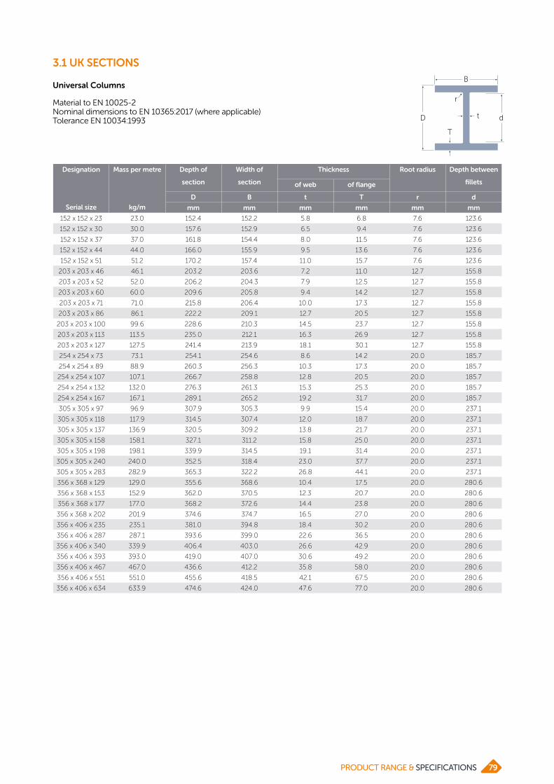
Universal Columns
Material to EN 10025-2Nominal dimensions to EN 10365:2017 (where applicable) Tolerance EN 10034:1993
3.1 UK SECTIONS
Designation
Serial size
Mass per metre
kg/m
Depth of
section
Width of
section
Thickness Root radius Depth between
filletsof web of flange
D B t T r d
mm mm mm mm mm mm
152 x 152 x 23 23.0 152.4 152.2 5.8 6.8 7.6 123.6
152 x 152 x 30 30.0 157.6 152.9 6.5 9.4 7.6 123.6
152 x 152 x 37 37.0 161.8 154.4 8.0 11.5 7.6 123.6
152 x 152 x 44 44.0 166.0 155.9 9.5 13.6 7.6 123.6
152 x 152 x 51 51.2 170.2 157.4 11.0 15.7 7.6 123.6
203 x 203 x 46 46.1 203.2 203.6 7.2 11.0 12.7 155.8
203 x 203 x 52 52.0 206.2 204.3 7.9 12.5 12.7 155.8
203 x 203 x 60 60.0 209.6 205.8 9.4 14.2 12.7 155.8
203 x 203 x 71 71.0 215.8 206.4 10.0 17.3 12.7 155.8
203 x 203 x 86 86.1 222.2 209.1 12.7 20.5 12.7 155.8
203 x 203 x 100 99.6 228.6 210.3 14.5 23.7 12.7 155.8
203 x 203 x 113 113.5 235.0 212.1 16.3 26.9 12.7 155.8
203 x 203 x 127 127.5 241.4 213.9 18.1 30.1 12.7 155.8
254 x 254 x 73 73.1 254.1 254.6 8.6 14.2 20.0 185.7
254 x 254 x 89 88.9 260.3 256.3 10.3 17.3 20.0 185.7
254 x 254 x 107 107.1 266.7 258.8 12.8 20.5 20.0 185.7
254 x 254 x 132 132.0 276.3 261.3 15.3 25.3 20.0 185.7
254 x 254 x 167 167.1 289.1 265.2 19.2 31.7 20.0 185.7
305 x 305 x 97 96.9 307.9 305.3 9.9 15.4 20.0 237.1
305 x 305 x 118 117.9 314.5 307.4 12.0 18.7 20.0 237.1
305 x 305 x 137 136.9 320.5 309.2 13.8 21.7 20.0 237.1
305 x 305 x 158 158.1 327.1 311.2 15.8 25.0 20.0 237.1
305 x 305 x 198 198.1 339.9 314.5 19.1 31.4 20.0 237.1
305 x 305 x 240 240.0 352.5 318.4 23.0 37.7 20.0 237.1
305 x 305 x 283 282.9 365.3 322.2 26.8 44.1 20.0 237.1
356 x 368 x 129 129.0 355.6 368.6 10.4 17.5 20.0 280.6
356 x 368 x 153 152.9 362.0 370.5 12.3 20.7 20.0 280.6
356 x 368 x 177 177.0 368.2 372.6 14.4 23.8 20.0 280.6
356 x 368 x 202 201.9 374.6 374.7 16.5 27.0 20.0 280.6
356 x 406 x 235 235.1 381.0 394.8 18.4 30.2 20.0 280.6
356 x 406 x 287 287.1 393.6 399.0 22.6 36.5 20.0 280.6
356 x 406 x 340 339.9 406.4 403.0 26.6 42.9 20.0 280.6
356 x 406 x 393 393.0 419.0 407.0 30.6 49.2 20.0 280.6
356 x 406 x 467 467.0 436.6 412.2 35.8 58.0 20.0 280.6
356 x 406 x 551 551.0 455.6 418.5 42.1 67.5 20.0 280.6
356 x 406 x 634 633.9 474.6 424.0 47.6 77.0 20.0 280.6
D
B
dt
T
r
p20 - Advance® UK Columns
79PRODUCT RANGE & SPECIFICATIONS

Universal Bearing Piles
Material to EN 10025-2Nominal dimensions to EN 10365:2017 (where applicable) Tolerance EN 10034:1993 D
B
dt
T
r
p20 - Advance® UK Columns
Designation
Serial size
Mass per metre
kg/m
Depth of
section
Width of
section
Thickness Root radius Depth between
filletsof web of flange
D B t T r d
mm mm mm mm mm mm
203 x 203 x 45 44.9 200.2 205.9 9.5 9.5 10.2 160.8
203 x 203 x 54 53.9 204.0 207.7 11.3 11.4 10.2 160.8
254 x 254 x 63 63.0 247.1 256.6 10.6 10.7 20.0 185.7
254 x 254 x 71 71.0 249.7 258.0 12.0 12.0 20.0 185.7
254 x 254 x 85 85.1 254.3 260.4 14.4 14.3 20.0 185.7
305 x 305 x 79 78.9 299.3 306.4 11.0 11.1 20.0 237.1
305 x 305 x 88 88.0 301.7 307.8 12.4 12.3 20.0 237.1
305 x 305 x 95 94.9 303.7 308.7 13.3 13.3 20.0 237.1
305 x 305 x 110 110.0 307.9 310.7 15.3 15.4 20.0 237.1
305 x 305 x 126 126.1 312.3 312.9 17.5 17.6 20.0 237.1
305 x 305 x 149 149.1 318.5 316.0 20.6 20.7 20.0 237.1
305 x 305 x 186 186.0 328.3 320.9 25.5 25.6 2.0 273.1
305 x 305 x 223 222.9 337.9 325.7 30.3 30.4 20.0 237.1
356 x 368 x 109 108.9 346.4 371.0 12.8 12.9 20.0 280.6
356 x 368 x 133 133.0 352.0 373.8 15.6 15.7 20.0 280.6
356 x 368 x 152 152.0 356.4 376.0 17.8 17.9 20.0 280.6
356 x 368 x 174 173.9 361.4 378.5 20.3 20.4 20.0 280.6
3.1 UK SECTIONS
PRODUCT RANGE & SPECIFICATIONS80

Parallel Flange Channels
Material to EN 10025-2Nominal dimensions to EN 10365:2017 (where applicable)Tolerance EN 10279:2000
3.1 UK SECTIONS
Designation
Serial size
Mass per metre
kg/m
Depth of
section
Width of
section
Thickness Root radius Depth between
filletsof web of flange
D B t T r d
mm mm mm mm mm mm
100 x 50 x 10 10.2 100 50 5.0 8.5 9 65
125 x 65 x 15 14.8 125 65 5.5 9.5 12 82
150 x 75 x 18 17.9 150 75 5.5 10.0 12 106
150 x 90 x 24 23.9 150 90 6.5 12.0 12 102
180 x 75 x 20 20.3 180 75 6.0 10.5 12 135
180 x 90 x 26 26.1 180 90 6.5 12.5 12 131
200 x 75 x 23 23.4 200 75 6.0 12.5 12 151
200 x 90 x 30 29.7 200 90 7.0 14.0 12 148
230 x 75 x 26 25.7 230 75 6.5 12.5 12 181
230 x 90 x 32 32.2 230 90 7.5 14.0 12 178
260 x 75 x 28 27.6 260 75 7.0 12.0 12 212
260 x 90 x 35 34.8 260 90 8.0 14.0 12 208
300 x 90 x 41 41.4 300 90 9.0 15.5 12 245
300 x 100 x 46 45.5 300 100 9.0 16.5 15 237
380 x 100 x 54 54.0 380 100 9.5 17.5 15 315
430 x 100 x 64 64.4 430 100 11.0 19.0 15 362
D
B
dt
T
r
p24 - Advance® UK Parallel Flange Channels
81PRODUCT RANGE & SPECIFICATIONS
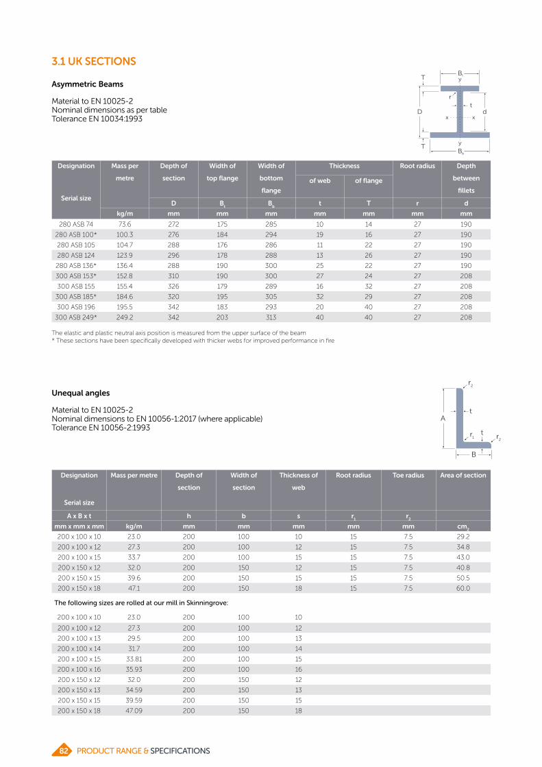
Asymmetric Beams
Material to EN 10025-2Nominal dimensions as per table Tolerance EN 10034:1993
Designation
Serial size
Mass per
metre
Depth of
section
Width of
top flange
Width of
bottom
flange
Thickness Root radius Depth
between
fillets
of web of flange
D Bt
Bb
t T r d
kg/m mm mm mm mm mm mm mm
280 ASB 74 73.6 272 175 285 10 14 27 190
280 ASB 100* 100.3 276 184 294 19 16 27 190
280 ASB 105 104.7 288 176 286 11 22 27 190
280 ASB 124 123.9 296 178 288 13 26 27 190
280 ASB 136* 136.4 288 190 300 25 22 27 190
300 ASB 153* 152.8 310 190 300 27 24 27 208
300 ASB 155 155.4 326 179 289 16 32 27 208
300 ASB 185* 184.6 320 195 305 32 29 27 208
300 ASB 196 195.5 342 183 293 20 40 27 208
300 ASB 249* 249.2 342 203 313 40 40 27 208
The elastic and plastic neutral axis position is measured from the upper surface of the beam* These sections have been specifically developed with thicker webs for improved performance in fire
y
p26 - Asymmetric Slimflor® Beams
B
B
x x
y
b
t
T
T
d
r
Dt
Unequal angles
Material to EN 10025-2Nominal dimensions to EN 10056-1:2017 (where applicable)Tolerance EN 10056-2:1993
Designation
Serial size
Mass per metre Depth of
section
Width of
section
Thickness of
web
Root radius Toe radius Area of section
A x B x t h b s r1
r2
mm x mm x mm kg/m mm mm mm mm mm cm2
200 x 100 x 10 23.0 200 100 10 15 7.5 29.2
200 x 100 x 12 27.3 200 100 12 15 7.5 34.8
200 x 100 x 15 33.7 200 100 15 15 7.5 43.0
200 x 150 x 12 32.0 200 150 12 15 7.5 40.8
200 x 150 x 15 39.6 200 150 15 15 7.5 50.5
200 x 150 x 18 47.1 200 150 18 15 7.5 60.0
The following sizes are rolled at our mill in Skinningrove:
200 x 100 x 10 23.0 200 100 10
200 x 100 x 12 27.3 200 100 12
200 x 100 x 13 29.5 200 100 13
200 x 100 x 14 31.7 200 100 14
200 x 100 x 15 33.81 200 100 15
200 x 100 x 16 35.93 200 100 16
200 x 150 x 12 32.0 200 150 12
200 x 150 x 13 34.59 200 150 13
200 x 150 x 15 39.59 200 150 15
200 x 150 x 18 47.09 200 150 18
p32 - Advance® UK Angles Unequal Angles
A
B
t
t
r1 r2
r2
3.1 UK SECTIONS
PRODUCT RANGE & SPECIFICATIONS82

3.1 UK SECTIONS
Equal angles
Material to EN 10025-2Nominal dimensions to EN 10056-1:2017 (where applicable)Tolerance EN 10056-2:1993
p30 - Advance® UK Angles Equal Angles
A
A
t
t
90°
r1 r2
Designation
Serial size
Mass per metre Depth of
section
Width of
section
Thickness Root radius Toe radius Area of
section
A x A x t h b s r1
r2
mm x mm x mm kg/m mm mm mm mm mm cm2
120 x 120 x 8 14.7 120 120 8 13 6.5 18.7
120 x 120 x 10 18.2 120 120 10 13 6.5 23.2
120 x 120 x 12 21.6 120 120 12 13 6.5 27.5
120 x 120 x 15 26.6 120 120 15 13 6.5 33.9
150 x 150 x 10 23.0 150 150 10 16 8.0 29.3
150 x 150 x 12 27.3 150 150 12 16 8.0 34.8
150 x 150 x 15 33.8 150 150 15 16 8.0 43.0
150 x 150 x 18 40.1 150 150 18 16 8.0 51.0
200 x 200 x 16 48.5 200 200 16 18 9.0 61.8
200 x 200 x 18 54.2 200 200 18 18 9.0 69.1
200 x 200 x 20 59.9 200 200 20 18 9.0 76.3
200 x 200 x 24 71.1 200 200 24 18 9.0 90.6
The following sizes are rolled at our mill in Skinningrove:
200 x 200 x 14 42.7 200 200 14
200 x 200 x 15 45.7 200 200 15
200 x 200 x 16 48.5 200 200 16
200 x 200 x 17 51.4 200 200 17
200 x 200 x 18 54.2 200 200 18
200 x 200 x 19 57.1 200 200 19
200 x 200 x 20 59.9 200 200 20
200 x 200 x 22 65.6 200 200 22
200 x 200 x 23 68.4 200 200 23
200 x 200 x 24 71.1 200 200 24
200 x 200 x 25 73.9 200 200 25
200 x 200 x 26 76.6 200 200 26
200 x 200 x 28 82.0 200 200 28
200 x 200 x 28.6 200 200 28.6
200 x 200 x 30 87.4 200 200 30
200 x 200 x 32 200 200 32
200 x 200 x 34 98.0 200 200 34
250 x 250 x 24 90.0 250 250 24
250 x 250 x 25 93.5 250 250 25
250 x 250 x 26 97.6 250 250 26
250 x 250 x 27 100.5 250 250 27
250 x 250 x 28 104.0 250 250 28
250 x 250 x 32 118.0 250 250 32
250 x 250 x 35 128.0 250 250 35
83PRODUCT RANGE & SPECIFICATIONS

Designation
Serial size
Mass per metre Depth of
section
Width of
section
Thickness of
web
Root radius Toe radius Area of section
A x B x t h b s r1
r2
mm x mm x mm kg/m mm mm mm
inches
mm mm cm2
203 x 203 x 12.7 39.3 203 203 12.71/2
203 x 203 x 14.3 203 203 14.39/16
203 x 203 x 15.9 48.7 203 203 15.95/8
203 x 203 x 19 57.9 203 203 193/4
203 x 203 x 22.2 67.0 203 203 22.27/8
203 x 203 x 25.4 75.9 203 203 25.41
203 x 203 x 28.6 84.94 203 203 28.61 1/8
Imperial range (rolled at Skinningrove)
3.1 UK SECTIONS
Equal angles (continued)
p30 - Advance® UK Angles Equal Angles
A
A
t
t
90°
r1 r2
PRODUCT RANGE & SPECIFICATIONS84

3.2 AMERICAN SECTIONS

3.2 AMERICAN SECTIONS
American wide flange beams (W)
Material to ASTM A572 Grade 50 and ASTM A992Nominal dimensions to ASTM A6 (where applicable)Tolerance ASTM A6
Designation
serial size
Mass
per
foot
ASTM metric
equivalent
Depth of
section
Width of
section
Thickness Root radius Depth
between
filletsof web of flange
h b tw
tf
r d
in lb/ft mm mm mm mm mm mm
W 6 x 6 15 W 150 x 150 x 22.5 152 152 5.8 6.6 10.0 118.8
W 6 x 6 20 W 150 x 150 x 29.8 157 153 6.6 9.3 10.0 118.4
W 6 x 6 25 W 150 x 150 x 37.1 162 154 8.1 11.6 10.0 118.8
W 8 x 5.25 18 W 200 x 135 x 26.6 207 133 5.8 8.4 10.0 170.2
W 8 x 5.25 21 W 200 x 135 x 31.3 210 134 6.4 10.2 10.0 169.6
W 8 x 8 31 W 200 x 200 x 46.1 203 203 7.2 11.0 10.4 160.2
W 8 x 8 35 W 200 x 200 x 52 206 204 7.9 12.6 10.4 160.0
W 8 x 8 40 W 200 x 200 x 59 210 205 9.1 14.2 10.4 160.8
W 8 x 8 48 W 200 x 200 x 71 216 206 10.2 17.4 10.4 160.4
W 8 x 8 58 W 200 x 200 x 86 222 209 13.0 20.6 10.4 160.0
W 8 x 8 67 W 200 x 200 x 100 229 210 14.5 23.7 10.4 160.8
W 8 x 8 76* W 200 x 200 x 113 235 212.1 16.3 26.9 10.4 160.4
W 8 x 8 86* W 200 x 200 x 128 241.4 213.9 18.1 30.1 10.4 160.4
W 10 x 4 15 W 250 x 100 x 22.3 254 102 5.8 6.9 10.0 220.2
W 10 x 4 17 W 250 x 100 x 25.3 257 102 6.1 8.4 10.0 220.4
W 10 x 4 19 W 250 x 100 x 28.4 260 102 6.4 10.0 10.0 220.4
W 10 x 5.75 22 W 250 x 145 x 32.7 258 146 6.1 9.1 10.0 220.1
W 10 x 5.75 26 W 250 x 145 x 38.5 262 147 6.6 11.2 10.0 220.0
W 10 x 5.75 30 W 250 x 145 x 44.8 266 148 7.6 13.0 10.0 219.9
W 10 x 10 49 W 250 x 250 x 73 253 254 8.6 14.2 20.0 184.6
W 10 x 10 54 W 250 x 250 x 80 256 255 9.4 15.6 20.0 184.8
W 10 x 10 60 W 250 x 250 x 89 260 256 10.7 17.3 20.0 185.4
W 10 x 10 68 W 250 x 250 x 101 264 257 11.9 19.6 20.0 184.8
W 10 x 10 72* W 250 x 250 x 107 266.7 258.8 12.8 20.5 20.0 185.7
W 10 x 10 77 W 250 x 250 x 115 269 259 13.5 22.1 20.0 184.8
W 10 x 10 88 W 250 x 250 x 131 275 261 15.4 25.1 20.0 184.8
W 10 x 10 100 W 250 x 250 x 149 282 263 17.3 28.4 20.0 185.2
W 10 x 10 112 W 250 x 250 x 167 289 265 19.2 31.8 20.0 185.4
W 12 x 4 16 W 310 x 100 x 23.8 305 101 5.6 6.7 10.0 271.6
W 12 x 4 19 W 310 x 100 x 28.3 309 102 6.0 8.9 10.0 271.2
W 12 x 4 22 W 310 x 100 x 32.7 313 102 6.6 10.8 10.0 271.4
W 12 x 12 65 W 310 x 310 x 97 308 305 9.9 15.4 20.0 237.2
W 12 x 12 72 W 310 x 310 x 107 311 306 10.9 17.0 20.0 237.0
W 12 x 12 79 W 310 x 310 x 117 314 307 11.9 18.7 20.0 236.6
W 12 x 12 87 W 310 x 310 x 129 318 308 13.1 20.6 20.0 236.8
W 12 x 12 92* W 310 x 310 x 137 320.5 309.2 13.8 21.7 20.0 237.1
W 12 x 12 96 W 310 x 310 x 143 323 309 14.0 22.9 20.0 237.2
W 12 x 12 106 W 310 x 310 x 158 327 310 15.5 25.1 20.0 236.8
W 12 x 12 120 W 310 x 310 x 179 333 313 18.0 28.1 20.0 236.8
W 12 x 12 133* W 310 x 310 x 198 339.9 314.5 19.1 31.4 20.0 237.1
W 12 x 12 136 W 310 x 310 x 202 341 315 20.1 31.8 20.0 237.4
W 12 x 12 152 W 310 x 310 x 226 348 317 22.1 35.6 20.0 236.8
*Non-ASTM weight, but still offered by British Steel.
PRODUCT RANGE & SPECIFICATIONS86

3.2 AMERICAN SECTIONS
American wide flange beams (W) (continued)
Designation
serial size
Mass per
foot
ASTM metric
equivalent
Depth of
section
Width of
section
Thickness Root radius Depth
between
filletsof web of flange
h b tw
tf
r d
in lb/ft mm mm mm mm mm mm
W 12 x 12 161* W 310 x 310 x 240 352.5 318.4 23.0 37.7 20.0 237.1
W 12 x 12 170 W 310 x 310 x 253 356 319 24.4 39.6 20.0 236.8
W 12 x 12 190 W 310 x 310 x 283 365 322 26.9 44.1 20.0 236.8
W 14 x 6.75 30 W 360 x 170 x 44.6 352 171 6.9 9.8 12.7 307.0
W 14 x 6.75 34 W 360 x 170 x 51 355 171 7.2 11.6 12.7 306.4
W 14 x 6.75 38 W 360 x 170 x 58 358 172 7.9 13.1 12.7 306.4
W 14 x 6.75 45* W 360 x 170 x 67 363.4 173.2 9.1 15.7 12.7 306.6
W 14 x 14.5 87* W 360 x 370 x 129 355.6 368.6 10.4 17.5 20.0 280.6
W 14 x 14.5 90 W 360 x 370 x 134 356 369 11.2 18.0 20.0 280.0
W 14 x 14.5 99 W 360 x 370 x 147 360 370 12.3 19.8 20.0 280.4
W 14 x 14.5 103* W 360 x 370 x 153 362 370.5 12.3 20.7 20.0 280.6
W 14 x 14.5 109 W 360 x 370 x 162 364 371 13.3 21.8 20.0 280.4
W 14 x 14.5 119* W 360 x 370 x 177 368.2 372.6 14.4 23.8 20.0 280.6
W 14 x 14.5 120 W 360 x 370 x 179 368 374 15.0 23.9 20.0 280.2
W 14 x 14.5 132 W 360 x 370 x 196 372 374 16.4 26.2 20.0 279.6
W 14 x 14.5 136* W 360 x 370 x 202 374.6 374.7 16.5 27.0 20.0 280.6
W 14 x 16 145 W 360 x 410 x 216 375 394 17.3 27.7 20.0 279.6
W 14 x 16 158* W 360 x 410 x 235 381 394.8 18.4 30.2 20.0 280.6
W 14 x 16 159 W 360 x 410 x 237 380 395 18.9 30.2 20.0 279.6
W 14 x 16 176 W 360 x 410 x 262 387 398 21.1 33.3 20.0 280.4
W 14 x 16 193 W 360 x 410 x 287 393 399 22.6 36.6 20.0 279.8
W 14 x 16 211 W 360 x 410 x 314 399 401 24.9 39.6 20.0 279.8
W 14 x 16 228* W 360 x 410 x 340 406.4 403 26.6 42.9 20.0 280.6
W 14 x 16 233 W 360 x 410 x 347 407 404 27.2 43.7 20.0 279.6
W 14 x 16 257 W 360 x 410 x 382 416 406 29.8 48.0 20.0 280.0
W 14 x 16 264* W 360 x 410 x 393 419 407 30.6 49.2 20.0 280.6
W 14 x 16 283 W 360 x 410 x 421 425 409 32.8 52.6 20.0 279.8
W 14 x 16 311 W 360 x 410 x 463 435 412 35.8 57.4 20.0 280.2
W 14 x 16 314* W 360 x 410 x 467 436.6 412.2 35.8 58.0 20.0 280.6
W 14 x 16 320* W 360 x 410 x 477 427 424.4 48.0 53.6 20.0 279.8
W 14 x 16 342 W 360 x 410 x 509 446 416 39.1 62.7 20.0 280.6
W 14 x 16 370 W 360 x 410 x 551 455 418 42.0 67.6 20.0 279.8
W 14 x 16 398 W 360 x 410 x 592 465 421 45.0 72.3 20.0 280.4
W 14 x 16 426 W 360 x 410 x 634 474 424 47.6 77.1 20.0 279.8
W 14 x 16 455 W 360 x 410 x 677 483 428 51.2 81.5 20.0 280.0
W 14 x 16 500 W 360 x 410 x 744 498 432 55.6 88.9 20.0 280.2
W 14 x 16 550 W 360 x 410 x 818 514 437 60.5 97.0 20.0 280.0
W 14 x 16 605 W 360 x 410 x 900 531 442 65.9 106.0 20.0 279.0
W 14 x 16 665 W 360 x 410 x 990 550 448 71.9 115.0 20.0 280.0
W 14 x 16 730 W 360 x 410 x 1086 569 454 78.0 125.0 20.0 279.0
W 16 x 5.5 26 W 410 x 140 x 38.8 403 140 6.4 8.8 12.7 360.0
W 16 x 5.5 31 W 410 x 140 x 46.1 403 140 7.0 11.2 12.7 355.2
*Non-ASTM weight, but still offered by British Steel
87PRODUCT RANGE & SPECIFICATIONS

3.2 AMERICAN SECTIONS
American wide flange beams (W) (continued)
Designation
serial size
Mass per
foot
ASTM metric
equivalent
Depth of
section
Width of
section
Thickness Root radius Depth
between
filletsof web of flange
h b tw
tf
r d
in lb/ft mm mm mm mm mm mm
W 16 x 5.5 35* W 410 x 140 x 53 406.6 143.3 7.9 12.9 12.7 355.4
W 16 x 7 36 W 410 x 180 x 53 403 177 7.5 10.9 12.7 355.8
W 16 x 7 40 W 410 x 180 x 60 407 178 7.7 12.8 12.7 356.0
W 16 x 7 45 W 410 x 180 x 67 410 179 8.8 14.4 12.7 355.8
W 16 x 7 50 W 410 x 180 x 75 413 180 9.7 16.0 12.7 355.6
W 16 x 7 57 W 410 x 180 x 85 417.0 181.0 10.9 18.2 12.7 355.2
W 18 x 6 35 W 460 x 150 x 52 450 152 7.6 10.8 12.7 403.0
W 18 x 6 40 W 460 x 150 x 60 455 153 8.0 13.3 12.7 403.0
W 18 x 6 46 W 460 x 150 x 68 459 154 9.1 15.4 12.7 402.8
W 18 x 6 50* W 460 x 150 x 74 462 154.4 9.6 17.0 12.7 402.6
W 18 x 6 55* W 460 x 150 x 82 465.8 155.3 10.5 18.9 12.7 402.6
W 18 x 7.5 45* W 460 x 190 x 67 453.4 189.9 8.5 12.7 12.7 402.6
W 18 x 7.5 50 W 460 x 190 x 74 457 190 9.0 14.5 12.7 402.6
W 18 x 7.5 55 W 460 x 190 x 82 460 191 9.9 16.0 12.7 402.6
W 18 x 7.5 60 W 460 x 190 x 89 463 192 10.5 17.7 12.7 402.2
W 18 x 7.5 65 W 460 x 190 x 97 466 193 11.4 19.0 12.7 402.6
W 18 x 7.5 71 W 460 x 190 x 106 469 194 12.6 20.6 12.7 402.4
W 18 x 7.5 89* W 460 x 190 x 133 480.6 196.7 15.3 26.3 12.7 402.6
W 18 x 7.5 108* W 460 x 190 x 161 492 199.4 18.0 32.0 12.7 402.6
W 18 x 11 76 W 460 x 280 x 113 463 280 10.8 17.3 20.0 388.4
W 18 x 11 86 W 460 x 280 x 128 467 282 12.2 19.6 20.0 387.8
W 18 x 11 97 W 460 x 280 x 144 472 283 13.6 22.1 20.0 387.8
W 18 x 11 106 W 460 x 280 x 158 476 284 15.0 23.9 20.0 388.2
W 18 x 11 119 W 460 x 280 x 177 482 286 16.6 26.9 20.0 388.2
W 18 x 11 130 W 460 x 280 x 193 489 283 17.0 30.5 20.0 388.0
W 18 x 11 143 W 460 x 280 x 213 495 285 18.5 33.5 20.0 388.0
W 18 x 11 158 W 460 x 280 x 235 501 287 20.6 36.6 20.0 387.8
W 18 x 11 175 W 460 x 280 x 260 509 289 22.6 40.4 20.0 388.2
W 18 x 11 192 W 460 x 280 x 286 517 291 24.4 44.4 20.0 388.2
W 18 x 11 211 W 460 x 280 x 315 525 293 26.9 48.5 20.0 388.0
W 21 x 6.5 44 W 530 x 165 x 66 525 165 8.9 11.4 12.7 476.8
W 21 x 6.5 50 W 530 x 165 x 74 529 166 9.7 13.6 12.7 476.4
W 21 x 6.5 57 W 530 x 165 x 85 535 166 10.3 16.5 12.7 476.6
W 21 x 8.25 55 W 530 x 210 x 82 528 209 9.5 13.3 12.7 476.0
W 21 x 8.25 62 W 530 x 210 x 92 533 209 10.2 15.6 12.7 476.4
W 21 x 8.25 68 W 530 x 210 x 101 537 210 10.9 17.4 12.7 476.8
W 21 x 8.25 73 W 530 x 210 x 109 539 211 11.6 18.8 12.7 476.0
W 21 x 8.25 83 W 530 x 210 x 123 544 212 13.1 21.2 12.7 476.2
W 21 x 8.25 93 W 530 x 210 x 138 549 214 14.7 23.6 12.7 476.4
W 21 x 12.25 101 W 530 x 310 x 150 543 312 12.7 20.3 12.7 477.0
W 21 x 12.25 111 W 530 x 310 x 165 546 313 14.0 22.2 12.7 476.2
W 21 x 12.25 122 W 530 x 310 x 182 551 315 15.2 24.4 12.7 476.8
*Non-ASTM weight, but still offered by British Steel
PRODUCT RANGE & SPECIFICATIONS88

Designation
serial size
Mass per
foot
ASTM metric
equivalent
Depth of
section
Width of
section
Thickness Root radius Depth
between
filletsof web of flange
h b tw
tf
r d
in lb/ft mm mm mm mm mm mm
W 21 x 12.25 132 W 530 x 310 x 196 554 316 16.5 26.3 12.7 476.0
W 21 x 12.25 147 W 530 x 310 x 219 560 318 18.3 29.2 12.7 476.2
W 21 x 12.25 166 W 530 x 310 x 248 571 315 19.0 34.5 12.7 476.6
W 21 x 12.25 182 W 530 x 310 x 272 577 317 21.1 37.6 12.7 476.4
W 24 x 7 55 W 610 x 182 x 82 599 178 10.0 12.8 20.0 533.4
W 24 x 7 62 W 610 x 182 x 92 603 179 10.9 15.0 20.0 533.0
W 24 x 7 67* W 610 x 182 x 100 607 179.2 11.3 17.2 20.0 532.6
W 24 x 9 68 W 610 x 230 x 101 603 228 10.5 14.9 20.0 533.2
W 24 x 9 76 W 610 x 230 x 113 608 228 11.2 17.3 20.0 533.4
W 24 x 9 84 W 610 x 230 x 125 612 229 11.9 19.6 20.0 532.8
W 24 x 9 94 W 610 x 230 x 140 617 230 13.1 22.2 20.0 532.6
W 24 x 12 100* W610 x 300 x 149 612.4 304.8 11.8 19.7 20.0 533.0
W 24 x 12 120* W 610 x 300 x 179 620.2 307.1 14.4 23.6 20.0 533.0
W 24 x 12 160* W 610 x 300 x 238 635.8 311.4 18.4 31.4 20.0 533.0
W 24 x 12.75 104 W 610 x 325 x 155 611 324 12.7 19.0 20.0 533.0
W 24 x 12.75 117 W 610 x 325 x 174 616 325 14.0 21.6 20.0 532.8
W 24 x 12.75 131 W 610 x 325 x 195 622 327 15.4 24.4 20.0 533.2
W 24 x 12.75 146 W 610 x 325 x 217 628 328 16.5 27.7 20.0 532.6
W 24 x 12.75 162 W 610 x 325 x 241 635 329 17.9 31.0 20.0 533.0
W 24 x 12.75 176 W 610 x 325 x 262 641 327 19.0 34.0 20.0 533.0
W 24 x 12.75 192 W 610 x 325 x 285 647 329 20.6 37.1 20.0 532.8
W 24 x 12.75 207 W 610 x 325 x 307 653 330 22.1 39.9 20.0 533.2
W 24 x 12.75 229 W 610 x 325 x 341 661 333 24.4 43.9 20.0 533.2
W 24 x 12.75 250 W 610 x 325 x 372 669 335 26.4 48.0 20.0 533.0
W 27 x 10 84 W 690 x 250 x 125 678 253 11.7 16.3 20.0 605.4
W 27 x 10 94 W 690 x 250 x 140 684 254 21.4 18.9 20.0 606.2
W 27 x 10 102 W 690 x 250 x 152 688 254 13.1 21.1 20.0 605.8
W 27 x 10 114 W 690 x 250 x 170 693 256 14.5 23.6 20.0 605.8
W 30 x 10.5 90 W 760 x 265 x 134 750 264 11.9 15.5 20.0 679.0
W 30 x 10.5 99 W 760 x 265 x 147 753 265 13.2 17.0 20.0 679.0
W 30 x 10.5 108 W 760 x 265 x 161 758 266 13.8 19.3 20.0 679.4
W 30 x 10.5 116 W 760 x 265 x 173 762 267 14.4 21.6 20.0 678.8
W 30 x 10.5 124 W 760 x 265 x 185 766 267 14.9 23.6 20.0 678.8
W 30 x 10.5 132 W 760 x 265 x 196 770 268 15.6 25.4 20.0 679.2
W 33 x 11.5 118 W 840 x 295 x 176 835 292 14.0 18.8 20.0 757.4
W 33 x 11.5 130 W 840 x 295 x 193 840 292 14.7 21.7 20.0 756.6
W 33 x 11.5 141 W 840 x 295 x 210 846 293 15.4 24.4 20.0 757.2
W 33 x 11.5 152 W 840 x 295 x 226 851 294 16.1 26.8 20.0 757.4
W 36 x 12 135 W 920 x 310 x 201 903 304 15.2 20.1 19.1 824.6
W 36 x 12 150 W 920 x 310 x 223 911 304 15.9 23.9 19.1 825.0
W 36 x 12 160 W 920 x 310 x 238 915 305 16.5 25.9 19.1 825.0
W 36 x 12 170 W 920 x 310 x 253 919 306 17.3 27.9 19.1 825.0
*Non-ASTM weight, but still offered by British Steel
3.2 AMERICAN SECTIONS
American wide flange beams (W) (continued)
89PRODUCT RANGE & SPECIFICATIONS

3.2 AMERICAN SECTIONS
American wide flange beams (W) (continued)
*Non-ASTM weight, but still offered by British Steel
Designation
serial size
Mass per
foot
ASTM metric
equivalent
Depth of
section
Width of
section
Thickness Root radius Depth
between
filletsof web of flange
h b tw
tf
r d
in lb/ft mm mm mm mm mm mm
W 36 x 12 182 W 920 x 310 x 271 923 307 18.4 30.0 19.1 824.8
W 36 x 12 194 W 920 x 310 x 289 927 308 19.4 32.0 19.1 824.8
W 36 x 12 210 W 920 x 310 x 313 932 309 21.1 34.5 19.1 824.8
W 36 x 16.5 231 W 920 x 420 x 344 927 418 19.3 32.0 19.1 824.8
W 36 x 16.5 247 W 920 x 420 x 368 931 419 20.3 34.3 19.1 824.2
W 36 x 16.5 262 W 920 x 420 x 390 936 420 21.3 36.6 19.1 824.6
W 40 x 12 149 W 1000 x 300 x 222 970 300 16.0 21.1 30.0 867.8
W 40 x 12 167 W 1000 x 300 x 249 980 300 16.5 26.0 30.0 868.0
W 40 x 12 183 W 1000 x 300 x 272 990 300 16.5 31.0 30.0 868.0
W 40 x 12 211 W 1000 x 300 x 314 1000 300 19.1 35.9 30.0 868.2
W 40 x 12 235 W 1000 x 300 x 350 1008 302 21.1 40.0 30.0 868.0
W 40 x 12 264 W 1000 x 300 x 393 1016 303 24.4 43.9 30.0 868.2
W 40 x 12 294 W 1000 x 300 x 438 1026 305 26.9 49.0 30.0 868.0
W 40 x 12 327 W 1000 x 300 x 486 1036 308 30.0 54.1 30.0 867.8
PRODUCT RANGE & SPECIFICATIONS90

3.2 AMERICAN SECTIONS
American wide flange bearing piles (HP)
Material to ASTM A572 Grade 50 and ASTM A992Nominal dimensions to ASTM A6 (where applicable)Tolerance ASTM A6
Designation
serial size
Mass
per
foot
ASTM metric
equivalent
Depth of
section
Width of
section
Thickness Root radius Depth
between
filletsof web of flange
h b tw
tf
r d
in lb/ft mm mm mm mm mm mm
HP 8 x 8 36 HP 200 x 200 x 53 204 207.7 11.3 11.4 10.4 160.4
HP 10 x 10 42 HP 250 x 250 x 62 246 256 10.7 10.5 20 185.0
HP 10 x 10 57 HP 250 x 250 x 85 254 260 14.4 14.4 20 185.2
HP 12 x 12 53 HP 310 x 310 x 79 299 306 11.0 11.0 20 237.0
HP 12 x 12 63 HP 310 x 310 x 93 303 308 13.1 13.1 20 236.8
HP 12 x 12 74 HP 310 x 310 x 110 308 310 15.5 15.4 20 237.2
HP 12 x 12 84 HP 310 x 310 x 125 312 312 17.4 17.4 20 237.2
HP 14 x 14.5 73 HP 360 x 370 x 108 346 370 12.8 12.8 20 280.4
HP 14 x 14.5 89 HP 360 x 370 x 132 351 373 15.6 15.6 20 279.8
HP 14 x 14.5 102 HP 360 x 370 x 152 356 376 17.9 17.9 20 280.2
HP 14 x 14.5 117 HP 360 x 370 x 174 361 378 20.4 20.4 20 280.2
91PRODUCT RANGE & SPECIFICATIONS

3.3 EUROPEAN SECTIONS

3.3 EUROPEAN SECTIONS
European I beams (IPE)
Material to EN 10025-2Nominal dimensions to EN 10365:2017 (where applicable)Tolerance EN 10034:1993
Designation Serial size Mass per
metre
Depth of
section
Width of
section
Thickness Root radius Depth
between
filletsof web of flange
h b tw
tf
r d
in kg/m mm mm mm mm mm mm
IPE 100 100 x 55 x 8 8.1 100.0 55.0 4.1 5.7 7.0 74.6
IPE 120 120 x 65 x 10 10.4 120.0 64.0 4.4 6.3 7.0 93.4
IPE 140 140 x 73 x 13 12.9 140.0 73.0 4.7 6.9 7.0 112.2
IPE 160 160 x 82 x 16 15.8 160.0 82.0 5.0 7.4 9.0 127.2
IPE 180 180 x 91 x 19 18.8 180.0 91.0 5.3 8.0 9.0 146.0
IPE 200 200 x 100 x 22 22.4 200.0 100.0 5.6 8.5 12.0 159.0
IPE 220 220 x 110 x 26 26.2 220.0 110.0 5.9 9.2 12.0 177.6
IPE 240 240 x 120 x 31 30.7 240.0 120.0 6.2 9.8 15.0 190.4
IPE 270 270 x 135 x 36 36.1 270.0 135.0 6.6 10.2 15.0 219.6
IPE 300 300 x 150 x 42 42.2 300.0 150.0 7.1 10.7 15.0 248.6
IPE 330 330 x 160 x 49 49.1 330.0 160.0 7.5 11.5 20.0 267.0
IPE 360 360 x 170 x 57 57.1 360.0 170.0 8.0 12.7 16.0 302.6
IPE 400 400 x 180 x 66 66.3 400.0 180.0 8.6 13.5 20.0 333.0
IPE 450 450 x 190 x 78 77.6 450.0 190.0 9.4 14.6 20.0 380.8
IPE 500 500 x 200 x 91 90.7 500.0 200.0 10.2 16.0 20.0 428.0
IPE 550 550 x 210 x 106 106.0 550.0 210.0 11.1 17.2 27.0 461.6
IPE 600 600 x 220 x 122 122.0 600.0 220.0 12.0 19.0 20.0 522.0
IPE 750 x 134 762 x 267 x 134 133.9 750.0 264.0 12.0 15.5 20.0 679.0
IPE 750 x 147 762 x 267 x 147 147.2 753.0 265.0 13.2 17.0 20.0 679.0
IPE 750 x 173 762 x 267 x 173 173.7 762.0 267.0 14.4 21.6 20.0 678.8
IPE 750 x 196 762 x 267 x 196 196.9 770.0 268.0 15.6 25.4 20.0 679.2
93PRODUCT RANGE & SPECIFICATIONS

3.3 EUROPEAN SECTIONS
European wide flange beams (HE)
Material to EN 10025-2Nominal dimensions to EN 10365:2017 (where applicable)Tolerance EN 10034:1993
Designation Serial size Mass per
metre
Depth of
section
Width of
section
Thickness Root radius Depth
between
filletsof web of flange
h b tw
tf
r d
in kg/m mm mm mm mm mm mm
HE 100 A 100 x 100 x 16.7 16.7 96.0 100.0 5.0 8.0 12.0 56.0
HE 100 B 100 x 100 x 20.4 20.4 100.0 100.0 6.0 10.0 12.0 56.0
HE 100 M 100 x 100 x 41.8 41.8 120.0 106.0 12.0 20.0 12.0 56.0
HE 120 A 120 x 120 x 19.9 19.9 114.0 120.0 5.0 8.0 12.0 74.0
HE 120 B 120 x 120 x 26.7 26.7 120.0 120.0 6.5 11.0 12.0 74.0
HE 120 M 120 x 120 x 52.1 52.1 140.0 126.0 12.5 21.0 12.0 74.0
HE 140 A 140 x 140 x 24.7 24.7 133.0 140.0 5.5 8.5 12.0 92.0
HE 140 B 140 x 140 x 33.7 33.7 140.0 140.0 7.0 12.0 12.0 92.0
HE 140 M 140 x 140 x 63.2 63.2 160.0 146.0 13.0 22.0 12.0 92.0
HE 160 A 160 x 160 x 30.4 30.4 152.0 160.0 6.0 9.0 15.0 104.0
HE 160 B 160 x 160 x 42.6 42.6 160.0 160.0 8.0 13.0 15.0 104.0
HE 160 M 160 x 160 x 76.2 76.2 180.0 166.0 14.0 23.0 15.0 104.0
HE 180 A 180 x 180 x 36 35.5 171.0 180.0 6.0 9.5 16.0 120.0
HE 180 B 180 x 180 x 51 51.2 180.0 180.0 8.5 14.0 16.0 120.0
HE 180 M 180 x 180 x 89 88.9 200.0 186.0 14.5 24.0 16.0 120.0
HE 200 A 200 x 200 x 42 42.3 190.0 200.0 6.5 10.0 20.0 130.0
HE 200 B 200 x 200 x 61 61.3 200.0 200.0 9.0 15.0 20.0 130.0
HE 200 M 200 x 200 x 103 103.0 220.0 206.0 15.0 25.0 20.0 130.0
HE 220 A 220 x 220 x 51 50.5 210.0 220.0 7.0 11.0 20.0 148.0
HE 220 B 220 x 220 x 72 71.5 220.0 220.0 9.5 16.0 20.0 148.0
HE 220 M 220 x 220 x 117 117.0 240.0 226.0 15.5 26.0 20.0 148.0
HE 240 A 240 x 240 x 60 60.3 230.0 240.0 7.5 12.0 20.0 166.0
HE 240 B 240 x 240 x 83 83.2 240.0 240.0 10.0 17.0 20.0 166.0
HE 240 M 240 x 240 x 157 157.0 270.0 248.0 18.0 32.0 20.0 166.0
HE 260 A 260 x 260 x 68 68.2 250.0 260.0 7.5 12.5 20.0 185.0
HE 260 B 260 x 260 x 93 93.0 260.0 260.0 10.0 17.5 20.0 185.0
HE 260 M 260 x 260 x 172 172.0 290.0 268.0 18.0 32.5 20.0 185.0
HE 280 A 280 x 280 x 76 76.4 270.0 280.0 8.0 13.0 27.0 190.0
HE 280 B 280 x 280 x 103 103.0 280.0 280.0 10.5 18.0 27.0 190.0
HE 280 M 280 x 280 x 189 189.0 310.0 288.0 18.5 33.0 27.0 190.0
HE 300 A 300 x 300 x 88 88.3 290.0 300.0 8.5 14.0 27.0 208.0
HE 300 B 300 x 300 x 117 117.0 300.0 300.0 11.0 19.0 27.0 208.0
HE 300 C 300 x 300 x 177 177.0 320.0 305.0 16.0 29.0 27.0 208.0
HE 300 M 300 x 300 x 238 238.0 340.0 310.0 21.0 39.0 27.0 208.0
HE 320 A 320 x 300 x 98 97.6 310.0 300.0 9.0 15.5 27.0 225.0
HE 320 B 320 x 300 x 127 127.0 320.0 300.0 11.5 20.5 27.0 225.0
HE 320 M 320 x 300 x 245 245.0 359.0 309.0 12.0 40.0 27.0 225.0
HE 340 A 340 x 300 x 105 105.0 330.0 300.0 9.5 16.5 27.0 243.0
HE 340 B 340 x 300 x 134 134.0 340.0 300.0 12.0 21.5 27.0 243.0
HE 340 M 340 x 300 x 248 248.0 377.0 309.0 21.0 40.0 27.0 243.0
HE 360 A 360 x 300 x 112 112.0 350.0 300.0 10.0 17.5 27.0 261.0
HE 360 B 360 x 300 x 142 142.0 360.0 300.0 12.5 22.5 27.0 261.0
PRODUCT RANGE & SPECIFICATIONS94

3.3 EUROPEAN SECTIONS
European wide flange beams (HE) (continued)
Designation Serial size Mass per
metre
Depth of
section
Width of
section
Thickness Root
radius
Depth
between
filletsof web of flange
h b tw
tf
r d
in kg/m mm mm mm mm mm mm
HE 360 M 360 x 300 x 250 250.0 395.0 308.0 21.0 40.0 27.0 261.0
HE 400 A 400 x 300 x 125 125.0 390.0 300.0 11.0 19.0 27.0 298.0
HE 400 B 400 x 300 x 155 155.0 400.0 300.0 13.5 24.0 27.0 298.0
HE 400 M 400 x 300 x 256 256.0 432.0 307.0 21.0 40.0 27.0 298.0
HE 450 A 450 x 300 x 123 140.0 440.0 300.0 11.5 21.0 27.0 344.0
HE 450 B 450 x 300 x 171 171.0 450.0 300.0 14.0 26.0 27.0 344.0
HE 450 M 450 x 300 x 263 263.0 478.0 307.0 21.0 40.0 27.0 344.0
HE 500 A 500 x 300 x 155 155.0 490.0 300.0 12.0 23.0 27.0 390.0
HE 500 B 500 x 300 x 187 187.0 500.0 300.0 14.5 28.0 27.0 390.0
HE 500 M 500 x 300 x 270 270.0 524.0 306.0 21.0 40.0 27.0 390.0
HE 550 A 550 x 300 x 166 166.0 540.0 300.0 12.5 24.0 27.0 438.0
HE 550 B 550 x 300 x 199 199.0 550.0 300.0 15.0 29.0 27.0 438.0
HE 550 M 550 x 300 x 278 278.0 572.0 306.0 21.0 40.0 27.0 438.0
HE 600 A 600 x 300 x 178 178.0 590.0 300.0 13.0 25.0 27.0 486.0
HE 600 B 600 x 300 x 212 212.0 600.0 300.0 15.5 30.0 27.0 486.0
HE 600 M 600 x 300 x 285 285.0 620.0 305.0 21.0 40.0 27.0 486.0
HE 650 A 650 x 300 x 190 190.0 640.0 300.0 13.5 26.0 27.0 534.0
HE 650 B 650 x 300 x 225 225.0 650.0 300.0 16.0 31.0 27.0 534.0
HE 650 M 650 x 300 x 293 293.0 668.0 305.0 21.0 40.0 27.0 534.0
HE 700 A 700 x 300 x 204 204.0 690.0 300.0 14.5 27.0 27.0 582.0
HE 700 B 700 x 300 x 241 241.0 700.0 300.0 17.0 32.0 27.0 582.0
HE 700 M 700 x 300 x 301 301.0 716.0 304.0 21.0 40.0 27.0 582.0
HE 800 A 800 x 300 x 224 224.0 790.0 300.0 15.0 28.0 27.0 680.0
HE 800 B 800 x 300 x 262 262.0 800.0 300.0 17.5 33.0 27.0 680.0
HE 800 M 800 x 300 x 317 317.0 814.0 303.0 21.0 40.0 27.0 680.0
HE 900 A 900 x 300 x 252 252.0 890.0 300.0 16.0 30.0 30.0 770.0
HE 900 B 900 x 300 x 291 291.0 900.0 300.0 18.5 35.0 30.0 770.0
HE 900 M 900 x 300 x 333 333.0 910.0 305.0 21.0 40.0 30.0 770.0
HE 1000 A 1000 x 300 x 272 272.0 990.0 300.0 16.5 31.0 30.0 868.0
HE 1000 B 1000 x 300 x 314 314.0 1000.0 300.0 19.0 36.0 30.0 868.0
HE 1000 M 1000 x 300 x 349 349.0 1008.0 302.0 21.0 40.0 30.0 868.0
95PRODUCT RANGE & SPECIFICATIONS

3.4 SERVICE CENTRES AND DISTRIBUTION FACILITIES

3.4 OUR SERVICE CENTRES AND DISTRIBUTION FACILITIES
We’re committed to supplying customers with unrivalled
service and innovative material solutions that are of real
value.
Our service centres provide processing, service, distribution
and sales support, whilst stocking a comprehensive range
of key construction products, alongside our British Steel
manufactured material.
Our Teesside Service Centre is a national hub for the
processing and distribution of structural steel. Having
benefited from significant investment, it is a truly unique
facility, which is linked directly to our Teesside Beam Mill.
Together, they offer superior co-ordination of production
schedules and stock visibility, meaning improved product
availability and shorter lead times.
Our Ireland Service Centre in Lisburn is equipped with large
coil slitting and decoiling lines, together with saws and a
shotblast/primer. This combination of local processing
capability and an extensive range of stock ensures a flexible
and responsive service.
Together, our best-in-class facilities offer an array of
processing technologies:
• Cut-to-length
• Straight and mitre cutting
• Shotblasting
• Priming and painting
97PRODUCT RANGE & SPECIFICATIONS

4 RAIL

ABOUT RAILBased in Scunthorpe since 2006, our rail manufacturing
dates back to the mid-nineteenth century, when the first
public railways were making a major impact on transport
throughout the world.
Our innovations have included several world firsts including
the Bessemer conversion method of steel production,
continuous casting of rail steel and non-destructive testing
technologies.
We work in partnership with rail customers to understand
their demands and develop products that directly address
their needs for more rail life with fewer maintenance
requirements.
That means we play a central role in helping the rail industry
rise to the challenges of higher traffic volumes, heavier axle
loads and faster train speeds.
We provide a wide range of high performance rail products
of up to 120m in length (or 216m in welded strings) to
meet the needs of international high speed, heavy duty,
mixed traffic, metro and tramway networks. These are
supplied in accordance with directive 2008/57/EC for rail
interoperability.
Our technical consultancy team is available to provide
advice and support, helping customers to optimise their
rail selections. Rail products and grades can be matched
precisely to track conditions, track types, environmental
conditions and a host of other variables to ensure that every
rail we deliver provides optimum performance throughout
its service life.
99PRODUCT RANGE & SPECIFICATIONS

4.1 RAIL PROFILES AND GRADES

4.1 RAIL PROFILES AND GRADES
The technical tables below show the range of rail profiles we
manufacture in the UK.
These are available up to 120m long or 216m welded.
EN 13674-1 Flat bottom rails >46kg/m
Rail profileEquivalent
profile name
Section weight kg/m
Rail height mm (H)
Head width
mm (C)
Web thickness
mm (A)
Foot width
mm (P)
Moment of inertia lxx cm4
Moment of inertia lyy cm4
54E1 UIC 54 54.77 159.00 70.00 16.00 140.00 2337.9 419.2
54E4 – 54.31 154.00 67.00 16.00 125.00 2056.2 352.7
56E1 BS 113Ib 56.3 158.75 69.85 20.00 140.00 2321.0 421.6
60E1 UIC 60 60.21 172.00 72.00 16.50 150.00 3038.3 512.3
60E2 – 60.03 172.00 72.00 16.50 150.00 3021.5 510.5
EN 13674-4 Flat bottom rail 27kg/m to 46kg/m
Rail profileEquivalent
profile name
Section weight kg/m
Rail height mm (H)
Head width
mm (C)
Web thickness
mm (A)
Foot width
mm (P)
Moment of inertia lxx cm4
Moment of inertia lyy cm4
39E1 BS 80A 39.77 133.35 63.50 13.10 117.47 1204.9 219.6
Special rail sections
Rail profileEquivalent
profile name
Section weight kg/m
Rail height mm (H)
Head width
mm (C)
Web thickness
mm (A)
Foot width
mm (P)
Moment of inertia lxx cm4
Moment of inertia lyy cm4
BS 95RBH Bullhead 47.07 145.26 69.85 19.05 69.85 1458.00 171.00
Section 65* Conductor 65.41 102.00 89.00 70.00 70.00 677.04 483.57
Section 75 Conductor 75.17 138.00 89.00 22.50 140.00 2163.93 891.66
*Available by agreement – please contact us to discuss your requirements.
Dimensions, properties and compositions
Other rail profiles may be available – please contact us to discuss your requirements.
101PRODUCT RANGE & SPECIFICATIONS

4.1 RAIL PROFILES AND GRADES
Rail application steel grades
The tables below indicate the typical steel compositions
and mechanical properties for British Steel’s rail application
grades.
*Available by agreement – please contact us to discuss your requirements.
Flat bottom rail grades
Chemical composition % by mass Mechanical properties
Specification Grade C Si Mn P S Cr Al V H2 (ppm)Rm
(MPa)Elongation
(%)
HBW running surface
UIC 860-R 7000.40-0.60
0.05-0.35
0.80-1.25
≤ 0.050 ≤ 0.050 – – – –680-830
≥ 14 –
900A0.60-0.80
0.10-0.50
0.80-1.30
≤ 0.040 ≤ 0.040 – – – –880-1030
≥ 10 –
900B0.55-0.75
0.10-0.50
1.30-1.70
≤ 0.040 ≤ 0.040 – – – –880-1030
≥ 10 –
EN 13674-1 R2000.40-0.60
0.15-0.58
0.70-1.20
≤ 0.0350.008-0.035
≤ 0.15 ≤ 0.004 ≤ 0.03 ≤ 3.0 ≥ 680 ≥ 14200-240
R2200.50-0.60
0.20-0.60
1.00-1.25
≤ 0.0250.008-0.025
≤ 0.15 ≤ 0.004 ≤ 0.03 ≤ 3.0 ≥ 770 ≥ 12220-260
R2600.62-0.80
0.15-0.58
0.70-1.20
≤ 0.0250.008-0.025
≤ 0.15 ≤ 0.004 ≤ 0.03 ≤ 2.5 ≥ 880 ≥ 10260-300
R260Mn0.55-0.75
0.15-0.60
1.30-1.70
≤ 0.0250.008-0.025
≤ 0.15 ≤ 0.004 ≤ 0.03 ≤ 2.5 ≥ 880 ≥ 10260-300
IRS 8800.60-0.80
0.10-0.50
0.80-1.30
≤ 0.030 ≤ 0.030 – ≤ 0.015 – ≤ 1.6 ≥ 880 ≥ 10 ≥ 260
British SteelPremium: BLF320*
0.10-0.30
0.80-1.80
1.20-1.80
≤ 0.025 ≤ 0.0250.30-0.80
≤ 0.004 – ≤ 2.0 ≥ 950 ≥ 12340-380
Premium: HP335
0.87-0.97
0.75-1.00
0.75-1.00
≤ 0.0200.008-0.020
≤ 0.10 ≤ 0.0040.09-0.13
≤ 2.5 ≥ 1175 ≥ 8335-375
Chemical composition % by mass Electrical properties
Specification Grade C Si Mn P S Cr Al V H2 (ppm) Resistance (µΩ.cm)
BS 7865Conductor
rail≤ 0.08 ≤ 0.05 ≤ 0.30 ≤ 0.05 ≤ 0.05 – – – – <11.04
Conductor rail grade
Other rail grades may be available – please contact us to discuss your requirements.
PRODUCT RANGE & SPECIFICATIONS102

4.2 HP RANGE
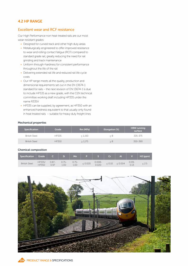
4.2 HP RANGE
Excellent wear and RCF resistance
Our High Performance non heat-treated rails are our most
wear-resistant grades:
• Designed for curved track and other high duty areas
• Metallurgically engineered to offer improved resistance
to wear and rolling contact fatigue (RCF) compared to
standard grade rail, greatly reducing the need for rail
grinding and track maintenance
• Uniform through-hardness for consistent performance
throughout the life of the rail
• Delivering extended rail life and reduced rail life cycle
costs
• Our HP range meets all the quality, production and
dimensional requirements set out in the EN 13674-1
standard for rails – the next revision of EN 13674-1 is due
to include HP335 as a new grade, with the CEN technical
committee working draft including HP335 under the
name R335V
• HP335 can be supplied, by agreement, as HP350 with an
enhanced hardness equivalent to that usually only found
in heat treated rails – suitable for heavy duty freight lines
Mechanical properties
Chemical composition
Specification Grade Rm (MPa) Elongation (%)HBW running
surface
British Steel HP335 ≥ 1,150 ≥ 8 335-375
British Steel HP350 ≥ 1,175 ≥ 8 350-390
Specification Grade C Si Mn P S Cr Al V H2 (ppm)
British SteelHP335/HP350
0.87-0.97
0.75-1.00
0.75-1.00
≤ 0.0200.008-0.020
≤ 0.10 ≤ 0.0040.09-0.13
≤ 2.5
PRODUCT RANGE & SPECIFICATIONS104

4.3 ZINOCO®

4.3 ZINOCO®
Unbeatable corrosion protection
Our Zinoco® coated rail offers superior protection against
corrosion for longer rail life.
Ideal for corrosive conditions e.g. tunnels, level crossings, salt
pans and areas of stray current.
Developed in partnership with UK customer Network Rail
who required a durable coating to withstand corrosion.
Zinoco offers 2 lines of defence:
• Durable barrier to combat corrosion
• Provides sacrificial protection, so still works if the coating
is damaged
Zinoco coated rail protects against corrosion in the orange
areas highlighted in the diagram below, enabling the rail to
resist pitting, gall and general loss of section due to corrosion.
Currently being used by Network Rail (UK) and RATP (France),
and approved for use by Irish Rail (Ireland) and London
Underground (UK).
Performance against current competition
CoatingSacrificial protection
Stray current protection
Abrasion resistance
Impact resistance
Coating removal (for welding)
Zinoco® Yes Excellent Excellent Good Moderate
Railcote® Yes Excellent Moderate Moderate Easy
Aluminium metal spray No Poor Very good Good Difficult/hazardous
Glass flake epoxy No Poor once damaged Very poor Very poor Difficult/hazardous
Glass flake polyester No Poor once damaged Poor Poor Difficult/hazardous
PRODUCT RANGE & SPECIFICATIONS106

4.4 STEEL SLEEPERS

4.4 STEEL SLEEPERS
Steel sleeper dimensions
Sleeper profile
Plateweight kg/m
Section height mm (A)
Section width
mm (B)
Rail seat width
mm (C)
Rail seat thicknessmm (D)
Leg thickness
mm (E)
Moment of inertia lxx cm4
Section modulus
cm3
Height of neutral axis from base
mm (F)
202 22.10 82 240 160 7.5/12.0 6.75 200.0 34.4 58.1
300 28.36 92 254 160 12.0 7.0 283.3 42.3 67.0
402 28.54 100 260 168 10.0 7.0 426.0 62.8 67.1
436 31.69 100 260 168 12.0 7.0 432.8 65.8 68.4
600 39.53 115 280 168 14.5 7.6 654.7 81.3 80.5
Notes: Can be supplied for all rail sizes and with the inclination required for your network. Can be tailored to any rail gauge – 1,000mm, 1,067mm (3’ 6”), standard and broadgauge.
Chemical composition % by mass Mechanical properties
Specification Grade C Si Mn P S Cr Al V H2 (ppm)Rm
(MPa)Elongation
(%)
EN 10025 S275 ≤ 0.210.14-0.25
≤ 1.50 ≤ 0.035 ≤ 0.035 – ≤ 0.008 – –410-560
≥ 23
Steel sleeper grade
Lower lifetime costs with efficient logistics
Our steel sleepers are designed for use in all types of
application, from metre gauge railways to mainline passenger
and heavy haul routes.
They require less ballast than traditional concrete sleepers,
leading to reduced track construction and renewal costs.
Once installed, steel sleepers don’t rot or suffer from insect
attacks. They also survive well in wet tropical climates where
wood decays rapidly.
Being fully recyclable, our steel sleepers also benefit from
a smaller carbon footprint, making it easier to hit your
sustainability targets.
Steel sleepers are stackable and because they are lighter
than concrete sleepers, can be moved in bundles by a
forklift (or manually handled if regulations allow).
Often requiring only a third of the vehicle movements
needed by concrete sleepers, using our steel sleepers helps
to keep transportation costs to a minimum.
Our steel sleepers can be delivered with all fastening
systems pre-installed, helping to keep your installation times
to a minimum.
PRODUCT RANGE & SPECIFICATIONS108

5 SEMI-FINISHED PRODUCTS

ABOUT SEMI-FINISHED PRODUCTSOur integrated steelmaking site at Scunthorpe produces
a variety of semi-finished products to suit our customers’
rolling requirements for long, structural or general
engineering products.
Our steel is produced through the basic oxygen steelmaking
(BOS) process, and can then be refined as appropriate in a
ladle arc furnace and vacuum degasser facilities.
These processes control the steel temperatures and
chemistries extremely tightly, ensuring our wide range
of steel grades meet the most demanding customer
requirements.
Our slabs, blooms and billets are continuously cast in
sequences and the steel is fully shrouded between the ladle
and the tundish and for slabs and blooms, between tundish
and mould. Hood cooling may also be used for slabs and
blooms to remove hydrogen, depending on the hydrogen
content and specification required. On completion, our
billets are identified to cast level, while blooms and slabs are
uniquely-identified to ensure traceability.
British Steel is accredited to both ISO 9001:2015 for our
quality management system and ISO 14001:2015 for our
environmental management system. Our steelmaking and
casting processes also hold ABS, BV, CCS, DNV, LRS and
RINA shipbuilding accreditations.
In addition to verifying the chemical composition and
segregation of our steel, we have well-equipped laboratories
onsite where other tests can be conducted as required.
PRODUCT RANGE & SPECIFICATIONS110

5.1 SLABS

5.1 SLABS
Our steel slabs are suitable for rolling to reversing mill plate,
hot rolled coil and structural sections for a range of structural
and general engineering applications.
Dimensions Measurement
Length min 6,900mm
Length max 10,500mm
Piece weight max 34.5t
Dimensions
Thickness
Width
mm 225 298
in 9 12
800 31 1/2
1,095 43 1/8
1,270 50
1,425 56 1/8
1,525 60
1,540 60 5/8
1,605 63 3/16
1,820 72 2/3
1,970 77 9/16
Documentation
Inspection certificates will be supplied for products being
rolled in accordance with EN 10204, with the following
elements being routinely analysed at cast level:
Element No. of reported digits after decimal point
C, Si, Mn 2
P, S, Al(t), V, Ti, Nb, Sn, Mo, Co, Ca, Cu, Ni, Cr, N2
3
B 4
Bespoke slabs for your rolling needs
Our slabs can be tailored to best meet the attributes of your
products and help you meet the appropriate national and
international standards. Please contact us to discuss your
requirements.
Application Standard
Structural steel Suitable for rolling to EN 10025 e.g. S235, S275, S355
Structural steel Suitable for rolling to ASTM e.g. A36, A992, A572 gr 50
Low carbon hot rolled coil Suitable for rolling to EN 10111
PRODUCT RANGE & SPECIFICATIONS112

5.1 SLABS
Tolerances
Tolerance Measurement (all section sizes)
Thickness + / - 5mm
Width+ / - 20mm
(last in sequence + 20mm / - 45mm)
Length* + / - 100mm
Notes: *Shorts allowance up to 3 pieces per strand per sequence.
Thickness varianceT₁ - (T₂ + T₃) / 2 ≤ 5mm
T₃ T₂T₁ Thickness varianceH₁ - H₂ ≤ 5mm
H₁H₂
W₁
W₂
TaperW₁ - W₂ ≤ 15mm
SquarenessL₁ - L₂ ≤ 25mm
L₁L₂
Tz
Trapezoid ≤ 10mm (each side)Tz
Edge bulgeE ≤ 10mm
EB
B
Edge concavityE ≤ 10mm
EC
C
Step cutsd ≤ 10mm
d
Cross bow / concavity ≤ 5mm/mCb
Cb
Bow flatness ≤ 5mm/mBf
Bf
Camber ≤ 5mm/mCr
Cr
Quantity
Nominal order in 280 metric tonne multiples. Overall order quantity + / - 10%.
113PRODUCT RANGE & SPECIFICATIONS
5.2 BLOOMS

5.2 BLOOMS
Blooms are supplied in ‘as-cast’ condition with normal levels
of scale. Superficial surface corrosion may occur during
storage and shipping. The external surface will be free from
longitudinal and transverse cracks, slivers, corrugation, gas
cavities and slag inclusions.
Blooms are flame-cut to length.
Internal quality
Blooms will be free from excessive segregation, pipe, internal
laminations, slag inclusions and blowholes.
Surface quality
Our steel blooms have a rectangular cross-section and are
suitable for structural, rail and wire rod applications.
Tolerances
Size
Dimensions Measurement (mm)
Length min 4,000
Length max 9,600
Tolerance Measurement (all section sizes)
Thickness + / - 8mm
Width + / - 8mm
Length* + / - 120mm
Notes: *Shorts allowance up to 5% of blooms down to customers' minimum length.
Tolerance Measurement (all section sizes)
Bloom straightness 0.5% of length
Rhomboidity 10mm of nominal length diagonal
Twist 1° max per metre with max 4° per length
Concavity / convexity
+ / - 1.5% of thickness and width max
Cut straightness 3% of length of cut
Notes: These features are not measured on a regular basis but standard caster output is within the above tolerances. Incidents which lead to a deterioration in quality of caster output would prompt investigation into suitability of cast product for intended orders.
Shape
Notes: Individual bloom weights are calculated from the declared dimensions.
Dimensions
Thickness (mm)
Width (mm)
231 254 309
283
330
360
486
115PRODUCT RANGE & SPECIFICATIONS

5.2 BLOOMS
Bloom ends
Blooms will be supplied 'as-cut' with flame cut ends.
20mm
10mm
Longitudinal directionCutting fin mm
Width ≤ 20mm
Thickness ≤ 10mm
Quantity
Nominal order in 280 metric tonne multiples. Overall order
quantity + / - 10%.
Documentation
Inspection certificates will be supplied for products being
rolled in accordance with EN 10204, with the following
elements being routinely analysed at cast level:
Element No. of reported digits after decimal point
C, Si, Mn 2
P, S, Al(t), V, Ti, Nb, Sn, Mo, Co, Ca, Cu, Ni, Cr, N2
3
B 4
Bespoke blooms for your rolling needs
Our blooms can be tailored to best meet the attributes of
your products and help you meet the appropriate national
and international standards. Please contact us to discuss your
requirements.
Application Standard
Structural steel Suitable for rolling to EN 10025 e.g. S235, S275, S355
Structural steel Suitable for rolling to ASTM e.g. A36, A992, A572 gr 50
PRODUCT RANGE & SPECIFICATIONS116

5.3 BILLETS

5.3 BILLETS
Our steel billets have a square cross-section and are suitable
for steel-reinforcement, structural, low-carbon and drawing
applications.
Dimensions
Dimension Measurement (mm)
Width and thickness 140 x 140
Width and thickness 180 x 180
Tolerances
Section overall
Measure section mid-face S1 and S2 (preferred method)
Dimension Measurement (mm)
Length min 8,000
Length max 14,000
Section mm
140mm - 3 / + 5
180mm -2 / + 6
Rhomboidity
Measure diagonal D1 and D2
Diagonal difference D1 - D2
Section Measurement
140mm 10mm max
180mm 14mm max
All 3° max
l
S2
S1D2D1
c
l
Tolerance Measurement (all section sizes)
Length* + / - 100mm
Straightness** 10mm/m or 100mm max on overall length
Notes: *Shorts allowance up to 5% of billets down to customers' minimum length.**Measure gap from flat surface or wire stretched end-to-end.
PRODUCT RANGE & SPECIFICATIONS118

5.3 BILLETS
Documentation
Inspection certificates will be supplied for products being
rolled in accordance with EN 10204, with the following
elements being routinely analysed at cast level:
Element No. of reported digits after decimal point
C, Si, Mn 2
P, S, Al(t), V, Ti, Nb, Sn, Mo, Co, Ca, Cu, Ni, Cr, N2
3
B 4
Bespoke billets for your rolling needs
Our billets can be tailored to best meet the attributes of your
products and help you meet the appropriate national and
international standards. Please contact us to discuss your
requirements.
Application Standard
Structural steel Suitable for rolling to EN 10025 e.g. S235, S275, S355
Structural steel Suitable for rolling to ASTM e.g. A36, A992, A572 gr 50
Plain and deformed reinforcement bar Various
Low carbon wire rod Various
Tolerance Measurement (all section sizes)
Twist 3° max on overall length
Fash / flame cutting burr
x = 10mm max
Corner radius r = 4mm
QuantityNominal order in 280 metric tonne multiples
Overall order quantity + / - 10%
lα
xr
119PRODUCT RANGE & SPECIFICATIONS

6 CONTACTS

6 CONTACTS
Scunthorpe
Brigg Road, Scunthorpe, North Lincolnshire, DN16 1BPT +44 (0) 1724 404040
Product areas email contacts
Dublin
Steel House, Bluebell Industrial Estate, Dublin 12T +353 (0) 1405 0300E [email protected]
Skinningrove
PO Box 1, Skinningrove, Saltburn-by-the-Sea, TS13 4ETT +44 (0) 1287 640212E [email protected]
Ireland Service Centre – Lisburn
Steel House, Moira Road, Lisburn, BT28 2SNT +44 (0) 2892 448208E [email protected]
Newport
Excalibur House, No 1 Langstone Business Park,Newport, NP18 2HJT +44 (0) 1633 462653 / +44(0)1633 462636E [email protected]
Workington
TSP Engineering, Derwent Howe Industrial Estate, Curwen Road, Workington CA14 3YXT +44 (0) 1900 68000E [email protected]
Teesside Service Centre
Lackenby Works, Redcar, Teesside, TS6 7RPT +44 (0) 1642 405040E [email protected]
If you want to find out more about our product range and how we can help you, please get in touch.
The contact details listed here are correct at the time of publication. For the latest details of your nearest location, please visit britishsteel.co.uk/locations.
Semi-finished products: [email protected]: [email protected] Profiles: [email protected] Rod: [email protected] and processing: [email protected]: [email protected]
By product
By UK location
SCUNTHORPE
SKINNINGROVELISBURN
DUBLIN
WORKINGTON
NEWPORT
ALBLASSERDAM
SHEFFIELD
TEESSIDE
DARLINGTON
121PRODUCT RANGE & SPECIFICATIONS

Poland
Ul. Chorzowska 150, budynek B, 40-101 KatowiceT +48 32 7841232E [email protected]
Taiwan
Room 829, 5th Floor, No. 285, Section 4, Zhongxiao East Road, Taipei City, 10692T +886 (0) 266398296E [email protected]
Spain
Paseo de la Castellana 259C, Torre de Cristal, Planta 18, Oficina 1811. 28046, MadridT +34 91 119 0581E [email protected]
Germany
Hansaallée 228 / Ecke Prinzenallée, 40547 DüsseldorfT +49 (0)211 740 714-00E [email protected]
Turkey
DLT Celik Ithalat Ihracat ve Pazarlama A.S., Arnavutkoy Mah. Girgin Sok. No:1, 34345 Besiktas, IstanbulT +90 (212) 287 8617E [email protected]
Italy
Via Italia 44, 20900 Monza (MB)T +39 039 387967E [email protected]
By country
USA
1700 East Golf road suite 575, Schaumburg, IL 60173T +1 708 8190698E [email protected]
Sweden
Box 5044, Spinnerivägen 1, 448 51, TolleredE [email protected]
PRODUCT RANGE & SPECIFICATIONS122

NOTES
123PRODUCT RANGE & SPECIFICATIONS

PR:ENG:052020
BRITISHSTEEL.CO.UKPO Box 1, Brigg Road, Scunthorpe, North Lincolnshire, DN16 1BP, United Kingdom+44 (0)1724 404040
AT
| |
Care has been taken to ensure that the contents of this publication are accurate, but British Steel Limited and its subsidiaries and associated undertakings (having the meaning set out in the Companies Act 2006) do not accept responsibility or liability for errors or information that is found to be misleading.
Copyright British Steel 2020
British Steel Limited is registered in England under number 12303256 with registered office at Administration Building, Brigg Road, Scunthorpe, DN16 1XA.