Embed Size (px)
Citation preview

- 1 -
Product name: Video Server (VS2402) Release Date: 2005/10/28 Manual Revision: 2.00
Web site: www.vivotek.com Email: [email protected]
Made in Taiwan. ©Copyright 2000-2005. All rights reserved
- 2 -
Before You Use
It is important to carefully examine the contents with the Chapter Package Contents
after opening the package. If there is anything missing, contact your reseller. Read the
Chapter Physical Description before assembling and operating the device and
peripherals. Understanding the physical description can prevent damage caused by
abnormal usage and reduce most problems during installation.
Basically Video Server is a network device and should be easy to use for those who
already have basic network knowledge. If there is a system error and it does not recover
easily due to erroneous configuration, read the System recovery section in Appendix
Troubleshooting to restore factory default settings and perform installation again.
Video Server has been designed for various environments and can be used to build
various applications for general security or demonstration purposes. For standard
applications, find the appropriate section in the Chapter How to Use for your application
and follow the steps to setup the system. To make best use of Video Server, read Chapter
Advanced Functions to get creative ideas and review Chapter System Configuration for
detailed explanations of system configurations. To those professional developers, the
Appendix URL Commands of Video Server will be a very helpful reference to develop a
Web-based application.
Surveillance devices may be prohibited by law in your country. Though Video Server is
not only a high performance surveillance system but also a networked video server,
ensure that the operations of such devices are legal before installing this unit for
surveillance.
Those paragraphs preceding with must be fully understood and cautioned.
Ignoring the warnings may result in serious hazards.
- 3 -
Table of Contents
Before You Use.......................................................2
Package Contents...................................................5
Features and Benefits.............................................1
Physical Description ...............................................6
Front Panel ......................................................................6 Rear Panel .......................................................................8
Installation...........................................................11
Ethernet Environment......................................................12 Initial Access to the Video Server ......................................13 Modem Environment .......................................................14
How to Use...........................................................23
Authentication ................................................................23 Installing Plug-in.............................................................24 Main Page......................................................................25
System Configuration ...........................................28
Introduction ...................................................................28 Setup Wizard ..............................................................29
Application Wizard.......................................................29
Definitions of Configuration ..............................................30
Advanced Functions .............................................44
Capture Up-to-date Still Images........................................44 Get Continuous Images ...................................................45 Video Embedded in Customers’ Homepage .........................46 Download Event-triggered Snapshots.................................47 Uploading Snapshots Periodically ......................................48 Customize Graphics in Homepage .....................................49 Command Script for Complex Applications..........................50
- 4 -
URL for External Device Control ........................................53 URL of System Maintenance .............................................55 Configure System via FTP ................................................56 Telnet Commands ...........................................................64
Appendix ..............................................................66
A. Troubleshooting ..........................................................66 B. Frequently Asked Questions..........................................68 C. Upgrade System Firmware ...........................................72 D. URL Commands of Video Server....................................73 E. Settings of Supported PTZ Cameras...............................88 F. Camera Control Cable...................................................89 G. Time Zone Table .........................................................90 H. Technical Specifications ...............................................93
- 5 -
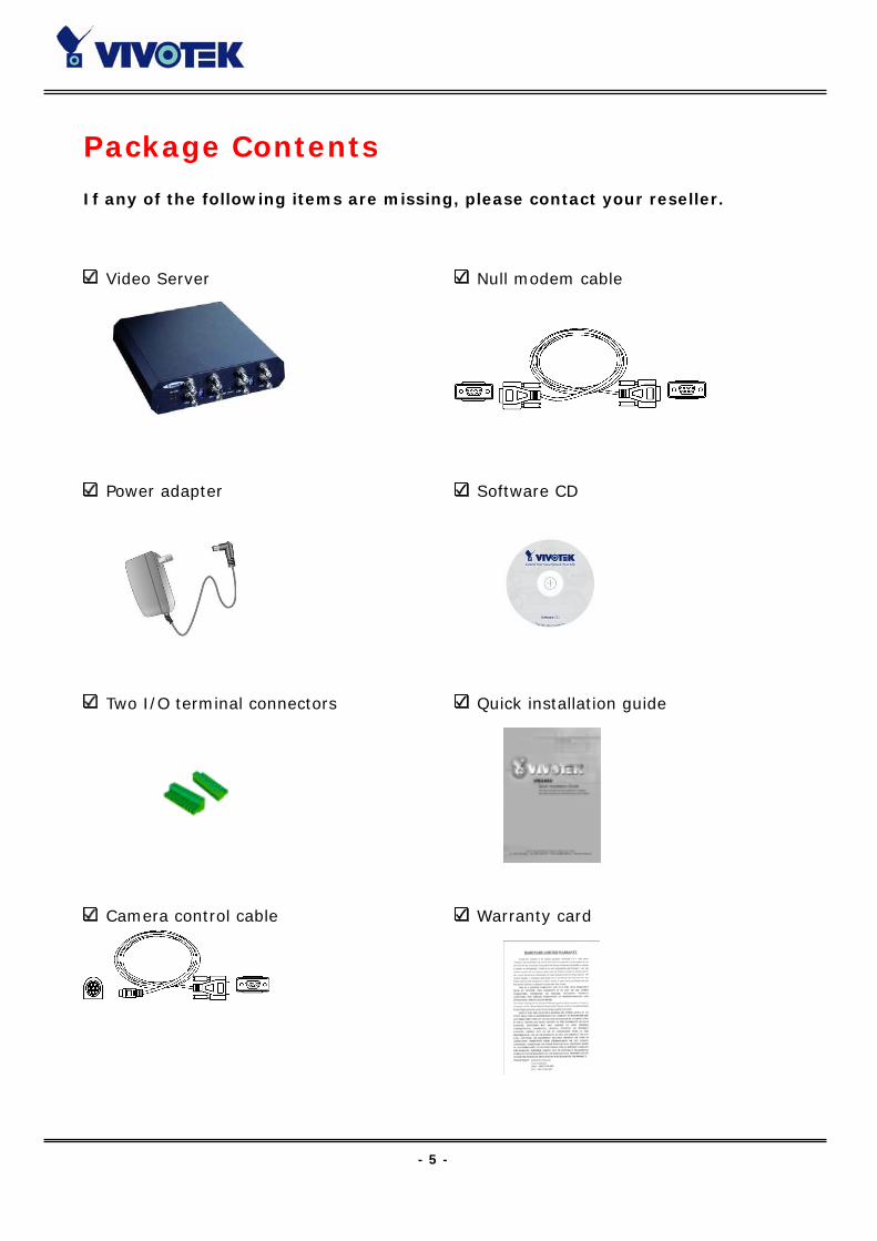
Package Contents
If any of the following items are missing, please contact your reseller.
Video Server
Power adapter
Two I/O terminal connectors
Camera control cable
Null modem cable
Software CD
Quick installation guide
Warranty card

- 1 -
Features and Benefits
Video Server is a high-performance networking video multiplexer. With powerful VLIW
DSP core and fully optimized algorithm, it can compress and transmit the high quality
real-time video through standard TCP/IP inter-network. In addition to meet the basic
needs of video feed, many advanced features are added to help building applications of
surveillance or web attraction. The state-of-art design well compromises among stable,
robust, simple-to-use and flexibility.
☆ Real-time motion-JPEG compression
Four video inputs can be efficiently compressed into packets of JPEG images without
delay. Optimal compression engine makes the equivalently excellent image with much
smaller size. There is no more sacrifice in remote monitoring and storage. Five levels of
compression ratio and three sizes of image resolutions are easy to meet your
requirement.
☆ Robust system operation
Industrial real-time operating system prevents from malicious hackers and virus that
threat Windows or Linux systems. The on-board watchdog eternally monitors the system
operations for dead-proof.
☆ Easy Web access via standard browser
You don’t have to install any software to access Video Server. The embedded Web server
makes users can access Video Server anywhere over Internet with any popular Web
browser. As long as you are connected to network, you can cast your eyes on your
precious property.
☆ Password protection of system access
Password level protection is provided by the system to prevent from malicious intruders
from network. Once the password of administrator is entered, any user will need
password authentication to access Video Server. Each user can have individual access
right to view video or control external devices.
☆ Built-in motion detection
No more external sensors are required. Each video channel can be setup to detect any
motion with customized settings. By tuning the object size and sensitivity, it is more
- 5 -
reliable to fit into your environment. With this built-in facility, you can easily setup a
security system in your home or office.
☆ Weekly schedule for automatic surveillance
The user-defined time period will repeat weekly to check any security settings and
accordingly sending notification or drive external devices. It is easy to install in SOHO,
retail shop and home as a security system.
☆ Flexible I/O control for external devices
There are four opto-isolated sensor inputs and two relay outputs to control external
devices. System integrators can easily replace the current analog systems to build an
advanced security system.
☆ Bundled powerful surveillance software
To extend the capabilities of Video Server, a powerful surveillance program is included in
the package and totally free to use. Users can easily utilize the existing PC to be a digital
video recorder. Schedule or one-click recording keep every important moment in your
local hard disk; reliable motion detection and instant warning make you sharp for every
conditions. Quick and simple search and playback let you easily find the moment you
want to inspect more carefully and output to AVI files for another copy.
☆ Remote system upgrade
To achieve the promise we made to support our valuable customers in life-time, the most
up-to-date firmware is always put on our web site to add new functions or solve known
bugs. A free upgrade wizard is included to facilitate the job.
☆ Developer’s technical support
The high-performance Video Server can be integrated into many applications under
perfect control of budget. The complete programming interface and standard JPEG
format can ease and speed developers’ task. More creative ideas can be found on our
Web site.
- 6 -
Physical Description
Front Panel
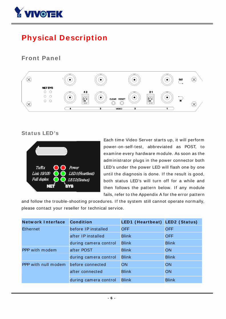
Status LED’s Each time Video Server starts up, it will perform
power-on-self-test, abbreviated as POST, to
examine every hardware module. As soon as the
administrator plugs in the power connector both
LED’s under the power LED will flash one by one
until the diagnosis is done. If the result is good,
both status LED’s will turn off for a while and
then follows the pattern below. If any module
fails, refer to the Appendix A for the error pattern
and follow the trouble-shooting procedures. If the system still cannot operate normally,
please contact your reseller for technical service.
Network Interface Condition LED1 (Heartbeat) LED2 (Status)
before IP installed OFF OFF
after IP installed Blink OFF
Ethernet
during camera control Blink Blink
after POST Blink ON PPP with modem
during camera control Blink Blink
before connected ON ON
after connected Blink ON
PPP with null modem
during camera control Blink Blink
- 7 -
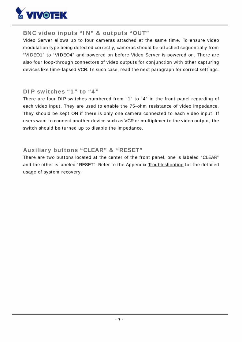
BNC video inputs “IN” & outputs “OUT” Video Server allows up to four cameras attached at the same time. To ensure video
modulation type being detected correctly, cameras should be attached sequentially from
“VIDEO1” to “VIDEO4” and powered on before Video Server is powered on. There are
also four loop-through connectors of video outputs for conjunction with other capturing
devices like time-lapsed VCR. In such case, read the next paragraph for correct settings.
DIP switches “1” to “4” There are four DIP switches numbered from “1” to “4” in the front panel regarding of
each video input. They are used to enable the 75-ohm resistance of video impedance.
They should be kept ON if there is only one camera connected to each video input. If
users want to connect another device such as VCR or multiplexer to the video output, the
switch should be turned up to disable the impedance.
Auxiliary buttons “CLEAR” & “RESET” There are two buttons located at the center of the front panel, one is labeled “CLEAR”
and the other is labeled “RESET”. Refer to the Appendix Troubleshooting for the detailed
usage of system recovery.
- 8 -
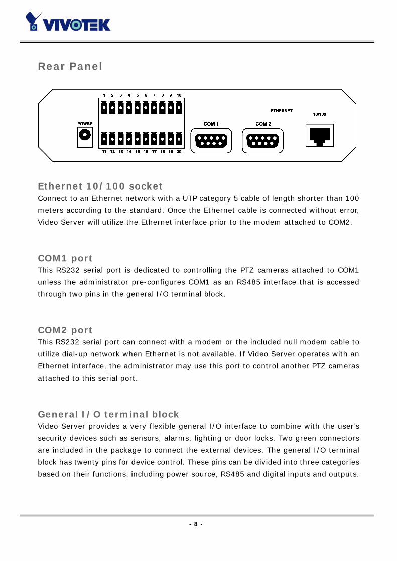
Rear Panel
Ethernet 10/100 socket Connect to an Ethernet network with a UTP category 5 cable of length shorter than 100
meters according to the standard. Once the Ethernet cable is connected without error,
Video Server will utilize the Ethernet interface prior to the modem attached to COM2.
COM1 port This RS232 serial port is dedicated to controlling the PTZ cameras attached to COM1
unless the administrator pre-configures COM1 as an RS485 interface that is accessed
through two pins in the general I/O terminal block.
COM2 port This RS232 serial port can connect with a modem or the included null modem cable to
utilize dial-up network when Ethernet is not available. If Video Server operates with an
Ethernet interface, the administrator may use this port to control another PTZ cameras
attached to this serial port.
General I/O terminal block Video Server provides a very flexible general I/O interface to combine with the user’s
security devices such as sensors, alarms, lighting or door locks. Two green connectors
are included in the package to connect the external devices. The general I/O terminal
block has twenty pins for device control. These pins can be divided into three categories
based on their functions, including power source, RS485 and digital inputs and outputs.
- 9 -
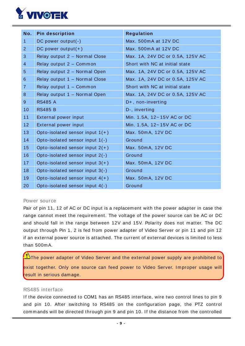
No. Pin description Regulation
1 DC power output(-) Max. 500mA at 12V DC
2 DC power output(+) Max. 500mA at 12V DC
3 Relay output 2 – Normal Close Max. 1A, 24V DC or 0.5A, 125V AC
4 Relay output 2 – Common Short with NC at initial state
5 Relay output 2 – Normal Open Max. 1A, 24V DC or 0.5A, 125V AC
6 Relay output 1 – Normal Close Max. 1A, 24V DC or 0.5A, 125V AC
7 Relay output 1 – Common Short with NC at initial state
8 Relay output 1 – Normal Open Max. 1A, 24V DC or 0.5A, 125V AC
9 RS485 A D+, non-inverting
10 RS485 B D-, inverting
11 External power input Min. 1.5A, 12~15V AC or DC
12 External power input Min. 1.5A, 12~15V AC or DC
13 Opto-isolated sensor input 1(+) Max. 50mA, 12V DC
14 Opto-isolated sensor input 1(-) Ground
15 Opto-isolated sensor input 2(+) Max. 50mA, 12V DC
16 Opto-isolated sensor input 2(-) Ground
17 Opto-isolated sensor input 3(+) Max. 50mA, 12V DC
18 Opto-isolated sensor input 3(-) Ground
19 Opto-isolated sensor input 4(+) Max. 50mA, 12V DC
20 Opto-isolated sensor input 4(-) Ground
Power source Pair of pin 11, 12 of AC or DC input is a replacement with the power adapter in case the
range cannot meet the requirement. The voltage of the power source can be AC or DC
and should fall in the range between 12V and 15V. Polarity does not matter. The DC
output through Pin 1, 2 is fed from power adapter of Video Server or pin 11 and pin 12
if an external power source is attached. The current of external devices is limited to less
than 500mA.
The power adapter of Video Server and the external power supply are prohibited to
exist together. Only one source can feed power to Video Server. Improper usage will
result in serious damage.
RS485 interface If the device connected to COM1 has an RS485 interface, wire two control lines to pin 9
and pin 10. After switching to RS485 on the configuration page, the PTZ control
commands will be directed through pin 9 and pin 10. If the distance from the controlled
- 10 -
device is too far to allow accurate function, an external power source may be used to
amplify the RS485 signal.
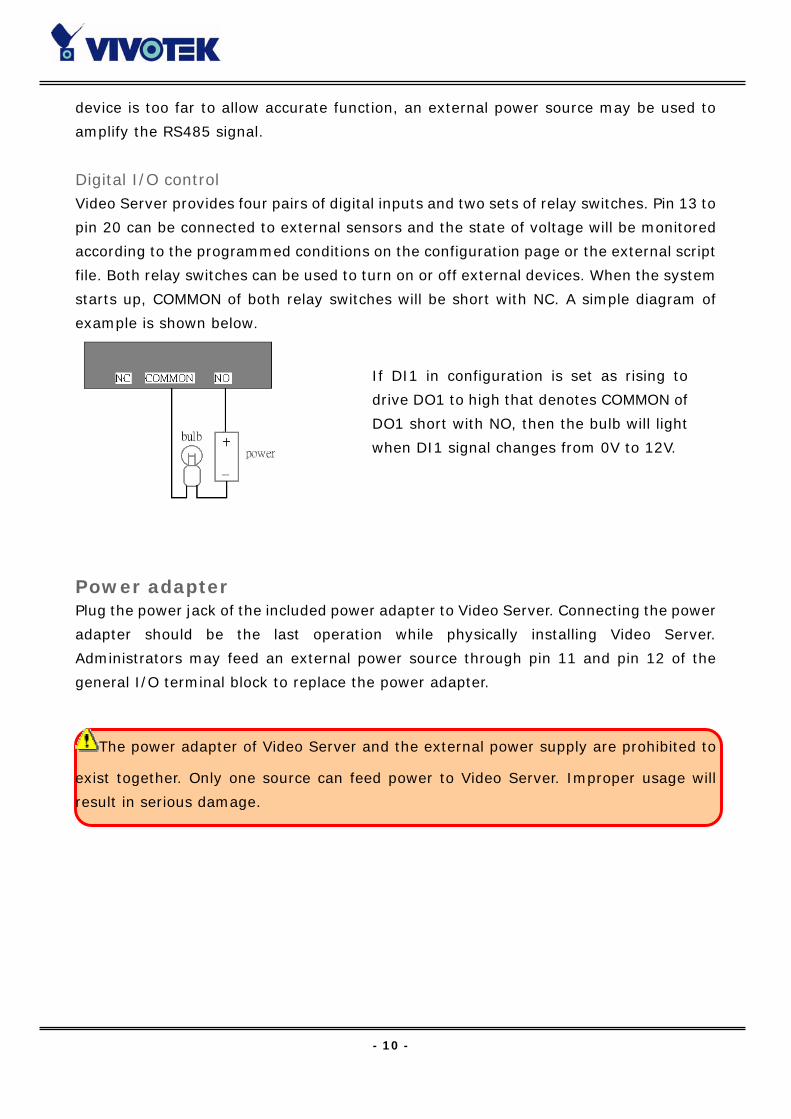
Digital I/O control Video Server provides four pairs of digital inputs and two sets of relay switches. Pin 13 to
pin 20 can be connected to external sensors and the state of voltage will be monitored
according to the programmed conditions on the configuration page or the external script
file. Both relay switches can be used to turn on or off external devices. When the system
starts up, COMMON of both relay switches will be short with NC. A simple diagram of
example is shown below.
Power adapter Plug the power jack of the included power adapter to Video Server. Connecting the power
adapter should be the last operation while physically installing Video Server.
Administrators may feed an external power source through pin 11 and pin 12 of the
general I/O terminal block to replace the power adapter.
The power adapter of Video Server and the external power supply are prohibited to
exist together. Only one source can feed power to Video Server. Improper usage will
result in serious damage.
If DI1 in configuration is set as rising to
drive DO1 to high that denotes COMMON of
DO1 short with NO, then the bulb will light
when DI1 signal changes from 0V to 12V.

- 11 -
Installation
To easily fit into various environments, the Video Server automatically detects the
attached interfaces and configures itself to the best condition. Therefore users need not
care whether the connected cameras are either NTSC or PAL, how to select the network
between Ethernet and modem, and whether the Ethernet speed is 10Mbps or 100 Mbps.
If the connected motorized camera is on the support list, users only need to plug and
play without complicated configurations.
The Video Server supports Ethernet and modem interfaces according to the user's
existing network. Ethernet can provide higher bandwidth to achieve the best
performance while dial-up network with modem is more common in current Internet
applications. Refer to the related installation section for your network environment. If
both interfaces are available, Ethernet is recommended and will be chosen as the first
priority if Ethernet cable and modem are concurrently attached. Managing to install in
the other interface will automatically clear the previous network settings to start new
installation.
In the following content, "user" refers to those who can access the Video Server and
"Administrator" refers to the supervisor who has the root password to configure the
Video Server in addition to general access. Administrator should carefully read this
manual, especially during installation.
- 12 -
Ethernet Environment
Hardware installation Before installing multiple Video Server’s at the well-chosen locations, the administrator
should memorize the serial numbers on the packages respectively for future use.
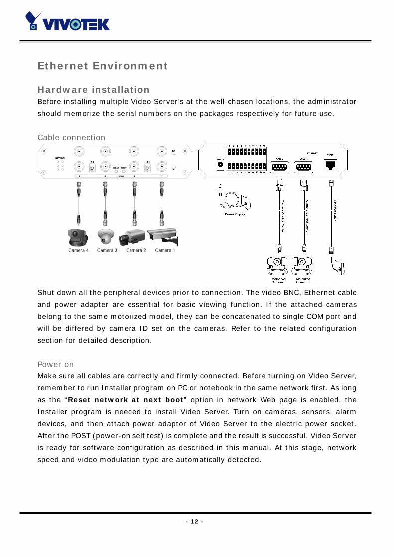
Cable connection
Shut down all the peripheral devices prior to connection. The video BNC, Ethernet cable
and power adapter are essential for basic viewing function. If the attached cameras
belong to the same motorized model, they can be concatenated to single COM port and
will be differed by camera ID set on the cameras. Refer to the related configuration
section for detailed description.
Power on Make sure all cables are correctly and firmly connected. Before turning on Video Server,
remember to run Installer program on PC or notebook in the same network first. As long
as the “Reset network at next boot” option in network Web page is enabled, the
Installer program is needed to install Video Server. Turn on cameras, sensors, alarm
devices, and then attach power adaptor of Video Server to the electric power socket.
After the POST (power-on self test) is complete and the result is successful, Video Server
is ready for software configuration as described in this manual. At this stage, network
speed and video modulation type are automatically detected.
- 13 -
Initial Access to the Video Server
The Video Server can be connected either before or immediately after software
installation onto the Local Area Network. The Administrator should complete the network
settings on the configuration page. For complete protection from illegal usage, the Video
Server provides two privileges and always needs user name and password before access.
The standard level is the USER mode that consists of twenty user profiles. Each user is
able to access the Video Server except for system configuration. Twenty users’ profiles
are also maintained by the administrator. The highest level is ROOT mode that only
opens to Administrator for initial setup, system configuration, user administration and
software upgrade. The user name of the Administrator is internally assigned to “root”.
When connecting to the Video Server, users will be requested for user name and
password by an authentication message window. A root password, identical to the Video
Server's serial number, is needed for the initial access to a newly installed Video Server.
The administrator must change the root password immediately after the initial
installation to ensure security. The new root password should be well memorized since
there is no way to retrieve or recover it. After changing the password, the browser will
display an authentication window again to ask for the new password.
The other important part is network settings. The software configuration above makes
the Video Server easily accessed through local networks. However Administrator should
review the network settings on the configuration page according to the existing service.
The safe and easy way is to compare the network settings with another PC or
workstation in the same network.
By default the Video Server will acquiring IP address automatically every time it reboots.
If the network settings are sure to work all the time, disable the “Reset network at
next boot” option if this IP address is already reserved for this the Video Server.
Clearing this option will fix IP address of the video server every time it boots up. If the
option stays checked, the Video Server will pick up any available IP address
automatically every time the system boots up.
- 14 -
Modem Environment
Hardware installation Though Video Server is designed to serve real-time images in Ethernet, it also supports
the dial-up network. To use a dial-up network, the Ethernet socket should be left
disconnected since Ethernet is the first priority among available interfaces. After
powering up, Video Server will detect if any external modem is connected to COM2. As
soon as a modem is detected, the heartbeat LED will flash periodically. If no modem
responds, Video Server will assume the included null modem cable is connected to
perform system configuration. Then both LED’s under the power LED will turn on until
the dial-up connection over null modem is established.
Installations of both null modem and modem are introduced as follows. The null modem
mode can be used for point-to-point connection in local environment; the modem mode
also applies to TA in ISDN network. Though the baud rate can be setup to 115200 bit per
second, the actual data rate depends on the network connection.
In the following content, dial-in connection denotes a passive Video Server waiting for a
phone call to establish a point-to-point connection. Dial-out connection denotes an
active Video Server to dial out to the other end of a dial-up server or any Internet service
provider, abbreviated as ISP, to request a point-to-point connection.
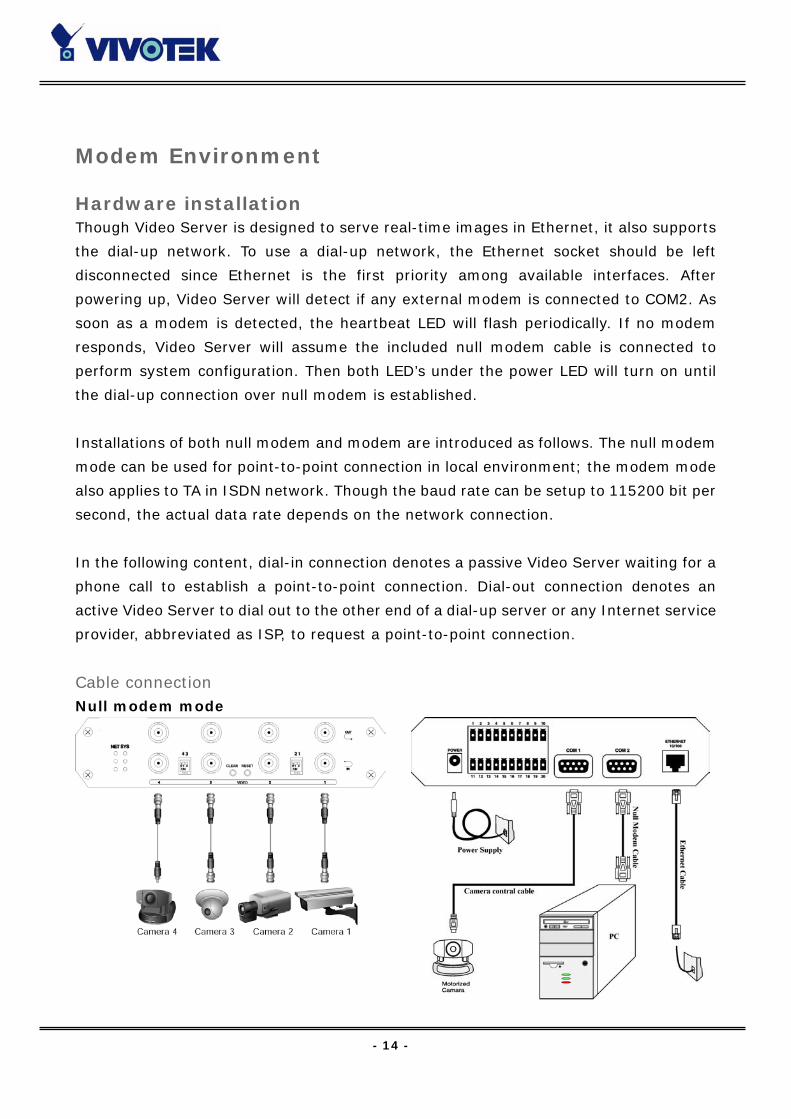
Cable connection Null modem mode

- 15 -
Shut down the peripheral devices prior to connection and keep the power adaptor
unplugged until other cables are firmly connected. In the environment without Ethernet,
administrators can use the included null modem cable to connect to Video Server directly
and access point-to-point. After necessary information is entered and saved, turn off
Video Server and remove the null modem cable. Follow the installation of modem mode
in next paragraph to connect to Internet. Note Video Server will not really reset system
where it is used to in null modem mode.
Modem mode
If users have setup a remote dialup server or subscribed to an ISP service, Video Server
can be configured to dial to the server upon user-defined events. Otherwise it will wait
permanently for the user’s call to establish a network connection to provide services.
Before installation, make sure the necessary dialing information is correctly setup via
Ethernet or null modem connection.
Power on Make sure all cables are correctly and firmly connected. Turn on cameras, sensors, alarm
devices, and then finally attach the power adaptor of Video Server to the electric power
outlet. Since most automatic detections of hardware perform when the system starts,
Video Server should be turned on after all peripherals are turned on and ready.
- 16 -
Software installation Via Ethernet Enter the COM2 configuration Web page and select the driver type as modem. Well
configure each field for dialing information. Refer to the COM2 section in Definition of
Configuration for detailed description.
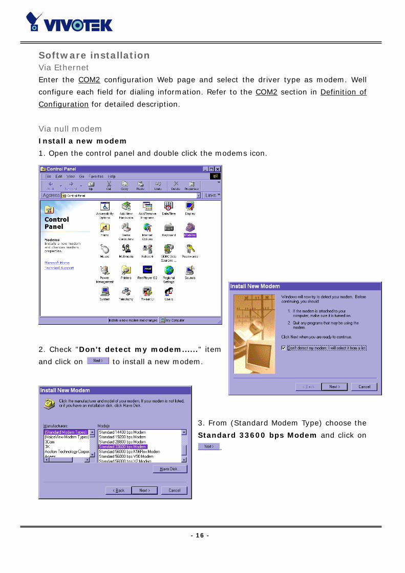
Via null modem Install a new modem
1. Open the control panel and double click the modems icon.
2. Check "Don't detect my modem......" item
and click on to install a new modem.
3. From (Standard Modem Type) choose the
Standard 33600 bps Modem and click on
.
- 17 -
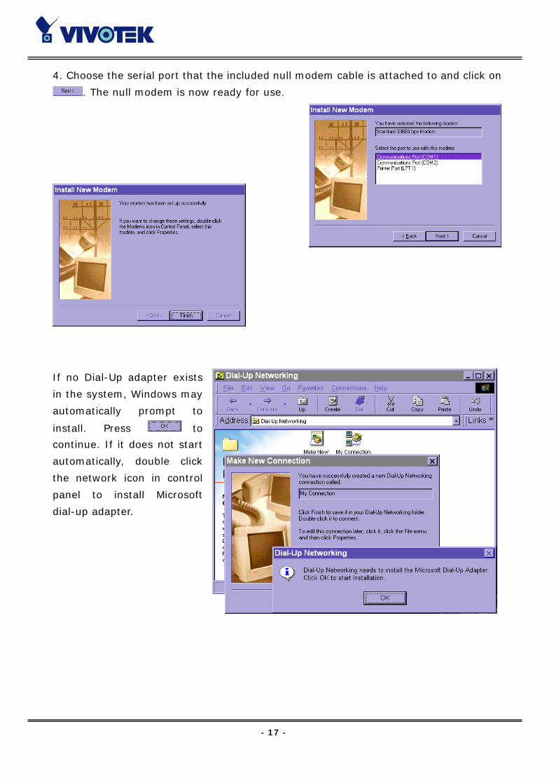
4. Choose the serial port that the included null modem cable is attached to and click on
. The null modem is now ready for use.
If no Dial-Up adapter exists
in the system, Windows may
automatically prompt to
install. Press to
continue. If it does not start
automatically, double click
the network icon in control
panel to install Microsoft
dial-up adapter.
- 18 -
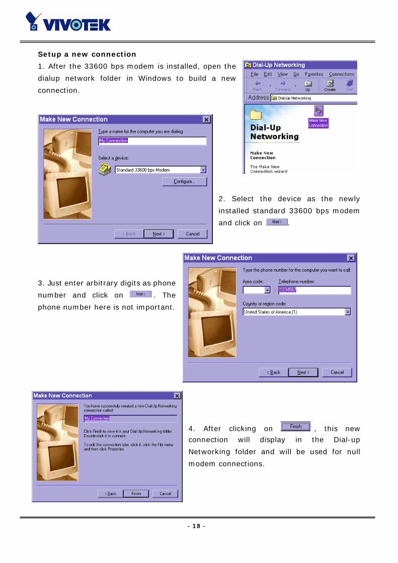
Setup a new connection
1. After the 33600 bps modem is installed, open the
dialup network folder in Windows to build a new
connection.
2. Select the device as the newly
installed standard 33600 bps modem
and click on .
3. Just enter arbitrary digits as phone
number and click on . The
phone number here is not important.
4. After clicking on , this new connection will display in the Dial-up
Networking folder and will be used for null
modem connections.

- 19 -
5. Right-click on the newly setup connection icon for entering properties.
6. In the first General page, clear "Use area
code and Dialing Properties" option and
click on .
7. Select 115200 as the speed and click on .
8. On the second page, only check "Enable software
compression" and "TCP/IP" while leaving others
blank. Keep other settings as default values and click
on .
- 20 -
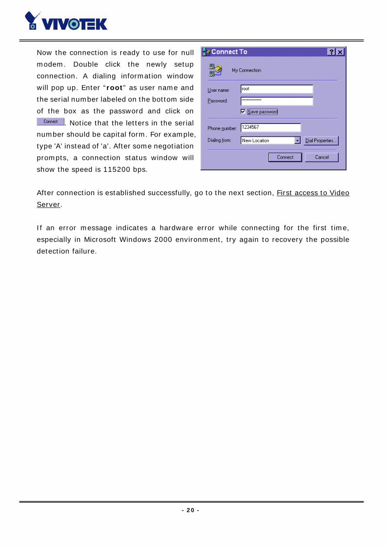
Now the connection is ready to use for null
modem. Double click the newly setup
connection. A dialing information window
will pop up. Enter “root” as user name and
the serial number labeled on the bottom side
of the box as the password and click on
. Notice that the letters in the serial
number should be capital form. For example,
type 'A' instead of 'a'. After some negotiation
prompts, a connection status window will
show the speed is 115200 bps.
After connection is established successfully, go to the next section, First access to Video
Server.
If an error message indicates a hardware error while connecting for the first time,
especially in Microsoft Windows 2000 environment, try again to recovery the possible
detection failure.
- 21 -
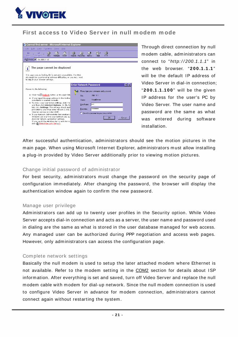
First access to Video Server in null modem mode
Through direct connection by null
modem cable, administrators can
connect to “http://200.1.1.1” in
the web browser. “200.1.1.1”
will be the default IP address of
Video Server in dial-in connection;
“200.1.1.100” will be the given
IP address for the user's PC by
Video Server. The user name and
password are the same as what
was entered during software
installation.
After successful authentication, administrators should see the motion pictures in the
main page. When using Microsoft Internet Explorer, administrators must allow installing
a plug-in provided by Video Server additionally prior to viewing motion pictures.
Change initial password of administrator For best security, administrators must change the password on the security page of
configuration immediately. After changing the password, the browser will display the
authentication window again to confirm the new password.
Manage user privilege Administrators can add up to twenty user profiles in the Security option. While Video
Server accepts dial-in connection and acts as a server, the user name and password used
in dialing are the same as what is stored in the user database managed for web access.
Any managed user can be authorized during PPP negotiation and access web pages.
However, only administrators can access the configuration page.
Complete network settings Basically the null modem is used to setup the later attached modem where Ethernet is
not available. Refer to the modem setting in the COM2 section for details about ISP
information. After everything is set and saved, turn off Video Server and replace the null
modem cable with modem for dial-up network. Since the null modem connection is used
to configure Video Server in advance for modem connection, administrators cannot
connect again without restarting the system.
- 22 -
First access to Video Server in modem mode If the dial-out is not prohibited and the attached modem is recognized, Video Server will
send out the system startup log and connection log by email or FTP according to user’s
settings as soon as the system is ready. That can be used to verify if the settings work.
Then Video Server will always wait for someone to dial in. To dial in Video Server, setup
a connection in dialup network on PC where the phone number is the phone line of Video
Server. After connecting successfully, start the Web browser and connect to
“http://200.1.1.1”. In this case, Video Server runs as a dial-up server and assigns the IP
address of “200.1.1.100” to the PC at the other end. While seeing the authentication
message window, type “root” as user name and the serial number of Video Server as the
initial password. The point-to-point connection allows users connecting Video Server for
surveillance at any time.
If the administrator has setup some conditions in the application Web page or the script
file, Video Server will automatically dial out based on the administrator's configuration.
Refer to the Application section in the Chapter Definitions of Configuration for special
security applications.
- 23 -
How to Use
Open your familiar web browser and connect to Video Server just like a general web site
and the video will present on demand. Make sure the web address of the target Video
Server is accurate.
Authentication
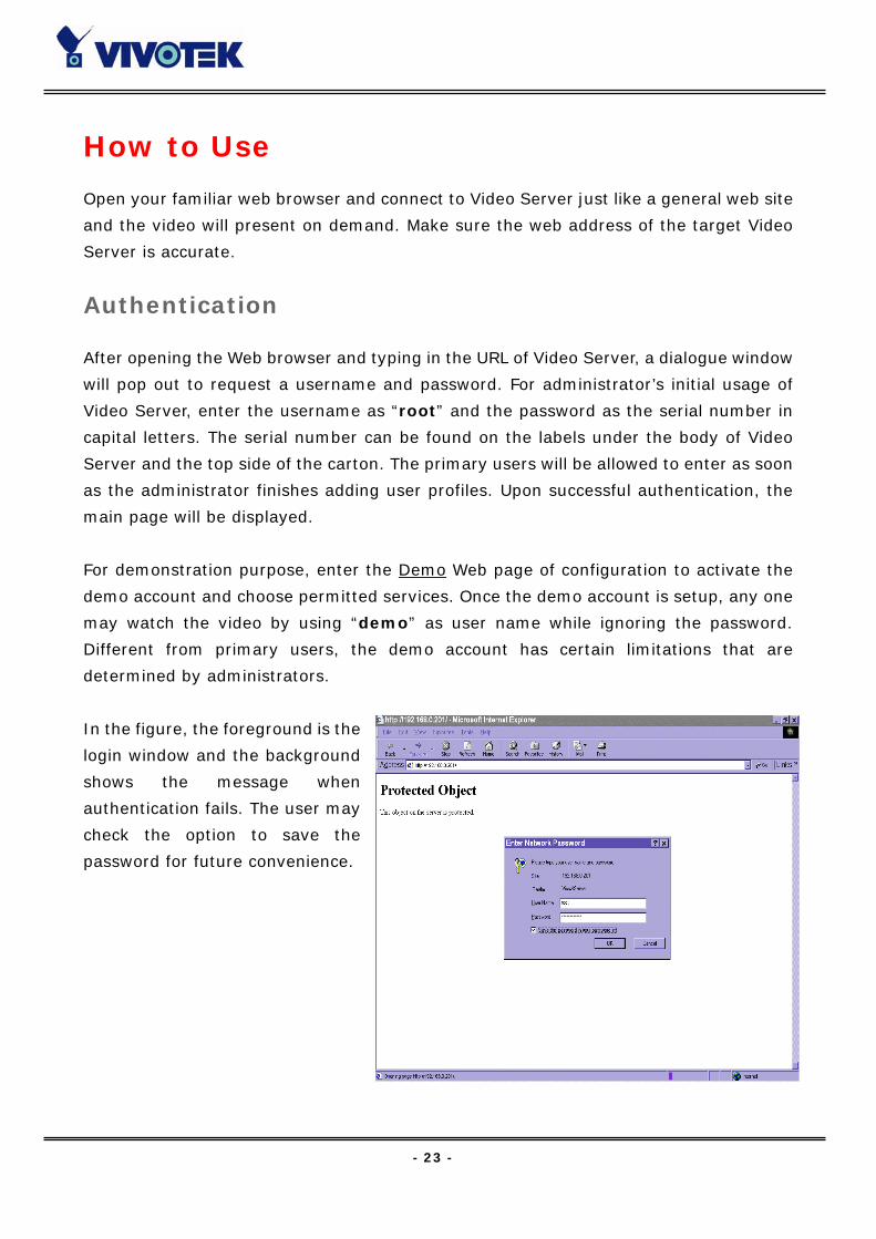
After opening the Web browser and typing in the URL of Video Server, a dialogue window
will pop out to request a username and password. For administrator’s initial usage of
Video Server, enter the username as “root” and the password as the serial number in
capital letters. The serial number can be found on the labels under the body of Video
Server and the top side of the carton. The primary users will be allowed to enter as soon
as the administrator finishes adding user profiles. Upon successful authentication, the
main page will be displayed.
For demonstration purpose, enter the Demo Web page of configuration to activate the
demo account and choose permitted services. Once the demo account is setup, any one
may watch the video by using “demo” as user name while ignoring the password.
Different from primary users, the demo account has certain limitations that are
determined by administrators.
In the figure, the foreground is the
login window and the background
shows the message when
authentication fails. The user may
check the option to save the
password for future convenience.
- 24 -
Installing Plug-in
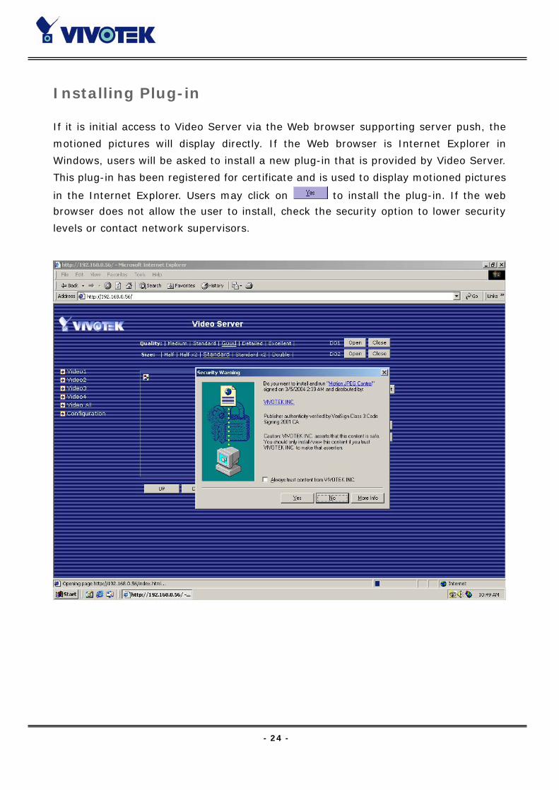
If it is initial access to Video Server via the Web browser supporting server push, the
motioned pictures will display directly. If the Web browser is Internet Explorer in
Windows, users will be asked to install a new plug-in that is provided by Video Server.
This plug-in has been registered for certificate and is used to display motioned pictures
in the Internet Explorer. Users may click on to install the plug-in. If the web
browser does not allow the user to install, check the security option to lower security
levels or contact network supervisors.

- 25 -
Main Page
Basic functions are displayed in main entrance page of Video Server. The first figure
below is graphic mode that has better visual effect and the second one is text mode that
will shorten download time. The main page may look different depending on the PTZ
driver or the privilege of the user.
Graphic mode
Text mode is
default if any
image button is not
available.
Text mode
- 26 -
Video input selection Switch the video source among up to four cameras connected to Video Server. When
clicking on the quad display button, a special quad display of all video inputs is available
for simultaneous monitoring. The picture refresh rate of quad display is slower than the
single input because it takes time to capture the valid image after changing the video
source. The actually appearing buttons depend on the system settings.
Video quality selection It allows users to adjust the video quality for speed or smoothness. The performance is
also subject to the network bandwidth and the number of users. Five options are
available to be chosen from “Medium” to “Excellent”. “Medium” quality means the
picture has the quickest refresh rate but the worst image quality and “Excellent” quality
means the picture has the slowest refresh rate but the best image quality.
Video size selection It allows users to adjust the image size with consideration of bandwidth and image
resolution. Five options are available including “Half”, “Half×2”, “Standard”,
“Standard×2” and “Double”. “Half×2” consumes the same bandwidth as “Half” but
has the same size with “Standard”. Of course the visual effect is worse than “Standard”.
“Standard×2” compared to “Double” is similar to the case. “Half×2” is especially suits
in the low bandwidth environment like a dial-up network. To fit into the small image area,
timestamp will be skipped in “Half” and “Half×2” modes.
While in the quad display mode, “Half” means the image is composed of half size image
of each channel. “Standard (fast)” will have higher frame rate and “Standard (clear)”
will have higher resolution image.
System configuration There is a button or text link under video buttons for system configuration that only
appears in administrators’ main page.
External digital output control There may be two remote control buttons for each digital output on the main page. If
there are external devices attached to digital outputs, administrators or permitted users

- 27 -
can click on to short “Common” and “Normal Open” pins of the digital output or
click on to short “Common” and “Normal Close” pins of the digital output. To know
more about the digital outputs for external devices, refer to the rear panel introduction
of the Chapter Physical Description.
Motorized camera control If there is any serial device like motorized camera attached and correctly setup to either
COM port, the control panel will appear on permitted users’ main page. The effective
buttons will change color when users move the cursor over. Users can control the
motorized camera in pan and tilt direction as well as zoom and focus. The home button
can return the camera to the center position if the camera supports this command.
Besides the near and far control in focus, an “AUTO” button is provided for setting auto
focus mode. To move the motorized camera more precisely, speed control of pan and tilt
allows users to fine tune the aiming position. Users also can directly click on any point in
the image to force the motorized camera to focus on it. Users can pull down the list of
preset locations to choose any one to move the camera to the preset location that is
pre-defined by administrators. The detailed configurations are described in the related
section in the Chapter Definitions of Configuration.
Custom camera commands There are at most five buttons of custom commands for users to control the attached
motorized cameras in addition to the default pan, tilt, zoom and focus control. The
custom commands mean that administrators can setup some special commands like
activating or deactivating the wiper of dome according to the user’s manual of the
attached motorized device.
- 28 -
System Configuration
Introduction
The system configuration can be easily done remotely on Internet Explorer through the
Web interface. There are two wizards in addition to classified categories of system
configurations. They can give friendly instructions and facilitate the setup job.
Alternately administrators may type directly the URL of system configuration,
“http://<IP address of Video Server>/setup/config.html”, to directly enter the
configuration page. If administrators also want to set certain options through the URL,
read the relative section in the Chapter Advanced Usage for reference. Video Server also
supports FTP to modify the system configuration file, CONFIG.INI, for technical usage.
The details are described in the Chapter Advanced Usage.
Since it is a networking video server, administrators should run “Setup wizard” or well
configure “Security”, “Network” and “Video” at least. To support external serial port
devices, configure “COM1” and “COM2” and then “Camera Setting” in “Video”. To
utilize the built-in features of security and web attraction, run “Application wizard” or
configure “Application” and “Demo”. Besides these features, administrators can adjust
the system date and time in “System”, or have different homepage layout by
configuring “Homepage layout”. Video Server also provides some system maintenance
like “View log file”, “View parameters” and “Factory default”.

- 29 -
Setup Wizard
The setup wizard will guide administrator to enter necessary information including
system name, current date and time, administrator’s password, video configuration and
captions, and network settings. Administrators can exit the procedures anytime to
reserve the current configuration. Finally the setup wizard will ask for reboot to validate
the changes and administrators can decide to reboot later.
Application Wizard
There are two main applications including surveillance system and web attraction by
means of Video Server. The former one will utilize the built-in motion detection and
external sensors to integrate with the existing e-mail or FTP server or external alarms to
constitute a security system. It also possesses the weekly schedule for timed monitoring.
The later one will customize the main page to your personal style and setup accounts for
your possible visitors. The application is perfectly constructed and performed on several
clicks by your fingertip. Administrators can additionally configure the application
parameters in the Application page of configuration for more advanced usage after using
Application wizard.
- 30 -
Definitions of Configuration
System parameters Change host name The “host name” is used for the homepage title of main page and displays as the title
over the video window on the main page. The maximum string length is 40 characters or
20 characters in double-byte-character-systems like Chinese or Japanese.
Adjust date and time There are three ways to adjust system date and time. The easiest is to make Video
Server "Sync with computer time". The second “Manual” is to set the date and time
manually by entering new values. Notice the format in the related field while typing. The
third “Automatic” is to make Video Server automatically synchronize with timeservers
over the Internet every month. It may fail if the assigned NTP server cannot be reached
or Video Server is within a local network. Leaving the NTP server blank will let Video
Server connect to default timeservers. Domain name or IP address format is acceptable
as long as DNS server is available. Do not forget setting the "Time zone" offset for local
settings. Refer to the Appendix C for the time zone of your region. It only affects the hour
in NTP method. Once the check box of “Automatic “is checked, video server will synch
with NTP server periodically. Update interval can be set as hourly, daily, weekly or
monthly in the “Update Interval” item
“Automatically restore DO state after seconds” allows you to restore DO state after
events trigger DO.
Once the settings are changed, click on to validate changes.

- 31 -
Security privilege Change root password To change the administrator’s password, type the new password in both text boxes
identically. What is typed will be displayed as asterisks for security purposes. The
maximum password is 16 characters. After pressing , the web browser will ask
administrators for the new password for access.
Add new users To add a new user, type the new user's name and password, check respective privilege,
and then press to insert the entry. There are a total of twenty user accounts. Each
user can have independent access right of each video channel, external I/O access and
camera control.
Edit user’s privilege If the permitted rights of some user has to be changed, pull down the user list to find the
user name and press . A new window will pop out for administrators to change
password and choose different privilege.
Delete existing users To delete a user, pull down the user list to find the user name to be deleted and press
. A message window will pop up for confirmation.
Enable snapshot mode for more users The maximum users that can view Video Server at the same time are twenty.
Administrators can check “Allow more guests with snapshot mode” to enable the
snapshot mode for more users. Then the users over twenty will have the main page with
snapshot mode instead of normal motion picture. It is practical for web attraction. In
such case, configure the “Snapshot interval” to achieve better performance. The
bigger interval between snapshots, the more users can have snapshot mode work.
- 32 -
Network settings Fix the IP address To eliminate incautious mistakes during installation, Video Server will stay in installation
mode whenever it starts unless "Reset network at next boot" is disabled. This option
can also be disabled using the Installer program. Once the option is disabled, Video
Server will skip installation at the next boot and the Installer program will not find the
installed units. That implies that Video Server cannot be accessed if no one remembers
the IP address, except for restoring factory default settings. However, with this option
disabled Video Server can automatically operate normally after restarting in case of
losing power. This option is ignored in the PPP connection.
Basic network settings Administrators may need to modify the network settings to fit into existing networks.
The subnet mask in some broadband service may differ from the default value
255.255.255.0 and service providers may assign more specific network settings.
Administrators should change the configuration to what given by the service provider.
The configuration may include "IP address", "Subnet mask", "Default router",
"Primary DNS server" and "Secondary DNS server". After changing network settings,
be sure to leave "Reset network at next boot" blank to skip next installation when the
system restarts. Otherwise those network settings will be erased at the next start.
Changing port number of servers For security or network integration, administrators also can hide the server from the
general HTTP port by changing "HTTP port" to other than default 80. “Local FTP
server port” can also be changed to other than default 21. Administrators should have
enough network knowledge to change the default port.
SMTP “SMTP (mail) server 1” The domain name or IP address of the external email server.
“Recipient email address 1” The email address of the recipients for snapshots or log
file. Multiple recipients must be separated by semicolons, ‘;’.
“SMTP account name 1” Some SMTP server requires an account name for logging in.
Refer to your SMTP Administrator for detailed information.
“SMTP password 1” The password for the SMTP server account.
“SMTP (mail) server 2” The domain name or IP address of another email server once
the previous server is unreachable.
“Recipient email address 2” The email addresses of the recipients for the backup
server.
- 33 -
“SMTP account name 2” The account login name for the second SMTP server.
“SMTP password 2” The password is for the second SMTP account name.
“Sender email address” The return email address used in the event the mails fail to be
sent out
FTP settings “Local FTP server port” This can be other than the default Port 21. The user can
change this value from 1 to 65535. After the changed, the external FTP client program
must change the server port of connection accordingly.
“1st FTP server” The domain name or the IP address of the external FTP server. The
following user settings must be correctly configured for remote access.
“1st FTP user name” Granted user name on the external FTP server.
“1st FTP password” Granted password on the external FTP server.
“1st FTP remote folder” Granted folder on the external FTP server. The string must
conform to that of the external FTP server. Some FTP servers cannot accept preceding
slash symbol before the path without virtual path mapping. Refer to the instructions for
the external FTP server for details. The folder privilege must be open for upload.
“Primary FTP passive mode” The Video Server located inside the network protected
by a firewall, data connection for FTP may be prohibited. By selecting passive mode, the
FTP can bypass the rule and allow snapshot upload to proceed. If the passive mode is
selected, the Video Server can automatically attempt for active mode, if the external FTP
server does not support passive mode.
“2nd FTP server” The domain name or IP address of the external FTP server.
“2nd FTP user name” Granted user name on the backup FTP server.
“2nd FTP password” Granted password on the backup FTP server.
“2nd FTP remote folder” Granted folder on the backup FTP server.
“Secondary FTP passive mode” Passive mode setting for the backup FTP server.
In either e-mail or FTP, the primary server information should be entered first. If the
primary server is not set, the related FTP or email will be cancelled. Note that it may take
time to connect to the secondary server after the first one fails and it may affect some
applications when conditions happen too often.
After everything is set, click on . A warning message will pop out for confirmation.
After clicking on , Video Server will automatically restart. If "Reset network at
next boot" is kept checked, perform software installation again. Otherwise Video Server
will boot up according to the new configuration automatically.
- 34 -
Any change made to this page will make the system restart to validate. Make sure
every field is correctly typed before clicking on . If Video Server fails to response
due to erratic settings, perform the restore procedures and run software installation.
Administrators should notice that the basic network settings including IP address,
subnet mask, default router and DNS servers will be cleared when the network interface
is switched to the other between Ethernet and modem.
Video, camera mapping and motion detection Enable video channels Only when the video source is "Enable", the related link will be displayed in the main
page. It is recommended to disable the video inputs without camera to improve the
refresh rate within quad screen function. There are three buttons for “Image setting”,
“Camera setting” and “Motion detection” regarding to each video channel. The details
are described in later paragraphs. The video “Modulation” can be automatically detected
by the system or manually selected by administrators. Administrators can choose any
video channel to be “Default video source” shown in the main page when users connect
at the first time.
Adjust image settings "Time stamp" and "Text on image" will be enclosed in image for reference. The
timestamp is captured from date and time of Video Server that is maintained by an
on-board real-time clock. "Color" setting is independent of the connected camera and
“B/W” option can speed up the encoder a little. “Default quality” option here will be
the default quality when users first connect to Video Server. “Default size” option here
will be the default size of video window when users first connect to Video Server. To
customize for different camera, administrators can adjust "Brightness", "Contrast",
"Hue" and "Saturation" for video compensation of each channel. While adjusting,
administrators can click on to check prior to the setting in memory. If the
adjustment is not good, administrators can click on to restore the original
settings without change. To facilitate the settings of four video channels, administrators
can click on then every setting in this channel will copy to other channels.
Note that the “Text on image” may need to change for each channel. After configuration
done, click on to close this window. If parameters are changed without saving,
they will be used until the next system startup.
- 35 -
Maximum frame rate This limits the maximal refresh frame rate.
Bandwidth utilization limit Each Video Server can be limited in bandwidth utilization by administrators according to
its priority and importance of location. "Bandwidth limit" is most useful to balance
network utilization when multiple Video Server’s are installed in the same network. It is
more effective than changing image quality only and achieves better performance with
adequate image size and quality.
Configure attached motorized camera In addition to configuring PTZ camera driver in COM1 or COM2 page, administrators have
to define the relationship between video channel and camera. If there is any PTZ camera
attached, administrators should select the “Camera type” as “PTZ camera”, set the
attached COM port and the ID of the PTZ camera. The ID is specific to the camera and
necessary for multiple camera control. Refer to the manual of camera for ID settings.
After clicking on , the preset function will appear in the lower half of window. There
are up to twenty positions can be memorized. Administrators can move the camera and
then enter the position name and save. The old “Preset position” can also be pulled
down to delete.
The camera control will be activated only when both the attached “COM” port and
“Camera Setting” are correctly configured. The camera ID may be relative to some DIP
switch on the PTZ camera. Administrators may need to read the manual of the PTZ
camera for specific information.
Configure motion detection Each channel can have its own settings of motion detection independently. The settings
including “Object size” and “Sensitivity” allow administrators fine tune to fit into the
environment. The “Object size” decides the space ratio of motioned objects over the
monitored screen. The “Sensitivity” sets the measurable difference between two
sequential images that would indicate motion. The larger object size and lower
sensitivity will make Video Server ignore small variations in images. While the motion
amplitude of some object in the monitored screen is over the settings, a white M in red
background will indicate at the upper-right corner of the window.
Motion detection is provided as reference because it is very environment-dependent.
Especially working by the very sensitive settings, some triggered events may be
considered as false alarms though there is tiny difference happening indeed. It can be
- 36 -
affected by florescent light flashing, shadow shifting, and so on.
Set video modulation There are basically two types of video modulation; one is NTSC and the other is PAL.
Administrators can select “AUTO” to make Video Server automatically detect the correct
type.
Select default video source Administrators can choose video channel 1 to 4 or quad screen to be the default video
source on the homepage when users connect to Video Server. If the default video source
is disabled in the user’s privilege, the prohibited screen will display instead.
- 37 -
COM1 port configuration Choose serial interface There are two types of serial interfaces supported by COM1 but only one interface can be
used at one time. Administrators must set the correct “Interface mode” between
RS232 and RS485 according to the attached device.
Choose device driver If the attached device is PTZ driver, administrators should select the appropriate PTZ
model. Refer to our Web site for newly supported PTZ drivers. If the attached PTZ
camera is not in the support list, administrators can select “Custom Camera” to enter
the proprietary commands for pan, tilt, zoom and focus control. If it is not a PTZ camera
but another serial device like video multiplexer, administrators can select the “Generic
CGI command” to control the device via CGI commands. See the URL of External
Device Control section in the Chapter Advanced Function for details.
COM port configuration After saving the driver type, the COM port configuration will show up for entering the
correct settings that depends on the camera type. Refer to the Appendix Settings for
Supported PTZ Cameras for default settings of supported PTZ camera including baud
rate, data bits, stop bit and parity bit.
Custom commands Video Server provides five more custom commands other than general pan, tilt, zoom
and preset functions. Administrators can click on and refer to the instruction manual of the attached device to setup frequently used functions. The
"Command" should be entered in ASCII format; Video Server will translate it into binary
code and send it out through the serial port. For instance, a text string of "8101ABCDEF"
will be translated into five bytes of hexadecimal 81, 01, AB, CD and EF. The maximal
length of a command string is 60 which is equivalent to 30 hexadecimal bytes. "Display
string" is for text on command buttons and should be less than 8 characters. If the
“Custom Camera” is selected, there will be more commands for PTZF regarding to the
custom camera.
- 38 -
COM2 port configuration and modem Choose device driver There are three types of device drivers that can be attached to COM2. The modem is
supported by COM2 more than COM1 but only RS232 interface is supported.
Administrators should select the device driver and click on save, then the related
configuration will show in the lower half of the page. If the modem is selected, ISP
information is necessary.
COM port configuration After saving the driver type, the COM port configuration will show up for entering the
correct settings that depends on the camera type. Refer to the Appendix Settings for
Supported PTZ Cameras for default settings of supported PTZ camera including baud
rate, data bits, stop bit and parity bit.
Custom commands
will appear when administrators select PTZ driver. The usage is similar to COM1. If administrators select “Modem”, refer to the next paragraph for details.
ISP information setup In PPP interface, a modem option will show instead of camera control 2. Configurations
include modem initialization and outside dial-up server. If the users will setup with
external sensors and alarms for property security, dial-out is needed to send some
snapshot-attached e-mails when the preset conditions are triggered. In such
applications, also remember to choose Network option to enter mail server address and
recipient's e-mail address. If "Dialout allowed" is not checked, Video Server will not
send out any snapshots when events occur and the settings except for "Initial modem
command" in this page will have no effect. The system will preset the attached modem
to eliminate echo and mute line sound. To initialize the modem with further commands,
type into the edit box. The prefix "AT" should be included.
Administrators should choose an appropriate "Dial Method" according to the local POTS
environment. An incorrect dialing prefix may cause Video Server to fail when dialing out.
"Redial attempts" means how many times Video Server should try to connect to each
ISP. Setting the value in "Disconnect after minutes" will force Video Server to drop the
connection when there is no activity on the connection for the specific period. The range
of this period is from 1 to 240 minutes, with 0 indicating a continuous connection.
Administrators may let Video Server keep the connection for a while to allow connections
from outside. The IP address given by the ISP can be taken from the connection log that
- 39 -
is mailed or uploaded when dial-up connection is successful. Setting the value to zero will
make Video Server always keep the connection.
Based on the settings of DI/DO in the application, the system will send mails or upload
via FTP with image attachment upon the event occurring. In that case Video Server will
need a network connection and automatically dial out to the pre-configured server
outside. When a connection is successfully established, Video Server will send out a
connection log to notify given network settings. For those installations that may switch
the network interface between Ethernet and PPP, administrators should notice that the
settings of FTP or SMTP servers might be different from what are in an Ethernet
environment. If the network interface is changed, administrators may need to configure
them in advance.
Video Server will try the second ISP as a backup when the first ISP fails and exceeds the
redial attempts. "ISP phone number" should be the complete phone number including
country code and area code if necessary. "Login username" and "Login password"
are used to pass the PPP negotiation requested by the ISP server. Note that the pair of
login name and password is dependent on the ISP and is different from what is used in
the authentication process in web access.
- 40 -
Application constitution Administrators can use combinations of options on the application page to perform many
useful security applications. Video Server provides two application modes; one is
performed according to the settings on the web page, the other is performed according
to the external command script. Though most settings will automatically be done by the
Application Wizard, administrators still can adjust the settings from this page.
Weekly schedule A useful weekly schedule is provided for daily security application. Administrators can
select weekdays from Monday to Friday with the daily schedule from 9:00 am to 6:00 pm
that no one is at home to perform any event checking. If the security system needs to be
installed in office that no one is there during the nights or weekend, administrators just
set the time period as above, then check “All the time except for the above
schedule” for opposite operations.
External command script Administrators can write a script named SCRIPT.TXT to perfectly match the additional
software according to the Command Script for Complex Applications section in the
Chapter Advanced Functions. After uploading this script to Video Server via FTP, check
the option “Enable the external script file to exclude the following settings”.
Otherwise Video Server will operate according to the settings below.
Event operation Video Server provides general options for two basic applications, event operation for
security and sequential operation for web attraction. In event operation,
administrators have to setup some conditions to check and some actions to happen
consequently. The conditions include motion detection on any video channel and the
status of any digital inputs. While checking motion in video, administrators should click
on the monitored video channel to configure the appropriate parameters. In the newly
opened window, percentage of object size over whole window and sensitivity can be
fine tuned to fit into the environment. If any motion is over the settings, an ‘M’ will
appear on the upper-right corner of image for indication. The ‘M’ will appear in the image
to indicate some motion is detected as long as “Show alert in image” is checked. If
there are any sensors attached to the digital inputs, administrators can set the state to
fire alarm. There are four states of “High”, “Low”, “Rising” and “Falling” plus “Disable”.
The edge trigger like “Rising” or “Falling” is generally used to detect the emerging signal
from the external sensor. Once any event happens, administrators can select “DO
action” and/or send snapshots that are taken right at the moment. There is also a
- 41 -
“Delay second(s) after event” option to drive some device attached to the digital
outputs several seconds after the event happens. If administrators want to receive some
snapshots to check the event, select the snapshot channels and check “Send snapshot
while trigger condition(s) match”. Video Server will take three snapshots of
pre-event, the moment of event, and post-event for selected video channels. If the
snapshots are not enough, more snapshots can be taken after the event by configuring
“Take snapshot(s)” and the “interval after the event” in unit of tenth second. Three
snapshots of each channel can also be downloaded via FTP or HTTP URL. Refer to the
Download Event-triggered Snapshots section for details.
Sequential operation With this feature, Video Server can upload snapshots periodically to external server as a
live video source. The interval can be set from tenth second to several hours. The
external server must be setup correctly in the Network configuration page.
Sending method Either event mode or sequential mode can select one method between email and FTP.
The companied external server must be setup correctly in advance. If email is chosen,
the snapshots of selected video channels will be attached in the emails. If FTP is chosen,
administrators can choose to add date and time in the file name of snapshots. If the
snapshots are used as the live video source, the date and time suffix can be eliminated
to update the same source file.
View snapshots Video Server will take three snapshots of pre-event, the moment of event, and
post-event for selected video channels. You can view these three snapshots by click
“view snapshots” button. Refer to the Download Event-triggered Snapshots section for
details..
The option “Show alert in image” may be set when running application wizard or
configuring motion detection. Administrators should manually uncheck it if no indication
of motion detection is needed in the image.

- 42 -
Demonstration account To setup Video Server for demonstration to the public, administrators need to choose the
service(s) to be permitted. After checking “Enable demo account”, users may use
“demo” as general user name and password is not required. To separate the demo
account from primary users can prevent from interfering with the normal operations.
Homepage layout There are two homepage display modes. One is "Image mode" that uses graphics for
links; the other is "Text mode" that mostly uses text for links.
Image mode Administrators may easily give Video Server a different presence of homepage. The
"logo graph" for the system logo at the upper-left corner can be hidden; or the default
image from the system memory can be used; or an external resource can be used by
assigning a URL. The "Background graph" is similar. Default images of the system can
be customized but limited by memory size. Images from external resources can be
larger and more beautiful but will need more time to load. If the background is skipped,
the background color will fill the browser window. Administrators also can give the
system logo a "Logo link" to connect to another web site while clicked. The "Font color"
and "Background color" can be chosen from sixteen colors as you like. See the
Customize graphics in homepage section in the Chapter Advanced Functions for how to
replace the default images of log, background and buttons of video switch.
Text mode The "video string" for video links can be modified with maximum 16 characters. That
will make users more easily know where the cameras installed like “Main Entrance”,
“Warehouse” instead of “video1”, “video2”. The camera control panel is also replaced by
text buttons.
If any necessary image is lost while homepage layout is image mode, Video Server
will switch to text mode automatically.
- 43 -
View log file There is some useful information in the system log including current system
configuration and activity history with timestamp for tracking.
View parameters The whole system parameters will be categorized listed for administrators to check. The
content is the same as CONFIG.INI.
Factory default It is used to restore the factory default settings. This means any changes made before
will be lost and the system will be reset to the initial status as shipping out of the factory.
After confirmation, the system will restart and require the software installation to setup
the network.
- 44 -
Advanced Functions
Capture Up-to-date Still Images
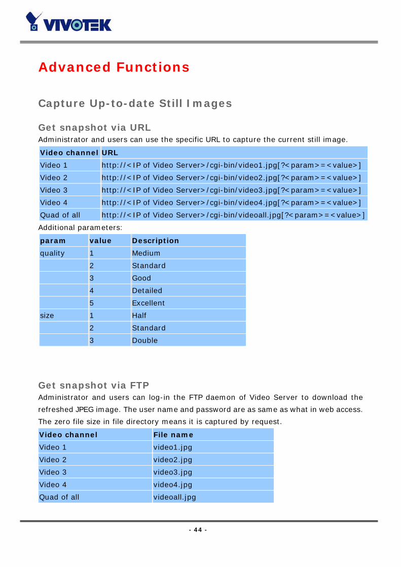
Get snapshot via URL Administrator and users can use the specific URL to capture the current still image.
Additional parameters:
Get snapshot via FTP Administrator and users can log-in the FTP daemon of Video Server to download the
refreshed JPEG image. The user name and password are as same as what in web access.
The zero file size in file directory means it is captured by request.
Video channel URL
Video 1 http://<IP of Video Server>/cgi-bin/video1.jpg[?<param>=<value>]
Video 2 http://<IP of Video Server>/cgi-bin/video2.jpg[?<param>=<value>]
Video 3 http://<IP of Video Server>/cgi-bin/video3.jpg[?<param>=<value>]
Video 4 http://<IP of Video Server>/cgi-bin/video4.jpg[?<param>=<value>]
Quad of all http://<IP of Video Server>/cgi-bin/videoall.jpg[?<param>=<value>]
param value Description
quality 1 Medium
2 Standard
3 Good
4 Detailed
5 Excellent
size 1 Half
2 Standard
3 Double
Video channel File name
Video 1 video1.jpg
Video 2 video2.jpg
Video 3 video3.jpg
Video 4 video4.jpg
Quad of all videoall.jpg

- 45 -
Get Continuous Images
Select video source and quality and size /cgi-bin/video.jpg[?<param>=<value>]
Display all video /cgi-bin/quad.jpg[?<param>=<value>]
param value Description
cam 1 Video 1
2 Video 2
3 Video 3
4 Video 4
quality 1 Medium
2 Standard
3 Good
4 Detailed
5 Excellent
size 1 Half
2 Standard
3 Double
4 Half x 2
5 Standard x 2
param value Description
quality 1 Medium
2 Standard
3 Good
4 Detailed
5 Excellent
size 1 Half
2 Standard (fast)
3 Standard (clear)
4 Half x 2

- 46 -
Video Embedded in Customers’ Homepage
In additional to the URL, some scripts should be added to download a plug-in for motion
pictures. The following example simply displays title text and a real-time video window
in Internet Explorer or Netscape. The user name and password should be configured in
advance. Those who are familiar with HTML can easily add more components or rewrite
a more vivid and useful homepage.
<html>
<head><title>Video Server Sample Page</title></head>
<body>
<h2>Video Server Sample Page</h2>
<script language="JavaScript">
<!--
if ((navigator.appName == "Microsoft Internet Explorer")&&(navigator.platform !=
"MacPPC")) {
document.write("<OBJECT ID=\"MjpegControl\" WIDTH=352 HEIGHT=240");
document.write(" CLASSID=\"CLSID:EAA105FE-7BBD-4196-8B96-D46743894195
\" ");
document.write("CODEBASE=\"http://username:[email protected]/plugin
/mjpegcontrol.cab#version=1,0,0,4\">");
document.write("<PARAM NAME=\"VSize\" VALUE=\"2\">");
document.write("<PARAM NAME=\"Url\" VALUE=\"http://username:password@
192.168.0.201/cgi-bin/video.jpg");
document.write("?cam=1&quality=3&size=2\">");
document.write("</OBJECT>");
} else {
document.write("<img width=352 height=240");
document.write("src=\"http://192.168.0.201/cgi-bin/video.jpg?cam=1&quality=3
&size=2\">");
}
//-->
</script>
</body>
</html>

- 47 -
Download Event-triggered Snapshots
There are twelve video image files for four video channels of three stages: pre-alarm, the
moment when triggered and post-alarm. Only the snapshots captured by the last event
are preserved. Administrator and users can use FTP or URL to get the saved snapshots.
They can also be browsed from the application page in system configuration.
Get triggered snapshots via URL /cgi-bin/snapshot.jpg?file=<value>
Video channel
Snapshot stage
Video 1 Video 2 Video 3 Video 4
snapshot before event pre1 pre2 pre3 pre4
snapshot upon event trg1 trg2 trg3 trg4
snapshot after event pos1 pos2 pos3 pos4
Get triggered snapshots via FTP
File name Pre-alarm Upon alarm Post-alarm
Video 1 v1pre.jpg v1trg.jpg v1pos.jpg
Video 2 v2pre.jpg v2trg.jpg v2pos.jpg
Video 3 v3pre.jpg v3trg.jpg v3pos.jpg
Video 4 v4pre.jpg v4trg.jpg v4pos.jpg
- 48 -
Uploading Snapshots Periodically
Upload snapshots to external FTP server In sequential mode, Video Server will send out snapshots according to interval and
period settings. If snapshot files are intended for quick updates, it is better to skip date
and time suffix. The file name will then be video1.jpg, video2.jpg, video3.jpg and
video4.jpg for four channels. If the snapshots are used for occasional monitoring, suffix
with date and time can help administrators classify them easily.
Send snapshots to external SMTP (email) server Comparing to the FTP method, email will induce more delay. But the email can notify
users for prompt action.
- 49 -
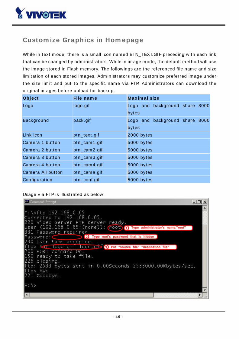
Customize Graphics in Homepage
While in text mode, there is a small icon named BTN_TEXT.GIF preceding with each link
that can be changed by administrators. While in image mode, the default method will use
the image stored in Flash memory. The followings are the referenced file name and size
limitation of each stored images. Administrators may customize preferred image under
the size limit and put to the specific name via FTP. Administrators can download the
original images before upload for backup.
Usage via FTP is illustrated as below.
Object File name Maximal size
Logo logo.gif Logo and background share 8000
bytes
Background back.gif Logo and background share 8000
bytes
Link icon btn_text.gif 2000 bytes
Camera 1 button btn_cam1.gif 5000 bytes
Camera 2 button btn_cam2.gif 5000 bytes
Camera 3 button btn_cam3.gif 5000 bytes
Camera 4 button btn_cam4.gif 5000 bytes
Camera All button btn_cama.gif 5000 bytes
Configuration btn_conf.gif 5000 bytes

- 50 -
Command Script for Complex Applications
Besides the application wizard, Video Server provides a more professional command
script for advanced applications. The command script will be executed exclusively with
the settings in Application page of system configuration except for the weekly schedule.
To build the advanced application, follow the steps below.
1. Use any text editor to edit the appropriate command script according to the command
format. The script size cannot exceed 500 bytes.
2. Save the script as a file named “SCRIPT.TXT”.
3. Use FTP with administrator’s privilege to upload the script file.
4. Enter the Application page in system configuration to define the time period in weekly
schedule. If it is supposed to run any time, keep the original settings but check the
option “All the time except for the above schedule”.
5. Check the option “Enable the external script file to exclude the following settings” to
activate the command script.
Command format [Event][“Operator”Event]……=[Action][+Action]……;
Event [“Digital Input Number””Digital Input State”]
[“M” “Channel Number…”]
[“Channel Number””Video Input State”]
Operator “+”: (OR)
“*”: (AND)
Action [(“Delay Time”)“Digital Output Number””Digital Output State”]
[“V”“Channel Number”“P”“Preset Location Number”]
[“W”{“IP”:“Port”}{“Message”}]
[“U”“Method”]
[“S”“Channel Number…”]
[“N”{“filename”}];
Parameter explanation Item between brackets means optional but at least one item should exist.
“Digital input number”: 1 ~ 4

- 51 -
“Digital input state”: H (high), L (low), / (low to high), \ (high to low)
“M”: motion detection event.
“Channel Number”: A, B, C, D for channel 1, 2, 3, 4
“Video input state”: / (signal from loss to presence), \ (signal from presence to
loss), X (as long as signal loss)
“Digital output number”: 1 ~ 2
“Digital output state”: C (NC), O (NO)
“V”: set video channel to go to preset location
“P”: set preset location number to go to preset location
“W”: send warning to server
“IP”: server IP
“Port”: server port
“Message”: texts to be sent to the server
“U”: upload snapshots
“Method”: ‘F’ is by FTP, ‘M’ is by e-mail
“S”: take snapshot on channels
“N”: define the format of the filename
“;”: end of line
The filename format is, %c channel number
%a image characterization (pre, trg, pos)
%y year
%M month
%d day
%h hour
%m minute
%s second
%t tenth second
- 52 -
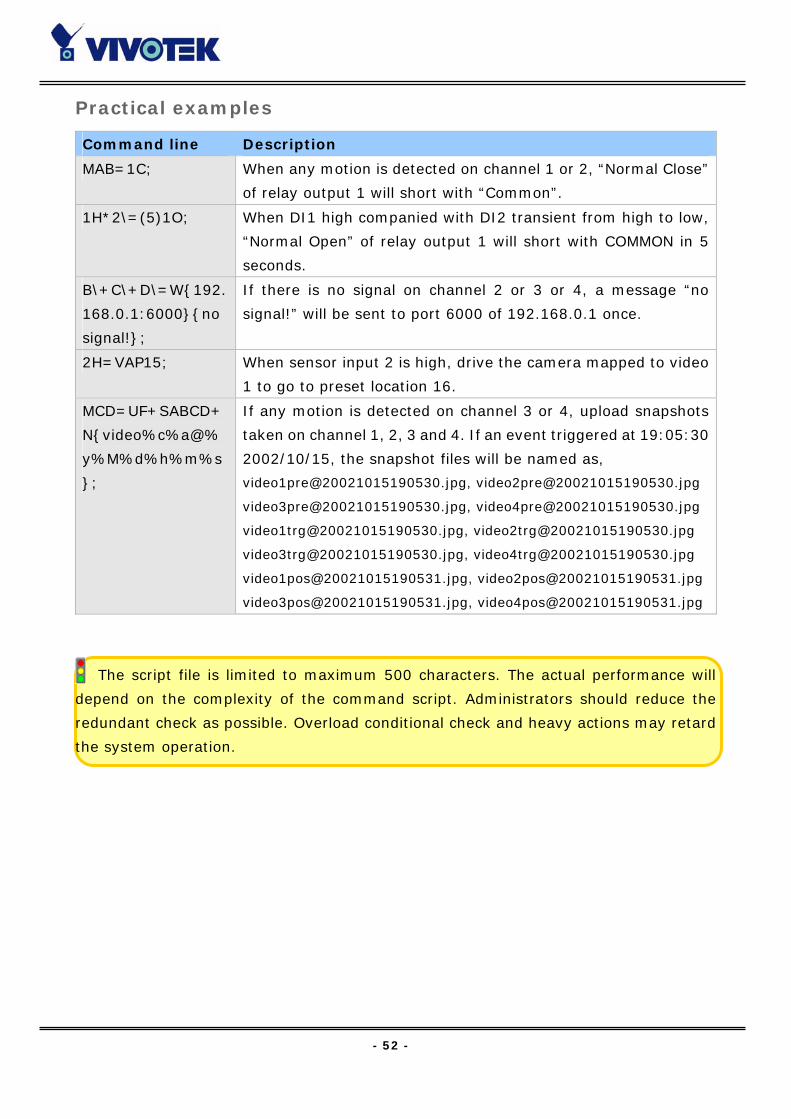
Practical examples
The script file is limited to maximum 500 characters. The actual performance will
depend on the complexity of the command script. Administrators should reduce the
redundant check as possible. Overload conditional check and heavy actions may retard
the system operation.
Command line Description
MAB=1C; When any motion is detected on channel 1 or 2, “Normal Close”
of relay output 1 will short with “Common”.
1H*2\=(5)1O; When DI1 high companied with DI2 transient from high to low,
“Normal Open” of relay output 1 will short with COMMON in 5
seconds.
B\+C\+D\=W{192.
168.0.1:6000}{no
signal!};
If there is no signal on channel 2 or 3 or 4, a message “no
signal!” will be sent to port 6000 of 192.168.0.1 once.
2H=VAP15; When sensor input 2 is high, drive the camera mapped to video
1 to go to preset location 16.
MCD=UF+SABCD+
N{video%c%a@%
y%M%d%h%m%s
};
If any motion is detected on channel 3 or 4, upload snapshots
taken on channel 1, 2, 3 and 4. If an event triggered at 19:05:30
2002/10/15, the snapshot files will be named as,
[email protected], [email protected]
[email protected], [email protected]
[email protected], [email protected]
[email protected], [email protected]
- 53 -
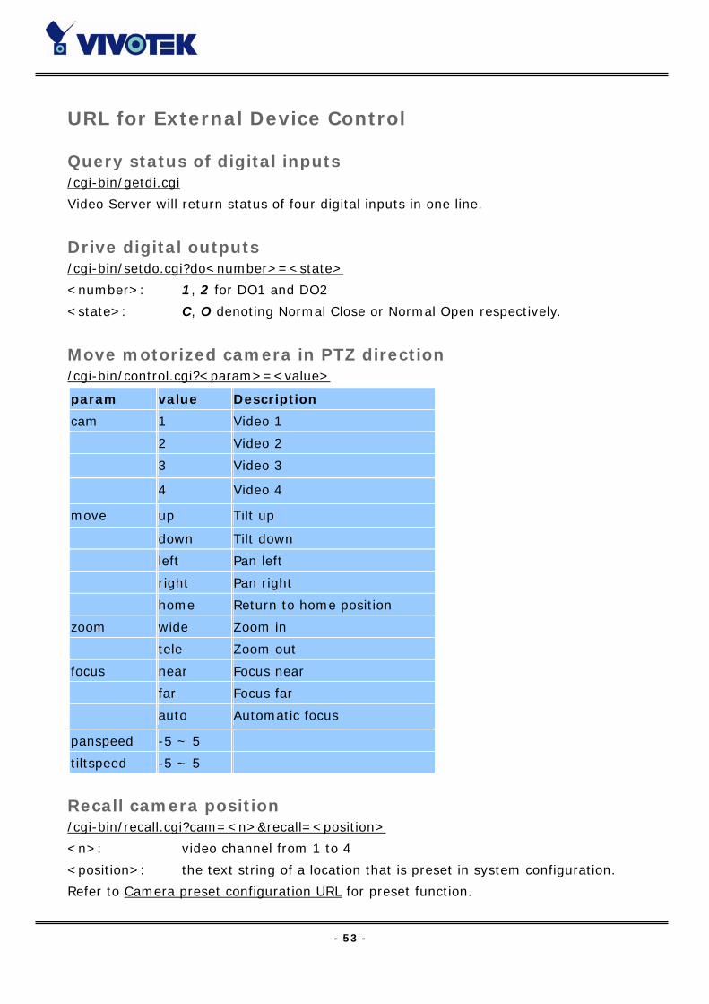
URL for External Device Control
Query status of digital inputs /cgi-bin/getdi.cgi
Video Server will return status of four digital inputs in one line.
Drive digital outputs /cgi-bin/setdo.cgi?do<number>=<state>
<number>: 1, 2 for DO1 and DO2
<state>: C, O denoting Normal Close or Normal Open respectively.
Move motorized camera in PTZ direction /cgi-bin/control.cgi?<param>=<value>
Recall camera position /cgi-bin/recall.cgi?cam=<n>&recall=<position>
<n>: video channel from 1 to 4
<position>: the text string of a location that is preset in system configuration.
Refer to Camera preset configuration URL for preset function.
param value Description
cam 1 Video 1
2 Video 2
3 Video 3
4 Video 4
move up Tilt up
down Tilt down
left Pan left
right Pan right
home Return to home position
zoom wide Zoom in
tele Zoom out
focus near Focus near
far Focus far
auto Automatic focus
panspeed -5 ~ 5
tiltspeed -5 ~ 5
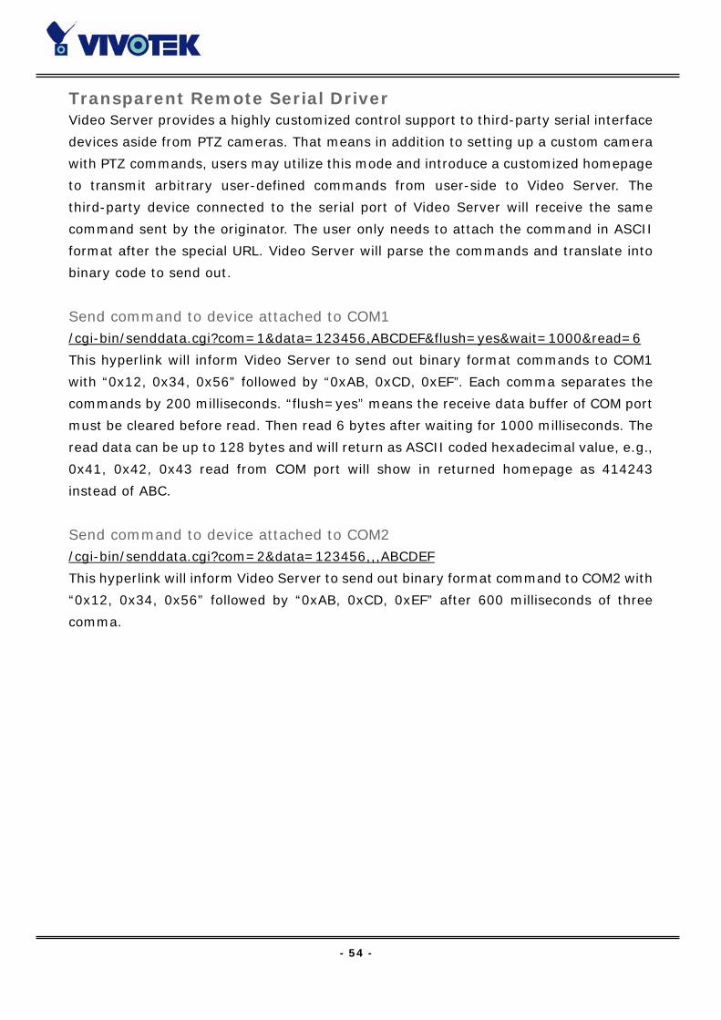
- 54 -
Transparent Remote Serial Driver Video Server provides a highly customized control support to third-party serial interface
devices aside from PTZ cameras. That means in addition to setting up a custom camera
with PTZ commands, users may utilize this mode and introduce a customized homepage
to transmit arbitrary user-defined commands from user-side to Video Server. The
third-party device connected to the serial port of Video Server will receive the same
command sent by the originator. The user only needs to attach the command in ASCII
format after the special URL. Video Server will parse the commands and translate into
binary code to send out.
Send command to device attached to COM1 /cgi-bin/senddata.cgi?com=1&data=123456,ABCDEF&flush=yes&wait=1000&read=6
This hyperlink will inform Video Server to send out binary format commands to COM1
with “0x12, 0x34, 0x56” followed by “0xAB, 0xCD, 0xEF”. Each comma separates the
commands by 200 milliseconds. “flush=yes” means the receive data buffer of COM port
must be cleared before read. Then read 6 bytes after waiting for 1000 milliseconds. The
read data can be up to 128 bytes and will return as ASCII coded hexadecimal value, e.g.,
0x41, 0x42, 0x43 read from COM port will show in returned homepage as 414243
instead of ABC.
Send command to device attached to COM2 /cgi-bin/senddata.cgi?com=2&data=123456,,,ABCDEF
This hyperlink will inform Video Server to send out binary format command to COM2 with
“0x12, 0x34, 0x56” followed by “0xAB, 0xCD, 0xEF” after 600 milliseconds of three
comma.

- 55 -
URL of System Maintenance
Download System Log via FTP Besides viewing the system log from the web page, administrators can download the
system log file, SYSTEM.LOG, via FTP. To log into the FTP daemon, enter “root” as the
user name and the same administrator’s password used in Web access.
Restart System via URL /cgi-bin/reset.cgi
Restart Video Server without warning.
Restore Factory Default Settings via URL /cgi-bin/restore.cgi
Video Server will automatically restart after restoring factory default configurations.
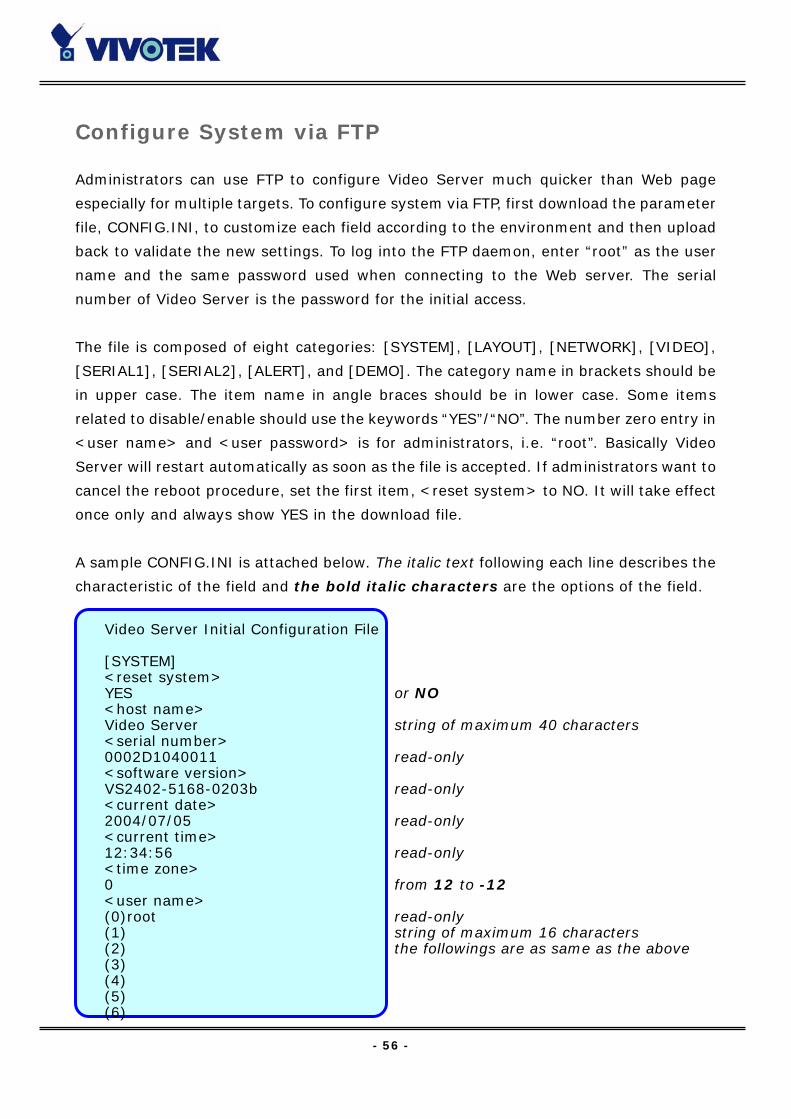
- 56 -
Configure System via FTP
Administrators can use FTP to configure Video Server much quicker than Web page
especially for multiple targets. To configure system via FTP, first download the parameter
file, CONFIG.INI, to customize each field according to the environment and then upload
back to validate the new settings. To log into the FTP daemon, enter “root” as the user
name and the same password used when connecting to the Web server. The serial
number of Video Server is the password for the initial access.
The file is composed of eight categories: [SYSTEM], [LAYOUT], [NETWORK], [VIDEO],
[SERIAL1], [SERIAL2], [ALERT], and [DEMO]. The category name in brackets should be
in upper case. The item name in angle braces should be in lower case. Some items
related to disable/enable should use the keywords “YES”/“NO”. The number zero entry in
<user name> and <user password> is for administrators, i.e. “root”. Basically Video
Server will restart automatically as soon as the file is accepted. If administrators want to
cancel the reboot procedure, set the first item, <reset system> to NO. It will take effect
once only and always show YES in the download file.
A sample CONFIG.INI is attached below. The italic text following each line describes the
characteristic of the field and the bold italic characters are the options of the field.
Video Server Initial Configuration File [SYSTEM] <reset system> YES or NO <host name> Video Server string of maximum 40 characters <serial number> 0002D1040011 read-only <software version> VS2402-5168-0203b read-only <current date> 2004/07/05 read-only <current time> 12:34:56 read-only <time zone> 0 from 12 to -12 <user name> (0)root read-only (1) string of maximum 16 characters (2) the followings are as same as the above (3) (4) (5) (6)
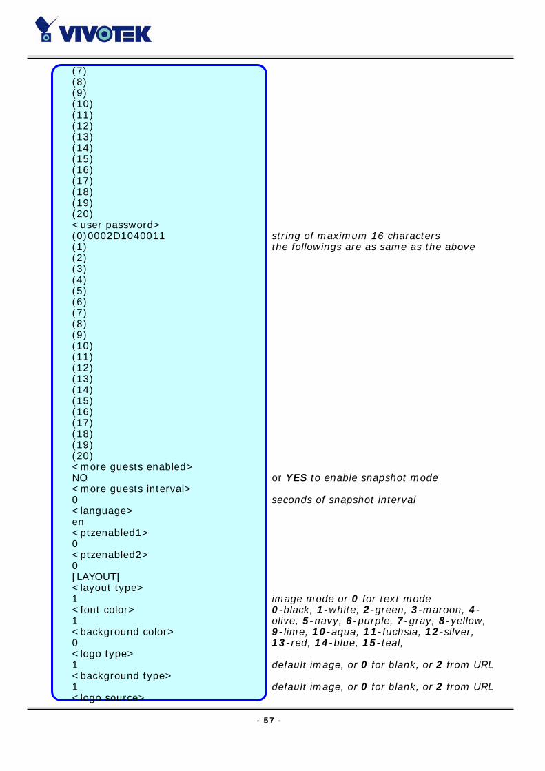
- 57 -
(7) (8) (9) (10) (11) (12) (13) (14) (15) (16) (17) (18) (19) (20) <user password> (0)0002D1040011 string of maximum 16 characters (1) the followings are as same as the above (2) (3) (4) (5) (6) (7) (8) (9) (10) (11) (12) (13) (14) (15) (16) (17) (18) (19) (20) <more guests enabled> NO or YES to enable snapshot mode <more guests interval> 0 seconds of snapshot interval <language> en <ptzenabled1> 0 <ptzenabled2> 0 [LAYOUT] <layout type> 1 image mode or 0 for text mode <font color> 0-black, 1-white, 2-green, 3-maroon, 4- 1 olive, 5-navy, 6-purple, 7-gray, 8-yellow, <background color> 9-lime, 10-aqua, 11-fuchsia, 12-silver, 0 13-red, 14-blue, 15-teal, <logo type> 1 default image, or 0 for blank, or 2 from URL <background type> 1 default image, or 0 for blank, or 2 from URL <logo source>

- 58 -
http:// URL of logo type 2, maximum 80 characters <background source> http:// URL of logo type 2, maximum 80 characters <logo link> http:// reference link of logo, max. 80 characters <button name> (0)Video1 used in text mode, max. 16 characters (1)Video2 used in text mode, max. 16 characters (2)Video3 used in text mode, max. 16 characters (3)Video4 used in text mode, max. 16 characters <com1 speedlink name> (0) string of maximum 8 characters (1) string of maximum 8 characters (2) string of maximum 8 characters (3) string of maximum 8 characters (4) string of maximum 8 characters <com2 speedlink name> (0) string of maximum 8 characters (1) string of maximum 8 characters (2) string of maximum 8 characters (3) string of maximum 8 characters (4) string of maximum 8 characters [NETWORK] <install enabled> YES reset IP whenever system boots or NO <ppp enabled> YES obsolete <ethernet address> 00-02-D1-04-00-11 read-only <host ip> 192.168.0.207 standard IP format <subnet mask> 255.255.255.0 standard IP format <gateway ip> 0.0.0.0 standard IP format <primary name server> 0.0.0.0 standard IP format <secondary name server> 0.0.0.0 standard IP format <ntp enabled> NO or YES <network timing server> IP address or domain name <smtp mail server> IP address or domain name <mail recipient address> string of maximum 80 characters <mail return address> Video Server string of maximum 80 characters <backup smtp mail server> IP address or domain name <backup mail recipient address> string of maximum 80 characters <local ftp port> 21 or 1024 ~ 65535 <ftp server> IP address or domain name

- 59 -
<ftp port> 21 or 1024 ~ 65535 <ftp username> string of maximum 16 characters <ftp password> string of maximum 16 characters
<ftp init path> string of maximum 40 characters <ftp passive> NO or YES <backup ftp server> IP address or domain name <backup ftp port> 21 or 1024 ~ 65535 <bacup ftp username> string of maximum 16 characters <backup ftp password> string of maximum 16 characters <backup ftp init path> string of maximum 40 characters <backup ftp passive> NO or YES <http server port> 80 or 1024 ~ 65535 <bandwidth limit> 0 or 64000, 128000, 256000, 512000,
768000, 1000000, 1500000, 2000000 [VIDEO] <default video> 1 or 2, 3, 4 <camera modulation> AUTO or MANUAL NTSC or PAL, indication only while AUTO <video is open> (0)YES or NO (1)YES or NO (2)YES or NO (3)YES or NO <video mapped to COM port> (0)0 (1)0 (2)0 (3)0 <video mapped to ID> (0)0 depending on the camera (1)0 depending on the camera (2)0 depending on the camera (3)0 depending on the camera <overlay timestamp> (0)NO or YES (1)NO or YES (2)NO or YES (3)NO or YES <caption text> (0) string of maximum 16 characters (1) string of maximum 16 characters (2) string of maximum 16 characters (3) string of maximum 16 characters
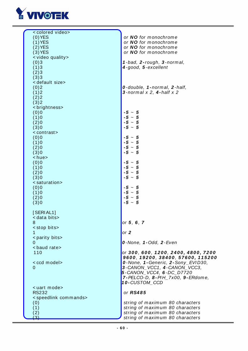
- 60 -
<colored video> (0)YES or NO for monochrome (1)YES or NO for monochrome (2)YES or NO for monochrome (3)YES or NO for monochrome <video quality> (0)3 1-bad, 2-rough, 3-normal, (1)3 4-good, 5-excellent (2)3 (3)3 <default size> (0)2 0-double, 1-normal, 2-half, (1)2 3-normal x 2, 4-half x 2 (2)2 (3)2 <brightness> (0)0 -5 ~ 5 (1)0 -5 ~ 5 (2)0 -5 ~ 5 (3)0 -5 ~ 5 <contrast> (0)0 -5 ~ 5 (1)0 -5 ~ 5 (2)0 -5 ~ 5 (3)0 -5 ~ 5 <hue> (0)0 -5 ~ 5 (1)0 -5 ~ 5 (2)0 -5 ~ 5 (3)0 -5 ~ 5 <saturation> (0)0 -5 ~ 5 (1)0 -5 ~ 5 (2)0 -5 ~ 5 (3)0 -5 ~ 5 [SERIAL1] <data bits> 8 or 5, 6, 7 <stop bits> 1 or 2 <parity bits> 0 0-None, 1-Odd, 2-Even <baud rate> 110 or 300, 600, 1200, 2400, 4800, 7200
9600, 19200, 38400, 57600, 115200 <ccd model> 0-None, 1-Generic, 2-Sony_EVID30, 0 3-CANON_VCC1, 4-CANON_VCC3, 5-CANON_VCC4, 6-DC_D7720 7-PELCO-D, 8-PIH_7x00, 9-ERdome, 10-CUSTOM_CCD
<uart mode> RS232 or RS485 <speedlink commands> (0) string of maximum 80 characters (1) string of maximum 80 characters (2) string of maximum 80 characters (3) string of maximum 80 characters

- 61 -
(4) string of maximum 80 characters <custom ccd commands> HOME string of maximum 80 characters UP string of maximum 80 characters DOWN string of maximum 80 characters LEFT string of maximum 80 characters RIGHT string of maximum 80 characters TELESCOPE string of maximum 80 characters WIDE string of maximum 80 characters NEAR string of maximum 80 characters FAR string of maximum 80 characters [SERIAL2] <data bits> 8 <stop bits> 1 <parity bits> 0 <baud rate> 0 <ccd model> 0 <uart mode> RS232 <speedlink commands> (0) string of maximum 80 characters (1) string of maximum 80 characters (2) string of maximum 80 characters (3) string of maximum 80 characters (4) string of maximum 80 characters <custom ccd commands> HOME string of maximum 80 characters UP string of maximum 80 characters DOWN string of maximum 80 characters LEFT string of maximum 80 characters RIGHT string of maximum 80 characters TELESCOPE string of maximum 80 characters WIDE string of maximum 80 characters NEAR string of maximum 80 characters FAR
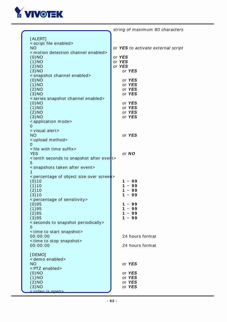
- 62 -
string of maximum 80 characters [ALERT] <script file enabled> NO or YES to activate external script <motion detection channel enabled> (0)NO or YES (1)NO or YES (2)NO or YES (3)NO or YES <snapshot channel enabled> (0)NO or YES (1)NO or YES (2)NO or YES (3)NO or YES <series snapshot channel enabled> (0)NO or YES (1)NO or YES (2)NO or YES (3)NO or YES <application mode> 0 <visual alert> NO or YES <upload method> 0 <file with time suffix> YES or NO <tenth seconds to snapshot after event> 5 <snapshots taken after event> 1 <percentage of object size over screen> (0)10 1 ~ 99 (1)10 1 ~ 99 (2)10 1 ~ 99 (3)10 1 ~ 99 <percentage of sensitivity> (0)95 1 ~ 99 (1)95 1 ~ 99 (2)95 1 ~ 99 (3)95 1 ~ 99 <seconds to snapshot periodically> 0 <time to start snapshot> 00:00:00 24 hours format <time to stop snapshot> 00:00:00 24 hours format [DEMO] <demo enabled> NO or YES <PTZ enabled> (0)NO or YES (1)NO or YES (2)NO or YES (3)NO or YES <video is open>

- 63 -
(0)NO or YES (1)NO or YES (2)NO or YES (3)NO or YES [SYSTEM ADDON] <NTP Update Interval> 3 0-Hourly, 1-Daily, 2-Weekly,
4-monthly
- 64 -
Telnet Commands
Video Server has a Telnet daemon for only administrators to access some seldom used
functions. Using any general terminal program to connect to Video Server will prompt
the user for a password. Username is not requested here since only administrators can
access the Telnet daemon. The password is as same as that used in web access. After
logging in, type "help" for the command list. If "debug" or "dinote" is not executed,
Telnet will disconnect automatically after being idle for 1 minute.
System core debugging General activities are recorded into SYSTEM.LOG continuously, but information about
abnormal status is not. To look deep into the core debugging information, administrators
may type the “debug” command. This will cause Video Server to start dumping the
detailed debugging information while the system is running. This is useful to examine if
any error has occurred when the system operates abnormally. The stored information
will be cleared automatically after the dump. Video Server will continue to dump new
messages unless the connection is broken. If Telnet is not connected, any messages will
be stored until administrators re-login.
Monitor changed status of digital inputs Typing "dinote" will make Video Server send the current status of all digital inputs. After
that Video Server will continuously monitor DI status and send messages only when the
state has changed. For example, after typing "dinote" the terminal will display
DI1=L
DI2=L
DI3=L
DI4=L
and if DI2 changes to H, terminal will display only
DI2=H
Stop information dumping Typing "stop" will cease dumping debug information and the digital input status.
Query status of digital inputs Typing "diquery" will display the status of all digital inputs once.
- 65 -
Set digital outputs To set digital output 1 to connect NO with COMMON, type "DO1=O".
To set digital output 1 to connect NC with COMMON, type "DO1=C".
To set digital output 2 to connect NO with COMMON, type "DO2=O".
To set digital output 2 to connect NC with COMMON, type "DO2=C".
Erase snapshots stored in Flash memory Typing "erase image" will clear all snapshots saved in Flash memory.
Erase logo and graphic buttons Typing "erase graph" will clear all images used on the homepage. If no new images are
uploaded, the system will switch to text mode and use default images instead.
Skip installation at next boot Typing "lock" will inform Video Server to fix current network settings. It need not wait for
installation during the next boot.
Reset network for new settings Typing "unlock" will make Video Server give up current settings and wait for installation.
Restore factory default settings Typing "clear" will make Video Server restore factory settings but not restart. To validate
new settings, type "reset" to make the system restart.
Reset system Typing "reset" will make Video Server perform a software reset.
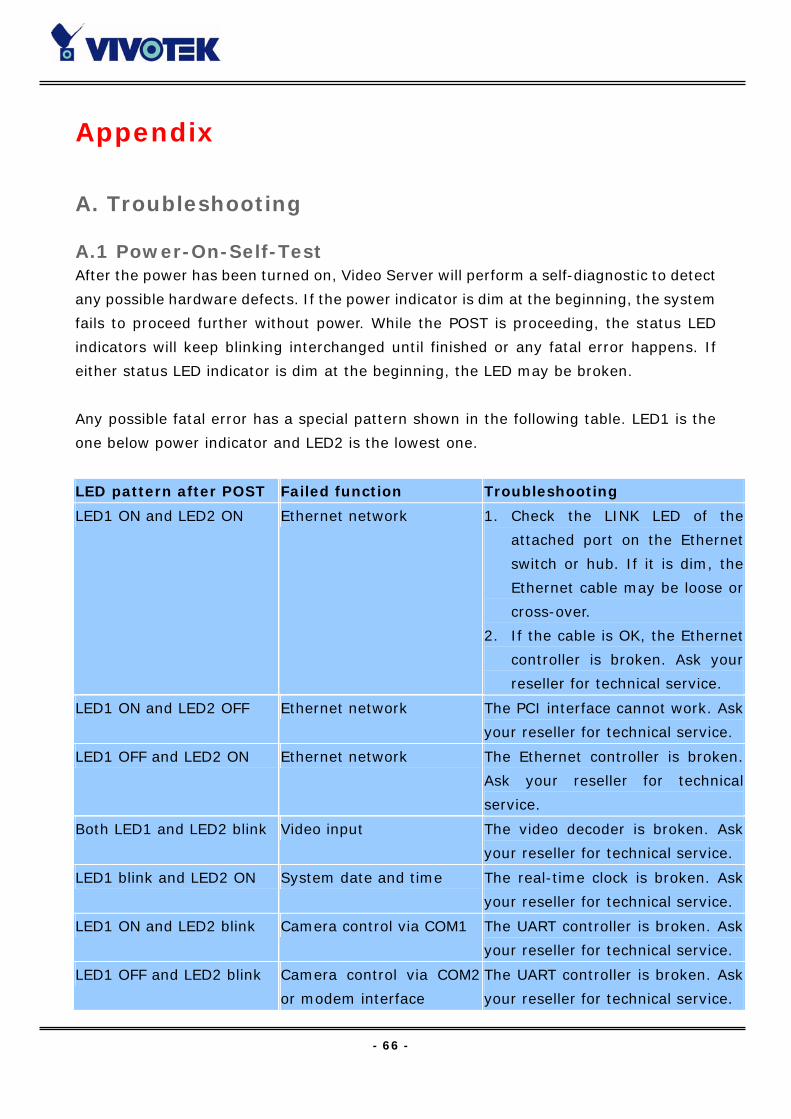
- 66 -
Appendix
A. Troubleshooting
A.1 Power-On-Self-Test After the power has been turned on, Video Server will perform a self-diagnostic to detect
any possible hardware defects. If the power indicator is dim at the beginning, the system
fails to proceed further without power. While the POST is proceeding, the status LED
indicators will keep blinking interchanged until finished or any fatal error happens. If
either status LED indicator is dim at the beginning, the LED may be broken.
Any possible fatal error has a special pattern shown in the following table. LED1 is the
one below power indicator and LED2 is the lowest one.
LED pattern after POST Failed function Troubleshooting
LED1 ON and LED2 ON Ethernet network 1. Check the LINK LED of the
attached port on the Ethernet
switch or hub. If it is dim, the
Ethernet cable may be loose or
cross-over.
2. If the cable is OK, the Ethernet
controller is broken. Ask your
reseller for technical service.
LED1 ON and LED2 OFF Ethernet network The PCI interface cannot work. Ask
your reseller for technical service.
LED1 OFF and LED2 ON Ethernet network The Ethernet controller is broken.
Ask your reseller for technical
service.
Both LED1 and LED2 blink Video input The video decoder is broken. Ask
your reseller for technical service.
LED1 blink and LED2 ON System date and time The real-time clock is broken. Ask
your reseller for technical service.
LED1 ON and LED2 blink Camera control via COM1 The UART controller is broken. Ask
your reseller for technical service.
LED1 OFF and LED2 blink Camera control via COM2
or modem interface
The UART controller is broken. Ask
your reseller for technical service.
- 67 -
A.2 System recovery Video Server provides two auxiliary buttons located on the center of the front panel for
system recovery by hardware. The buttons can be used to perform either level of system
recovery. “Reset” will force the system restart at any point; “Restore” will restore the
default settings from factory and then force the system restart to work at the initial state.
Consequently “restore” is generally used to completely recover the system from serious
fault in configuration.
RESET Click on the “RESET” button once. The system will perform the system diagnosis and the
software installation may be necessary if the IP address is not fixed. This procedure is as
same as removing the power and attaching it again.
RESTORE When the system seems to respond or operate slowly after changing some settings and
administrators hardly enter the configuration to change back the original settings,
administrators can perform the “restore” procedure. It is as same as the “factory
default” link on the configuration page. To restore the factory default settings, click on
the “RESET” button once and then press the “CLEAR” button firmly. The system
diagnosis will start right away and the “status” LED will be turn on after system diagnosis
to indicate the “CLEAR” button is pressed. The second system diagnosis will start again
in several seconds after erasing the system parameters. Administrators can release the
“CLEAR” button now and perform the installation for the initialized system.
To reduce the system failure caused by operation error, always read the related
sections in this user’s manual to prevent from unexpected error caused by wild-guess
configuration.
- 68 -
B. Frequently Asked Questions
Q Why can’t I see the Video Server in the installer after reboot?
A The installer is only used to install the IP address of Video Server. If the IP address is
fixed by checking the option in the installer, the Video Server will no longer appear in the
installer.
Q Why can’t I connect the Video Server after reboot?
A If the IP address is not fixed, Video Server will always wait for installing command for
a valid IP address. That means the previous IP address will not be used if the option in
the installer is not checked; or the option in the network configuration is not cleared. The
benefit of waiting for a valid IP address by default is that administrators can find the
Video Server in the installer to prevent IP conflict. As long as the IP address is confirmed,
it is suggested to fix the IP address to make Video Server automatically start up
whenever regaining power.
Q What if I forget my password?
A Every access to Video Server needs authentication. If you are not a permitted user,
you may view the images or control the camera as long as the demo account is opened.
The demo account user may use username as “demo” without any password to access
limited features. If you are one of the managed users, you have to ask the administrators
for the password. If you are the administrator, there is no way to recover the root
password. The only way to regain access to Video Server is to restore the factory settings
and reinstall it.
Q Why can I not watch video from Video Server after it is authenticated?
A There are many possible scenarios regarding this problem,
1. If you have just installed Video Server and are unable to watch the video, check if the
video input is enabled and the video modulation in Configuration page.
2. If Video Server is well installed and you are accessing Video Server for the first time
using Internet Explorer, adjust the security level of Internet Explorer to allow installation
of the plug-in.
3. If the problem still exists after adjusting, the current users may be over the system
allows.
4. In case that you use demo account, the video may be protected from the public by the
administrator.
- 69 -
Q How can I use a name instead of the IP address to connect Video Server?
A To allow users to connect to Video Server through an easily memorized name, the
administrators must first configure the name server in his network. Here is an example:
the administrator installs the Video Server with a reserved IP address and assigns it with
a name in the domain name service, then users can connect to Video Server by typing a
name instead of IP address. If there is DHCP service in the network, the IP address must
be excluded in the DHCP service to prevent from IP conflict.
Q What is the plug-in for?
A The plug-in provided by Video Server is used to display motion pictures on Internet
Explorer that does not support server push technology. If your system does not allow
installation of any plug-in software, the security level of web browser may need to be
lowered. It is recommended that you consult your network supervisor in your office
regarding the adjustment of the security level.
Q Why is the timestamp different from the system time of my PC or notebook?
A The timestamp is based on the system time of Video Server. It is maintained by a
real-time clock inside and automatically synchronizes with the time server if Video
Server is connected to the Internet and the function is enabled. Differences of several
hours may result from the time zone setting.
Q Why does the image not refresh regularly?
A In a modem environment, it is because the bandwidth of PPP connection is far less
than Ethernet. If the difference of the timestamp is not stable, adjust the UART FIFO
lower in both receiving and transmitting from modem property in the control panel.
While in Ethernet, it may be due to time taken in storing snapshots into memory upon
events occurring.
Q How many users are allowed to watch Video Server at the same time?
A To achieve the best effect, Video Server will allow twenty users to connect at the same
time. Excess users can get an auto-refreshed still image in homepage instead. It is
recommended to build another web server to host a large quantity of users by retrieving
images from Video Server periodically.
Q How fast is the video rate of Video Server?
A The JPEG codec can process 30 frames per second internally. However the total
performance is subject to many coefficients as follows,
1. network throughput,
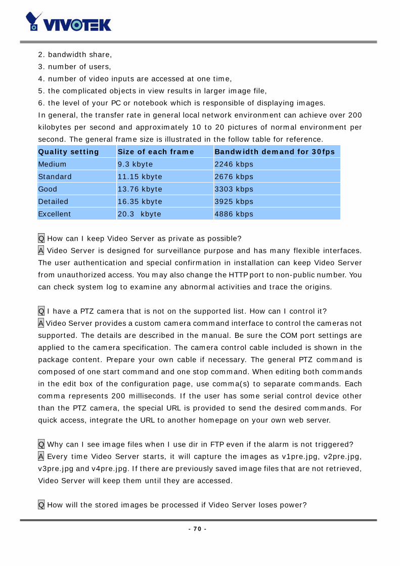
- 70 -
2. bandwidth share,
3. number of users,
4. number of video inputs are accessed at one time,
5. the complicated objects in view results in larger image file,
6. the level of your PC or notebook which is responsible of displaying images.
In general, the transfer rate in general local network environment can achieve over 200
kilobytes per second and approximately 10 to 20 pictures of normal environment per
second. The general frame size is illustrated in the follow table for reference.
Quality setting Size of each frame Bandwidth demand for 30fps
Medium 9.3 kbyte 2246 kbps
Standard 11.15 kbyte 2676 kbps
Good 13.76 kbyte 3303 kbps
Detailed 16.35 kbyte 3925 kbps
Excellent 20.3 kbyte 4886 kbps
Q How can I keep Video Server as private as possible?
A Video Server is designed for surveillance purpose and has many flexible interfaces.
The user authentication and special confirmation in installation can keep Video Server
from unauthorized access. You may also change the HTTP port to non-public number. You
can check system log to examine any abnormal activities and trace the origins.
Q I have a PTZ camera that is not on the supported list. How can I control it?
A Video Server provides a custom camera command interface to control the cameras not
supported. The details are described in the manual. Be sure the COM port settings are
applied to the camera specification. The camera control cable included is shown in the
package content. Prepare your own cable if necessary. The general PTZ command is
composed of one start command and one stop command. When editing both commands
in the edit box of the configuration page, use comma(s) to separate commands. Each
comma represents 200 milliseconds. If the user has some serial control device other
than the PTZ camera, the special URL is provided to send the desired commands. For
quick access, integrate the URL to another homepage on your own web server.
Q Why can I see image files when I use dir in FTP even if the alarm is not triggered?
A Every time Video Server starts, it will capture the images as v1pre.jpg, v2pre.jpg,
v3pre.jpg and v4pre.jpg. If there are previously saved image files that are not retrieved,
Video Server will keep them until they are accessed.
Q How will the stored images be processed if Video Server loses power?
- 71 -
A If user has defined the snapshot interval, Video Server will capture images of four
video inputs periodically as pre-alarm stage. Once the pre-defined condition is match,
the pre-alarm images will be kept and the current images will be saved. The subsequent
images will be stored as post-alarm stage. User may retrieve these files either by
downloading via FTP or direct Video Server send them in e-mails. That means after
monitoring conditions are met, Video Server will keep these image files until user
retrieval even if power is lost.
Q If I set Video Server to send e-mails of images whenever the conditions are met, will
my e-mail account overflow?
A It is recommended to use transient state rather than steady state. For instance, use
‘Rising’ and ‘Falling’ rather than ‘High’ and ‘Low’ to let the condition be triggered only
when state is changed.
Q I have already set the video inputs to different quality but I still see the old quality
setting when I choose Video All.
A Video All is a special feature to be used for quick checking for four cameras at the same
time. Internally four images of video inputs are compressed with the same settings
based on the first video source.
Q I try to connect my black-and-white and color cameras with Video Server but the
image is not good.
A Although Video Server allows users to choose color or black-and-white images for each
camera, hybrid camera types may increase video processing time and reduce system
performance. While connecting multiple cameras, the same modulation type and color
format are recommended.
Q The image is not clear enough. Is anything broken?
A The lens can be fine adjusted by rotating the outer ring. Please rotate it clockwise or
counter-clockwise to focus near or far.
- 72 -
C. Upgrade System Firmware
Customers can frequently check the appropriate product folder on our web site to
download the latest firmware. Only administrators can upgrade the system firmware of
Video Server.
Easy way via Upgrade Wizard Run the Upgrade Wizard included in the product CDROM and proceed by the prompts.
Refer to the user's guide of Upgrade Wizard for details.
Alternative via FTP 1. Decompress the compressed file in a local folder. A file named FLASH.BIN should
appear.
2. Use the FTP program and change the working directory to the local folder where
FLASH.BIN exists.
3. Connect to Video Server with user name as “root” and password.
4. Use the PUT command to upload FLASH.BIN to Video Server. The file size is near 1.5
mega bytes. It will take approximately 2 seconds in a local network, 2 minutes by null
modem connection or 6 minutes by modem, but still subject to user's network.
5. After upload is complete, close the connection.
6. If the received FLASH.BIN is checked without error, Video Server will update the
software in Flash memory and restart automatically. When Video Server starts writing
firmware, both status LED indicators will stay on until system restarts. It takes about 30
to 40 seconds. User must keep the power stable during the update process. After the
system restarts, Video Server may need installation depending on whether the “Reset
network at next boot” option is enabled or not. After Video Server boots up, reload the
web page in the browser.
If power fails during the software upgrade, the program in the memory of Video
Server may be destroyed permanently. If Video Server cannot restart properly, ask the
dealer for technical service.

- 73 -
D. URL Commands of Video Server
For some customers who already have their own web site or web control application,
Video Server can be easily integrated through convenient URL. This section lists the
commands in URL format corresponding to the basic functions of Video Server. Some
RFC standards related to HTML may be a good reference for implementation of the
customized homepage.
Page URL The configuration page has a frame layout including option list frame and an option page
frame. Referenced URL except for the configuration page directs to option page frame
only. Some pages, like image quality setting and preset setting, are opened in new
windows for preview.
These URLs can be accessed only by administrators.
Homepage name Referenced URL
configuration page /setup/config.html
system option /setup/system.html
security option /setup/security.html
network option /setup/network.html
video option /setup/video.html
image quality option /setup/image.html
camera control 1 /setup/serial1.html
camera control 2 / modem /setup/serial2.html
preset PTZ camera /setup/preset.html
custom command setting /setup/cuscom.html
custom camera setting /setup/custom.html
application option /setup/app.html
motion detection setting /setup/motion.html
view snapshots /setup/snap.html
demo option /setup/demo.html
homepage layout option /setup/layout.html
system log /setup/logfile.html
system parameters /setup/parafile.html
set factory default /setup/factory.html
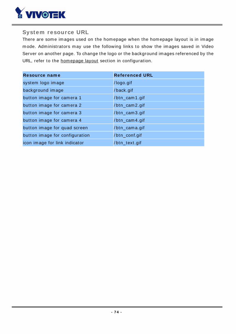
- 74 -
System resource URL There are some images used on the homepage when the homepage layout is in image
mode. Administrators may use the following links to show the images saved in Video
Server on another page. To change the logo or the background images referenced by the
URL, refer to the homepage layout section in configuration.
Resource name Referenced URL
system logo image /logo.gif
background image /back.gif
button image for camera 1 /btn_cam1.gif
button image for camera 2 /btn_cam2.gif
button image for camera 3 /btn_cam3.gif
button image for camera 4 /btn_cam4.gif
button image for quad screen /btn_cama.gif
button image for configuration /btn_conf.gif
icon image for link indicator /btn_text.gif

- 75 -
General format of command URL Every configuration can be set through URL with POST method by administrators only.
<general format>
URL[?[name=value][&name=value]……]
<method>
POST
<authorized user>
root
System configuration URL URL: /cgi-bin/system.cgi
NAME VALUE DESCRIPTION
host <text string shorter than 15
characters>
system name
keep keep date and time unchanged
auto use NTP server to synchronize
method
manu directly adjust date and time
date <yy/mm/dd> year, month and date separated by
slash
time <hh:mm:ss> hour, minute and second separated
by colon
ntp <domain name or IP address> NTP server
zone GMT±<n>:00 time zone, n ranged from 0 to 12
updateInterval 0-Hourly,1-Daily,2-Weekly
4-monthly
video server will synch with NTP
server periodically
Security configuration URL URL: /cgi-bin/security.cgi
NAME VALUE DESCRIPTION
rootpass <text string shorter than 15
characters>
change root password
username <text string shorter than 15
characters>
add new user
userpass <text string shorter than 15
characters>
new user's password
v1allowed <not required> allow user to view video1
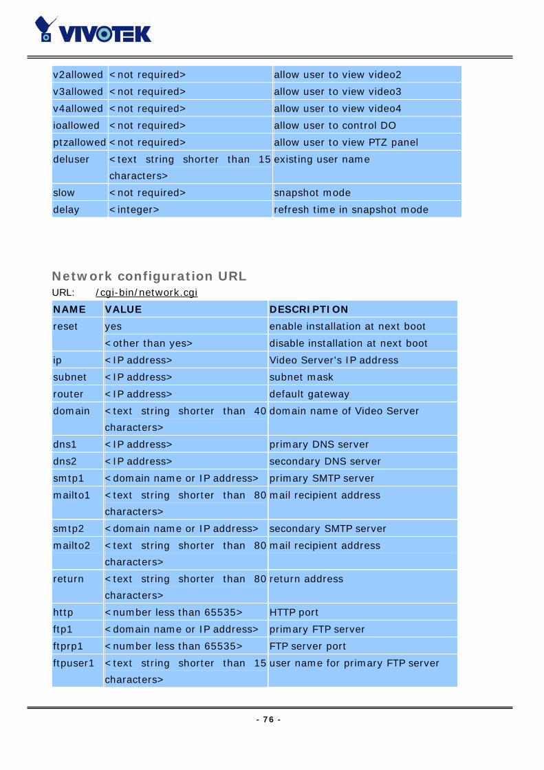
- 76 -
v2allowed <not required> allow user to view video2
v3allowed <not required> allow user to view video3
v4allowed <not required> allow user to view video4
ioallowed <not required> allow user to control DO
ptzallowed <not required> allow user to view PTZ panel
deluser <text string shorter than 15
characters>
existing user name
slow <not required> snapshot mode
delay <integer> refresh time in snapshot mode
Network configuration URL URL: /cgi-bin/network.cgi
NAME VALUE DESCRIPTION
yes enable installation at next boot reset
<other than yes> disable installation at next boot
ip <IP address> Video Server's IP address
subnet <IP address> subnet mask
router <IP address> default gateway
domain <text string shorter than 40
characters>
domain name of Video Server
dns1 <IP address> primary DNS server
dns2 <IP address> secondary DNS server
smtp1 <domain name or IP address> primary SMTP server
mailto1 <text string shorter than 80
characters>
mail recipient address
smtp2 <domain name or IP address> secondary SMTP server
mailto2 <text string shorter than 80
characters>
mail recipient address
return <text string shorter than 80
characters>
return address
http <number less than 65535> HTTP port
ftp1 <domain name or IP address> primary FTP server
ftprp1 <number less than 65535> FTP server port
ftpuser1 <text string shorter than 15
characters>
user name for primary FTP server

- 77 -
ftppass1 <text string shorter than 15
characters>
password for primary FTP server
ftpfolder1 <text string shorter than 40
characters>
upload folder in primary FTP server
ftp2 <domain name or IP address> secondary FTP server
ftprp2 <number less than 65535> secondary FTP server port
ftpuser2 <text string shorter than 15
characters>
user name for secondary FTP server
ftppass2 <text string shorter than 15
characters>
password for secondary FTP server
ftpfolder2 <text string shorter than 40
characters>
upload folder in secondary FTP server
Not limited use full network bandwidth
64Kbits/second use only 64Kbps of bandwidth
128Kbits/second use only 128Kbps of bandwidth
256Kbits/second use only 256Kbps of bandwidth
512Kbits/second use only 512Kbps of bandwidth
768Kbits/second use only 768Kbps of bandwidth
1Mbits/second use only 1Mbps of bandwidth
1.5Mbits/second use only 1.5Mbps of bandwidth
limit
2Mbits/second use only 2Mbps of bandwidth
Video configuration URL URL: /cgi-bin/video.cgi
NAME VALUE DESCRIPTION
enable1 <not required> enable video channel 1
enable2 <not required> enable video channel 2
enable3 <not required> enable video channel 3
enable4 <not required> enable video channel 4
Auto let Video Server detect video
modulation
NTSC set directly to NTSC type
mode
<other than above> set directly to PAL type
source <1, 2, 3, 4 or All> default video channel
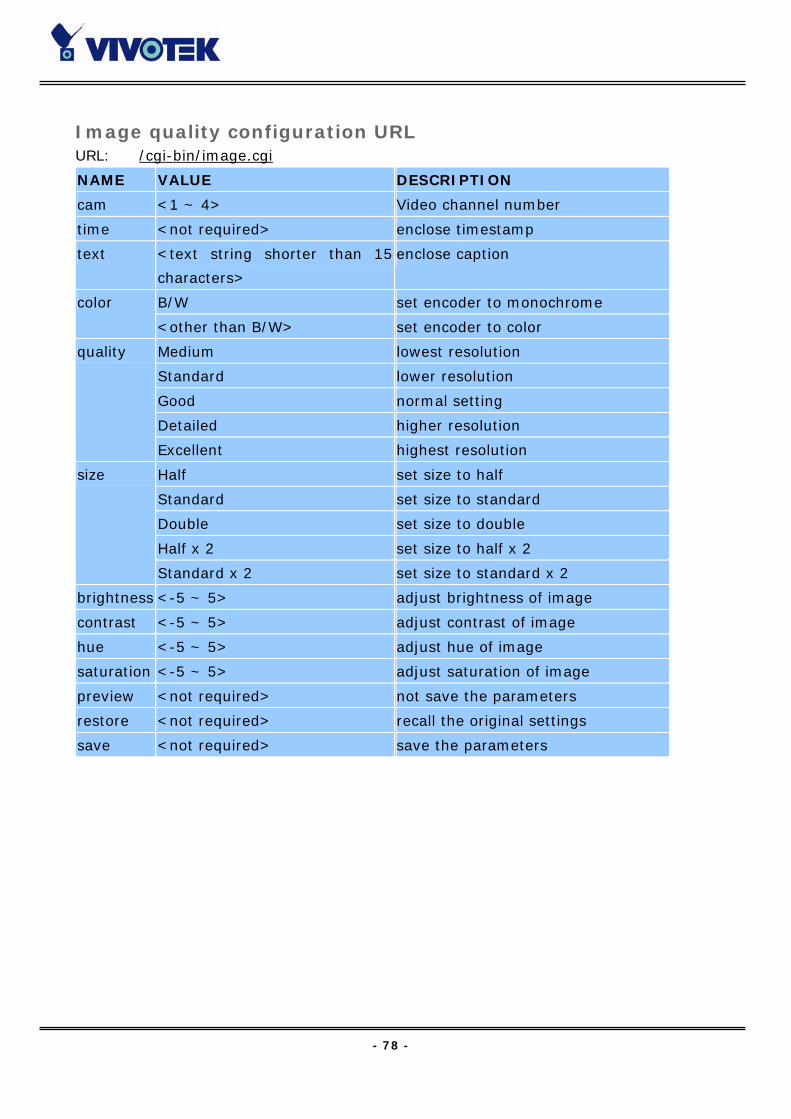
- 78 -
Image quality configuration URL URL: /cgi-bin/image.cgi
NAME VALUE DESCRIPTION
cam <1 ~ 4> Video channel number
time <not required> enclose timestamp
text <text string shorter than 15
characters>
enclose caption
B/W set encoder to monochrome color
<other than B/W> set encoder to color
Medium lowest resolution
Standard lower resolution
Good normal setting
Detailed higher resolution
quality
Excellent highest resolution
Half set size to half
Standard set size to standard
Double set size to double
Half x 2 set size to half x 2
size
Standard x 2 set size to standard x 2
brightness <-5 ~ 5> adjust brightness of image
contrast <-5 ~ 5> adjust contrast of image
hue <-5 ~ 5> adjust hue of image
saturation <-5 ~ 5> adjust saturation of image
preview <not required> not save the parameters
restore <not required> recall the original settings
save <not required> save the parameters

- 79 -
COM 1 configuration URL URL: /cgi-bin/serial1.cgi
NAME VALUE DESCRIPTION
RS232 switch COM1 to RS232 interface
<other than RS232> switch COM1 to RS485
generic accept generic CGI commands detect
none no drivers
Sony VISCA
Canon VCC1
Canon VCC3
Canon VCC4
DynaDome/SmartDOME
Pelco D protocol
Lilin PIH-7x00
Ernitec
driver
Custom Camera third party PTZ camera
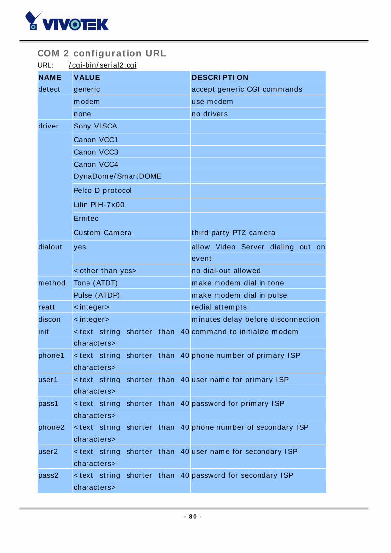
- 80 -
COM 2 configuration URL URL: /cgi-bin/serial2.cgi
NAME VALUE DESCRIPTION
generic accept generic CGI commands
modem use modem
detect
none no drivers
Sony VISCA
Canon VCC1
Canon VCC3
Canon VCC4
DynaDome/SmartDOME
Pelco D protocol
Lilin PIH-7x00
Ernitec
driver
Custom Camera third party PTZ camera
yes allow Video Server dialing out on
event
dialout
<other than yes> no dial-out allowed
Tone (ATDT) make modem dial in tone method
Pulse (ATDP) make modem dial in pulse
reatt <integer> redial attempts
discon <integer> minutes delay before disconnection
init <text string shorter than 40
characters>
command to initialize modem
phone1 <text string shorter than 40
characters>
phone number of primary ISP
user1 <text string shorter than 40
characters>
user name for primary ISP
pass1 <text string shorter than 40
characters>
password for primary ISP
phone2 <text string shorter than 40
characters>
phone number of secondary ISP
user2 <text string shorter than 40
characters>
user name for secondary ISP
pass2 <text string shorter than 40
characters>
password for secondary ISP
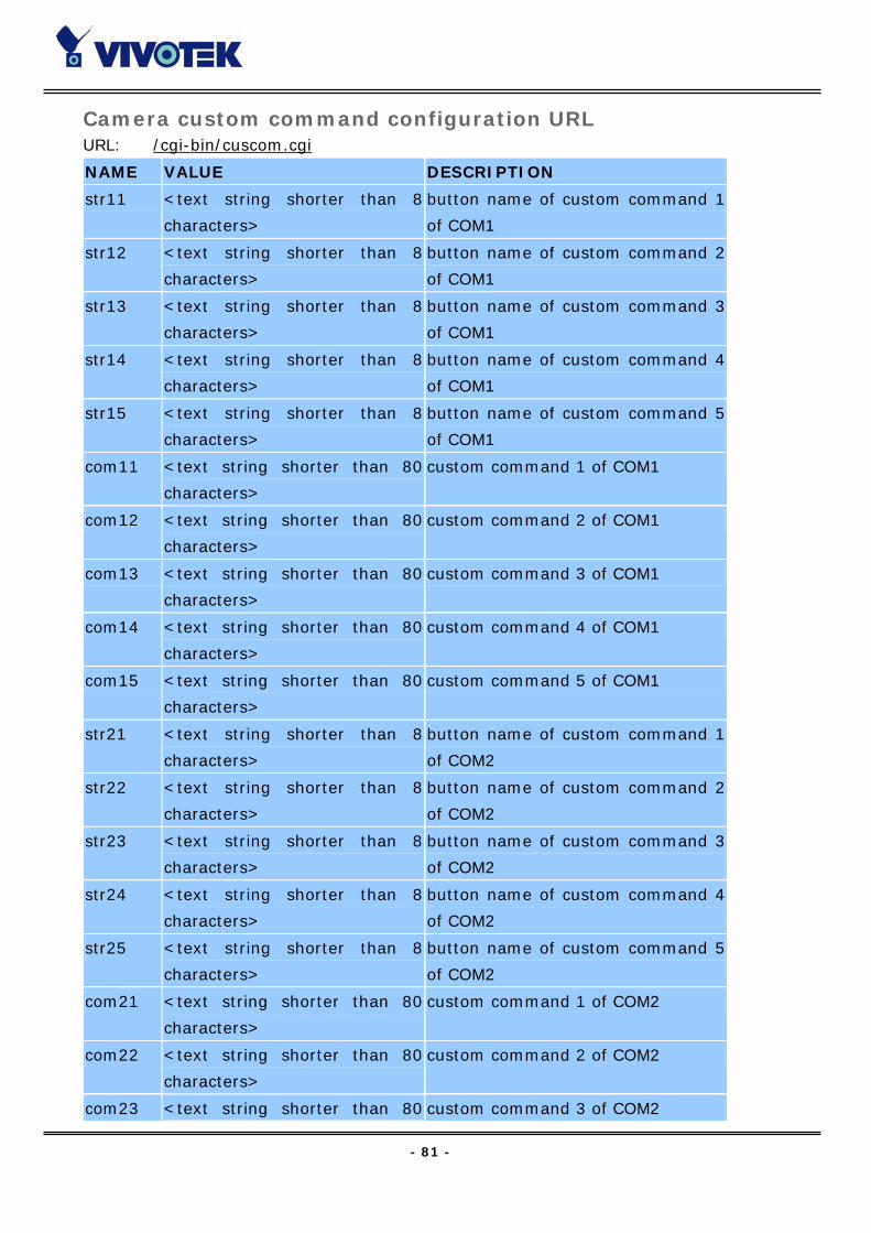
- 81 -
Camera custom command configuration URL URL: /cgi-bin/cuscom.cgi
NAME VALUE DESCRIPTION
str11 <text string shorter than 8
characters>
button name of custom command 1
of COM1
str12 <text string shorter than 8
characters>
button name of custom command 2
of COM1
str13 <text string shorter than 8
characters>
button name of custom command 3
of COM1
str14 <text string shorter than 8
characters>
button name of custom command 4
of COM1
str15 <text string shorter than 8
characters>
button name of custom command 5
of COM1
com11 <text string shorter than 80
characters>
custom command 1 of COM1
com12 <text string shorter than 80
characters>
custom command 2 of COM1
com13 <text string shorter than 80
characters>
custom command 3 of COM1
com14 <text string shorter than 80
characters>
custom command 4 of COM1
com15 <text string shorter than 80
characters>
custom command 5 of COM1
str21 <text string shorter than 8
characters>
button name of custom command 1
of COM2
str22 <text string shorter than 8
characters>
button name of custom command 2
of COM2
str23 <text string shorter than 8
characters>
button name of custom command 3
of COM2
str24 <text string shorter than 8
characters>
button name of custom command 4
of COM2
str25 <text string shorter than 8
characters>
button name of custom command 5
of COM2
com21 <text string shorter than 80
characters>
custom command 1 of COM2
com22 <text string shorter than 80
characters>
custom command 2 of COM2
com23 <text string shorter than 80 custom command 3 of COM2
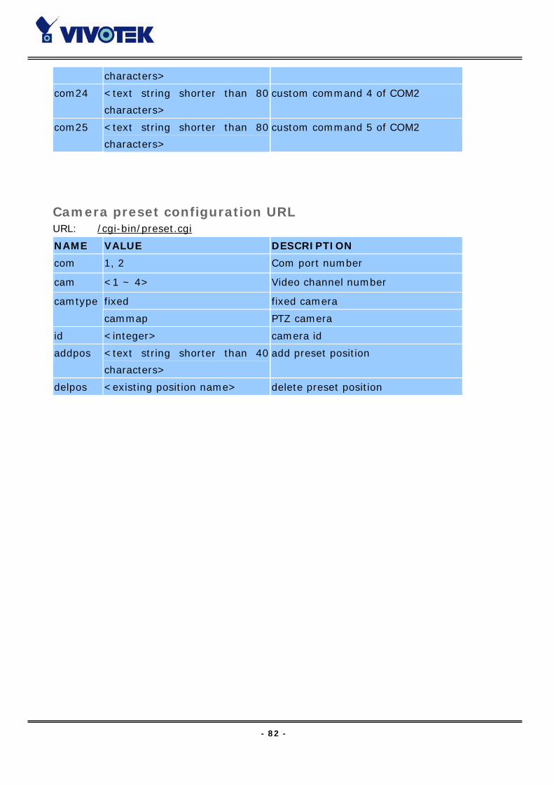
- 82 -
characters>
com24 <text string shorter than 80
characters>
custom command 4 of COM2
com25 <text string shorter than 80
characters>
custom command 5 of COM2
Camera preset configuration URL URL: /cgi-bin/preset.cgi
NAME VALUE DESCRIPTION
com 1, 2 Com port number
cam <1 ~ 4> Video channel number
fixed fixed camera camtype
cammap PTZ camera
id <integer> camera id
addpos <text string shorter than 40
characters>
add preset position
delpos <existing position name> delete preset position

- 83 -
Custom camera configuration URL URL: /cgi-bin/custom.cgi
NAME VALUE DESCRIPTION
baud1 <integer> set baud rate of COM1
data1 <integer> set data bits of COM1
1 set 1 stop bit of COM1 stop1
2 <other than 1> set 2 stop bits of COM1
None set parity check of COM1 to none
Odd set parity check of COM1 to odd
parity1
Even set parity check of COM1 to even
up1 <text string shorter than 80
characters>
tilt up command string of COM1
down1 <text string shorter than 80
characters>
tilt down command string of COM1
left1 <text string shorter than 80
characters>
pan left command string of COM1
right1 <text string shorter than 80
characters>
pan right command string of COM1
home1 <text string shorter than 80
characters>
home command string of COM1
tele1 <text string shorter than 80
characters>
zoom in command string of COM1
wide1 <text string shorter than 80
characters>
zoom out command string of COM1
baud2 <integer> set baud rate of COM2
data2 <integer> set data bits of COM2
1 set 1 stop bit of COM2 stop2
2 <other than 1> set 2 stop bits of COM2
None set parity check of COM2 to none
Odd set parity check of COM2 to odd
parity2
Even set parity check of COM2 to even
up2 <text string shorter than 80
characters>
tilt up command string of COM2
down2 <text string shorter than 80
characters>
tilt down command string of COM2
left2 <text string shorter than 80
characters>
pan left command string of COM2
right2 <text string shorter than 80 pan right command string of COM2

- 84 -
characters>
home2 <text string shorter than 80
characters>
home command string of COM2
tele2 <text string shorter than 80
characters>
zoom in command string of COM2
wide2 <text string shorter than 80
characters>
zoom out command string of COM2
Application configuration URL URL: /cgi-bin/app.cgi
NAME VALUE DESCRIPTION
sun <not required> set Sunday in weekly schedule
mon <not required> set Monday in weekly schedule
tue <not required> set Tueday in weekly schedule
wed <not required> set Wednesday in weekly schedule
thu <not required> set Thursday in weekly schedule
fri <not required> set Friday in weekly schedule
sat <not required> set Saturday in weekly schedule
sbegin <hh:mm:ss> time to start in weekly schedule
send <hh:mm:ss> time to stop in weekly schedule
inv <not required> set inverse mode in weekly schedule
enfile <not required> enable script file
emode <not required> event operation
showalert <not required> show alert in image
mdch1 <not required> enable motion detection on video 1
mdch2 <not required> enable motion detection on video 2
mdch3 <not required> enable motion detection on video 3
mdch4 <not required> enable motion detection on video 4
di1 High, Low, Rising, Falling or
Disable
DI1 condition
di2 High, Low, Rising, Falling or
Disable
DI2 condition
di3 High, Low, Rising, Falling or
Disable
DI3 condition
di4 High, Low, Rising, Falling or
Disable
DI4 condition
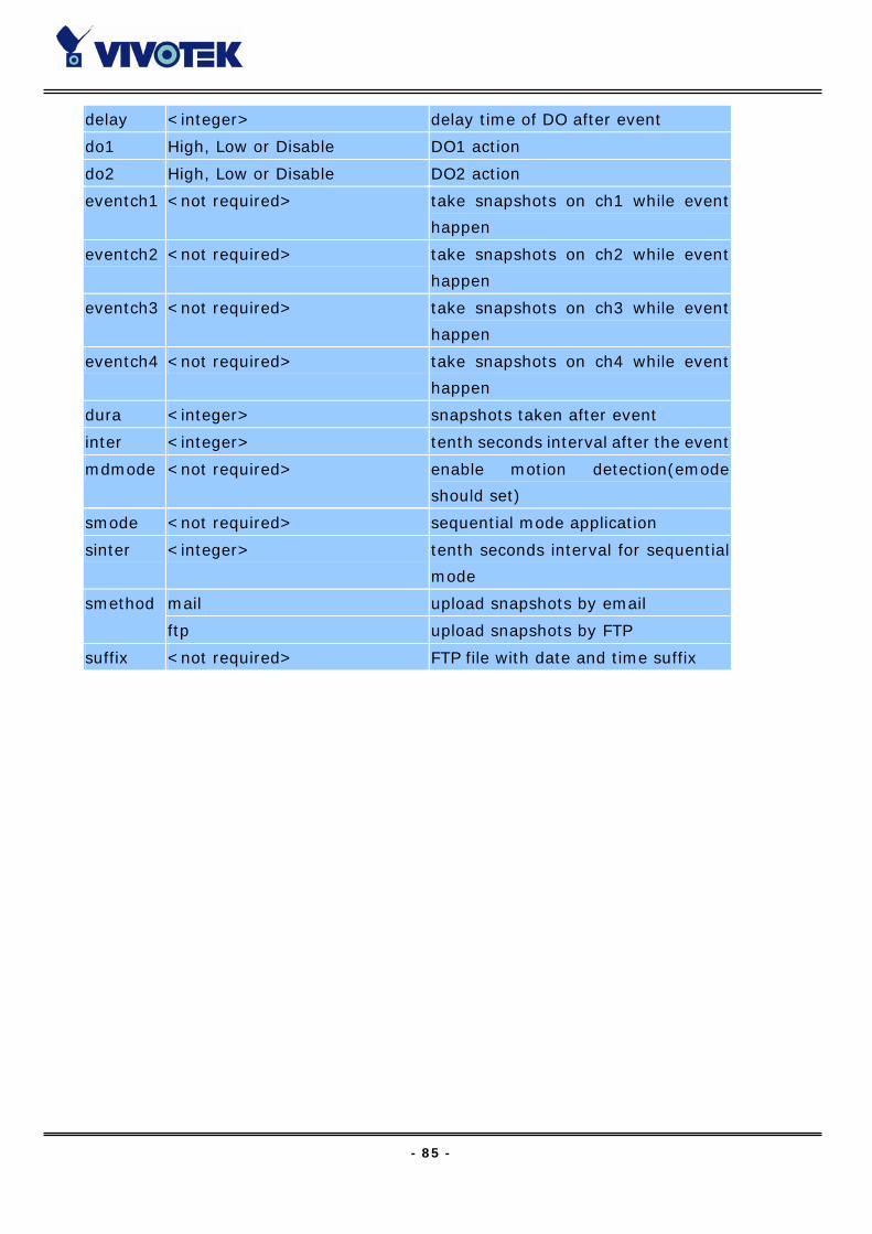
- 85 -
delay <integer> delay time of DO after event
do1 High, Low or Disable DO1 action
do2 High, Low or Disable DO2 action
eventch1 <not required> take snapshots on ch1 while event
happen
eventch2 <not required> take snapshots on ch2 while event
happen
eventch3 <not required> take snapshots on ch3 while event
happen
eventch4 <not required> take snapshots on ch4 while event
happen
dura <integer> snapshots taken after event
inter <integer> tenth seconds interval after the event
mdmode <not required> enable motion detection(emode
should set)
smode <not required> sequential mode application
sinter <integer> tenth seconds interval for sequential
mode
mail upload snapshots by email smethod
ftp upload snapshots by FTP
suffix <not required> FTP file with date and time suffix
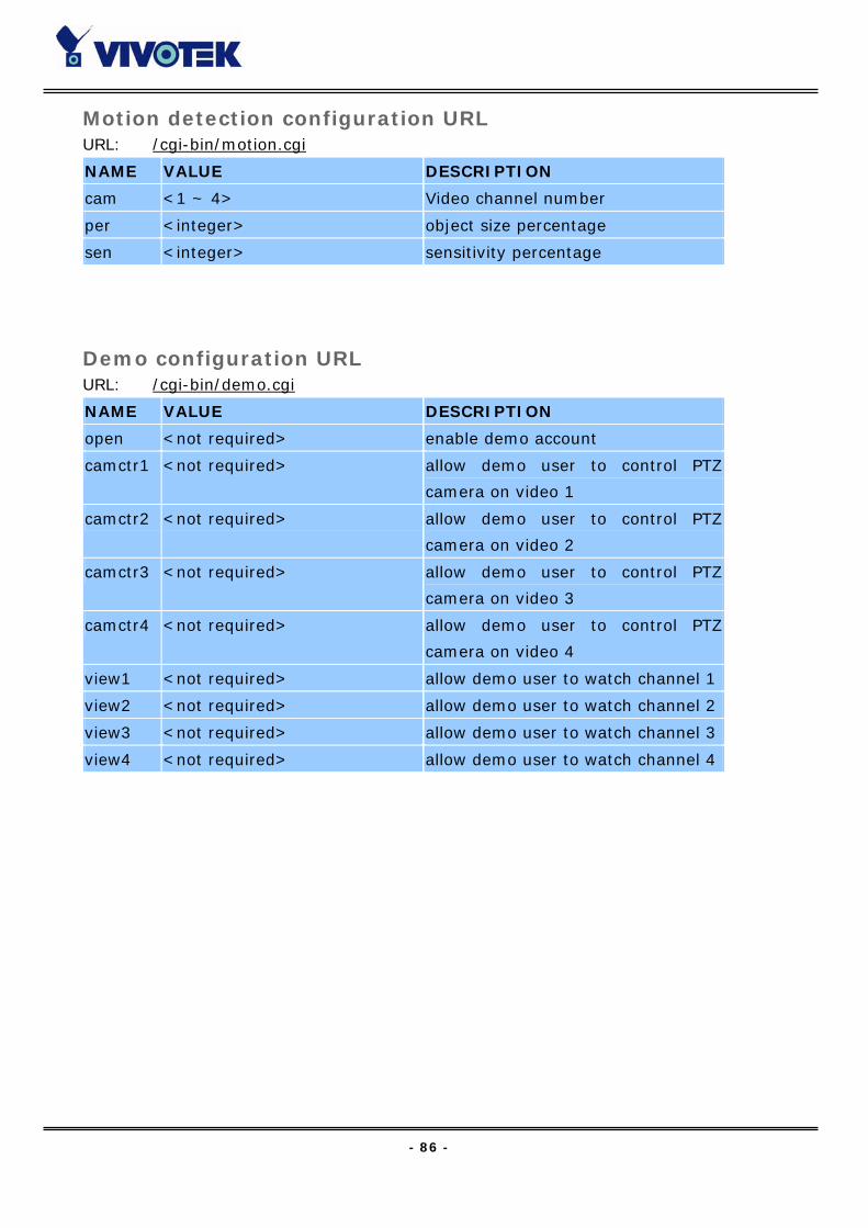
- 86 -
Motion detection configuration URL URL: /cgi-bin/motion.cgi
NAME VALUE DESCRIPTION
cam <1 ~ 4> Video channel number
per <integer> object size percentage
sen <integer> sensitivity percentage
Demo configuration URL URL: /cgi-bin/demo.cgi
NAME VALUE DESCRIPTION
open <not required> enable demo account
camctr1 <not required> allow demo user to control PTZ
camera on video 1
camctr2 <not required> allow demo user to control PTZ
camera on video 2
camctr3 <not required> allow demo user to control PTZ
camera on video 3
camctr4 <not required> allow demo user to control PTZ
camera on video 4
view1 <not required> allow demo user to watch channel 1
view2 <not required> allow demo user to watch channel 2
view3 <not required> allow demo user to watch channel 3
view4 <not required> allow demo user to watch channel 4

- 87 -
Homepage layout configuration URL URL: /cgi-bin/layout.cgi
NAME VALUE DESCRIPTION
blank hide logo
def use default logo
cuslogo
url use image from URL
logourl <text string shorter than 80
characters>
URL of image for logo
linkurl <text string shorter than 80
characters>
URL to link when clicking on logo
blank hide background image
def use default background
cusback
url use image from URL
backurl <text string shorter than 80
characters>
URL of image for background
fcolor <0 ~ 15> color index for font
bcolor <0 ~ 15> color index for background
image display homepage in image mode dismode
text display homepage in text mode
strl <text string shorter than 40
characters>
text for channel 1 in text mode
str2 <text string shorter than 40
characters>
text for channel 2 in text mode
str3 <text string shorter than 40
characters>
text for channel 3 in text mode
str4 <text string shorter than 40
characters>
text for channel 4 in text mode
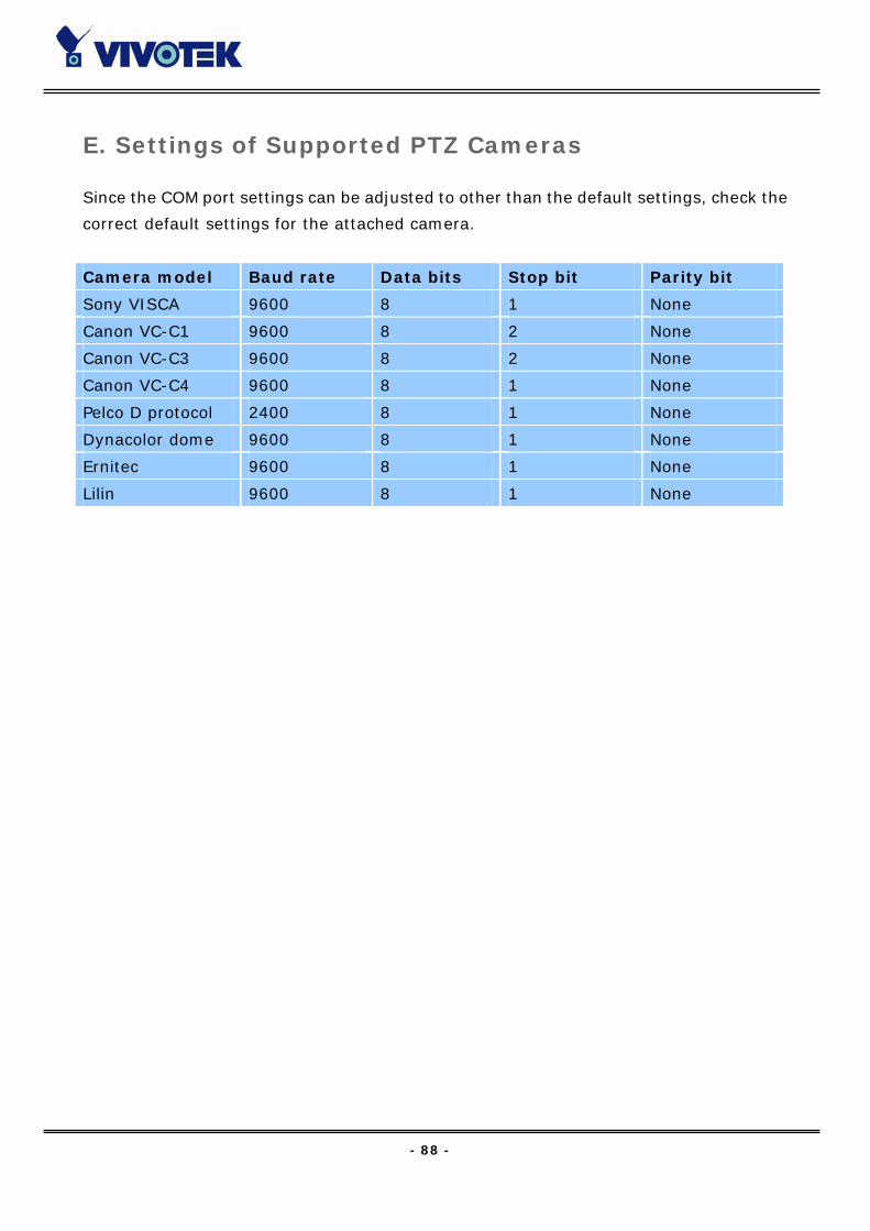
- 88 -
E. Settings of Supported PTZ Cameras
Since the COM port settings can be adjusted to other than the default settings, check the
correct default settings for the attached camera.
Camera model Baud rate Data bits Stop bit Parity bit
Sony VISCA 9600 8 1 None
Canon VC-C1 9600 8 2 None
Canon VC-C3 9600 8 2 None
Canon VC-C4 9600 8 1 None
Pelco D protocol 2400 8 1 None
Dynacolor dome 9600 8 1 None
Ernitec 9600 8 1 None
Lilin 9600 8 1 None
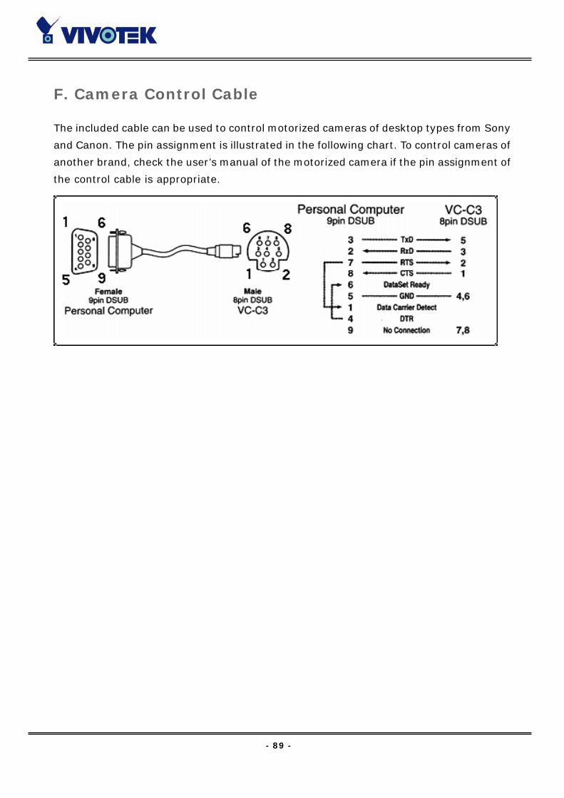
- 89 -
F. Camera Control Cable
The included cable can be used to control motorized cameras of desktop types from Sony
and Canon. The pin assignment is illustrated in the following chart. To control cameras of
another brand, check the user’s manual of the motorized camera if the pin assignment of
the control cable is appropriate.
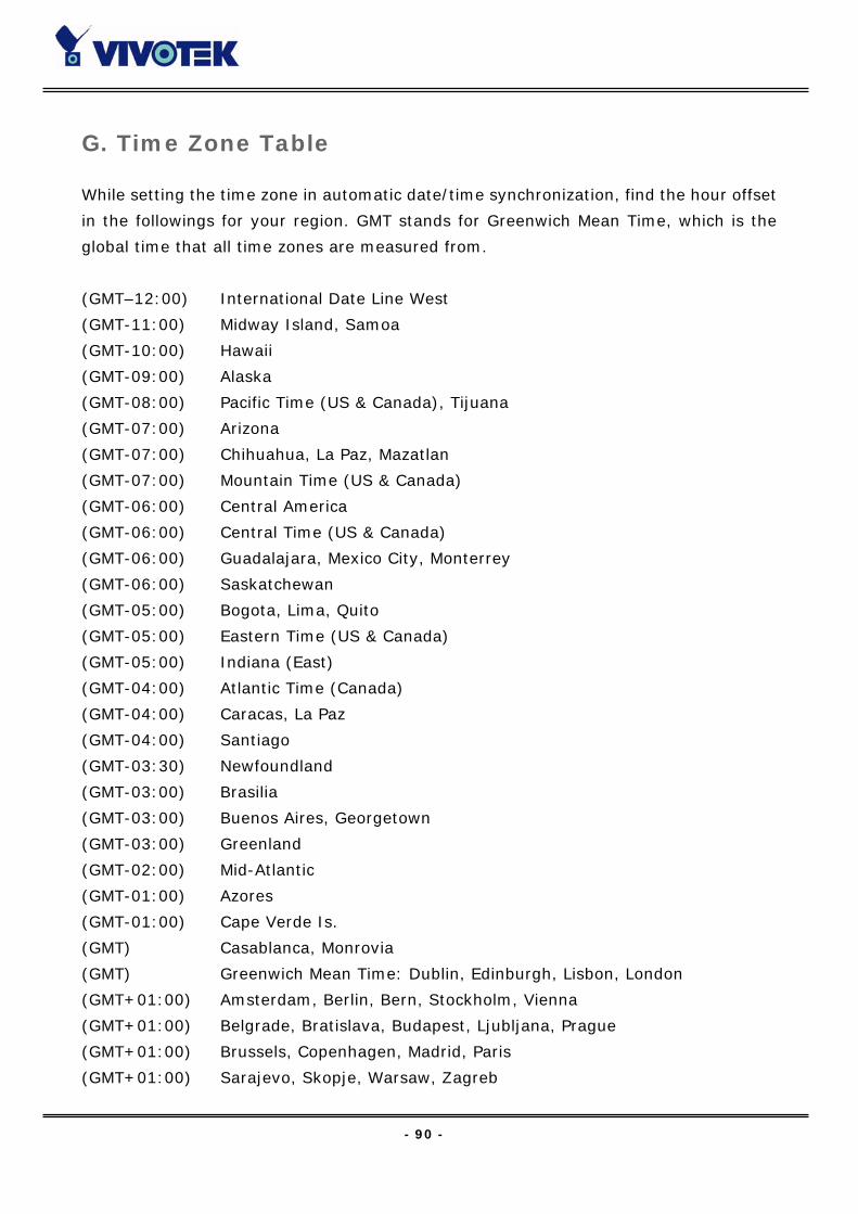
- 90 -
G. Time Zone Table
While setting the time zone in automatic date/time synchronization, find the hour offset
in the followings for your region. GMT stands for Greenwich Mean Time, which is the
global time that all time zones are measured from.
(GMT–12:00) International Date Line West
(GMT-11:00) Midway Island, Samoa
(GMT-10:00) Hawaii
(GMT-09:00) Alaska
(GMT-08:00) Pacific Time (US & Canada), Tijuana
(GMT-07:00) Arizona
(GMT-07:00) Chihuahua, La Paz, Mazatlan
(GMT-07:00) Mountain Time (US & Canada)
(GMT-06:00) Central America
(GMT-06:00) Central Time (US & Canada)
(GMT-06:00) Guadalajara, Mexico City, Monterrey
(GMT-06:00) Saskatchewan
(GMT-05:00) Bogota, Lima, Quito
(GMT-05:00) Eastern Time (US & Canada)
(GMT-05:00) Indiana (East)
(GMT-04:00) Atlantic Time (Canada)
(GMT-04:00) Caracas, La Paz
(GMT-04:00) Santiago
(GMT-03:30) Newfoundland
(GMT-03:00) Brasilia
(GMT-03:00) Buenos Aires, Georgetown
(GMT-03:00) Greenland
(GMT-02:00) Mid-Atlantic
(GMT-01:00) Azores
(GMT-01:00) Cape Verde Is.
(GMT) Casablanca, Monrovia
(GMT) Greenwich Mean Time: Dublin, Edinburgh, Lisbon, London
(GMT+01:00) Amsterdam, Berlin, Bern, Stockholm, Vienna
(GMT+01:00) Belgrade, Bratislava, Budapest, Ljubljana, Prague
(GMT+01:00) Brussels, Copenhagen, Madrid, Paris
(GMT+01:00) Sarajevo, Skopje, Warsaw, Zagreb

- 91 -
(GMT+01:00) West Central Africa
(GMT+02:00) Athens, Istanbul, Minsk
(GMT+02:00) Bucharest
(GMT+02:00) Cairo
(GMT+02:00) Harare, Pretoria
(GMT+02:00) Helsinki, Kyiv, Riga, Sofia, Tallinn, Vilnius
(GMT+02:00) Jerusalem
(GMT+03:00) Baghdad
(GMT+03:00) Kuwait, Riyadh
(GMT+03:00) Moscow, St. Petersburg, Volgograd
(GMT+03:00) Nairobi
(GMT+03:30) Tehran
(GMT+04:00) Abu Dhabi, Muscat
(GMT+04:00) Baku, Tbilisi, Yerevan
(GMT+04:30) Kabul
(GMT+05:00) Ekaterinburg
(GMT+05:00) Islamabad, Karachi, Tashkent
(GMT+05:30) Chennai, Kolkata, Mumbai, New Delhi
(GMT+05:45) Kathmandu
(GMT+06:00) Almaty, Novosibirsk
(GMT+06:00) Astana, Dhaka
(GMT+06:00) Sri Jayawardenepura
(GMT+06:30) Rangoon
(GMT+07:00) Bangkok, Hanoi, Jakarta
(GMT+07:00) Krasnoyarsk
(GMT+08:00) Beijing, Chongqing, Hongkong, Urumqi
(GMT+08:00) Taipei
(GMT+08:00) Irkutsk, Ulaan Bataar
(GMT+08:00) Kuala Lumpur, Singapore
(GMT+08:00) Perth
(GMT+09:00) Osaka, Sapporo, Tokyo
(GMT+09:00) Seoul
(GMT+09:00) Yakutsk
(GMT+09:30) Adelaide
(GMT+09:30) Darwin
(GMT+10:00) Brisbane
(GMT+10:00) Canberra, Melbourne, Sydney
(GMT+10:00) Guam, Port Moresby

- 92 -
(GMT+10:00) Hobart
(GMT+10:00) Vladivostok
(GMT+11:00) Magadan, Solomon Is., New Caledonia
(GMT+12:00) Auckland, Wellington
(GMT+12:00) Fiji, Kamchatka, Marshall Is..
(GMT+13:00) Nuku’alofa
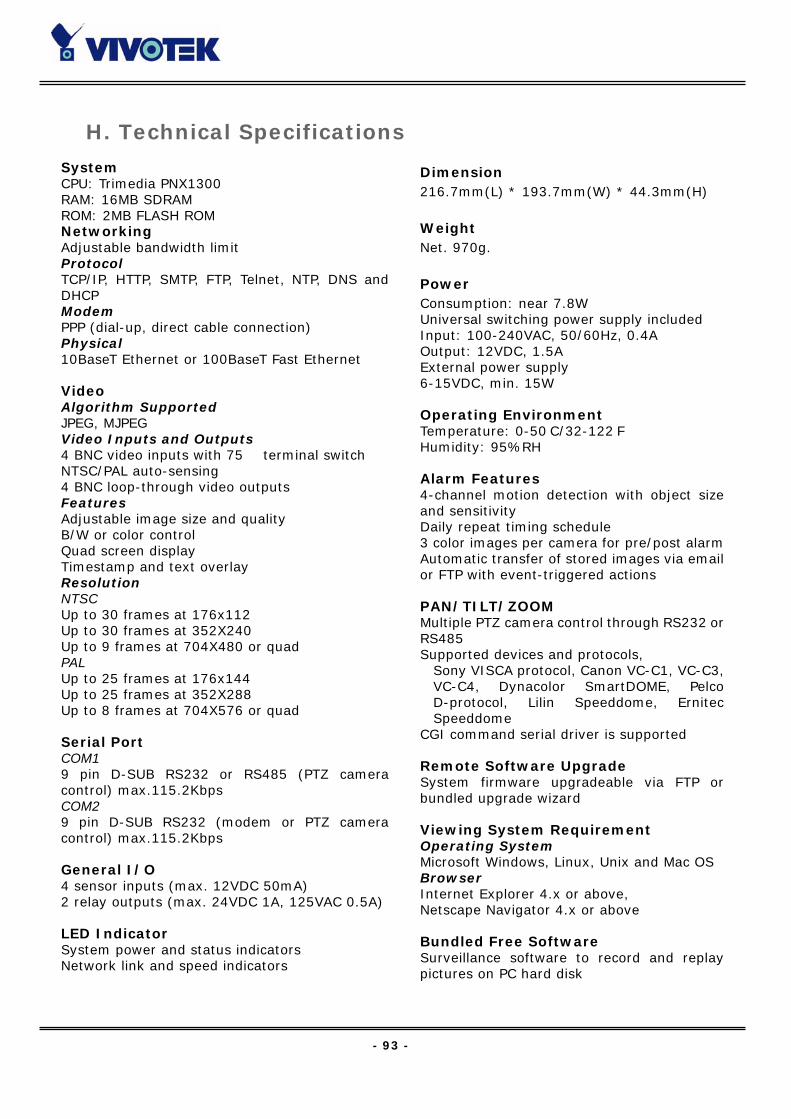
- 93 -
H. Technical Specifications
System CPU: Trimedia PNX1300 RAM: 16MB SDRAM ROM: 2MB FLASH ROM Networking Adjustable bandwidth limit Protocol TCP/IP, HTTP, SMTP, FTP, Telnet, NTP, DNS andDHCP Modem PPP (dial-up, direct cable connection) Physical 10BaseT Ethernet or 100BaseT Fast Ethernet Video Algorithm Supported JPEG, MJPEG Video Inputs and Outputs 4 BNC video inputs with 75Ω terminal switch NTSC/PAL auto-sensing 4 BNC loop-through video outputs Features Adjustable image size and quality B/W or color control Quad screen display Timestamp and text overlay Resolution NTSC Up to 30 frames at 176x112 Up to 30 frames at 352X240 Up to 9 frames at 704X480 or quad PAL Up to 25 frames at 176x144 Up to 25 frames at 352X288 Up to 8 frames at 704X576 or quad Serial Port COM1 9 pin D-SUB RS232 or RS485 (PTZ cameracontrol) max.115.2Kbps COM2 9 pin D-SUB RS232 (modem or PTZ cameracontrol) max.115.2Kbps General I/O 4 sensor inputs (max. 12VDC 50mA) 2 relay outputs (max. 24VDC 1A, 125VAC 0.5A) LED Indicator System power and status indicators Network link and speed indicators
Dimension 216.7mm(L) * 193.7mm(W) * 44.3mm(H)
Weight Net. 970g.
Power Consumption: near 7.8W Universal switching power supply included Input: 100-240VAC, 50/60Hz, 0.4A Output: 12VDC, 1.5A External power supply 6-15VDC, min. 15W Operating Environment Temperature: 0-50°C/32-122°F Humidity: 95%RH Alarm Features 4-channel motion detection with object sizeand sensitivity Daily repeat timing schedule 3 color images per camera for pre/post alarmAutomatic transfer of stored images via emailor FTP with event-triggered actions PAN/TILT/ZOOM Multiple PTZ camera control through RS232 orRS485 Supported devices and protocols,
Sony VISCA protocol, Canon VC-C1, VC-C3,VC-C4, Dynacolor SmartDOME, PelcoD-protocol, Lilin Speeddome, ErnitecSpeeddome
CGI command serial driver is supported Remote Software Upgrade System firmware upgradeable via FTP orbundled upgrade wizard Viewing System Requirement Operating System Microsoft Windows, Linux, Unix and Mac OSBrowser Internet Explorer 4.x or above, Netscape Navigator 4.x or above Bundled Free Software Surveillance software to record and replaypictures on PC hard disk