Embed Size (px)
Citation preview
www.itcon.org - Journal of Information Technology in Construction - ISSN 1874-4753
ITcon Vol. 16 (2010), Malmgren et al., pg. 697
PRODUCT MODELING OF CONFIGURABLE BUILDING SYSTEMS –
A CASE STUDY
SUBMITTED: December 2009
REVISED: August 2010
PUBLISHED: May 2011 at http://www.itcon/2011/41
EDITOR: Turk Ž.
Linus Malmgren, M. Sc.
Div. of Structural Engineering, Lund University, Sweden
mailto:[email protected]
Patrik Jensen, M. Sc.
Div. of Construction Engineering and Management, Luleå University of Technology, Sweden
mailto:[email protected]
Thomas Olofsson, Prof.
Div. of Construction Engineering and Management, Luleå University of Technology, Sweden
mailto:[email protected]
SUMMARY: This paper investigates a Swedish house manufactures building system regarding the documenta-
tion and information structures. The aim is to evaluate how product modeling technology can be used to facili-
tate product customization. By dividing the product in four different views the complexity of the product can be
reduced and each view represent the interest of customer, engineering, production and assembly respectively.
The analysis shows that the connections between the different view, i.e. the information transfer, is an area for
potential improvements and little attention has been devoted to transfer information upstream from manufactu-
ring and engineering to the customer view. The lack of information transfer can often lead to ad-hoc solutions in
the customization process. We believe that successful cooperation and information exchange between these four
views is the key to future development and customize-to-order configuration.
KEYWORDS: industrialized construction, modular houses, building product model, product customization
REFERENCE: Linus Malmgren, M. Sc., Patrik Jensen, M. Sc., Thomas Olofsson, Prof., M. Sc. (2011) Product
modeling of configurable building systems – a case study, Journal of Information Technology in Construction
(ITcon), Vol. 16, pg. 697-712, http://www.itcon.org/2011/41
COPYRIGHT: © 2011 The authors. This is an open access article distributed under the terms of the Creative
Commons Attribution 3.0 unported (http://creativecommons.org/licenses/by/3.0/), which
permits unrestricted use, distribution, and reproduction in any medium, provided the
original work is properly cited.
ITcon Vol. 16 (2010), Malmgren et al., pg. 698
1. INTRODUCTION
Production methods of Swedish house manufacturers vary from almost manual carpentry to highly automated
manufacturing units. Earlier studies in Sweden have concluded that information management in Swedish timber
house manufacturing is relatively poor and similar to on-site construction (Johnsson et al. 2006; Persson et al.
2009). The information gap between sales, engineering and production departments often leads to situations
where customer requirements are implemented using ad-hoc solutions that are not suitable for the existing pro-
duction system. Traditional methods and use of project oriented IT-tools do not support the industrialization and
automation of the house manufacturing industry (Johnsson et al. 2007). Therefore, new methods and IT systems
need to be developed and integrated in the design and production of manufactured houses.
On the other hand, many of the developed building systems have evolved during decades and cannot easily be
adapted to fluctuating markets. Also, the lack of proper description of the building system makes it harder to
adapt to volatile customers’ requirements. Development of modularized product platforms is one strategy for
mass customization (Erixon 1998) that often has been used by the manufacturing industry. The customization
process needs information about the product structure, its constraints as well as the customer requirements in
order to develop a successful configuration and modularization strategy (Yang et al. 2008). The product docu-
mentation in construction industry often consists of drawing files in CAD libraries (predominantly AutoCAD)
that make the products difficult to use in a customization process. According to Nasereddin et al (2007), ade-
quate documentation of the product structure and customization processes is essential for the productivity and
quality of the end product. The “ad-hoc” customization of initially well-standardized technical solutions is one
of the main reasons for the decreasing profits in the Swedish prefabricated single-house industry (Brege 2008).
This paper evaluates a product family of a Swedish industrialized house manufacturer from two perspectives:
(1) how the product is designed, how information is shared and how the product is offered to customers, and
(2) what features customers request. The intention is to find a successful form for product documentation that
will grasp product information from customer design through engineering and production of the final product.
The case study has been performed on a product that is offered at a competitive price with limited possibilities
for customization. This makes it easier to see if it can really be managed to foresee customer demands, and if
the product can be modularized according to customer needs.
2. OBJECTIVES AND METHOD
The objective of the study is to investigate how product modeling technology can be used by industrialized
house manufacturers in the customization of a building system. More specifically three research questions are
formulated:
1. How can an existing building system be documented using product modeling methodology to
cover the process from sales to the realization of a customized building?
2. How well can the existing building system be adapted to customers’ requirements?
3. How is the flow of information from sales to realization of the building affected by the use of
product modeling technology?
An investigation of a Swedish company has been performed where three methods of collecting information were
used for the case study of the building system in the research project:
Studying drawings and documents of the building system as well as the production system
Interviews with sales and engineering department
Workshops with the engineering department to verify the product model of the building system.
The existing description of the building system is used as a basis for creating the product structure presented in
section 4. From drawings and documents a first description of the product design and production constraints were
established. This part of the study was performed with the intention to create a first product model of the case study
building system. The information was then illustrated in product views (see section 4.4.1-4.4.4), which were used to
refine and verify the product structure of the building system with the engineering department in a workshop. The
refined version presented after the final workshop is the version published in this paper.

ITcon Vol. 16 (2010), Malmgren et al., pg. 699
Two methods were used to define a set of general requirements from a typical customer used in the study des-
cribed in section 4.5:
Information gathered from a Swedish the survey of housing standards (Horsman 2008)
Interviews with the sales department in the company.
3. BACKGROUND
3.1 Information and product models
An information model represents a part of the real world, in some cases referred to as the universe of discourse
(Björk 1995). All information models are unique, as well as the process of creating them. According to Schenck
and Wilson (1994) an information model should be precise, complete, non-ambiguous, minimally redundant and
implementation independent.
Companies that develop, manufacture and sell complex products need to define and manage product information
during all stages of the life cycle (Claesson et al. 2001). These information models that contain data of both the
product and the processes supporting the product’s life cycle are generally referred to as product models. A buil-
ding information model, BIM, is a product model defined for building products. A well known model standard
for buildings is the Industry Foundation Classes (IFC) of the BuildingSmart initiative (BuildingSmart 2009).
The team defining the set of rules used to interpret the data in the product model, i.e. the model schema, consists
of product modeling experts and domain experts possessing knowledge of the product and the supporting life
cycle processes. The definition of product model schemas often contains a mix of various methodologies, for
example top-down and bottom-up in an iterative process (Hvam et al. 2008).
According to Björk (1995) the creation of a product model for buildings start by defining the classes of the main
building parts and the systems they form, i.e. structural system, installation system etc. The next step is the defi-
nition of the most important attributes of these classes and the relationships between these object classes needed
in many applications. A similar approach is suggested by Schenck and Wilson (1994), where basic classes and
relationships often can be extracted from the domain experts by frequently used nouns and verbs, were nouns
represent the physical objects and verbs represent the relationships between the objects.
There are aspects that have significance in the choice of the information modeling language (Björk 1995):
Capability for modeling the semantics of the universe of discourse without simplifications caused
by the information modeling language
Capability for modeling the designer’s intents and aims
Support for the evolutionary process of design (extendibility of the schema)
Usefulness for the exchange of data between heterogeneous computer applications in construction
Technical feasibility for implementation using current commercial software
Realistic possibilities for achieving standardization (in terms of reaching consensus in
standardization bodies and expenditure)
A popular language used in many product model applications such as the STEP and IFC model standard is the
EXPRESS modeling language (ISO 10303-11 2004).
3.2 Product configuration
Product configuration is described as an effective mean of structuring products and standardization, but also a
way of presenting the product for the customer (Hvam et al. 2008). Also, the structuring of products in product
models becomes a common view of the product ranges in the company that can be shared by the people involved
in the support of the product life cycle, e.g. sales, design, production and maintenance. Before a configuration
project is initiated, the following issues need to be resolved:
The range of products to be part of a configuration system need to be structured in some form of
product structure. Often conflicting views exist in the company regarding rules, degree of detail
etc., these issues have to be resolved before any product modeling initiative is launched.
ITcon Vol. 16 (2010), Malmgren et al., pg. 700
Companies have to decide what parts of the product range should be included in a product confi-
guration system. Probably, not all products are suitable for configuration.
The information needed for the product configuration project has to be collected. This information
often resides in documents, CAD files and different types of management systems such as ERP,
SCM and CRM. It is also to be found as tacit knowledge of the product specialists within the
company.
How should product information be stored, updated and maintained? The product model will have
to be constructed so that these parameters are effectively considered.
Leckner and Lacher (2003) pointed out that customer oriented product modeling is governed by the flexibility
required in the product configuration process. They defined different types of flexibility or degrees of freedom
of a product:
Alternative component models where the customer can choose exactly one from a set of mutually
exclusive alternative components
Optional component models where the customer can select optional components not obligatory for
the product in an add-on configuration process
Attribute enumerated set model where the customer can choose a component with one value from
a predefined set of possible values
Attribute numerical interval model where the customer can choose a component with one value
within an interval boundary.
The result of a product configuration is a customer specific product model where the product properties and
functions are determined and specifications of what modules and components will be produced and assembled
are given (Jørgensen 2001).
3.3 Customer requirements
The increasing demands on products matching customers’ individual preferences put pressure on manufacturing
companies to offer more product varieties (Veenstra et al. 2006). Still, the economical benefits of mass produc-
tion need to be retained to keep the production cost at an acceptable level.
Since the cost of developing a building system is high, system analysis and customers surveys of the target market
segments are important in the design of modularized product platforms (Bertelsen 2005). This approach is well
known in the manufacturing industry but often overseen in construction companies; hence customer requirements
are treated only in the specific one-off project and often specified by the client in a building program. However, a
product platform needs to be adapted to a variety of customers in the targeted market segment to be competitive.
Therefore, a number of methods have been developed to map customer demands against product properties. Quality
Function Deployment (QFD) is a widely used method that emerged in Japan (Akao 1990). QFD introduces the cus-
omer needs and requirements early in the process and governs the product development in many ways.
The transformation of customer values and requirements into product properties are often performed by a multi-
discipline QFD-team. In traditional procurement systems where different people perform design and construction,
the QFD methodology can potentially create problems. The “cross-functionality” approach often used when
conducting a QFD, can be difficult to achieve in traditional construction projects where the design, engineering and
production planning and execution phases are separated. The QFD methodology can be suitable for projects where
one part is responsible for both the design and production, and the functional requirements for both the product and
the production can be defined in an early stage of the project and not as a parade of trades (Dikmen et al. 2004).
The QFD analysis needs the customer values or requirements as input. This is often evaluated in market surveys
where different market segments are surveyed using statistics and customer questionnaires (Eldin et al. 2003).

ITcon Vol. 16 (2010), Malmgren et al., pg. 701
4. CASE STUDY
4.1 Investigated company
The investigated company is one of Sweden’s leading modular family house manufacturers. Since the start over
50 years ago, approximately 43 000 houses have been built. The company delivers turnkey ready houses and takes
total responsibility for the delivery. Sales, design, manufacturing and on-site assembly are performed by in-house
staff. The company exports houses to Denmark, Germany and Japan. Customers include both private individuals
and business to business clients. In 2008, the turnover was € 91 Million and in total the company employs a work-
force of approximately 320 people. Houses are manufactured in both contemporary and classic designs and the
targeted end customer group is predominantly middle- and upper middle class.
4.2 The investigated product family
The investigated product family is an affordable house model offered by the manufacturer. It features five
alternate models all based on the same construction principles. The design is classic/contemporary with a
relatively high standard regarding kitchen appliances, surface materials etc. All models are detached houses
spanning between 100-180 square meters of living space, manufactured in the production facilities of the
manufacturer and delivered and assembled as turnkey houses to the customers.
The product family is offered at a competitive price with limited possibilities for customization. The product
family is designed by the company associated architect with the intension of creating solutions that do not need
to be modified. The strategy is to streamline house production and minimize one-of-a-kind operations. The cus-
tomization options are mainly selection of façade, kitchen appliances and surface materials.
4.3 Product documentation system
CAD is the predominant product description system for the investigated product family. Plain AutoCAD1 is
used for design and customization of all house models in the company. The AutoCAD system is used for the
architectural, structural and HVAC design. Production design rules have been implemented in AutoCAD using
the VBA interface2. The production design rules with associated parameters are stored in a MS Access database.
The company is also using an in-house developed MRP/CRM-system (Material Resource Planning / Customer
Relation Management) that keeps track of stock and orders linked with customer data. Product related informa-
tion is consequently kept in two systems, the AutoCAD and MRP system, depending on where the information
is created, i.e. design information is kept in the CAD system and information related to purchase, stock and cus-
tomer is kept in the MRP/CRM system.
As a complement to the design rules in the CAD system, written manuals exist that contain information about
rules and limitations of the building system. There is also a manual describing the design rules of the building
system to external users, for example architects, structural engineers and sales agents. It includes the main
aspects such as, facade heights, floor plan, openings, roof and floor structure, etc. Other product related infor-
mation is mostly distributed within the organization through documents and drawings.
4.4 Current process
The sales department is often asked to adapt the offered product to fit customer’s individual needs. These changes
are often not possible to fulfill without violating the rules of the building system. Despite the managements’ inten-
tion to have relatively restricted customization policy, changes to the original concept are often introduced by the
sales department to satisfy customers. Consequently, these adaptations cause problems both in engineering and pro-
duction when ad-hoc solutions need to be applied to specific customers. Also, the implications, i.e. additional costs
for adaption of the product by the engineering and production teams, are hard to evaluate. Furthermore, these ad-
hoc solutions are often not reused in other projects since the specific solutions are not analyzed in an attempt to
modify and incorporate the changes in the product family.
1 http://usa.autodesk.com/adsk/servlet/pc/index?id=13779270&siteID=123112#
2 Visual Basic for Applications, http://usa.autodesk.com/adsk/servlet/index?siteID=123112&id=770215
ITcon Vol. 16 (2010), Malmgren et al., pg. 702
Findings from interviews with sales and engineering emphasize that there are important issues that need to be
resolved in order to improve efficiency:
The product documentation needs to be adapted to the different processes in the company, e.g. in
the sales, engineering and production views.
Changes in one view, e.g. sales view, should be easily traceable in the engineering and production
views and vice versa.
Changes of the product concept affecting the production system should be made in a product deve-
lopment process from a strategic point of view making the building product more adaptable to
customers’ requirements. Otherwise, the costs of introducing ad-hoc solutions should be part of
the offer to the customer.
In the next section, we present a conceptual solution of the product documentation issue using different views of
a product model of the investigated product family.
4.5 Organizing the product information in product views
Hvam et al. (2008) suggest a methodology based on the representation of the product in a hierarchical structure
using the Unified Model Language (UML) 3
. These representations or product views of the product model are
used to package and present the product information for a targeted set of stakeholders (knowledge domain).
IKEA is an example of a company working with different product views. IKEA’s kitchen configuration program
makes it possible to design and get a price of a custom made kitchen directly on their website (IKEA 2009).
Information essential for the customer such as cabinet doors and colors etc, are presented in the customer view
of the product. In the production view of the customized kitchen the types of colors and cabin doors is described
by article numbers, color codes and other related information used in the production of the custom made kitchen.
This information is added in the manufacturers CAD application, which is different from the one used on the
web site.
The use of process related product views is common in the manufacturing industry and to some extent also in the
construction industry. However, the different views in the construction industry are mostly connected to the
architectural, HVAC and structural disciplines using drawings and documents, thereby making the integration
and coordination between these different disciplines a tedious manual task prone to errors (Jongeling and Olofs-
son 2007).
The product views with their related product structures also constitute the point of departure for organizing,
storing and communicating product information both internally and externally. This would facilitate information
sharing in the customization process (Hvam et al. 2008; Johnson et al. 2007).
Accordingly, in our case study the following product views were defined:
The Customer view represents an instance of the product model as seen by end customers and sales
agents which represent the company. This view represents the features of the product family re-
quested by customers.
The Engineering view represents the various customized alternatives of the product model from an
engineering point of view. This view represents the most important systems for the technical reali-
zation of the product features requested by the customers (such as structural, installation etc.).
The Production view describes the different building parts to be manufactured at the production
facility. It contains information relevant for the supply chain and the factory production units.
The Assembly view describes how the product will be assembled on site. Assembly instructions,
the order of delivery and assembly of prefabricated elements, schedules etc. are example of infor-
mation relevant in the assembly view.
Compared to the model presented by Hvam et al. (2008) the assembly view has been added to the product views
in the case study because this is one essential factor that differentiates the construction industry from manufac-
3 http://www.uml.org/
ITcon Vol. 16 (2010), Malmgren et al., pg. 703
turing. The assembly of the final product on site needs to be managed separately, in contrast the manufacturing
industry, in general, considering the product finished when it leaves the factory.
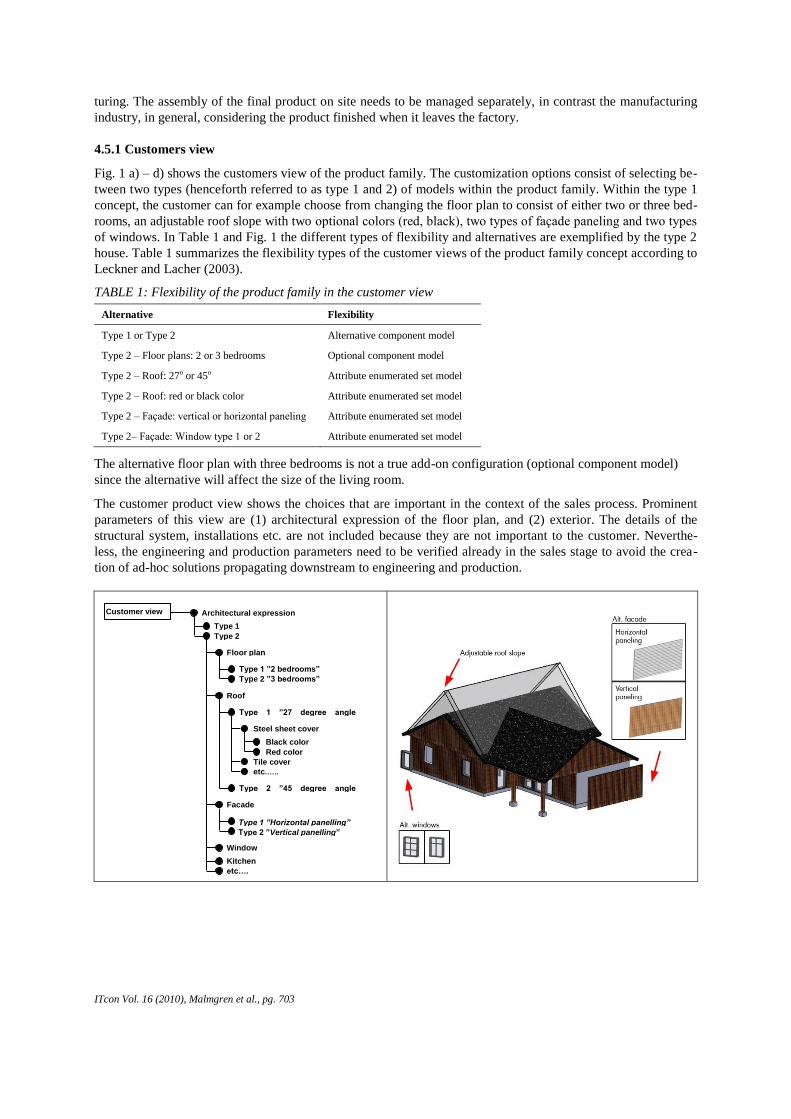
4.5.1 Customers view
Fig. 1 a) – d) shows the customers view of the product family. The customization options consist of selecting be-
tween two types (henceforth referred to as type 1 and 2) of models within the product family. Within the type 1
concept, the customer can for example choose from changing the floor plan to consist of either two or three bed-
rooms, an adjustable roof slope with two optional colors (red, black), two types of façade paneling and two types
of windows. In Table 1 and Fig. 1 the different types of flexibility and alternatives are exemplified by the type 2
house. Table 1 summarizes the flexibility types of the customer views of the product family concept according to
Leckner and Lacher (2003).
TABLE 1: Flexibility of the product family in the customer view
Alternative Flexibility
Type 1 or Type 2 Alternative component model
Type 2 – Floor plans: 2 or 3 bedrooms Optional component model
Type 2 – Roof: 27o or 45o Attribute enumerated set model
Type 2 – Roof: red or black color Attribute enumerated set model
Type 2 – Façade: vertical or horizontal paneling Attribute enumerated set model
Type 2– Façade: Window type 1 or 2 Attribute enumerated set model
The alternative floor plan with three bedrooms is not a true add-on configuration (optional component model)
since the alternative will affect the size of the living room.
The customer product view shows the choices that are important in the context of the sales process. Prominent
parameters of this view are (1) architectural expression of the floor plan, and (2) exterior. The details of the
structural system, installations etc. are not included because they are not important to the customer. Neverthe-
less, the engineering and production parameters need to be verified already in the sales stage to avoid the crea-
tion of ad-hoc solutions propagating downstream to engineering and production.
Architectural expression
Type 1
Type 2
Floor plan
Type 1 ”2 bedrooms”
Type 2 ”3 bedrooms”
Roof
Type 1 ”27 degree angle slope”
Type 2 ”45 degree angle slope”
Steel sheet cover
Tile cover
Customer view
etc.…..
Facade
Type 1 ”Horizontal panelling”
Type 2 ”Vertical panelling”
Window
Kitchen
etc….
Black color
Red color
ITcon Vol. 16 (2010), Malmgren et al., pg. 704
FIG. 1: The customer view of the product family Type 2 alternative.
FIG 1a) shows the product structure, 1b) the façade, 1c) the interior floor plan and 1d) an example how the
configured product is presented for the customer.
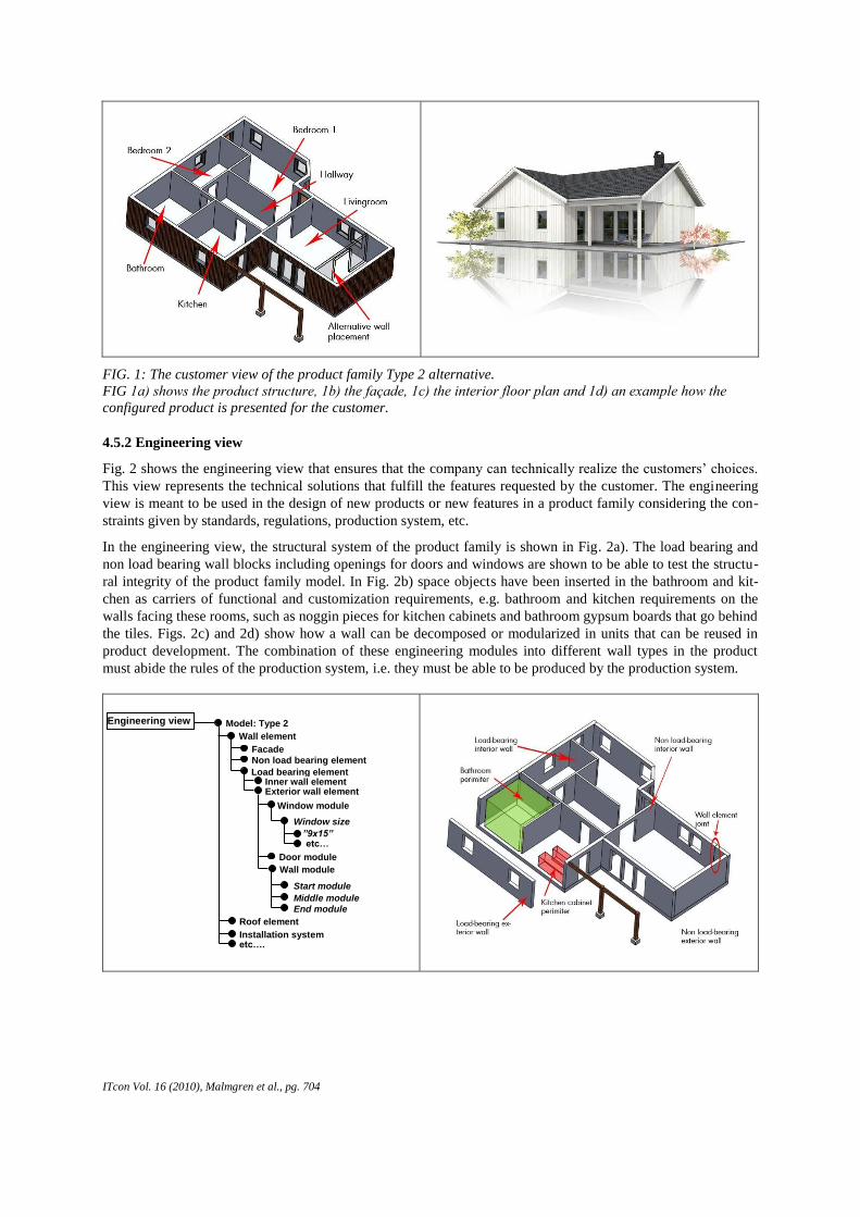
4.5.2 Engineering view
Fig. 2 shows the engineering view that ensures that the company can technically realize the customers’ choices.
This view represents the technical solutions that fulfill the features requested by the customer. The engineering
view is meant to be used in the design of new products or new features in a product family considering the con-
straints given by standards, regulations, production system, etc.
In the engineering view, the structural system of the product family is shown in Fig. 2a). The load bearing and
non load bearing wall blocks including openings for doors and windows are shown to be able to test the structu-
ral integrity of the product family model. In Fig. 2b) space objects have been inserted in the bathroom and kit-
chen as carriers of functional and customization requirements, e.g. bathroom and kitchen requirements on the
walls facing these rooms, such as noggin pieces for kitchen cabinets and bathroom gypsum boards that go behind
the tiles. Figs. 2c) and 2d) show how a wall can be decomposed or modularized in units that can be reused in
product development. The combination of these engineering modules into different wall types in the product
must abide the rules of the production system, i.e. they must be able to be produced by the production system.
Model: Type 2
Wall element
Facade Non load bearing element
Window module
Door module
Window size
Engineering view
Roof element
Installation system etc….
”9x15” etc…
Load bearing element
Wall module
Start module
Middle module End module
Inner wall element Exterior wall element
ITcon Vol. 16 (2010), Malmgren et al., pg. 705
FIG. 2: The Engineering view of the product family type 2.
FIG. 2a) shows the product structure, 2b) the structural view of the interior floor,
2c) an example of a load bearing exterior wall and 2d) its modular composition.
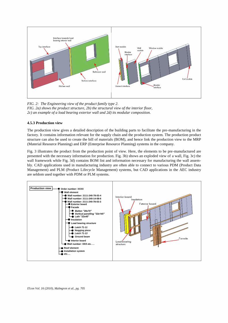
4.5.3 Production view
The production view gives a detailed description of the building parts to facilitate the pre-manufacturing in the
factory. It contains information relevant for the supply chain and the production system. The production product
structure can also be used to create the bill of materials (BOM), and hence link the production view to the MRP
(Material Resource Planning) and ERP (Enterprise Resource Planning) systems in the company.
Fig. 3 illustrates the product from the production point of view. Here, the elements to be pre-manufactured are
presented with the necessary information for production. Fig. 3b) shows an exploded view of a wall, Fig. 3c) the
wall framework while Fig. 3d) contains BOM list and information necessary for manufacturing the wall assem-
bly. CAD applications used in manufacturing industry are often able to connect to various PDM (Product Data
Management) and PLM (Product Lifecycle Management) systems, but CAD applications in the AEC industry
are seldom used together with PDM or PLM systems.
Order number: XXXX
Wall element
Wall number: 2111-240-78-03-4
Wall number: 2111-240-14-08-6
Insulation
Batten ”28x70”
Production view
Roof element
Installation system
etc….
Vertical panelling ”22x145”
Lath ”22x45”
Wall number: 2111-240-78-03-3
Load bearing structure
Latch 71-11
Nogging piece
Latch 71-13
Exterior board
Facade
Interior board
Wall number: XXX etc…..
Ground beam
ITcon Vol. 16 (2010), Malmgren et al., pg. 706
FIG. 3: The Production view of a customized order.
FIG. 3a) shows the product structure, 3b) an exploded view of the highlighted wall element,
3c) the framework of the wall and 3d) its BOM list and manufacturing information.
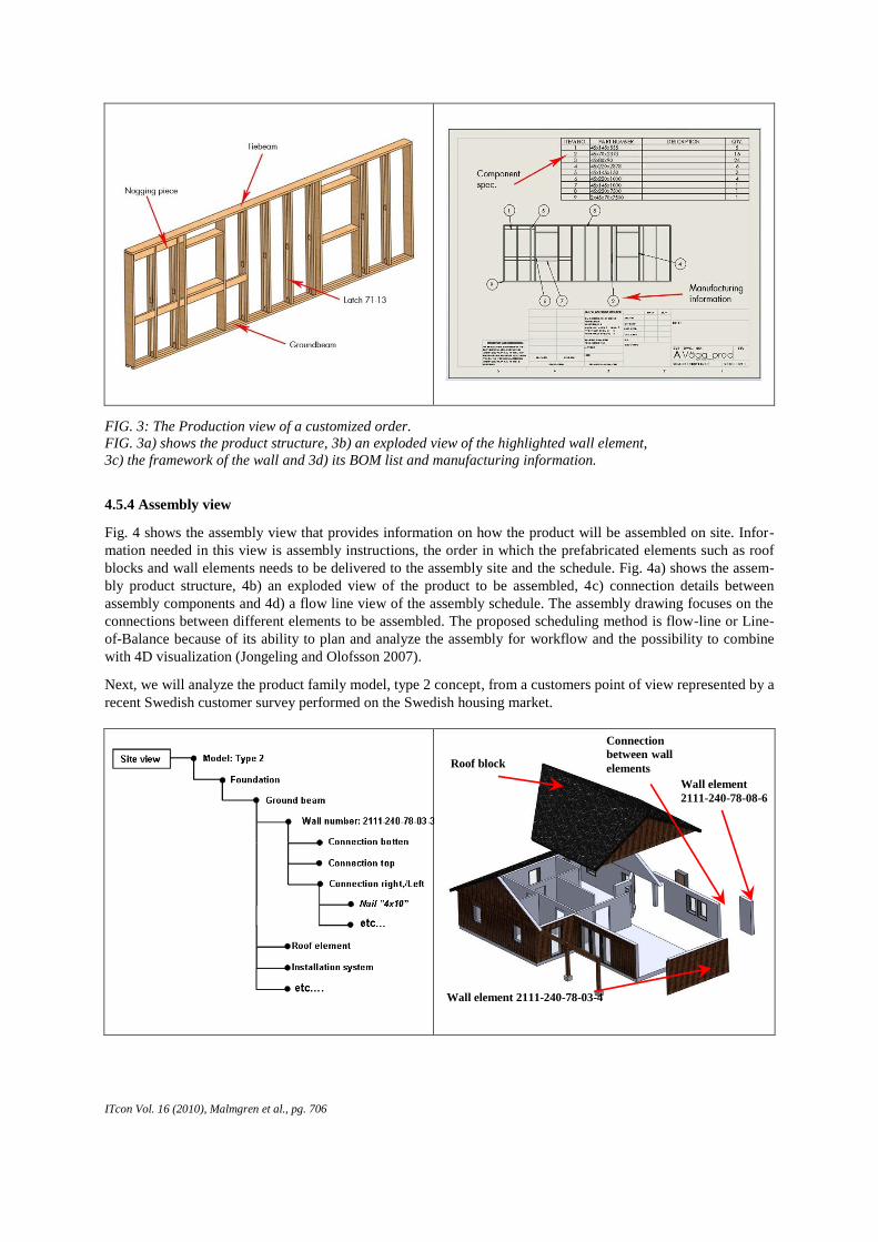
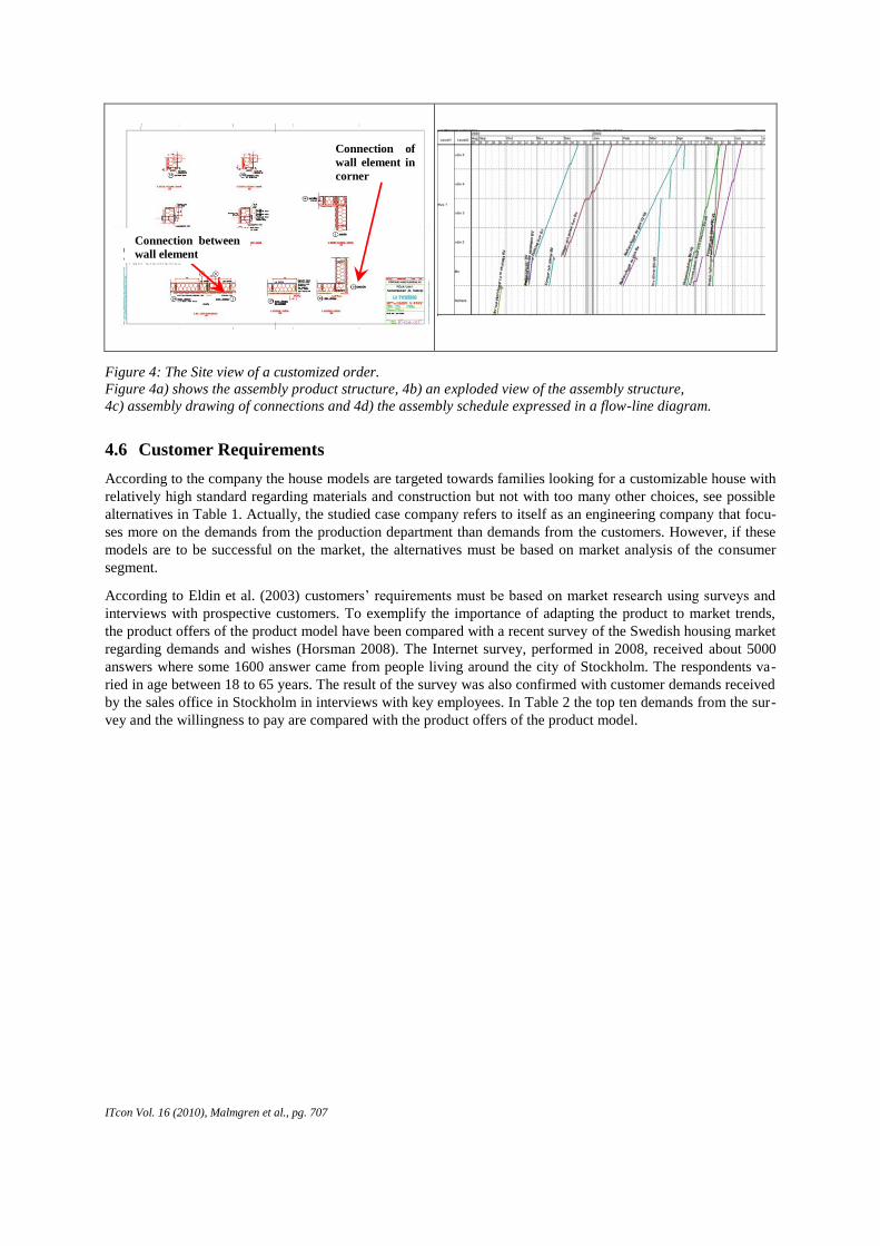
4.5.4 Assembly view
Fig. 4 shows the assembly view that provides information on how the product will be assembled on site. Infor-
mation needed in this view is assembly instructions, the order in which the prefabricated elements such as roof
blocks and wall elements needs to be delivered to the assembly site and the schedule. Fig. 4a) shows the assem-
bly product structure, 4b) an exploded view of the product to be assembled, 4c) connection details between
assembly components and 4d) a flow line view of the assembly schedule. The assembly drawing focuses on the
connections between different elements to be assembled. The proposed scheduling method is flow-line or Line-
of-Balance because of its ability to plan and analyze the assembly for workflow and the possibility to combine
with 4D visualization (Jongeling and Olofsson 2007).
Next, we will analyze the product family model, type 2 concept, from a customers point of view represented by a
recent Swedish customer survey performed on the Swedish housing market.
Roof block
Wall element 2111-240-78-03-4
Wall element
2111-240-78-08-6
Connection
between wall
elements
ITcon Vol. 16 (2010), Malmgren et al., pg. 707
Figure 4: The Site view of a customized order.
Figure 4a) shows the assembly product structure, 4b) an exploded view of the assembly structure,
4c) assembly drawing of connections and 4d) the assembly schedule expressed in a flow-line diagram.
4.6 Customer Requirements
According to the company the house models are targeted towards families looking for a customizable house with
relatively high standard regarding materials and construction but not with too many other choices, see possible
alternatives in Table 1. Actually, the studied case company refers to itself as an engineering company that focu-
ses more on the demands from the production department than demands from the customers. However, if these
models are to be successful on the market, the alternatives must be based on market analysis of the consumer
segment.
According to Eldin et al. (2003) customers’ requirements must be based on market research using surveys and
interviews with prospective customers. To exemplify the importance of adapting the product to market trends,
the product offers of the product model have been compared with a recent survey of the Swedish housing market
regarding demands and wishes (Horsman 2008). The Internet survey, performed in 2008, received about 5000
answers where some 1600 answer came from people living around the city of Stockholm. The respondents va-
ried in age between 18 to 65 years. The result of the survey was also confirmed with customer demands received
by the sales office in Stockholm in interviews with key employees. In Table 2 the top ten demands from the sur-
vey and the willingness to pay are compared with the product offers of the product model.
Connection of
wall element in
corner
Connection between
wall element
ITcon Vol. 16 (2010), Malmgren et al., pg. 708
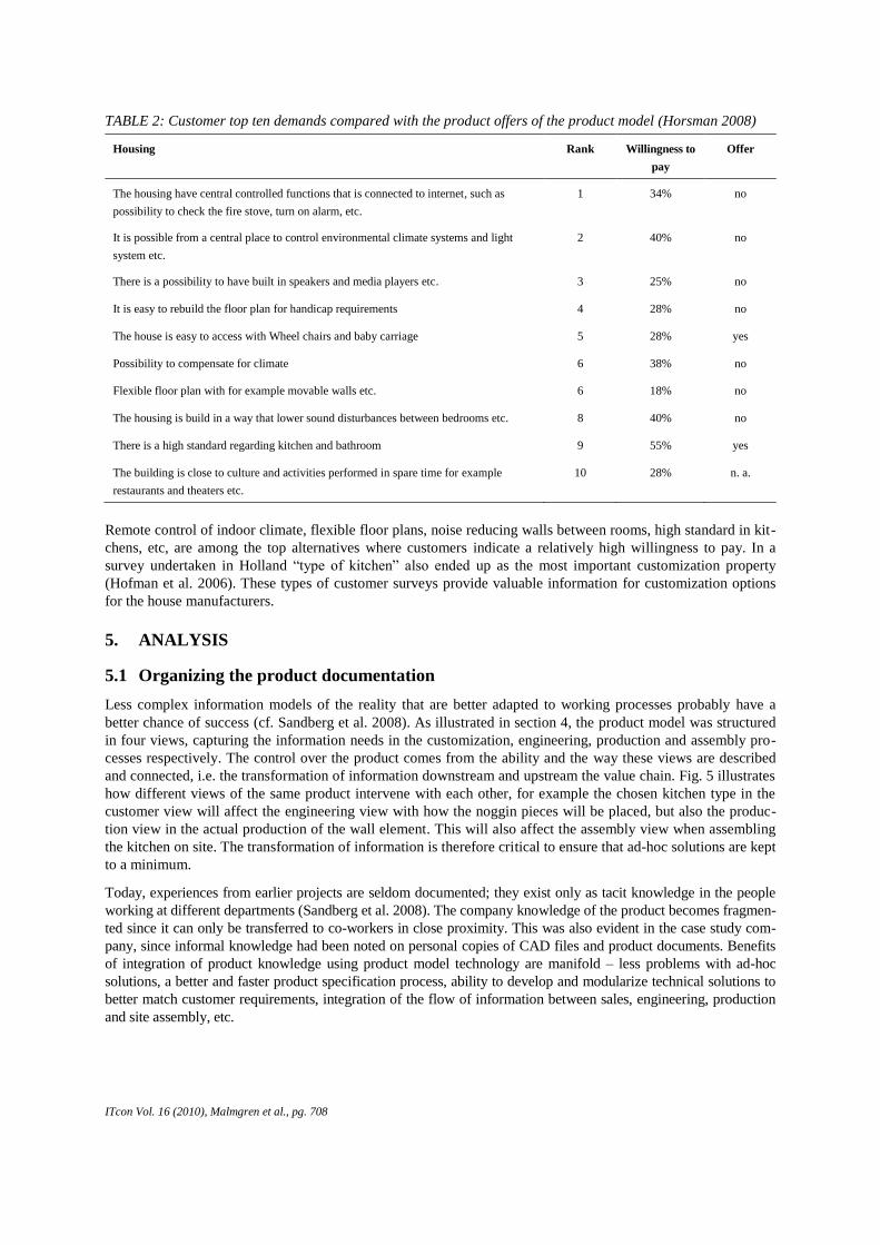
TABLE 2: Customer top ten demands compared with the product offers of the product model (Horsman 2008)
Housing Rank Willingness to
pay
Offer
The housing have central controlled functions that is connected to internet, such as
possibility to check the fire stove, turn on alarm, etc.
1 34% no
It is possible from a central place to control environmental climate systems and light
system etc.
2 40% no
There is a possibility to have built in speakers and media players etc. 3 25% no
It is easy to rebuild the floor plan for handicap requirements 4 28% no
The house is easy to access with Wheel chairs and baby carriage 5 28% yes
Possibility to compensate for climate 6 38% no
Flexible floor plan with for example movable walls etc. 6 18% no
The housing is build in a way that lower sound disturbances between bedrooms etc. 8 40% no
There is a high standard regarding kitchen and bathroom 9 55% yes
The building is close to culture and activities performed in spare time for example
restaurants and theaters etc.
10 28% n. a.
Remote control of indoor climate, flexible floor plans, noise reducing walls between rooms, high standard in kit-
chens, etc, are among the top alternatives where customers indicate a relatively high willingness to pay. In a
survey undertaken in Holland “type of kitchen” also ended up as the most important customization property
(Hofman et al. 2006). These types of customer surveys provide valuable information for customization options
for the house manufacturers.
5. ANALYSIS
5.1 Organizing the product documentation
Less complex information models of the reality that are better adapted to working processes probably have a
better chance of success (cf. Sandberg et al. 2008). As illustrated in section 4, the product model was structured
in four views, capturing the information needs in the customization, engineering, production and assembly pro-
cesses respectively. The control over the product comes from the ability and the way these views are described
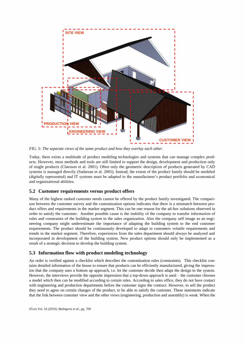
and connected, i.e. the transformation of information downstream and upstream the value chain. Fig. 5 illustrates
how different views of the same product intervene with each other, for example the chosen kitchen type in the
customer view will affect the engineering view with how the noggin pieces will be placed, but also the produc-
tion view in the actual production of the wall element. This will also affect the assembly view when assembling
the kitchen on site. The transformation of information is therefore critical to ensure that ad-hoc solutions are kept
to a minimum.
Today, experiences from earlier projects are seldom documented; they exist only as tacit knowledge in the people
working at different departments (Sandberg et al. 2008). The company knowledge of the product becomes fragmen-
ted since it can only be transferred to co-workers in close proximity. This was also evident in the case study com-
pany, since informal knowledge had been noted on personal copies of CAD files and product documents. Benefits
of integration of product knowledge using product model technology are manifold – less problems with ad-hoc
solutions, a better and faster product specification process, ability to develop and modularize technical solutions to
better match customer requirements, integration of the flow of information between sales, engineering, production
and site assembly, etc.
ITcon Vol. 16 (2010), Malmgren et al., pg. 709
FIG. 5: The separate views of the same product and how they overlay each other.
Today, there exists a multitude of product modeling technologies and systems that can manage complex prod-
ucts. However, most methods and tools are still limited to support the design, development and production only
of single products (Claesson et al. 2001). Often only the geometric description of products generated by CAD
systems is managed directly (Sudarsan et al. 2005). Instead, the extent of the product family should be modeled
(digitally represented) and IT systems must be adapted to the manufacturer’s product portfolio and economical
and organizational abilities.
5.2 Customer requirements versus product offers
Many of the highest ranked customer needs cannot be offered by the product family investigated. The compari-
son between the customer survey and the customization options indicates that there is a mismatch between pro-
duct offers and requirements in the market segment. This can be one reason for the ad-hoc solutions observed in
order to satisfy the customer. Another possible cause is the inability of the company to transfer information of
rules and constraints of the building system to the sales organization. Also the company self image as an engi-
neering company might underestimate the importance of adapting the building system to the end customer
requirements. The product should be continuously developed to adapt to customers volatile requirements and
trends in the market segment. Therefore, experiences from the sales department should always be analyzed and
incorporated in development of the building system. New product options should only be implemented as a
result of a strategic decision to develop the building system.
5.3 Information flow with product modeling technology
An order is verified against a checklist which describes the customization rules (constraints). This checklist con-
tains detailed information of the house to ensure that products can be efficiently manufactured, giving the impress-
ion that the company uses a bottom up approach, i.e. let the customer decide then adapt the design to the system.
However, the interviews provide the opposite impression that a top-down approach is used – the customer chooses
a model which then can be modified according to certain rules. According to sales office, they do not have contact
with engineering and production departments before the customer signs the contract. However, to sell the product
they need to agree on certain changes of the product, to be able to satisfy the customer. These statements indicate
that the link between customer view and the other views (engineering, production and assembly) is weak. When the
PRODUCTION VIEW
SITE VIEW
ENGINEERING VIEW
CUSTOMER VIEW
ITcon Vol. 16 (2010), Malmgren et al., pg. 710
customization process violates the rules of the building system, this information is not automatically transferred to
the engineering and production view which is a major source of ad-hoc solutions in production. Attempts to reduce
ad-hoc customization have been to offer fewer options, but this also increases the risk of removing the wrong opti-
ons from a customer perspective.
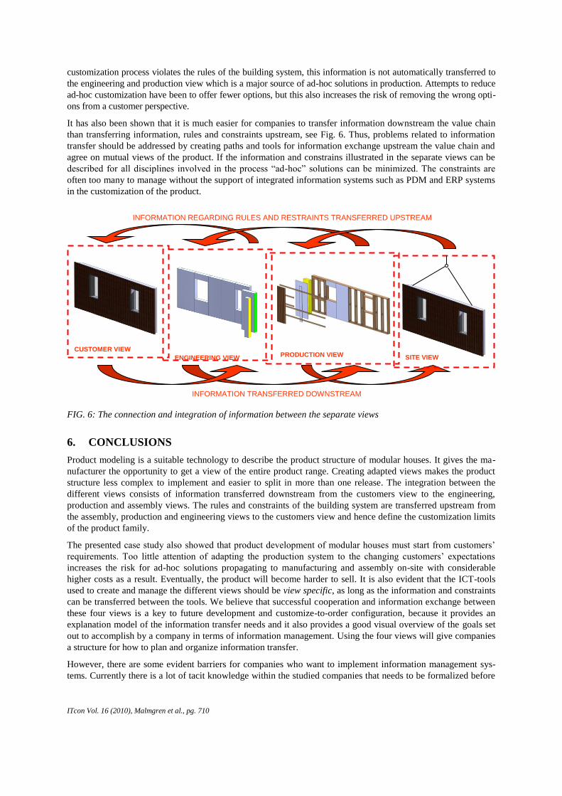
It has also been shown that it is much easier for companies to transfer information downstream the value chain
than transferring information, rules and constraints upstream, see Fig. 6. Thus, problems related to information
transfer should be addressed by creating paths and tools for information exchange upstream the value chain and
agree on mutual views of the product. If the information and constrains illustrated in the separate views can be
described for all disciplines involved in the process “ad-hoc” solutions can be minimized. The constraints are
often too many to manage without the support of integrated information systems such as PDM and ERP systems
in the customization of the product.
FIG. 6: The connection and integration of information between the separate views
6. CONCLUSIONS
Product modeling is a suitable technology to describe the product structure of modular houses. It gives the ma-
nufacturer the opportunity to get a view of the entire product range. Creating adapted views makes the product
structure less complex to implement and easier to split in more than one release. The integration between the
different views consists of information transferred downstream from the customers view to the engineering,
production and assembly views. The rules and constraints of the building system are transferred upstream from
the assembly, production and engineering views to the customers view and hence define the customization limits
of the product family.
The presented case study also showed that product development of modular houses must start from customers’
requirements. Too little attention of adapting the production system to the changing customers’ expectations
increases the risk for ad-hoc solutions propagating to manufacturing and assembly on-site with considerable
higher costs as a result. Eventually, the product will become harder to sell. It is also evident that the ICT-tools
used to create and manage the different views should be view specific, as long as the information and constraints
can be transferred between the tools. We believe that successful cooperation and information exchange between
these four views is a key to future development and customize-to-order configuration, because it provides an
explanation model of the information transfer needs and it also provides a good visual overview of the goals set
out to accomplish by a company in terms of information management. Using the four views will give companies
a structure for how to plan and organize information transfer.
However, there are some evident barriers for companies who want to implement information management sys-
tems. Currently there is a lot of tacit knowledge within the studied companies that needs to be formalized before
PRODUCTION VIEW ENGINEERING VIEW
CUSTOMER VIEW
SITE VIEW
INFORMATION REGARDING RULES AND RESTRAINTS TRANSFERRED UPSTREAM
INFORMATION TRANSFERRED DOWNSTREAM
ITcon Vol. 16 (2010), Malmgren et al., pg. 711
it can be used in an IT system. Several companies also need to go through a process of unifying their view on
product information within the company, so that they have a common ground to stand on when taking on new
challenges. Another issue is that the general level of IT maturity is lower compared to other industries.
Regarding the choice of system there are no specific systems for integrating information in this relatively small
sector, which means that custom development is one probable solution. Going forward companies need to be
prepared that regardless of what system they decide to use, it will probably need customization to work with
their specific needs and processes. This implies that the company has to be more involved in the development
or customization, the right competence for this might need to be built up before a project can be initialized.
The main lesson learned from the studied project is that it proved beneficial to use the presented four views as
a way of visualizing the information flow from customer requirements to a turnkey-ready house. This approach
also showed useful as an analysis model – by using the views to assess how well integrated information transfer
is achieved within a company. We have also learned that a mismatch between the technical platform and custo-
mer requirements will lead to more ad-hoc customization downstream, which in turn leads to a product platform
that might grow without control. Instead, new product features should be introduced as a result of strategic deci-
sions that are aligned with the overall company strategy.
ACKNOWLEDGEMENTS
The financial support of Tyréns AB and the Swedish Governmental Agency for Innovation Systems, VINNOVA, is
gratefully acknowledged. This work was performed within the competence centre Lean Wood Engineering at Luleå
University of Technology, Linköping Institute of Technology and Lund Institute of Technology, all in Sweden.
REFERENCES
Akao Y. 1990. Quality Function Deployment QFD, Integrating customer requirements into product design,
Productivity Press, New York, US.
Bertelsen S. 2005. Modularization –A Third Approach to Making Construction Lean?, in Proc. 13th Annual
Conference of the International Group for Lean Construction, Sydney, Australia.
Björk B-C. 1995. Requirements and information structures for building product data models, Doctoral disser-
tation, Technical Research Centre of Finland (VTT), Espoo, Finland.
Brege S. 2008. Presentation at the workshop for Lean wood engineering program, Dept. of Management and
Engineering, Linköping University, Linköping, March 2008.
BuildingSmart 2009. www.iai-tech.org, accessed on 2009-12-07.
Claesson A., Johannesson H. and Gedell S. 2001. Platform Product Development: Product Model a System
Structure Composed of Configurable Components, in Proc. DETC’01 / ASME 2001, Joint Design
Engineering Technical Conference and Computers and Information in Engineering Conference,
Pittsburgh, PA, Sept. 9-11, 2001.
Dikmen I., Birgonul M. T. and Kiziltas S. 2004. Strategic use of quality function deployment (QFD) in the con-
struction industry, Building and Environment, Vol. 40, No. 2, pp. 245-255, Pergamon.
Eldin N. and Hikle V. 2003. Pilot Study of Quality Function Deployment in Construction Projects, Journal of
construction engineering and management, Vol. 129, No. 3, pp. 314-329, ASCE.
Erixon G. 1998. Modular Function Deployment – A Method for Product Modularization, Ph.D. Thesis, Dept. of
Manufacturing Systems, Royal Institute of Technology, Stockholm.
Hofman E., Halman J.I.M. and Ion R.A. 2006. Variation in Housing Design: Identifying Customer Preferences,
Housing Studies, Vol. 21, No. 6, pp. 929–943.
Horsman W. M. 2008. Botrender 08, En rapport om framtidens boende (in Swedish), Tyréns AB, Stockholm.
Hvam L., Mortensen N. H. and Riis J. 2008. Product Customization, Springer-Verlag, Berlin Heidelberg.
IKEA 2009. www.ikea.se. Accessed on 2009-12-07.
ITcon Vol. 16 (2010), Malmgren et al., pg. 712
ISO 10303-11:2004. The EXPRESS language reference manual, http://www.iso.org.
Johnsson H., Malmgren L. and Persson S. 2007. ICT support for industrial production of houses – the Swedish
case, in Proc. CIB W78, Maribor, June 2007.
Johnsson H., Persson S., Malmgren L., Tarandi V. and Bremme J. 2006. IT-stöd för industriellt byggande i trä
(in Swedish) Technical report 2006:19, Div. of Structural Engineering, Luleå University of Technology,
Luleå, Sweden.
Jongeling R. and Olofsson T. 2007. A method for planning of work-flow by combined use of location-based
scheduling and 4D CAD, Automation in Construction, Vol. 16, No. 2, pp. 189-198, Elsevier.
Jørgensen K. A. 2001. Product configuration- Concepts and methodology, in Proc. 4th SMESME International
conference, Aalborg, May 2001.
Leckner T. and Lacher M. 2003. Simplifying configuration through customer oriented product models, Inter-
national conference on engineering design, ICED 03 Stockholm, August 2003.
Lee G., Sacks R. and Eastman C. 2007. Product data modeling using GTPPM – A case study, Automation in
Construction, Vol. 16, No. 3, pp. 392-407, Elsevier.
Nasereddin M., Mullens M.A. and Cope D. 2007. Automated simulator development: A strategy for modeling
modular housing production, Automation in Construction, Vol. 16, No.2, pp. 212-223, Elsevier.
Persson S., Malmgren L. and Johnsson H. 2009. Information management in industrial housing design and
manufacturing, ITcon Vol. 14, pp. 110-122.
Sandberg M., Johnsson H. and Larsson T. 2008. Knowledge-based engineering in construction: the prefabri-
cated timber housing case, ITcon Vol. 13, pp. 408-420.
Schenck D. and Wilson P. 1994. Information Modeling: The EXPRESS Way, Oxford University Press, NY.
Sudarsan R., Fenves S.J., Sriram R.D. and Wang F. 2005. A product information modeling framework for
product lifecycle management, Computer-Aided Design, Vol. 37, No. 13, pp. 1399-1412, Elsevier.
Vennstra V.S., Hallman J. I. M. and Voordijk J. T. 2006. A Methodology for Developing Product Platforms in
the Specific Setting of the House Building Industry, Research in engineering design, Vol. 17, No. 3, pp.
157-173, Springer-Verlag.
Yang D., Dong M. and Miao R. 2008. Development of a product configuration system with an ontology-based
approach, Computer-Aided Design, Vol. 40, No. 8, pp. 863-879, Elsevier.
![MPC8548E Configurable Development System … Configurable Development System Reference Manual, ... [4:0] ... MPC8548E Configurable Development System Reference Manual,](https://img.pdfslide.us/doc/110x75/5af028337f8b9ac62b8e4c0e/mpc8548e-configurable-development-system-configurable-development-system-reference.jpg)