Embed Size (px)
Citation preview
Product Line Architecture for a Family of Meshing
Tools
María Cecilia Bastarrica, Nancy Hitschfeld-Kahler, Pedro O. Rossel
Computer Science Department, Universidad de Chile{cecilia|nancy|prossel}@dcc.uchile.cl
Agenda Meshing Tools Software Product Lines Product Line Architecture Our Proposal: A Meshing Tool PLA Product Instantiation Future Work and Conclusions
Meshing Tools Meshing tools manage discretizations of
certain application domains. Independently of the application domain,
all meshing tools share functionality: Read the domain geometry and physical values Generate an initial mesh Refine, improve, derefine or smooth the mesh
according to a quality criterion Store the mesh into a file
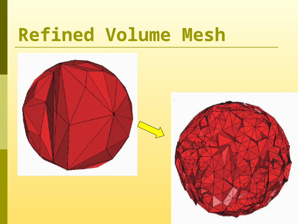
Refined Volume Mesh
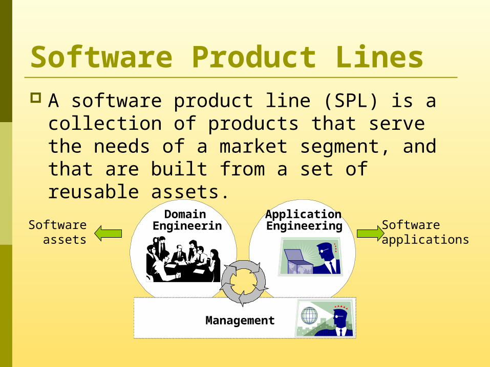
Software Product Lines A software product line (SPL) is a
collection of products that serve the needs of a market segment, and that are built from a set of reusable assets.
Management
DomainEngineering
ApplicationEngineering Software
applicationsSoftware
assets
Domain Engineering:Typical Reusable Assets Executable software components Software source code Reusable libraries Test sets and test cases
…and the Product Line Architecture
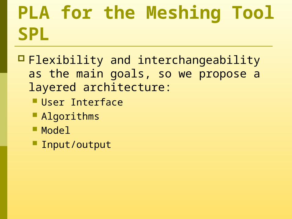
PLA for the Meshing Tool SPL Flexibility and interchangeability as the
main goals, so we propose a layered architecture: User Interface Algorithms Model Input/output
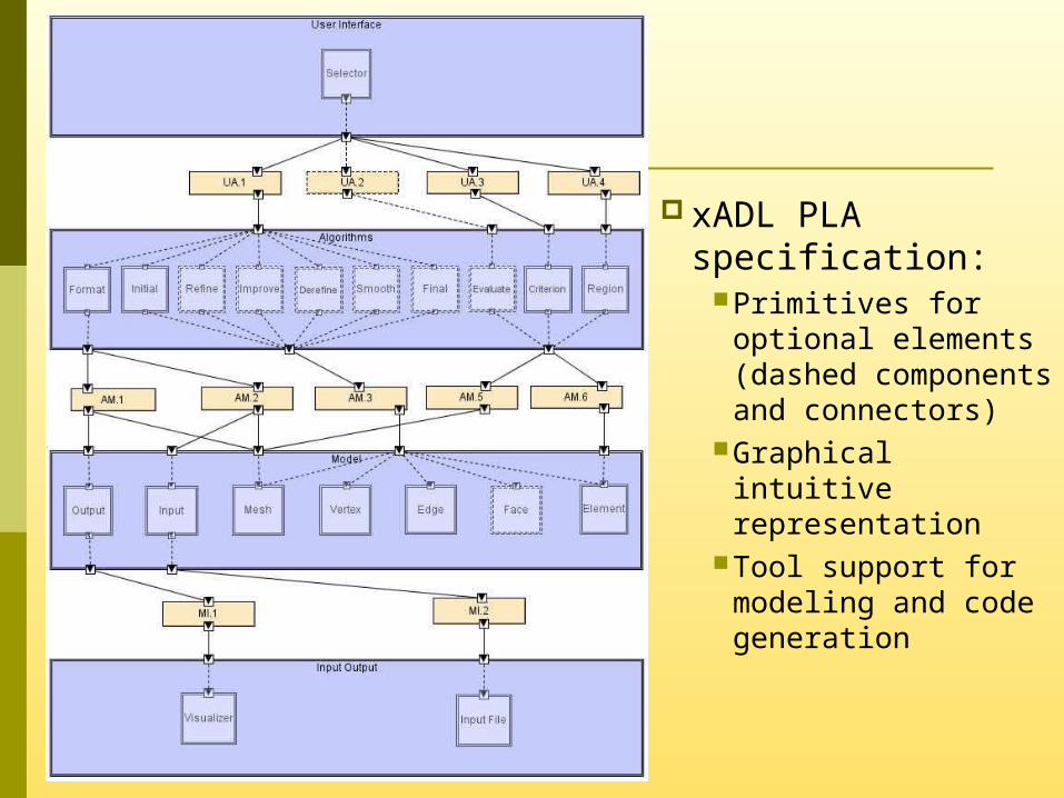
xADL PLA specification:
Primitives for optional elements (dashed components and connectors)
Graphical intuitive representation
Tool support for modeling and code generation
Application Engineering: Product Instantiation Generating products using the proposed
PLA implies two steps: Component type selection Implementation selection
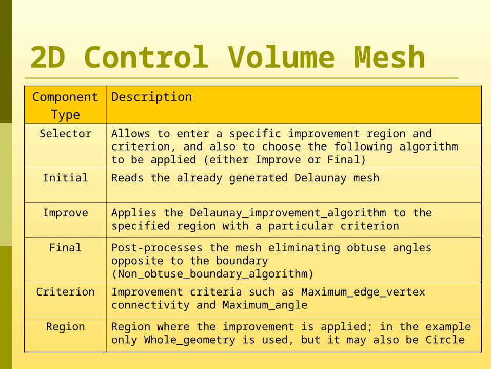
2D Control Volume MeshComponent
TypeDescription
Selector Allows to enter a specific improvement region and criterion, and also to choose the following algorithm to be applied (either Improve or Final)
Initial Reads the already generated Delaunay mesh
Improve Applies the Delaunay_improvement_algorithm to the specified region with a particular criterion
Final Post-processes the mesh eliminating obtuse angles opposite to the boundary (Non_obtuse_boundary_algorithm)
Criterion Improvement criteria such as Maximum_edge_vertex connectivity and Maximum_angle
Region Region where the improvement is applied; in the example only Whole_geometry is used, but it may also be Circle
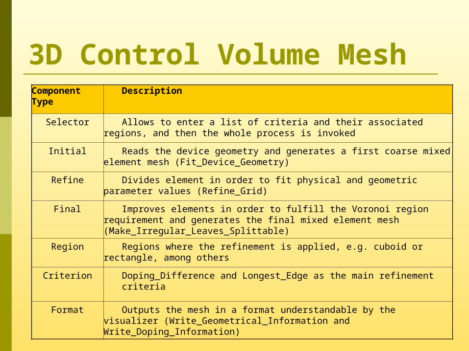
3D Control Volume MeshComponent Type
Description
Selector Allows to enter a list of criteria and their associated regions, and then the whole process is invoked
Initial Reads the device geometry and generates a first coarse mixed element mesh (Fit_Device_Geometry)
Refine Divides element in order to fit physical and geometric parameter values (Refine_Grid)
Final Improves elements in order to fulfill the Voronoi region requirement and generates the final mixed element mesh (Make_Irregular_Leaves_Splittable)
Region Regions where the refinement is applied, e.g. cuboid or rectangle, among others
Criterion Doping_Difference and Longest_Edge as the main refinement criteria
Format Outputs the mesh in a format understandable by the visualizer (Write_Geometrical_Information and Write_Doping_Information)
Conclusions SPL are specially suited for meshing tools Having a tested PLA helps defining new
family products Clearly defining the PLA brought multiple
benefits: Basis for communication Possibility of consistency analysis Potential for instance meshing tool generation
Conclusions (cont.) Formally defining the PLA makes it
possible to (semi) automate the process of instance tool generation: The PLA can be considered as a high
abstraction level model The component type selection is a model
transformation into another one where there are no optional elements
The implementation selection precisely determines which pieces of code form part of the specific tool
In a last transformation, all pieces are put together to generate the tool code
Work in Progress Refine the PLA definition so that it includes
all the guard conditions required for each transformation step.
Meshing tool component adaptation so that they comply with the interfaces defined by the PLA.
Implement a framework that supports all the tool generation process using MDE concepts.


![TheEffectsofSpectralPretreatmentsonChemometricAnalyses ...downloads.hindawi.com/journals/aess/2012/274903.pdfViscarra Rossel and Behrens [17]give a comprehensive comparison of many](https://img.pdfslide.us/doc/110x75/601c6ed03bb93d3cc1564338/theeffectsofspectralpretreatmentsonchemometricanalyses-viscarra-rossel-and-behrens.jpg)