Embed Size (px)
Citation preview
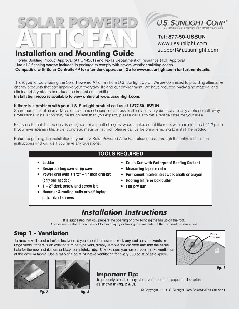
Installation and Mounting GuideFlorida Building Product Approval (# FL 14561) and Texas Department of Insurance (TDI) ApprovalUse all 8 flashing screws included in package to comply with severe weather building codes.Compatible with Solar Controller™ for after dark operation. Go to www.ussunlight.com for further details.
Thank you for purchasing the Solar Powered Attic Fan from U.S. Sunlight Corp. We are committed to providing alternative energy products that can improve your everyday life and our environment. We have reduced packaging material and eliminated Styrofoam to reduce the impact on landfills. Installation video is available to view online at www.ussunlight.com.
If there is a problem with your U.S. Sunlight product call us at 1-877-50-USSUNSpare parts, installation advice, or recommendations for professional installers in your area are only a phone call away. Professional installation may be much less than you expect, please call us to get average rates for your area.
Please note that this product is designed for asphalt shingles, wood shake, or flat tile roofs with a minimum of 4/12 pitch. If you have spanish tile, s-tile, concrete, metal or flat roof, please call us before attempting to install the product.
Before beginning the installation of your new Solar Powered Attic Fan, please read through the entire installation instructions and call us if you have any questions.
TOOLS REQUIRED
• Ladder• Reciprocating saw or jig saw • Power drill with a 1/2” – 1” inch drill bit (only one needed) • 1 – 2” deck screw and screw bit• Hammer & roofing nails or self taping galvanized screws
• Caulk Gun with Waterproof Roofing Sealant • Measuring tape or ruler• Permanent marker, sidewalk chalk or crayon• Roofing knife or box cutter• Flat pry bar
Installation InstructionsIt is suggested that you prepare the opening prior to bringing the fan up on the roof.
Always secure the fan on the roof to avoid injury or having the fan slide off the roof and get damaged.
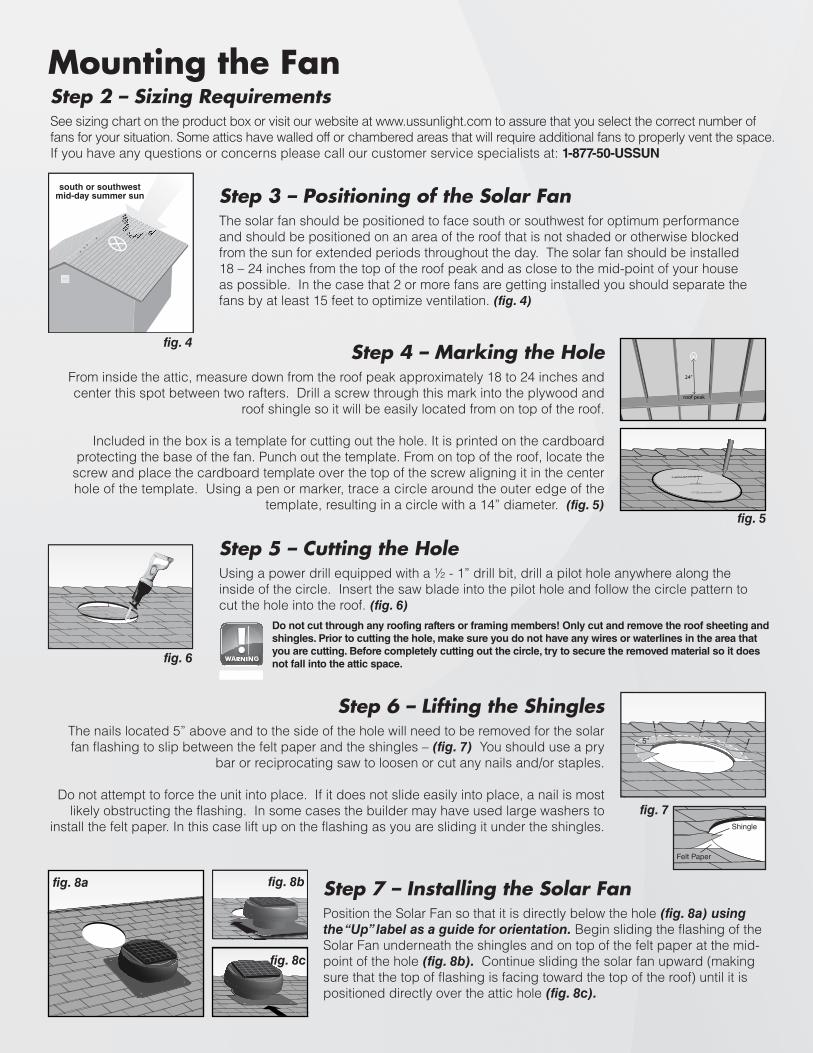
Step 1 - VentilationTo maximize the solar fan’s effectiveness you should remove or block any rooftop static vents or ridge vents. If there is an existing turbine type vent, simply remove the old vent and use the same hole for the new installation, or block completely. (fig. 1) Make sure you have proper intake ventilation at the eave or fascia. Use a ratio of 1 sq. ft. of intake ventilation for every 600 sq. ft. of attic space.
Important Tip: To properly close off any static vents, use tar paper and staples as shown in (fig. 2 & 3).
fig. 2 fig. 3
fig. 1
Tel: [email protected]
SOLAR POWERED
Block or Remove
© Copyright 2012 U.S. Sunlight Corp SolarAtticFan C01 ver 1
Mounting the FanStep 2 – Sizing Requirements
See sizing chart on the product box or visit our website at www.ussunlight.com to assure that you select the correct number of fans for your situation. Some attics have walled off or chambered areas that will require additional fans to properly vent the space. If you have any questions or concerns please call our customer service specialists at: 1-877-50-USSUN
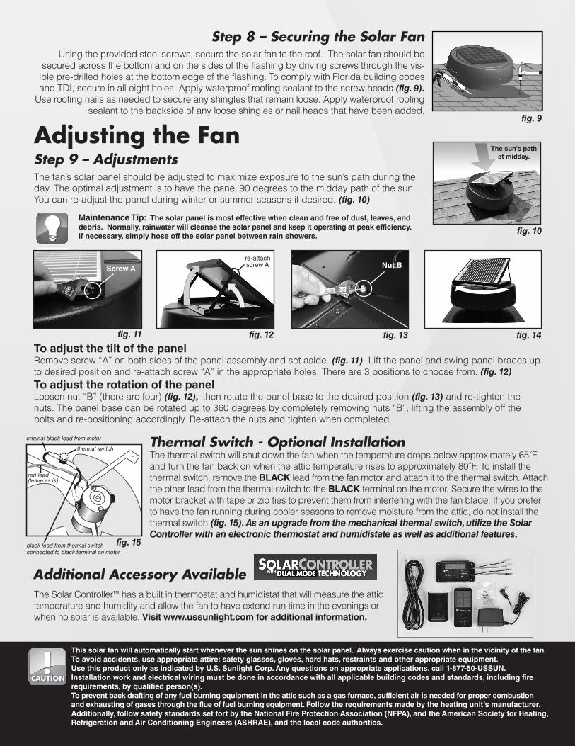
south or southwestmid-day summer sun Step 3 – Positioning of the Solar Fan
The solar fan should be positioned to face south or southwest for optimum performance and should be positioned on an area of the roof that is not shaded or otherwise blocked from the sun for extended periods throughout the day. The solar fan should be installed 18 – 24 inches from the top of the roof peak and as close to the mid-point of your house as possible. In the case that 2 or more fans are getting installed you should separate the fans by at least 15 feet to optimize ventilation. (fig. 4)
Step 4 – Marking the HoleFrom inside the attic, measure down from the roof peak approximately 18 to 24 inches and center this spot between two rafters. Drill a screw through this mark into the plywood and
roof shingle so it will be easily located from on top of the roof.
Included in the box is a template for cutting out the hole. It is printed on the cardboard protecting the base of the fan. Punch out the template. From on top of the roof, locate the
screw and place the cardboard template over the top of the screw aligning it in the center hole of the template. Using a pen or marker, trace a circle around the outer edge of the
template, resulting in a circle with a 14” diameter. (fig. 5)
fig. 4
fig. 5
Step 5 – Cutting the HoleUsing a power drill equipped with a ½ - 1” drill bit, drill a pilot hole anywhere along the inside of the circle. Insert the saw blade into the pilot hole and follow the circle pattern to cut the hole into the roof. (fig. 6)
fig. 6
Do not cut through any roofing rafters or framing members! Only cut and remove the roof sheeting and shingles. Prior to cutting the hole, make sure you do not have any wires or waterlines in the area that you are cutting. Before completely cutting out the circle, try to secure the removed material so it does not fall into the attic space.
5”
Shingle
Felt Paper
Step 6 – Lifting the Shingles The nails located 5” above and to the side of the hole will need to be removed for the solar fan flashing to slip between the felt paper and the shingles – (fig. 7) You should use a pry
bar or reciprocating saw to loosen or cut any nails and/or staples.
Do not attempt to force the unit into place. If it does not slide easily into place, a nail is most likely obstructing the flashing. In some cases the builder may have used large washers to
install the felt paper. In this case lift up on the flashing as you are sliding it under the shingles.fig. 7
24”
roof peak
Step 7 – Installing the Solar FanPosition the Solar Fan so that it is directly below the hole (fig. 8a) using the “Up” label as a guide for orientation. Begin sliding the flashing of the Solar Fan underneath the shingles and on top of the felt paper at the mid-point of the hole (fig. 8b). Continue sliding the solar fan upward (making sure that the top of flashing is facing toward the top of the roof) until it is positioned directly over the attic hole (fig. 8c).
fig. 8a fig. 8b
fig. 8c
Step 8 – Securing the Solar FanUsing the provided steel screws, secure the solar fan to the roof. The solar fan should be
secured across the bottom and on the sides of the flashing by driving screws through the vis-ible pre-drilled holes at the bottom edge of the flashing. To comply with Florida building codes and TDI, secure in all eight holes. Apply waterproof roofing sealant to the screw heads (fig. 9).
Use roofing nails as needed to secure any shingles that remain loose. Apply waterproof roofing sealant to the backside of any loose shingles or nail heads that have been added.
fig. 9
Maintenance Tip: The solar panel is most effective when clean and free of dust, leaves, and debris. Normally, rainwater will cleanse the solar panel and keep it operating at peak efficiency. If necessary, simply hose off the solar panel between rain showers.
Adjusting the FanStep 9 – AdjustmentsThe fan’s solar panel should be adjusted to maximize exposure to the sun’s path during the day. The optimal adjustment is to have the panel 90 degrees to the midday path of the sun. You can re-adjust the panel during winter or summer seasons if desired. (fig. 10)
To adjust the tilt of the panelRemove screw “A” on both sides of the panel assembly and set aside. (fig. 11) Lift the panel and swing panel braces up to desired position and re-attach screw “A” in the appropriate holes. There are 3 positions to choose from. (fig. 12)
To adjust the rotation of the panelLoosen nut “B” (there are four) (fig. 12), then rotate the panel base to the desired position (fig. 13) and re-tighten the nuts. The panel base can be rotated up to 360 degrees by completely removing nuts “B”, lifting the assembly off the bolts and re-positioning accordingly. Re-attach the nuts and tighten when completed.
The sun’s path at midday.
fig. 10
fig. 11 fig. 12 fig. 13 fig. 14
re-attachscrew AScrew A Nut B
Additional Accessory AvailableThe Solar Controller™ has a built in thermostat and humidistat that will measure the attic temperature and humidity and allow the fan to have extend run time in the evenings or when no solar is available. Visit www.ussunlight.com for additional information.
™
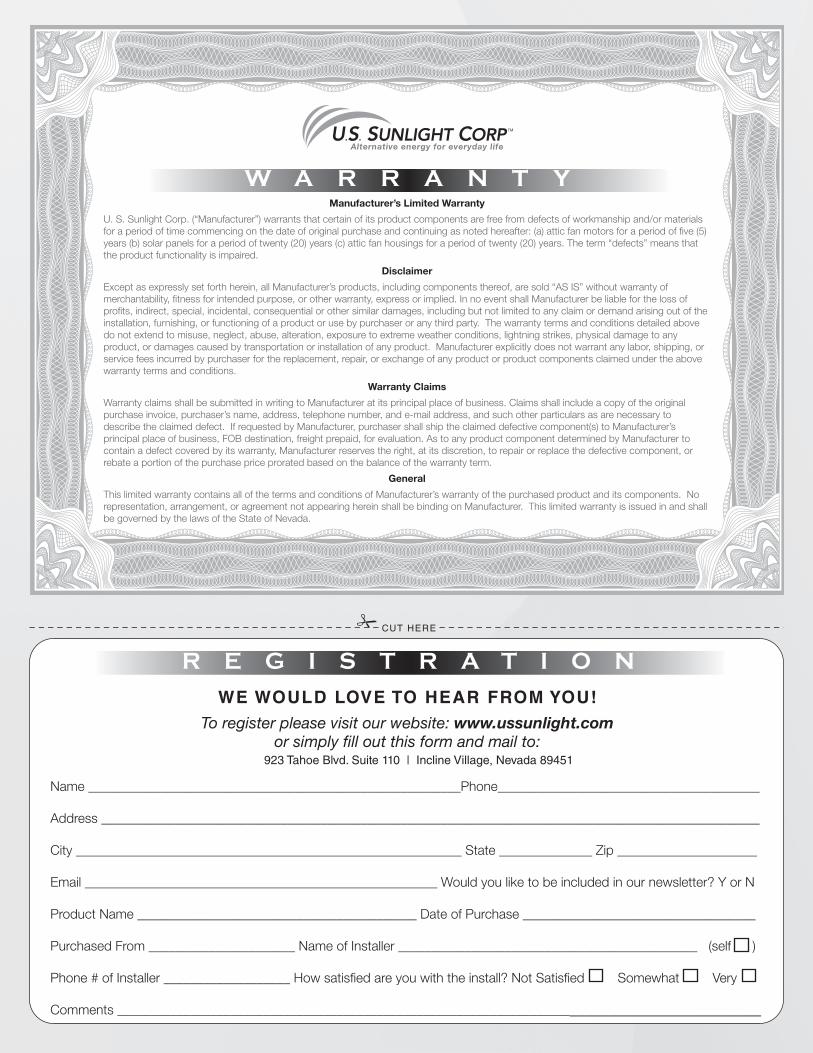
Thermal Switch - Optional InstallationThe thermal switch will shut down the fan when the temperature drops below approximately 65˚F and turn the fan back on when the attic temperature rises to approximately 80˚F. To install the thermal switch, remove the BLACK lead from the fan motor and attach it to the thermal switch. Attach the other lead from the thermal switch to the BLACK terminal on the motor. Secure the wires to the motor bracket with tape or zip ties to prevent them from interfering with the fan blade. If you prefer to have the fan running during cooler seasons to remove moisture from the attic, do not install the thermal switch (fig. 15). As an upgrade from the mechanical thermal switch, utilize the Solar Controller with an electronic thermostat and humidistate as well as additional features.
thermal switch
red lead(leave as is)
black lead from thermal switchconnected to black terminal on motor
original black lead from motor
fig. 15
This solar fan will automatically start whenever the sun shines on the solar panel. Always exercise caution when in the vicinity of the fan.To avoid accidents, use appropriate attire: safety glasses, gloves, hard hats, restraints and other appropriate equipment.Use this product only as indicated by U.S. Sunlight Corp. Any questions on appropriate applications, call 1-877-50-USSUN.Installation work and electrical wiring must be done in accordance with all applicable building codes and standards, including fire requirements, by qualified person(s).To prevent back drafting of any fuel burning equipment in the attic such as a gas furnace, sufficient air is needed for proper combustion and exhausting of gases through the flue of fuel burning equipment. Follow the requirements made by the heating unit’s manufacturer. Additionally, follow safety standards set fort by the National Fire Protection Association (NFPA), and the American Society for Heating, Refrigeration and Air Conditioning Engineers (ASHRAE), and the local code authorities.
Manufacturer’s Limited Warranty
U. S. Sunlight Corp. (“Manufacturer”) warrants that certain of its product components are free from defects of workmanship and/or materialsfor a period of time commencing on the date of original purchase and continuing as noted hereafter: (a) attic fan motors for a period of �ve (5) years (b) solar panels for a period of twenty (20) years (c) attic fan housings for a period of twenty (20) years. The term “defects” means that the product functionality is impaired.
Disclaimer
Except as expressly set forth herein, all Manufacturer’s products, including components thereof, are sold “AS IS” without warranty ofmerchantability, �tness for intended purpose, or other warranty, express or implied. In no event shall Manufacturer be liable for the loss of pro�ts, indirect, special, incidental, consequential or other similar damages, including but not limited to any claim or demand arising out of the installation, furnishing, or functioning of a product or use by purchaser or any third party. The warranty terms and conditions detailed above do not extend to misuse, neglect, abuse, alteration, exposure to extreme weather conditions, lightning strikes, physical damage to any product, or damages caused by transportation or installation of any product. Manufacturer explicitly does not warrant any labor, shipping, or service fees incurred by purchaser for the replacement, repair, or exchange of any product or product components claimed under the above warranty terms and conditions.
Warranty Claims
Warranty claims shall be submitted in writing to Manufacturer at its principal place of business. Claims shall include a copy of the originalpurchase invoice, purchaser’s name, address, telephone number, and e-mail address, and such other particulars as are necessary to describe the claimed defect. If requested by Manufacturer, purchaser shall ship the claimed defective component(s) to Manufacturer’s principal place of business, FOB destination, freight prepaid, for evaluation. As to any product component determined by Manufacturer to contain a defect covered by its warranty, Manufacturer reserves the right, at its discretion, to repair or replace the defective component, or rebate a portion of the purchase price prorated based on the balance of the warranty term.
General
This limited warranty contains all of the terms and conditions of Manufacturer’s warranty of the purchased product and its components. Norepresentation, arrangement, or agreement not appearing herein shall be binding on Manufacturer. This limited warranty is issued in and shall be governed by the laws of the State of Nevada.
W A R R A N T Y
CUT HERE
R E G I S T R A T I O N
WE WOULD LOVE TO HEAR FROM YOU!To register please visit our website: www.ussunlight.com
or simply �ll out this form and mail to:
Name ________________________________________________________Phone________________________________________
Address ___________________________________________________________________________________________________
City __________________________________________________________ State ______________ Zip _____________________
Email _____________________________________________________ Would you like to be included in our newsletter? Y or N
Product Name __________________________________________ Date of Purchase ___________________________________
Purchased From ______________________ Name of Installer _____________________________________________ (self )
Phone # of Installer ___________________ How satis�ed are you with the install? Not Satis�ed Somewhat Very
Comments ____________________________________________________________________________________________
923 Tahoe Blvd. Suite 110 | Incline Village, Nevada 89451