Embed Size (px)
Citation preview
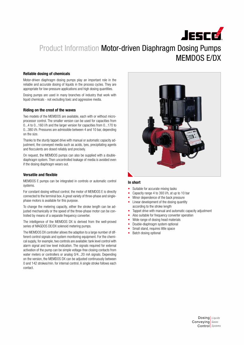
Reliable dosing of chemicalsMotor-driven diaphragm dosing pumps play an important role in the reliable and accurate dosing of liquids in the process cycles. They are appropriate for low-pressure applications and high dosing quantities.
Dosing pumps are used in many branches of industry that work with liquid chemicals - not excluding toxic and aggressive media.
Riding on the crest of the wavesTwo models of the MEMDOS are available, each with or without micro-processor control. The smaller version can be used for capacities from 0...4 to 0...160 l/h and the larger version for capacities from 0...170 to 0...380 l/h. Pressures are admissible between 4 and 10 bar, depending on the size.
Thanks to the sturdy tappet drive with manual or automatic capacity ad-justment, the conveyed media such as acids, lyes, precipitating agents and flocculents are dosed reliably and precisely.
On request, the MEMDOS pumps can also be supplied with a double-diaphragm system. Then uncontrolled leakage of media is avoided even if the dosing diaphragm wears out.
Versatile and flexibleMEMDOS E pumps can be integrated in controls or automatic control systems.
For constant dosing without control, the motor of MEMDOS E is directly connected to the terminal box. A great variety of three-phase and single-phase motors is available for this purpose.
To change the metering capacity, either the stroke length can be ad-justed mechanically or the speed of the three-phase motor can be con-trolled by means of a separate frequency converter.
The intelligence of the MEMDOS DX is derived from the well-proved series of MAGDOS DE/DX solenoid metering pumps.
The MEMDOS DX controller allows the adaption to a large number of dif-ferent control signals and system monitoring equipment. For the chemi-cal supply, for example, two controls are available: tank level control with alarm signal and low level indication. The signals required for external activation of the pump can be simple voltage-free closing contacts from water meters or controllers or analog 0/4...20 mA signals. Depending on the version, the MEMDOS DX can be adjusted continuously between 0 and 142 strokes/min. for internal control. A single stroke follows each contact.
Product Information Motor-driven Diaphragm Dosing Pumps MEMDOS E/DX
In short• Suitable for accurate mixing tasks• Capacity range 4 to 393 l/h, at up to 10 bar• Minor dependence of the back pressure• Linear development of the dosing quantity
according to the stroke length• Tappet drive with manual and automatic capacity adjustment• Also suitable for frequency converter operation• Wide range of dosing head materials• Double-diaphragm system optional• Small stand, requires little space• Batch dosing optional
DosingConveying
Control
Liquids
Gases
Systems
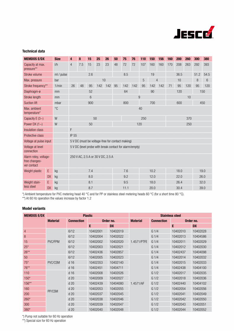
Technical data
MEMDOS E/DX Size 4 8 15 25 26 50 75 76 110 150 156 160 200 260 300 380Capacity at max. pressure**
l/h 4 7.5 15 23 23 48 72 72 107 160 160 170 208 263 292 393
Stroke volume ml / pulse 2.6 8.5 19 36.5 51.2 54.5
Max. pressure bar 10 5 4 10 8 6
Stroke frequency** 1/min 26 48 95 142 142 95 142 142 95 142 142 71 95 120 95 120
Diaphragm-ø mm 52 64 90 120 150
Stroke length mm 6 9 10
Suction lift mbar 900 800 700 600 450
Max. ambient temperature*
°C 40
Capacity E (3~) W 50 250 370
Power DX (1~) W 50 120 250
Insulation class F
Protective class IP 55
Voltage at pulse input 5 V DC (must be voltage-free for contact making)
Voltage at level connection
5 V DC (level probe with break contact for alarm/empty)
Alarm reley, voltage- free changeo-ver contact
250 V AC, 2.5 A or 30 V DC, 2.5 A
Weight plastic E kg 7.4 7.6 10.2 18.0 19.0
DX kg 8.0 9.2 12.0 22.0 26.0
Weight stain-less steel
E kg 8.1 9.5 18.0 26.4 32.0
DX kg 8.7 11.1 20.0 30.4 39.0
*) Ambient temperature for PVC metering head 40 °C and for PP or stainless steel metering heads 60 °C (for a short time 80 °C). **) At 60 Hz operation the values increase by factor 1.2
Model variantsMEMDOS E/DX Plastic Stainless steel
Material Connection Order no. Material Connection Order no.E DX E DX
4
PVC/FPM
6/12 10402001 10402019
1.4571/PTFE
G 1/4 10402010 10402028
8 6/12 10402004 10402022 G 1/4 10402013 10404586
15 6/12 10402002 10402020 G 1/4 10402011 10402029
25* 6/12 10402003 10402021 G 1/4 10402012 10402030
26** 6/12 10402436 10402857 G 1/4 10402437 10404098
50
PVC/CSM
6/12 10402005 10402023
1.4571/AF
G 1/4 10402014 10402032
75* d 16 10402353 10402140 G 1/4 10402015 10402033
76** d 16 10402451 10404711 G 1/4 10402438 10404100
110
PP/CSM
d 16 10402008 10402026 G 1/2 10402017 10402035
150* d 20 10402009 10402027 G 1/2 10402018 10402036
156** d 20 10402439 10404080 G 1/2 10402440 10404102
160 d 20 10402053 10402055 G 1/2 10402054 10402056
200 d 20 10402037 10402045 G 1/2 10402041 10402049
260* d 20 10402038 10402046 G 1/2 10402042 10402050
300 d 20 10402039 10402047 G 1/2 10402043 10402051
380* d 20 10402040 10402048 G 1/2 10402044 10402052
*) Pump not suitable for 60 Hz operation **) Special size for 60 Hz operation
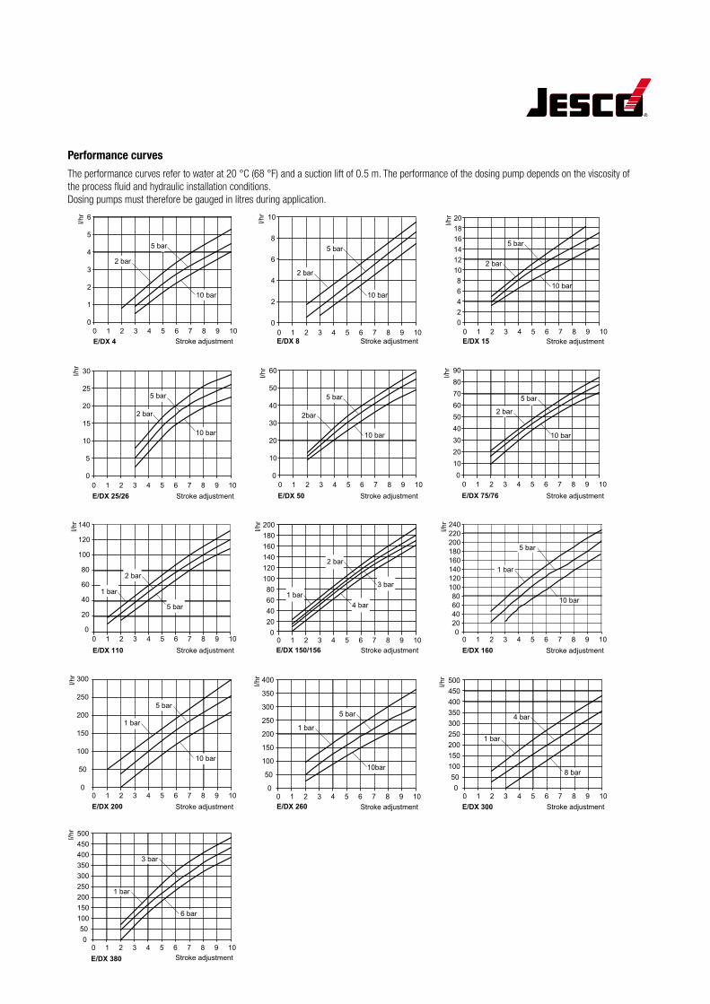
Performance curvesThe performance curves refer to water at 20 °C (68 °F) and a suction lift of 0.5 m. The performance of the dosing pump depends on the viscosity of the process fluid and hydraulic installation conditions. Dosing pumps must therefore be gauged in litres during application.
E/DX 4
0
1
2
3
4
5
6
0 1 2 3 4 5 6 7 8 9 10Stroke adjustment
l/hr
E/DX 8
0
2
4
6
8
10
0 1 2 3 4 5 6 7 8 9 10Stroke adjustment
l/hr
E/DX 15
02468
101214161820
0 1 2 3 4 5 6 7 8 9 10Stroke adjustment
l/hr
E/DX 25/26
0
5
10
15
20
25
30
0 1 2 3 4 5 6 7 8 9 10Stroke adjustment
l/hr
E/DX 50
0
10
20
30
40
50
60
0 1 2 3 4 5 6 7 8 9 10Stroke adjustment
l/hr
E/DX 75/76
0102030405060708090
0 1 2 3 4 5 6 7 8 9 10Stroke adjustment
l/hr
2bar
5 bar
10 bar
2 bar
5 bar
10 bar
2 bar
5 bar
10 bar
2 bar
5 bar
10 bar
2 bar
5 bar
10 bar
2 bar
5 bar
10 bar
E/DX 110
0
20
40
60
80
100
120
140
0 1 2 3 4 5 6 7 8 9 10Stroke adjustment
l/hr
E/DX 150/156
020406080
100120140160180200
0 1 2 3 4 5 6 7 8 9 10Stroke adjustment
l/hr
2 bar
E/DX 200
0
50
100
150
200
250
300
0 1 2 3 4 5 6 7 8 9 10Stroke adjustment
l/hr
E/DX 260
0
50
100
150
200
250
300
350
400
0 1 2 3 4 5 6 7 8 9 10Stroke adjustment
l/hr
E/DX 300
050
100150200250300350400450500
0 1 2 3 4 5 6 7 8 9 10Stroke adjustment
l/hr
E/DX 380
050
100150200250300350400450500
0 1 2 3 4 5 6 7 8 9 10Stroke adjustment
l/hr
1 bar3 bar
4 bar
2 bar
1 bar
5 bar
1 bar
5 bar
10 bar
1 bar
5 bar
10bar
1 bar
4 bar
8 bar
1 bar
3 bar
6 bar
020406080
100120140160180200220240
0 1 2 3 4 5 6 7 8 9 10Stroke adjustment
1 bar
10 bar
5 bar
l/hr
E/DX 160
Product Information Motor-driven Diaphragm Dosing Pumps MEMDOS E/DX
Lutz-Jesco GmbH P.O. Box 10 01 6430891 Wedemark
Phone: +49 5130 5802-0Fax: +49 5130 580268
E-mail: [email protected]: www.lutz-jesco.de
24h-Hotline:+49 5130 580280
PI-1
0402
-02-
V04
| C
opyr
ight
07.
2010
by
Lutz
-Jes
co G
mbH
Subj
ect t
o te
chni
cal c
hang
es
AccessoriesEven the best dosing pump is capable of improvement - by means of appropriate technical surroundings. That is why a particularly compre-hensive accessories programme is available which turns your dosing pump into an efficient dosing system.
As an option, the multifunctional valve PENTABLOC is available, which offers the functionalities of a back-pressure valve as well as those of a safety blowdown valve. Such functions as anti-siphon, pressure relief and flow indication and monitoring are also integrated.
For further accessories for your dosing pump, please refer to our dosing pump brochure.
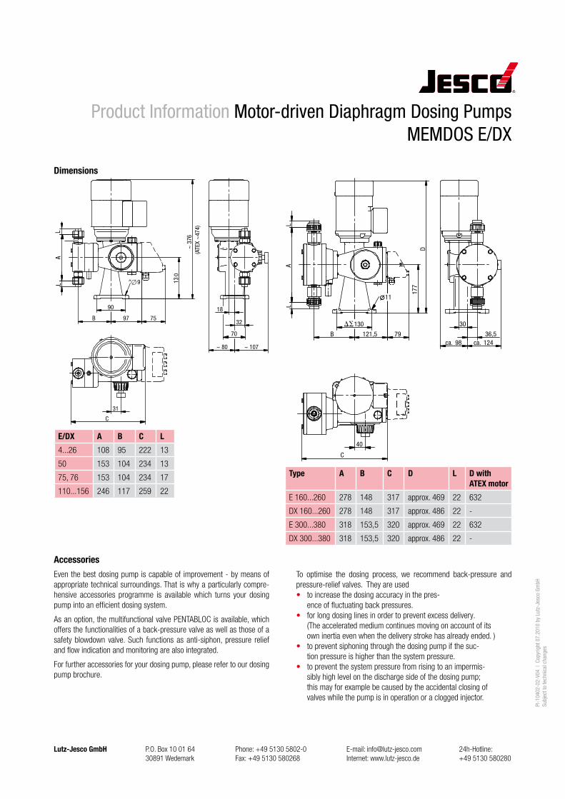
Dimensions
90
75
31
C
9 130
~ 3
76
B 9718
32
70
~ 80 ~ 107
LA
L
(ATE
X ~
474)
B98ca.
36,5
30
40
177
121,5
130
C
D
79124ca.
LA
L
11
E/DX A B C L4...26 108 95 222 13
50 153 104 234 13
75, 76 153 104 234 17
110...156 246 117 259 22
Type A B C D L D with ATEX motor
E 160...260 278 148 317 approx. 469 22 632
DX 160...260 278 148 317 approx. 486 22 -
E 300...380 318 153,5 320 approx. 469 22 632
DX 300...380 318 153,5 320 approx. 486 22 -
To optimise the dosing process, we recommend back-pressure and pressure-relief valves. They are used• to increase the dosing accuracy in the pres-
ence of fluctuating back pressures.• for long dosing lines in order to prevent excess delivery.
(The accelerated medium continues moving on account of its own inertia even when the delivery stroke has already ended. )
• to prevent siphoning through the dosing pump if the suc-tion pressure is higher than the system pressure.
• to prevent the system pressure from rising to an impermis-sibly high level on the discharge side of the dosing pump; this may for example be caused by the accidental closing of valves while the pump is in operation or a clogged injector.
ME
MD
OS
GM
R
MB 1 06 01 / 1
GeneralDouble diaphragm metering pumps of the Memdos GMRseries can be supplied as single or duplex meteringpumps. The pumps are used to meter large quantities atrelatively low back pressures. They are frequently usedin waste-water treatment to meter pH-regulatingchemicals or flocculents. The metering pumps areavailable in three sizes as single metering pumps for 2000to 4000 l/h. Different metering heads can be connectedto the duplex metering pumps. The metering heads arethen operating in a reciprocating mode and the quantitymetered is set for both heads at the same time.
DesignsStandard designs are: Single metering pump with left-hand metering head arangement.Type designation GMR Symbol
Duplex metering pumps with two metering heads.Type designation ZGMR Symbol
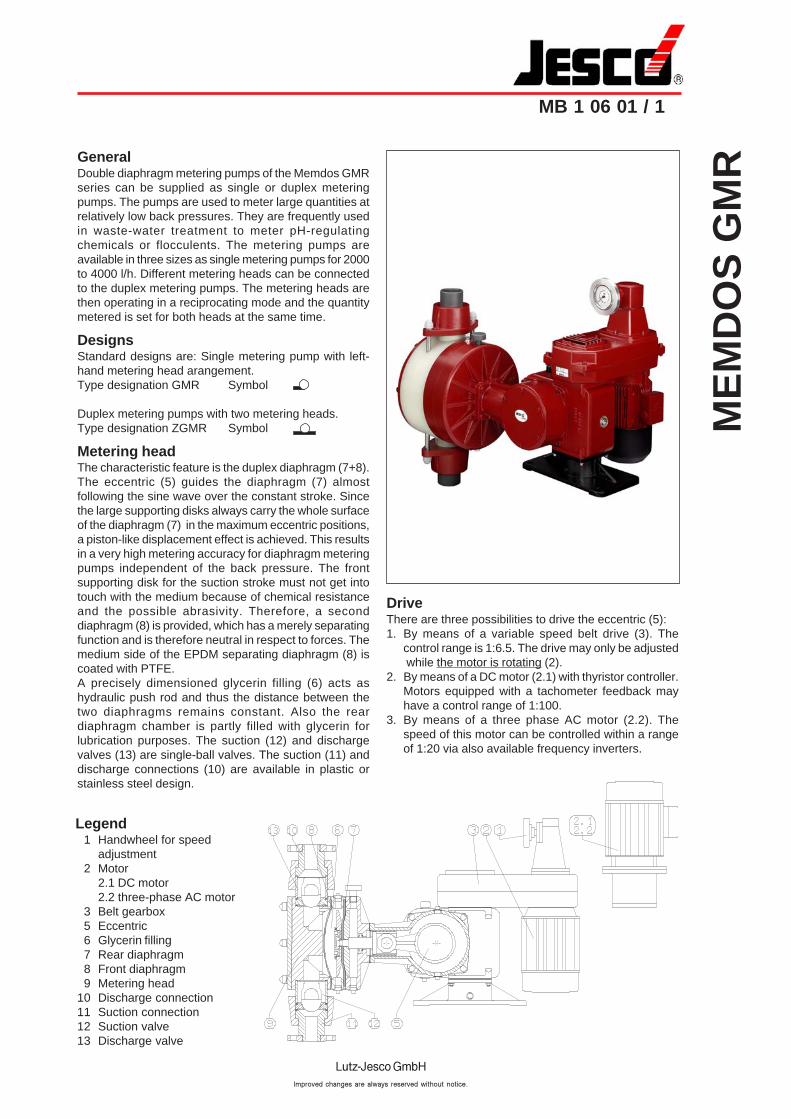
Metering headThe characteristic feature is the duplex diaphragm (7+8).The eccentric (5) guides the diaphragm (7) almostfollowing the sine wave over the constant stroke. Sincethe large supporting disks always carry the whole surfaceof the diaphragm (7) in the maximum eccentric positions,a piston-like displacement effect is achieved. This resultsin a very high metering accuracy for diaphragm meteringpumps independent of the back pressure. The frontsupporting disk for the suction stroke must not get intotouch with the medium because of chemical resistanceand the possible abrasivity. Therefore, a seconddiaphragm (8) is provided, which has a merely separatingfunction and is therefore neutral in respect to forces. Themedium side of the EPDM separating diaphragm (8) iscoated with PTFE.A precisely dimensioned glycerin filling (6) acts ashydraulic push rod and thus the distance between thetwo diaphragms remains constant. Also the reardiaphragm chamber is partly filled with glycerin forlubrication purposes. The suction (12) and dischargevalves (13) are single-ball valves. The suction (11) anddischarge connections (10) are available in plastic orstainless steel design.
DriveThere are three possibilities to drive the eccentric (5):1. By means of a variable speed belt drive (3). The
control range is 1:6.5. The drive may only be adjusted while the motor is rotating (2).
2. By means of a DC motor (2.1) with thyristor controller.Motors equipped with a tachometer feedback mayhave a control range of 1:100.
3. By means of a three phase AC motor (2.2). Thespeed of this motor can be controlled within a rangeof 1:20 via also available frequency inverters.
Legend1 Handwheel for speed
adjustment2 Motor
2.1 DC motor2.2 three-phase AC motor
3 Belt gearbox5 Eccentric6 Glycerin filling7 Rear diaphragm8 Front diaphragm9 Metering head
10 Discharge connection11 Suction connection12 Suction valve13 Discharge valve
ME
MD
OS
GM
R
MB 1 06 01 / 2
Additional componentsUpon request, the Memdos GMR can be equipped withan inductive probe which samples the crankshaft to countthe strokes. For diaphragm rupture detection, the frontglycerin chamber can be monitored by means of aconductivity probe.A reversible servomotor can be supplied for the gearboxadjustment which is required for the remote control ofthe metered quantity or for a process-dependent open-loop or closed-loop control, with the GMR acting as finalcontrol element. The actual speed, and thus the meteredquantity, is proportionally converted into an analog directvoltage signal by means of a tachogenerator.The signal can be directly transmitted to indicators. For
operation in control mode, the signal must be amplifiede.g. 0-20 mA.ImportantEnsure that control circuits are connected such that theautomatic stroke adjustment only works when the drivemotor is rotating.Upon request, a variable d.c. main drive is availableinstead of the variable speed belt drive. This can beadjusted from 0 to 100%. The motor is controlled via athyristor controller. The speed is remotely indicated bymeans of a tachometer or an I x R compensation.
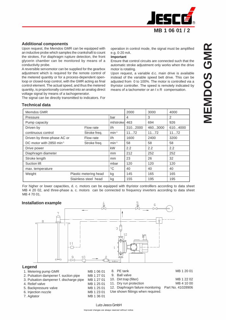
Installation example
Legend1. Metering pump GMR MB 1 06 012. Pulsation dampener f. suction pipe MB 1 27 013. Pulsation dampener f. discharge pipe MB 1 27 014. Relief valve MB 1 25 015. Backpressure valve MB 1 25 016. Injection nozzle MB 1 23 017. Agitator MB 1 36 01
8. PE tank MB 1 20 019. Ball valve
10. Dirt trap (filter) MB 1 22 0211. Dry run protection MB 4 10 0012. Diaphragm failure monitoring Part No. 41028906Use shown fittings when required.
Technical data
Memdos GMR 2000 3000 4000
Pressure bar 4 3 2
Pump capacity ml/stroke 463 694 926
Driven by Flow rate l/h 310...2000 460...3000 610...4000
continuous control Stroke freq. min-1 11...72 11...72 11...72
Driven by three-phase AC or Flow rate l/h 1600 2400 3200
DC motor with 2850 min-1 Stroke freq. min-1 58 58 58
Drive power kW 2.2 2.2 2.2
Diaphragm diameter mm 212 252 252
Stroke length mm 23 26 32
Suction lift mbar 120 120 120
max. temperature °C 40 40 40
Weight Plastic metering head kg 145 165 165
Stainless steel head kg 155 195 195
For higher or lower capacities, d. c. motors can be equipped with thyristor controlllers according to data sheetMB 4 20 02, and three-phase a. c. motors can be connected to frequency inverters according to data sheetMB 4 70 01.
ME
MD
OS
GM
R
MB 1 06 01 / 3
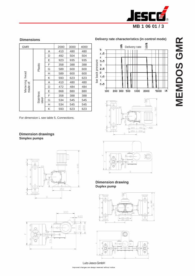
Delivery rate characteristics (in control mode)Dimensions
GMR 2000 3000 4000
A 410 480 480
D 492 504 504
E 923 935 935
F 358 388 388
G 589 600 600
H 589 600 600
K 593 623 623
A 410 480 480
D 472 484 484
E 868 880 880
F 358 388 388
G 534 545 545
H 534 545 545
K 593 623 623
For dimension L see table 5, Connections.
Me
teri
ng
he
ad
mad
e of
:
Pla
stic
Sta
inle
ssst
eel
Dimension drawingsSimplex pumps
Dimension drawingDuplex pump
Delivery rate
bar
back
pre
ssur
e
ME
MD
OS
GM
R
MB 1 06 01 / 4
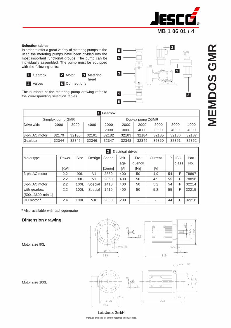
Selection tablesIn order to offer a great variety of metering pumps to theuser, the metering pumps have been divided into themost important functional groups. The pump can beindividually assembled. The pump must be equippedwith the following units:
Gearbox Motor Meteringhead
Valves Connections
The numbers at the metering pump drawing refer tothe corresponding selection tables.
Gearbox
Simplex pump GMR Duplex pump ZGMR
Drive with: 2000 3000 4000 2000 2000 2000 3000 3000 4000
2000 3000 4000 3000 4000 4000
3-ph. AC motor 32179 32180 32181 32182 32183 32184 32185 32186 32187
Gearbox 32344 32345 32346 32347 32348 32349 32350 32351 32352
Electrical drives
Motor type Power Size Design Speed Volt- Fre- Current IP ISO- Part
age quency class No.
[kW] [1/min] [V] [Hz] [A]
3-ph. AC motor 2.2 90L V1 2850 400 50 4.9 54 F 78897
2.2 90L V1 2850 400 50 4.9 55 F 78898
3-ph. AC motor 2.2 100L Special 1410 400 50 5.2 54 F 32214
with gearbox 2.2 100L Special 1410 400 50 5.2 55 F 32215
(500...3600 min-1)
DC motor * 2.4 100L V18 2850 200 - - 44 F 32218
* Also available with tachogenerator
1
2
Dimension drawing
Motor size 90L
Motor size 100L
1
4
2
5
3
5
3
4
4
2
1
5
2
ME
MD
OS
GM
R
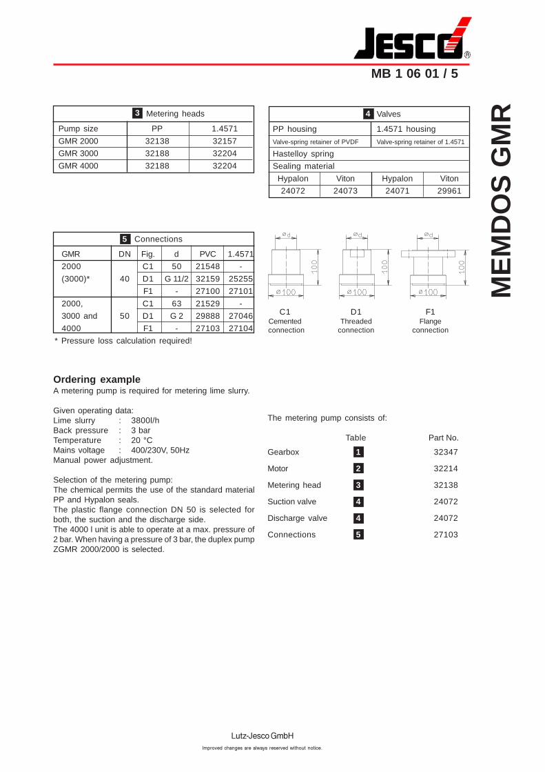
MB 1 06 01 / 5
Valves
PP housing 1.4571 housing
Valve-spring retainer of PVDF Valve-spring retainer of 1.4571
Hastelloy spring
Sealing material
Hypalon Viton Hypalon Viton
24072 24073 24071 29961
Metering heads
Pump size PP 1.4571
GMR 2000 32138 32157
GMR 3000 32188 32204
GMR 4000 32188 32204
Connections
GMR DN Fig. d PVC 1.4571
2000 C1 50 21548 -
(3000)* 40 D1 G 11/2 32159 25255
F1 - 27100 27101
2000, C1 63 21529 -
3000 and 50 D1 G 2 29888 27046
4000 F1 - 27103 27104
* Pressure loss calculation required!
Ordering exampleA metering pump is required for metering lime slurry.
Given operating data:Lime slurry : 3800l/hBack pressure : 3 barTemperature : 20 °CMains voltage : 400/230V, 50HzManual power adjustment.
Selection of the metering pump:The chemical permits the use of the standard materialPP and Hypalon seals.The plastic flange connection DN 50 is selected forboth, the suction and the discharge side.The 4000 l unit is able to operate at a max. pressure of2 bar. When having a pressure of 3 bar, the duplex pumpZGMR 2000/2000 is selected.
The metering pump consists of:
Table Part No.
Gearbox 1 32347
Motor 2 32214
Metering head 3 32138
Suction valve 4 24072
Discharge valve 4 24072
Connections 5 27103
4
C1 D1 F1Cemented Threaded Flangeconnection connection connection
5
3
Dia
ph
rag
m m
eter
ing
pu
mp
ME
MD
OS
MR
MB 1 05 02 / 1
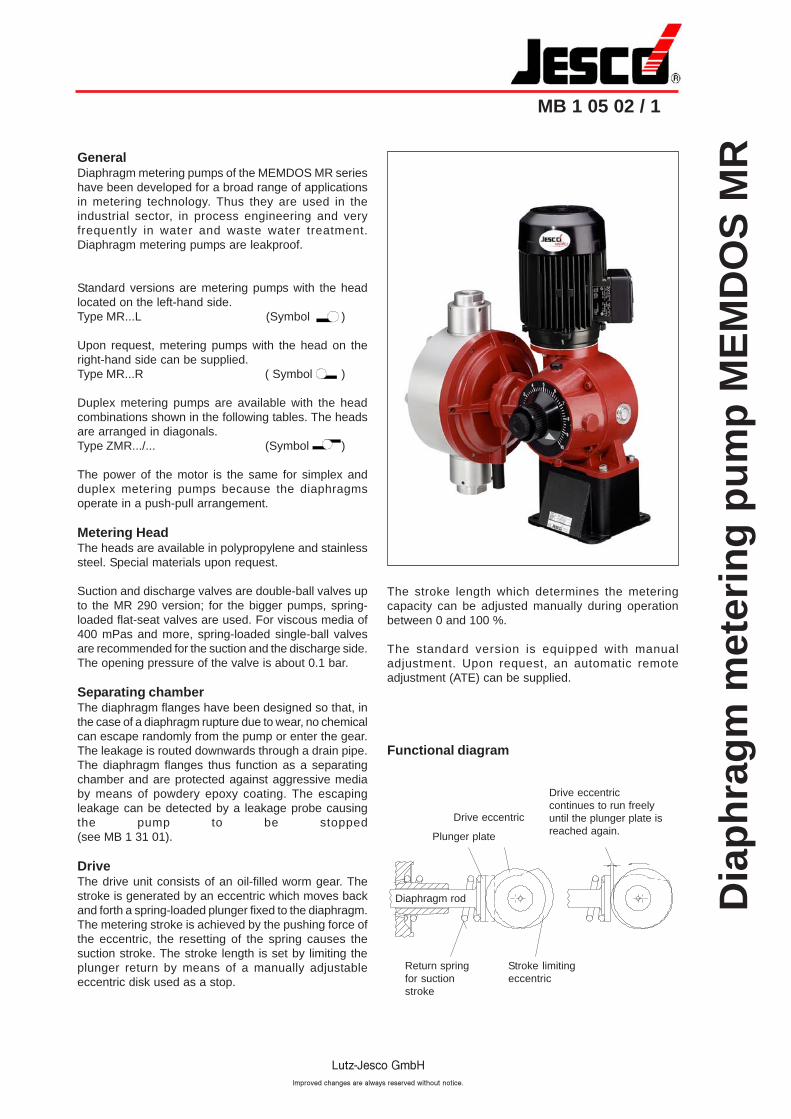
GeneralDiaphragm metering pumps of the MEMDOS MR serieshave been developed for a broad range of applicationsin metering technology. Thus they are used in theindustrial sector, in process engineering and veryfrequently in water and waste water treatment.Diaphragm metering pumps are leakproof.
Standard versions are metering pumps with the headlocated on the left-hand side.Type MR...L (Symbol )
Upon request, metering pumps with the head on theright-hand side can be supplied.Type MR...R ( Symbol )
Duplex metering pumps are available with the headcombinations shown in the following tables. The headsare arranged in diagonals.Type ZMR.../... (Symbol )
The power of the motor is the same for simplex andduplex metering pumps because the diaphragmsoperate in a push-pull arrangement.
Metering HeadThe heads are available in polypropylene and stainlesssteel. Special materials upon request.
Suction and discharge valves are double-ball valves upto the MR 290 version; for the bigger pumps, spring-loaded flat-seat valves are used. For viscous media of400 mPas and more, spring-loaded single-ball valvesare recommended for the suction and the discharge side.The opening pressure of the valve is about 0.1 bar.
Separating chamberThe diaphragm flanges have been designed so that, inthe case of a diaphragm rupture due to wear, no chemicalcan escape randomly from the pump or enter the gear.The leakage is routed downwards through a drain pipe.The diaphragm flanges thus function as a separatingchamber and are protected against aggressive mediaby means of powdery epoxy coating. The escapingleakage can be detected by a leakage probe causingthe pump to be stopped(see MB 1 31 01).
DriveThe drive unit consists of an oil-filled worm gear. Thestroke is generated by an eccentric which moves backand forth a spring-loaded plunger fixed to the diaphragm.The metering stroke is achieved by the pushing force ofthe eccentric, the resetting of the spring causes thesuction stroke. The stroke length is set by limiting theplunger return by means of a manually adjustableeccentric disk used as a stop.
Plunger plate
Drive eccentric
Drive eccentriccontinues to run freelyuntil the plunger plate isreached again.
Stroke limitingeccentric
Return springfor suctionstroke
The stroke length which determines the meteringcapacity can be adjusted manually during operationbetween 0 and 100 %.
The standard version is equipped with manualadjustment. Upon request, an automatic remoteadjustment (ATE) can be supplied.
Functional diagram
Diaphragm rod
Dia
ph
rag
m m
eter
ing
pu
mp
ME
MD
OS
MR
MB 1 05 02 / 2
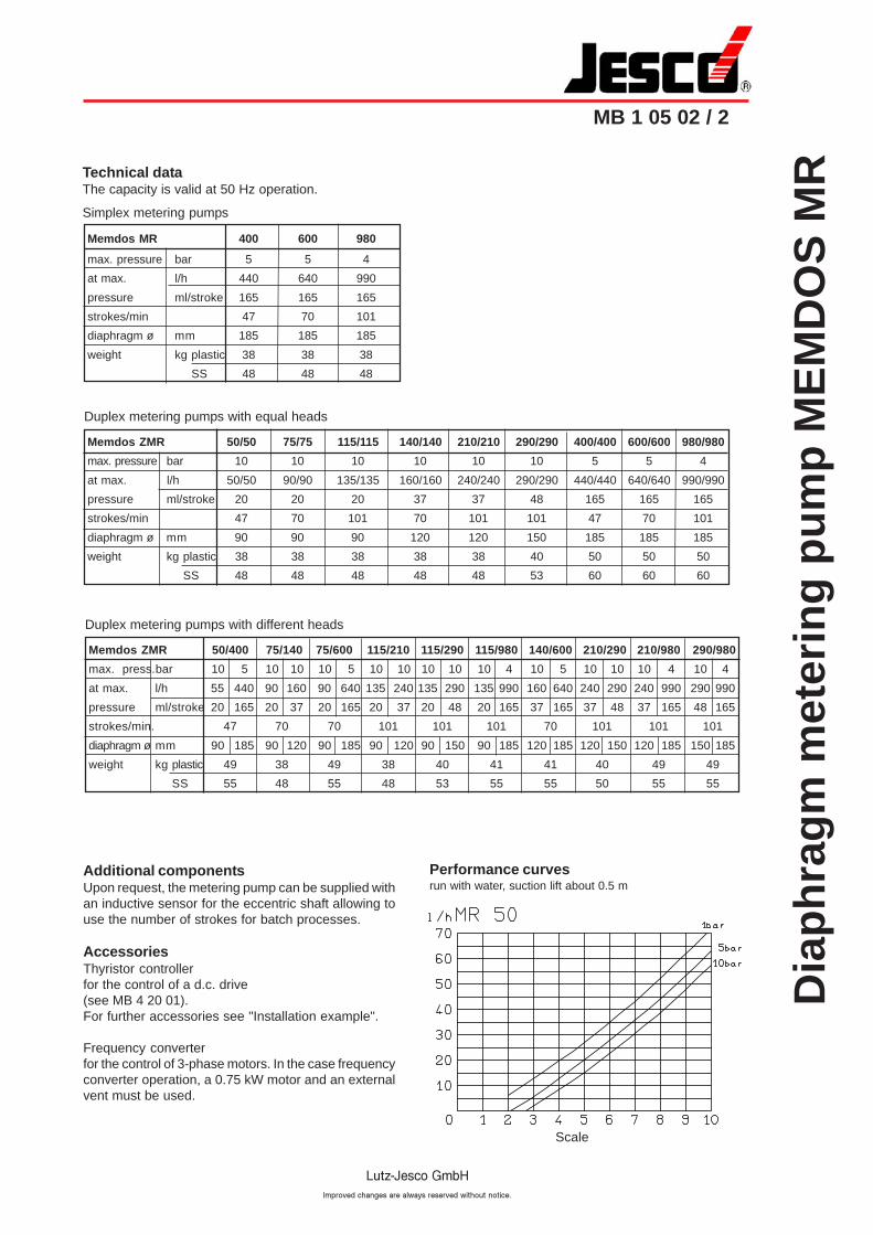
Memdos ZMR 50/400 75/140 75/600 115/210 115/290 115/980 140/600 210/290 210/980 290/980
max. press.bar 10 5 10 10 10 5 10 10 10 10 10 4 10 5 10 10 10 4 10 4
at max. l/h 55 440 90 160 90 640 135 240 135 290 135 990 160 640 240 290 240 990 290 990
pressure ml/stroke 20 165 20 37 20 165 20 37 20 48 20 165 37 165 37 48 37 165 48 165
strokes/min. 47 70 70 101 101 101 70 101 101 101
diaphragm ø mm 90 185 90 120 90 185 90 120 90 150 90 185 120 185 120 150 120 185 150 185
weight kg plastic 49 38 49 38 40 41 41 40 49 49
SS 55 48 55 48 53 55 55 50 55 55
Memdos ZMR 50/50 75/75 115/115 140/140 210/210 290/290 400/400 600/600 980/980
max. pressure bar 10 10 10 10 10 10 5 5 4
at max. l/h 50/50 90/90 135/135 160/160 240/240 290/290 440/440 640/640 990/990
pressure ml/stroke 20 20 20 37 37 48 165 165 165
strokes/min 47 70 101 70 101 101 47 70 101
diaphragm ø mm 90 90 90 120 120 150 185 185 185
weight kg plastic 38 38 38 38 38 40 50 50 50
SS 48 48 48 48 48 53 60 60 60
Memdos MR 400 600 980
max. pressure bar 5 5 4
at max. l/h 440 640 990
pressure ml/stroke 165 165 165
strokes/min 47 70 101
diaphragm ø mm 185 185 185
weight kg plastic 38 38 38
SS 48 48 48
Additional componentsUpon request, the metering pump can be supplied withan inductive sensor for the eccentric shaft allowing touse the number of strokes for batch processes.
AccessoriesThyristor controllerfor the control of a d.c. drive(see MB 4 20 01).For further accessories see "Installation example".
Frequency converterfor the control of 3-phase motors. In the case frequencyconverter operation, a 0.75 kW motor and an externalvent must be used.
Performance curvesrun with water, suction lift about 0.5 m
Simplex metering pumps
Duplex metering pumps with equal heads
Duplex metering pumps with different heads
Technical dataThe capacity is valid at 50 Hz operation.
Scale
Dia
ph
rag
m m
eter
ing
pu
mp
ME
MD
OS
MR
MB 1 05 02 / 3
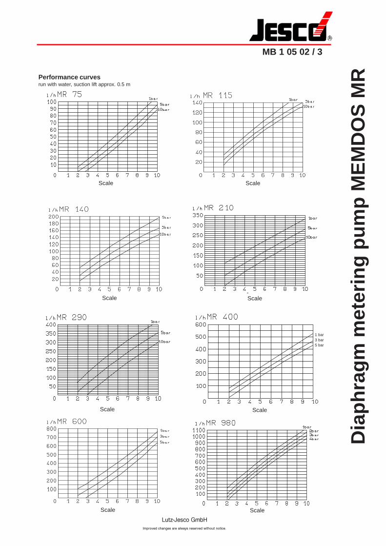
Performance curvesrun with water, suction lift approx. 0.5 m
1 bar3 bar5 bar
Scale Scale
Scale Scale
ScaleScale
Scale Scale
Dia
ph
rag
m m
eter
ing
pu
mp
ME
MD
OS
MR
MB 1 05 02 / 4
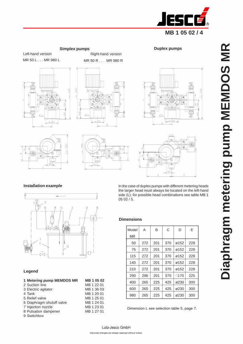
Dimensions
Model A B C D E
MR
50 272 201 370 ø152 228
75 272 201 370 ø152 228
115 272 201 370 ø152 228
140 272 201 370 ø152 228
210 272 201 370 ø152 228
290 296 201 370 170 225
400 265 225 425 ø230 300
600 265 225 425 ø230 300
980 265 225 425 ø230 300
Dimension L see selection table 5, page 7.
Simplex pumps Duplex pumpsLeft-hand version
MR 50 L . . . MR 980 L MR 50 R . . . MR 980 R
In the case of duplex pumps with different metering headsthe larger head must always be located on the left-handside (L); for possible head combinations see table MB 105 02 / 5.
Installation example
Legend
1 Metering pump MEMDOS MR MB 1 05 022 Suction line MB 1 22 013 Electric agitator MB 1 36 034 Tank MB 1 20 015 Relief valve MB 1 25 016 Diaphragm shutoff valve MB 1 24 017 Injection nozzle MB 1 23 018 Pulsation dampener MB 1 27 019 Switchbox
Right-hand version
Dia
ph
rag
m m
eter
ing
pu
mp
ME
MD
OS
MR
MB 1 05 02 / 5
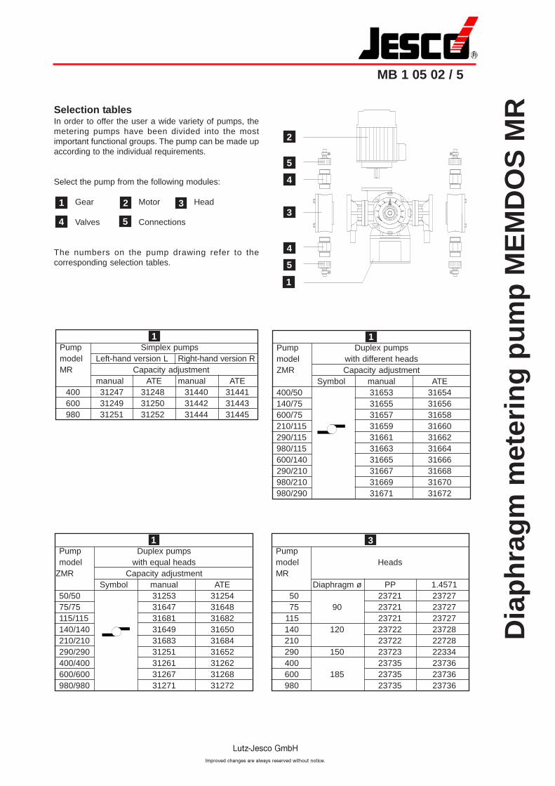
Selection tablesIn order to offer the user a wide variety of pumps, themetering pumps have been divided into the mostimportant functional groups. The pump can be made upaccording to the individual requirements.
Select the pump from the following modules:
Gear Motor Head
Valves Connections
The numbers on the pump drawing refer to thecorresponding selection tables.
1
4 5
2 3
2
5
4
3
1
4
5
Pump Simplex pumpsmodel Left-hand version L Right-hand version RMR Capacity adjustment
manual ATE manual ATE400 31247 31248 31440 31441600 31249 31250 31442 31443980 31251 31252 31444 31445
1
Pump Duplex pumpsmodel with equal heads
ZMR Capacity adjustmentSymbol manual ATE
50/50 31253 3125475/75 31647 31648115/115 31681 31682140/140 31649 31650210/210 31683 31684290/290 31251 31652400/400 31261 31262600/600 31267 31268980/980 31271 31272
1Pumpmodel HeadsMR
Diaphragm ø PP 1.457150 23721 2372775 90 23721 23727
115 23721 23727140 120 23722 23728210 23722 22728290 150 23723 22334400 23735 23736600 185 23735 23736980 23735 23736
3
Pump Duplex pumpsmodel with different headsZMR Capacity adjustment
Symbol manual ATE400/50 31653 31654140/75 31655 31656600/75 31657 31658210/115 31659 31660290/115 31661 31662980/115 31663 31664600/140 31665 31666290/210 31667 31668980/210 31669 31670980/290 31671 31672
1
Dia
ph
rag
m m
eter
ing
pu
mp
ME
MD
OS
MR
MB 1 05 02 / 6
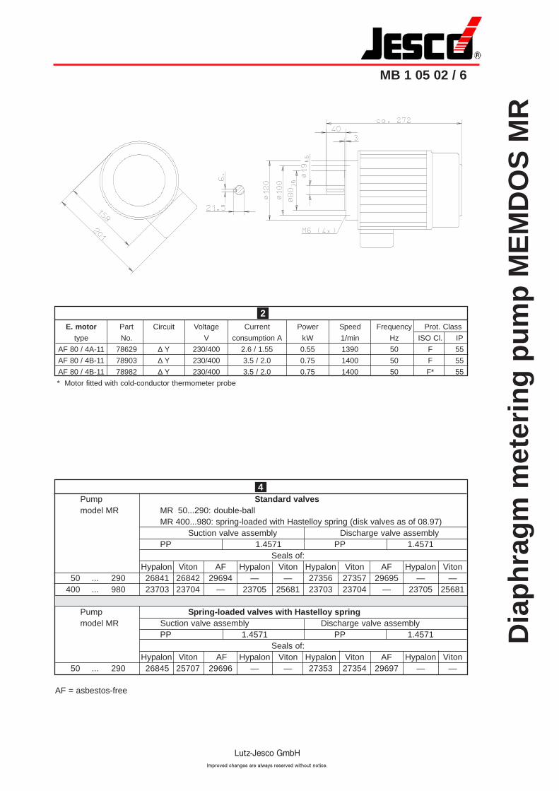
E. motor Part Circuit Voltage Current Power Speed Frequency Prot. Class
type No. V consumption A kW 1/min Hz ISO Cl. IP
AF 80 / 4A-11 78629 ∆ Y 230/400 2.6 / 1.55 0.55 1390 50 F 55
AF 80 / 4B-11 78903 ∆ Y 230/400 3.5 / 2.0 0.75 1400 50 F 55
AF 80 / 4B-11 78982 ∆ Y 230/400 3.5 / 2.0 0.75 1400 50 F* 55
* Motor fitted with cold-conductor thermometer probe
2
Pump Standard valvesmodel MR MR 50...290: double-ball
MR 400...980: spring-loaded with Hastelloy spring (disk valves as of 08.97)Suction valve assembly Discharge valve assembly
PP 1.4571 PP 1.4571Seals of:
Hypalon Viton AF Hypalon Viton Hypalon Viton AF Hypalon Viton50 ... 290 26841 26842 29694 — — 27356 27357 29695 — —
400 ... 980 23703 23704 — 23705 25681 23703 23704 — 23705 25681
Pump Spring-loaded valves with Hastelloy springmodel MR Suction valve assembly Discharge valve assembly
PP 1.4571 PP 1.4571Seals of:
Hypalon Viton AF Hypalon Viton Hypalon Viton AF Hypalon Viton50 ... 290 26845 25707 29696 — — 27353 27354 29697 — —
4
AF = asbestos-free
Dia
ph
rag
m m
eter
ing
pu
mp
ME
MD
OS
MR
MB 1 05 02 / 7
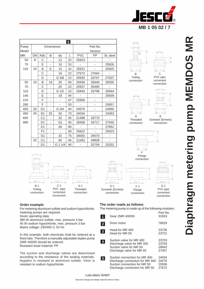
5
DThreaded
connection
BTubing
connection
Order exampleFor metering aluminum sulfate and sodium hypochlorite,metering pumps are required.Given operating data:380 l/h aluminum sulfate, max. pressure 4 bar45 l/h sodium hypochlorite, max. pressure 3 barMains voltage: 230/400 V, 50 Hz
In this example, both chemicals shall be metered at afixed ratio. Therefore a manually adjustable duplex pumpZMR 400/50 should be ordered.Resistant head material: PP
The suction and discharge valves are determinedaccording to the resistance of the sealing materials.Hypalon is resistant to aluminum sulfate. Viton isresistant to sodium hypochlorite.
1
2
EScrewed (Ermeto)
connection
FFlange
connection
B 1Tubing
connection
C 1PVC pipecementedconnection
D 1Threaded
connection
G 1PVC pipecementedconnection
E 1Screwed (Ermeto)
connection
F 1Flange
connection
3
4
5
The order reads as follows:The metering pump is made up of the following modules:
Part No.Gear ZMR 400/50 31653
Drive motor 78629
Head for MR 400 23735Head for MR 50 23721
Suction valve for MR 400 23703Discharge valve for MR 400 23703Suction valve for MR 50 26842Discharge valve for MR 50 27357
Suction connection for MR 400 24034Discharge connection for MR 400 24076Suction connection for MR 50 25936Discharge connection for MR 50 27672
pmuP snoisnemiD .oNtraPledoM noisreV
RM ND .bbA id ad L CVP PP leets.tS05 8 C - 21 22 32952 - -57 E - 01 15 - - 62952511 01 B 9 51 14 12952 - 52952
C - 61 22 27672 46672 -D - 8/3G 22 03952 79733 73072
05 51 B 61 62 05 63952 94653 5395257 C - 02 22 73952 09453 -511 D - 2/1G 22 34952 89733 44952041 E - 81 44 - - 93952012 F - - 74 65952 - -092 F - - 35 - - 75952004 02 1D - 4/3G 04 67042 - 56042004 52 1B 52 43 07 43042 - 36042006 1C - 23 04 88412 07733 -089 1D - 1G 04 85482 71743 04072
1E - 82 08 - - 258721F - - 06 22652 - 326521G - 23 57 05043 07543 -
23 1C - 04 44 19412 82843 -1D - 4/11G 04 - 95723 25252
CPVC pipecementedconnection
Dia
ph
rag
m m
eter
ing
pu
mp
ME
MD
OS
MR
-AT
E
MB 1 05 02 / 9
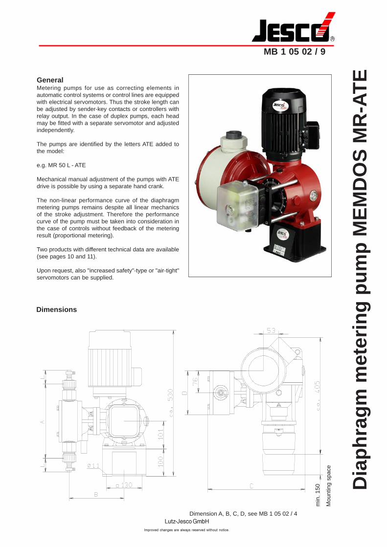
GeneralMetering pumps for use as correcting elements inautomatic control systems or control lines are equippedwith electrical servomotors. Thus the stroke length canbe adjusted by sender-key contacts or controllers withrelay output. In the case of duplex pumps, each headmay be fitted with a separate servomotor and adjustedindependently.
The pumps are identified by the letters ATE added tothe model:
e.g. MR 50 L - ATE
Mechanical manual adjustment of the pumps with ATEdrive is possible by using a separate hand crank.
The non-linear performance curve of the diaphragmmetering pumps remains despite all linear mechanicsof the stroke adjustment. Therefore the performancecurve of the pump must be taken into consideration inthe case of controls without feedback of the meteringresult (proportional metering).
Two products with different technical data are available(see pages 10 and 11).
Upon request, also "increased safety"-type or "air-tight"servomotors can be supplied.
Dimensions
Mou
ntin
g sp
ace
min
. 15
0
Dimension A, B, C, D, see MB 1 05 02 / 4
Dia
ph
rag
m m
eter
ing
pu
mp
ME
MD
OS
MR
-AT
E
MB 1 05 02 / 10
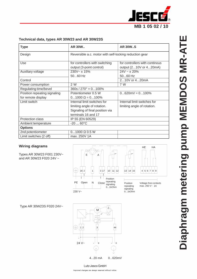
Technical data, types AR 30W23 and AR 30W23S
Type AR 30W.. AR 30W..S
Design Reversible a.c. motor with self-locking reduction gear
Use for controllers with switching for controllers with continousoutput (3-point control) output (2...10V or 4...20mA)
Auxiliary voltage 230V~ ± 15% 24V ~ ± 20%50...60 Hz 50...60 Hz
Control 2...10V or 4...20mAPower consumption 2 W 7 WRegulating time/bevel 360s / 270° = 0...100%Position repeating signaling Potentiometer 0.5 W 0...620mV = 0...100%for remote display 0...1000 Ω= 0...100%Limit switch Internal limit switches for Internal limit switches for
limiting angle of rotation. limiting angle of rotation.Signaling of final position viaterminals 16 and 17
Protection class IP 55 (EN 60529)Ambient temperature -20 ... 60°COptions2nd potentiometer 0...1000 Ω0.5 WLimit switches (2 off) max. 250V 1A
Wiring diagrams
Types AR 30W23 F001 230V~and AR 30W23 F020 24V ~
HAHE
Positionrepeatingsignaling0...1kOhm
16 2 1 3 17 10 11 12 13 14 15 4 5 6 7 8 9
PE N
230 V~
E A
Positionrepeatingsignaling0...1kOhm
Voltage-free contactsmax. 250 V~ 1A
4...20 mA 0...620mV
M
24 V~ - + - +
1 2 3 44
Type AR 30W23S F020 24V~
Open Close
Dia
ph
rag
m m
eter
ing
pu
mp
ME
MD
OS
MR
-AT
E
MB 1 05 02 / 11
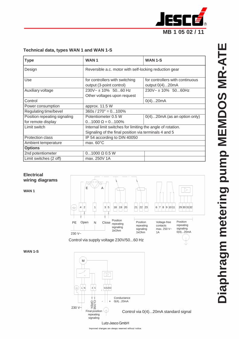
Technical data, types WAN 1 and WAN 1-S
Type WAN 1 WAN 1-S
Design Reversible a.c. motor with self-locking reduction gear
Use for controllers with switching for controllers with continuousoutput (3-point control) output 0(4)...20mA
Auxiliary voltage 230V~ ± 10% 50...60 Hz 230V~ ± 10% 50...60HzOther voltages upon request
Control 0(4)...20mAPower consumption approx. 11.5 WRegulating time/bevel 360s / 270° = 0...100%Position repeating signaling Potentiometer 0.5 W 0(4)...20mA (as an option only)for remote display 0...1000 Ω= 0...100%Limit switch Internal limit switches for limiting the angle of rotation.
Signaling of the final position via terminals 4 and 5Protection class IP 54 according to DIN 40050Ambient temperature max. 60°COptions2nd potentiometer 0...1000 Ω0.5 WLimit switches (2 off) max. 250V 1A
Positionrepeatingsignaling1kOhm
PE N
230 V~
4 2 1 3 5 18 19 20 21 22 23 6 7 8 9 10 11 29 30 3132
E A
Electricalwiring diagrams
WAN 1
230 V~
- +Conductance0(4)...20mA
L N 4 5 515253
M
Control via 0(4)...20mA standard signal
Control via supply voltage 230V/50...60 Hz
WAN 1-S
Positionrepeatingsignaling0(4)...20mA
Voltage-freecontactsmax. 250 V~1A
Positionrepeatingsignaling1kOhm
CLO
SE
Final positionrepeatingsignaling
OP
EN
Open Close