Embed Size (px)
Citation preview
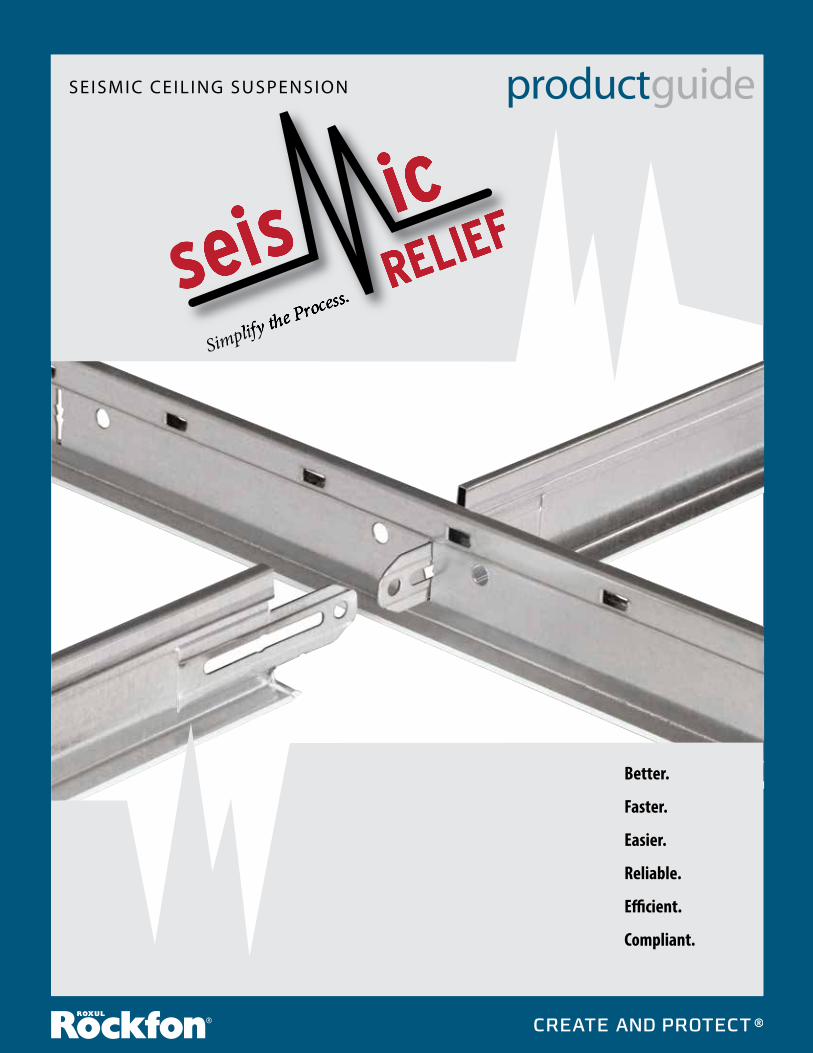
productguide
Better.
Faster.
Easier.
Reliable.
Efficient.
Compliant.
SEISMIC CEIL ING SUSPENSION
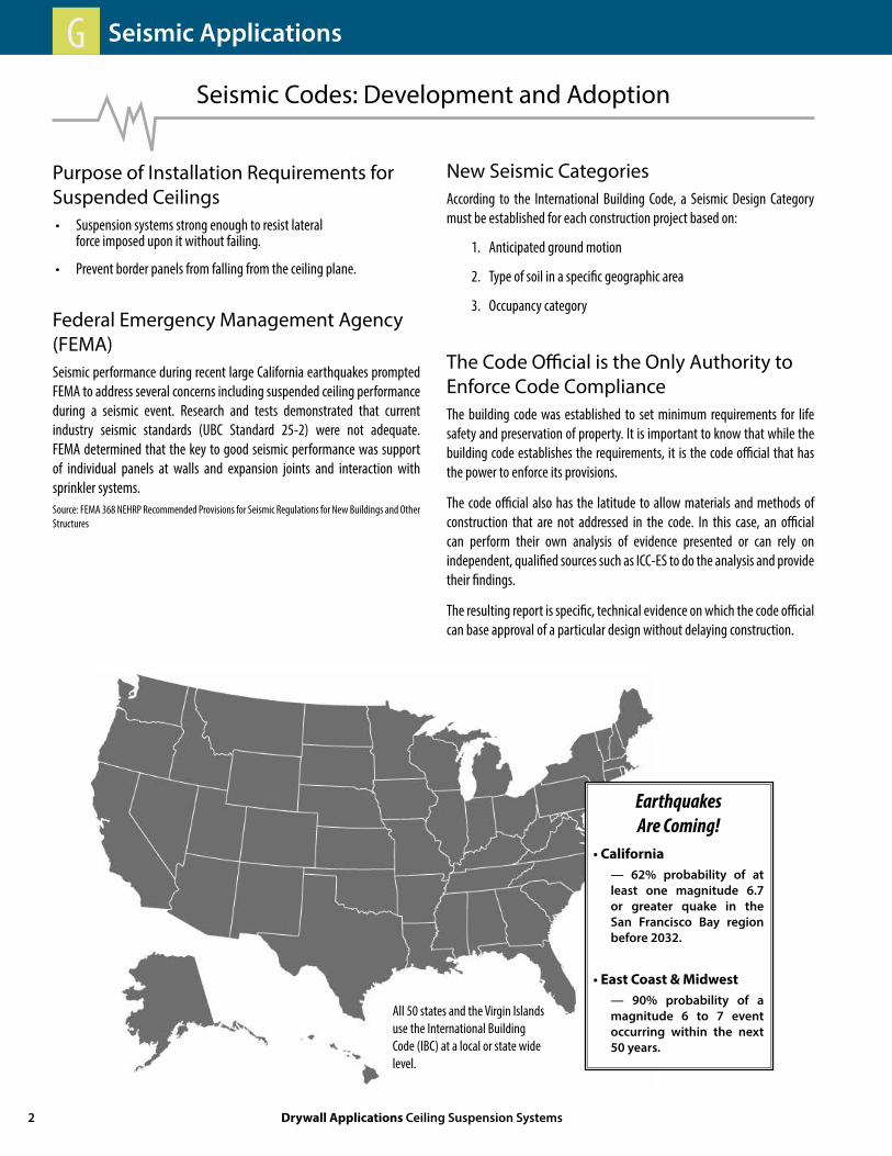
Seismic Codes: Development and Adoption
Purpose of Installation Requirements for Suspended Ceilings• Suspension systems strong enough to resist lateral force imposed upon it without failing.
• Prevent border panels from falling from the ceiling plane.
Federal Emergency Management Agency (FEMA)Seismic performance during recent large California earthquakes prompted FEMA to address several concerns including suspended ceiling performance during a seismic event. Research and tests demonstrated that current industry seismic standards (UBC Standard 25-2) were not adequate. FEMA determined that the key to good seismic performance was support of individual panels at walls and expansion joints and interaction with sprinkler systems.Source: FEMA 368 NEHRP Recommended Provisions for Seismic Regulations for New Buildings and Other Structures
The Code Official is the Only Authority to Enforce Code ComplianceThe building code was established to set minimum requirements for life safety and preservation of property. It is important to know that while the building code establishes the requirements, it is the code official that has the power to enforce its provisions.
The code official also has the latitude to allow materials and methods of construction that are not addressed in the code. In this case, an official can perform their own analysis of evidence presented or can rely on independent, qualified sources such as ICC-ES to do the analysis and provide their findings.
The resulting report is specific, technical evidence on which the code official can base approval of a particular design without delaying construction.
New Seismic CategoriesAccording to the International Building Code, a Seismic Design Category must be established for each construction project based on:
1. Anticipated ground motion
2. Type of soil in a specific geographic area
3. Occupancy category
All 50 states and the Virgin Islands use the International Building Code (IBC) at a local or state wide level.
EarthquakesAre Coming!
• California — 62% probability of at least one magnitude 6.7 or greater quake in the San Francisco Bay region before 2032.
• East Coast & Midwest — 90% probability of a magnitude 6 to 7 event occurring within the next 50 years.
2 Drywall Applications Ceiling Suspension Systems
Seismic ApplicationsG

Industry Standard Construction
ASCE 7-05 Section 13.5.6.2.1 Seismic Design Category CReference CISCA Recommendations for Seismic Zones 0 - 2
• The ceiling must be a free-floating system, not attached at any walls.
• Main and Cross Tees need a minimum of 3/8) clearance from the walls.
• All perimeter grid components must be tied together to prevent spreading using Spacer Bars, or other means.
• Must use Safety Wires on light fixtures.
• Perimeter Support Wires required if Wall Angle support ledge is less than 7/8).
• Intermediate Duty system, 60 lb. minimum connection strength. Use of hook Cross Tee connection is acceptable.
• Refer to IBC 2006, ASCE 7-05 and CISCA Seismic Zones 0 & 2 for complete details.
ASCE 7-05 Section 13.5.6.2.2 Seismic Design Categories D thru FReference CISCA Recommendations for Seismic Zones 3 & 4
• Ceiling areas less than 144 ft2 are exempt of standard construction requirements.
• Heavy Duty suspension system must be used.
• All system connections need to withstand a minimum connection strength of 180 lbs.
• A Wall Angle with a 2) ledge support must be used at the perimeter.
• Ceiling must be attached on two adjacent walls.
• The opposing walls must be unattached, with a 3/4) clearance from the wall for the Main or Cross Tees.
• Spacer Bars, or other means, must be used to tie perimeter components together on unattached walls to prevent spreading.
• Perimeter Wires must be used within 8) from the wall on all four walls.
• Safety Wires must be attached to the light fixtures.
• Light Fixtures must be positively attached to the grid system.
• Ceiling penetrations, like sprinklers, must provide clearance for movement.
• Ceiling areas larger than 1,000 ft2 require horizontal restraint every 144 ft2 consisting of four diagonal Splay Wires or rigid braces in combination with a Compression Post.
• Ceiling areas larger than 2,500 ft2 require a Seismic Separation Joint.
• Ceilings subject to special inspection per ASCE 7-05 Section 13.5.6.2.2 (h).
• Refer to IBC 2006, ASCE 7-05 and CISCA Seismic Zones 3 & 4 for complete details.
800.323.7164 / Fax: 800.222.3744 / rockfon.com 3
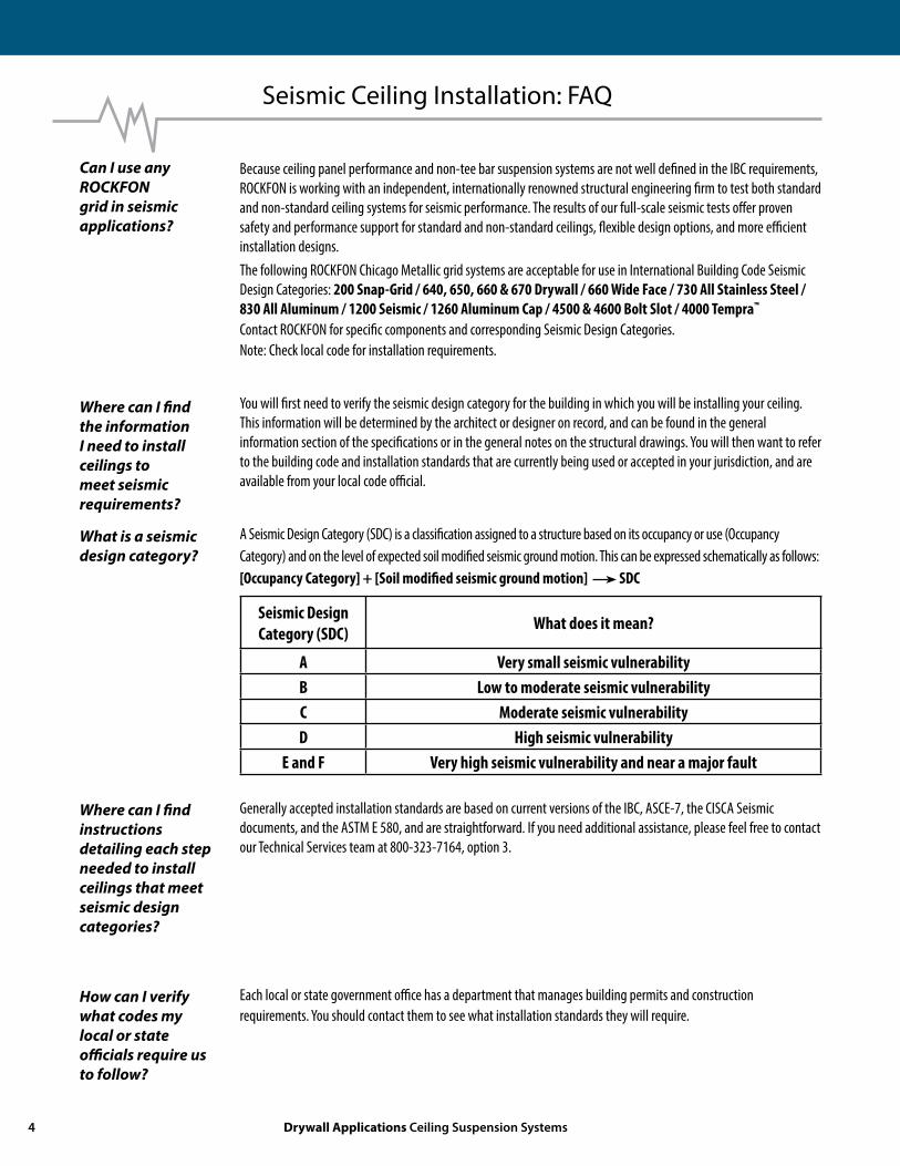
Because ceiling panel performance and non-tee bar suspension systems are not well defined in the IBC requirements, ROCKFON is working with an independent, internationally renowned structural engineering firm to test both standard and non-standard ceiling systems for seismic performance. The results of our full-scale seismic tests offer proven safety and performance support for standard and non-standard ceilings, flexible design options, and more efficient installation designs. The following ROCKFON Chicago Metallic grid systems are acceptable for use in International Building Code Seismic Design Categories: 200 Snap-Grid / 640, 650, 660 & 670 Drywall / 660 Wide Face / 730 All Stainless Steel / 830 All Aluminum / 1200 Seismic / 1260 Aluminum Cap / 4500 & 4600 Bolt Slot / 4000 Tempra™
Contact ROCKFON for specific components and corresponding Seismic Design Categories.Note: Check local code for installation requirements.
You will first need to verify the seismic design category for the building in which you will be installing your ceiling. This information will be determined by the architect or designer on record, and can be found in the general information section of the specifications or in the general notes on the structural drawings. You will then want to refer to the building code and installation standards that are currently being used or accepted in your jurisdiction, and are available from your local code official.
A Seismic Design Category (SDC) is a classification assigned to a structure based on its occupancy or use (Occupancy Category) and on the level of expected soil modified seismic ground motion. This can be expressed schematically as follows:[Occupancy Category] + [Soil modified seismic ground motion] SDC
Seismic DesignCategory (SDC) What does it mean?
A Very small seismic vulnerabilityB Low to moderate seismic vulnerabilityC Moderate seismic vulnerabilityD High seismic vulnerability
E and F Very high seismic vulnerability and near a major fault
Generally accepted installation standards are based on current versions of the IBC, ASCE-7, the CISCA Seismic documents, and the ASTM E 580, and are straightforward. If you need additional assistance, please feel free to contact our Technical Services team at 800-323-7164, option 3.
Each local or state government office has a department that manages building permits and construction requirements. You should contact them to see what installation standards they will require.
Can I use any ROCKFON grid in seismic applications?
Where can I find the information I need to install ceilings to meet seismic requirements?
Where can I find instructions detailing each step needed to install ceilings that meet seismic design categories?
How can I verify what codes my local or state officials require us to follow?
Seismic Ceiling Installation: FAQ
What is a seismic design category?
4 Drywall Applications Ceiling Suspension Systems

ROCKFON has designed a seismic perimeter clip, item #1496.00, which provides for the use of a 15/16) wall angle while eliminating the need for perimeter spacer bars. This clip has been recognized by ICC-ES as an alternative installation that is compliant with the IBC. Official approval of this alternative remains the purview of the Authority Having Jurisdiction (AHJ). See ICC-ES ESR-2282 at www.icc-es.org.
ROCKFON’s Chicago Metallic seismic grid system, including the 1496.00 perimeter clip, was rigorously tested at the Structural Engineering Earthquake Simulation Laboratory (SEESL) at the State University of New York at Buffalo. The evaluation process, including room size testing on shake tables at the University were monitored by engineers from ROCKFON and the State University of New York at Buffalo, as well as by engineers from an independent structural engineering group, to insure accurate data was properly collected and summarized. This report was then submitted to ICC-ES, where our suspended ceiling grid and perimeter clip has been recognized by ICC-ES to perform as required by the current IBC.
Our evaluation report (ICC-ESR 2282) from ICC-ES can be found on their website at www.icc-es.org. The evaluation report can be found under the search function on the website, by entering either our manufacturers’ name (ROCKFON), or our ICC-ES report number (2282). The report will provide in detail the evaluation of our product and proper installation requirements.
ROCKFON has designed what we believe is the only seismic separation joint alternative that has been both tested at the State University of New York at Buffalo and evaluated by an independent, internationally-renowned structural engineering group. The Seismic Separation Tee (SST) from ROCKFON has been designed to provide movement due to seismic activity along the separation joint. Seismic activity causes the SST tees to move linearly, thus eliminating the need for a conventional separation joint.
Other benefits over competitive products or standard recommended installations include: a one-step installation process – Just insert the tees and install push rivets to create the expansion joint, and you are done. There is no going back to cut main or cross tees or to add additional channels, angles or clips.
Our independent structural engineering group has written a summary report that shows that our SST performs in such a way that meets the requirements outlined by the IBC. This report can be delivered directly to the code official by contacting ROCKFON and providing us with the code officials contact information (name, address) along with the project name and location.
My building owner does not like the 2) wall molding that is required in IBC seismic design categories D, E and F. Is there an alternative?
How can local code officials be sure that the use of the Chicago Metallic perimeter clip 1496.00 is compliant with the IBC?
Where can the local code officials or I find verification of the testing, or recognition byICC-ES?
Seismic Ceiling Installation: FAQ
Has an alternative method for seismic separation joints been developed yet?
Is there written documentation for the SST too?
800.323.7164 / Fax: 800.222.3744 / rockfon.com 5
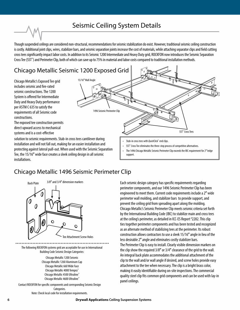
Seismic Ceiling System Details
Chicago Metallic 1496 Seismic Perimeter Clip
Though suspended ceilings are considered non-structural, recommendations for seismic stabilization do exist. However, traditional seismic ceiling construction is costly. Additional joint clips, wires, stabilizer bars, and seismic separation joints increase the cost of materials, while attaching separator clips and field cutting cross tees significantly impact labor costs. In addition to its Seismic 1200 Intermediate and Heavy Duty grid, ROCKFON now introduces the Seismic Separation Cross Tee (SST™) and Perimeter Clip, both of which can save up to 75% in material and labor costs compared to traditional installation methods.
Each seismic design category has specific requirements regarding perimeter components, and our 1496 Seismic Perimeter Clip has been engineered to meet them. Current code requirements include a 2) wide perimeter wall molding, and stabilizer bars to provide support, and prevent the ceiling grid from spreading apart along the molding.Chicago Metallic’s Seismic Perimeter Clip meets seismic criteria set forth by the International Building Code (IBC) to stabilize main and cross tees at the ceiling’s perimeter, as detailed in ICC-ES Report #2282. This clip ties together perimeter components and has been tested and recognized as an alternate method of stabilizing tees at the perimeter. Its robust construction allows contractors to use a sleek 15/16) angle in lieu of the less desirable 2) angle and eliminates costly stabilizer bars. The Perimeter Clip is easy to install. Clearly visible dimension markers on the clip show the required 3/8) or 3/4) clearance of the grid to the wall. An integral back plate accommodates the additional attachment of the clip to the wall and/or wall angle if desired, and screw holes provide easy attachment to the tee when necessary. The clip is a bright brass color, making it easily identifiable during on-site inspections. The commercial quality steel clip fits common grid components and can be used with lay-in panel ceilings.
Chicago Metallic’s Exposed Tee grid includes seismic and fire-rated seismic constructions. The 1200 System is offered for Intermediate Duty and Heavy Duty performance per ASTM C 635 to satisfy the requirements of all Seismic code constructions.The exposed tee construction permits direct upward access to mechanical systems and is a cost-effective solution to seismic requirements. Stab-in cross tees cantilever during installation and will not fall out, making for an easier installation and protecting against lateral pull-out. When used with the Seismic Separation Tee, the 15/16) wide face creates a sleek ceiling design in all seismic installations.
Chicago Metallic Seismic 1200 Exposed Grid
The following ROCKFON systems grid are acceptable for use in International Building Code Seismic Design Categories:
Chicago Metallic 1200 Seismic Chicago Metallic 1260 Aluminum Cap Chicago Metallic 660 Wide Face Chicago Metallic 4000 Tempra™
Chicago Metallic 4500 Ultraline™
Chicago Metallic 4600 Ultraline™
Contact ROCKFON for specific components and corresponding Seismic Design Categories.
Note: Check local code for installation requirements.
3/8) and 3/4) dimension markersBack Plate
Tee Attachment Screw Holes
• Stab-in cross tees with QuickClick™ end clips.
• SST™ Cross Tee eliminates the three-step process of competitive alternatives.
• The 1496 Chicago Metallic Seismic Perimeter Clip exceeds the IBC requirement for 2) ledge support.
1496 Seismic Perimeter Clip
SST™ Cross Tees
15/16) Wall Angle
6 Drywall Applications Ceiling Suspension Systems

> > > > PUSH TOWARDS < < < < < < < < PULL AWAY > > > >
Seismic Ceiling System Details
SST™ (Seismic Separation Tee)
Chicago Metallic’s SST™ Seismic Separation Tee offers a ONE-step process to meeting IBC requirements. Each tee has one staked-on stab-in end tab and an opposing elongated integral end. The elongated ends of two SSTs are installed on both sides of the Main Tee that has been designated as the Seismic Joint, then locked in place with two (2) push rivets. In a seismic event, seismic forces cause the tees to move linearly, thus eliminating the need for a conventional separation joint (see photos below).
In addition to the labor saved by going from the THREE-step process of returning to the assembled grid, cutting off tee clips, and installing two-piece brackets, the ONE-step SST process eliminates the need for more channels, wall angles, and additional hanger wires; does not interfere with struts, wires, or ceiling panels; helps keep the grid system square, and preserves the appearance of the gridwork.
The extended integral tab of the SST allows it to push towards and pull away from the designated seismic joint main tee and maintain a strong connection. The push rivets enable the joint to withstand a pullout force in excess of 180 pounds. The internal friction in the joint also provides a measure of damping.
elongated integral end tab staked-on stab-in end tab
designated seismic joint main tee
push rivets lock each SST in place
To install suspended ceilings that exceed 2,500 sq. ft. in seismic zones, the IBC requires separation joints that allow cross tees to move laterally during a seismic event. Traditionally, contractors create their own seismic solutions by assembling the grid and then revisiting the assembly to cut the grid and build up conventional separation joints with tees, channels, and angles. The grid is then stabilized with additional hanger wires. In addition to increased material costs and time on the job, this multi-step process risks incurring delays while the construction method is inspected and approved.
Competitive alternatives to this method include installing a two-piece bracket at main/cross tee intersections. This solution requires the contractor to install the grid, then return to the grid, cut off the cross tee tabs, and attach the bracket with screws.While the system may meet IBC requirements, it is a THREE-step component and labor intensive process.
The Chicago Metallic SST™ is the only product available in the market today that has been both tested at the State University of Buffalo and reviewed by an independent, internationally renowned structural engineering group to be a viable solution for creating seismic separation joints in IBC seismic design categories D, E and F installations.
Conventional Seismic Separation Joint
800.323.7164 / Fax: 800.222.3744 / rockfon.com 7
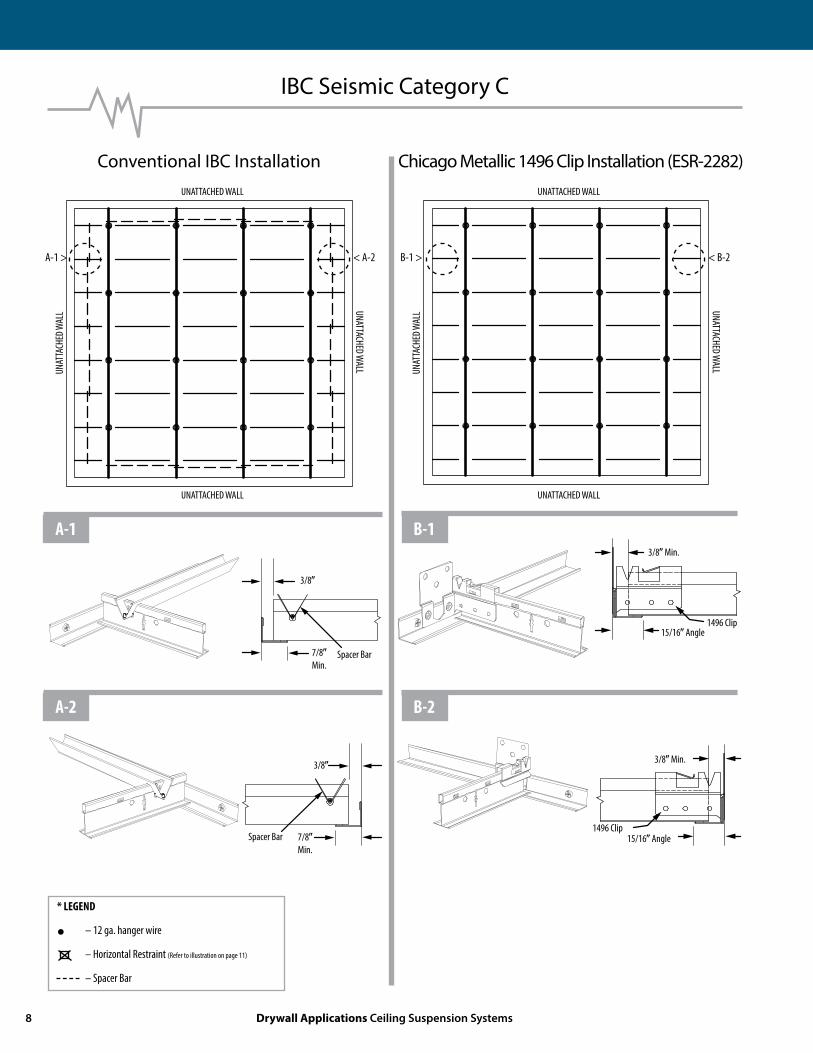
IBC Seismic Category C
A-1 > < A-2 B-1 > < B-2
UNATTACHED WALL
UNAT
TACH
ED W
ALL
UNAT
TACH
ED W
ALL UNATTACHED W
ALL
UNATTACHED WALL
UNATTACHED WALL
UNATTACHED WALL UNATTACHED WALL
Conventional IBC Installation Chicago Metallic 1496 Clip Installation (ESR-2282)
3/8)
3/8)
Spacer Bar7/8)Min.
Spacer Bar 7/8)Min.
3/8) Min.
3/8) Min.
15/16) Angle1496 Clip
1496 Clip15/16) Angle
A-1
A-2
B-1
B-2
* LEGEND
• – 12 ga. hanger wire
– Horizontal Restraint (Refer to illustration on page 11)
– Spacer Bar
8 Drywall Applications Ceiling Suspension Systems
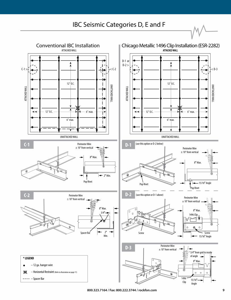
IBC Seismic Categories D, E and F
C-1 > < C-2 < D-3
D-1 or D-2 >
(use this option or D-2 below)
(use this option or D-1 above)
ATTACHED WALL ATTACHED WALL
ATTA
CHED
WAL
L
ATTA
CHED
WAL
L
UNATTACHED WALL
UNATTACHED WALL
ATTACHED WALL
UNATTACHED WALL UNATTACHED WALL
Conventional IBC Installation Chicago Metallic 1496 Clip Installation (ESR-2282)
8) Max.
8) Max.3/4)
Spacer Bar 2)Min.
8) Max.
15/16) Angle
Pop Rivet
15/16) AngleScrew
1496 Clip
15/16)Angle
1496Clip
3/4) from grid to inside of angle
2) Min.
Perimeter Wire± 10° from vertical Perimeter Wire
± 10° from vertical
Perimeter Wire± 10° from vertical
Perimeter Wire± 10° from vertical
Pop Rivet
Screw
C-1
C-2
D-1
D-3
D-2
12( O.C. 6( max.
12( O.C.
6( max.
12( O.C. 6( max.
12( O.C.
6( max.
* LEGEND
• – 12 ga. hanger wire
– Horizontal Restraint (Refer to illustration on page 11)
– Spacer Bar
Pop Rivet
Perimeter Wire± 10° from vertical
8) Max.
8) Max.
800.323.7164 / Fax: 800.222.3744 / rockfon.com 9
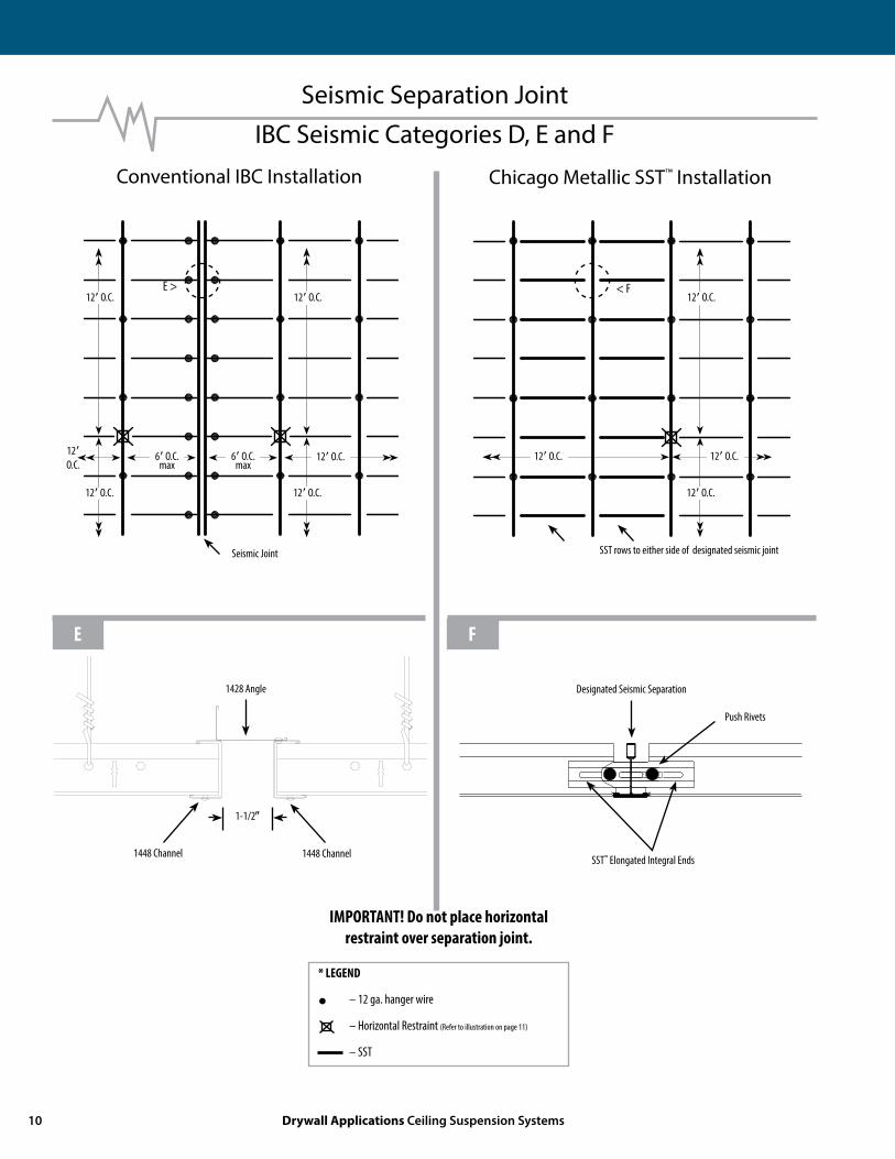
Seismic Separation JointIBC Seismic Categories D, E and F
Conventional IBC Installation Chicago Metallic SST™ Installation
1-1/2)
1448 Channel 1448 Channel
1428 Angle Designated Seismic Separation
SST™ Elongated Integral Ends
Seismic Joint SST rows to either side of designated seismic joint
Push Rivets
12( O.C.
12( O.C.
12( O.C.
12( O.C.
12(O.C.
12( O.C.6( O.C.max
6( O.C.max
* LEGEND
• – 12 ga. hanger wire
– Horizontal Restraint (Refer to illustration on page 11)
– SST
IMPORTANT! Do not place horizontal restraint over separation joint.
E > < F
E F
12( O.C.
12( O.C.
12( O.C. 12( O.C.
10 Drywall Applications Ceiling Suspension Systems

Seismic Horizontal Restraint
These horizontal restraint points shall be placed 12( O.C. in both directions with the first point within 6( of each wall. Brace Wires shall be attached to Main Tees within 2) of Cross Tee intersection, at a maximum angle of 45° relative to ceiling plane. Wires shall be tied with a minimum of three tight wraps (see ASTM C 636 for examples).
For complete details, please refer to the current version of ASCE 7.
Vertical Struts — Allowable LengthsMaximum Recommended Length for Vertical Struts1
EMT Conduit
1/2) EMT ....................................................... up to 5(10)
3/4) EMT ......................................................... up to 7(8)
1) EMT ............................................................ up to 9(9)
Metal Studs
Single 1-5/8) metal stud (20 gauge) .................................. up to 12(0)
Single 2-1/2) metal stud (20 gauge) .................................. up to 13(6)
Back-to-back 1-5/8) metal stud (20 gauge) ....................... up to 15(0)
Back-to-back 2-1/2) metal stud (25 gauge) ....................... up to 15(0)
Note: Plenum areas greater than 15(0) will require engineering calculations.
1Source: Northwest Wall & Ceiling Bureau Rev. 4/07
12 ga. hanger wire typical 4( O.C.
Vertical Post
12 ga. brace wiresconnected to Main Tee
45° max
45° max
45° max
45° max
800.323.7164 / Fax: 800.222.3744 / rockfon.com 11
Metal Perimeter Trim/ Curvilinear / Flat Metal Panel / Embossed Metal Panel / Linear / Open Plenum / Security
ROCKFON Ceiling Products
Grid General Applications / Special Applications / Drywall Applications
G
M
SNL0027E2014
ROCKFON, LLC 4849 SOUTH AUSTIN AVE., CHICAGO, IL 60638 / USA and Canada: 800-323-7164 / Fax: 800-222-3744 / rockfon.com
Date: 06.2014 | Subject to alterations in range and product technology without prior notice. ROCKFON accepts no responsibility for printing errors.