Embed Size (px)
Citation preview
PRODUCT DEVELOPMENT & TESTING REQUIREMENTS FOR ELECTRIC WHEEL HUB MOTORS
Dipl.-Ing. Johannes Käsgen, Dipl.-Ing. Rüdiger Heim Data Analyses and Wheel Related Components
Fraunhofer LBF, Germany
ABSTRACT Referring to the „Federal Government's National Development Plan for Electric Mobility“ it is Germany’s aim to become the lead market for electric mobility and to keep the leadership in science and automobile industries. The goal is to achieve one million electric vehicles on Germany’s roads until 2020. To be competitive on this market new design optimized for electric vehicles need to be developed. One promising technology for the electric power train is the wheel hub motor. As they are integrated in the wheel, gears and drive shafts are obsolete enabling large potential for savings. In this paper the design and safety challenges for wheel hub motor engineers are described. Beside basic design features, the main focus is on loads for motor and chassis dimensioning. In particular the effects of increased unsprung masses are discussed on basis of measurement data collected with the Fraunhofer concept car. It turns out that due to higher unsprung masses some of the wheel and chassis components are subjected to increased stress on a moderate level. Finally rig testing concepts for wheel hub motors are presented to ensure the structural durability and operational reliability under the influence of acting wheel forces.
INTRODUCTION The component assembly of today’s electric cars is still dominated by the long time tested and for internal combustion engine (ICE) optimized component architecture. But with the new components for the electrical drive train and the missing ICE there are several new degrees of freedom released for future car concepts. Auto body design and sub component arrangements of electric cars will be changed within the next years as the ICE is removed and its space becomes available. One of those components that will participate in this change are wheel-hub motors. Current available prototypes already offer a sufficient performance for small and medium-sized vehicles. With their usage the majority of today’s power train components like drive shaft, differential gear, clutch and sometimes even the whole gears are obsolete. The wheels can be individually controlled which makes the implementation of antilock brakes, traction control system, road handling control or even torque vectoring no longer a question of hardware. In the future those features will be implemented by software controlled power electronics. All those characteristics seem to be very alluring, but it will be a big challenge and a long way to go until those motors can be deployed in a full-production run. Conditional upon the mounting position “close to the road” the elements of the motor have to resist the shocks and excitations caused by the (bad) road conditions. This challenge is even more demanding, if the power electronics are integrated into the motor. Also the effects caused by the higher mass of the wheel hub motors compared to the mass of a conventional wheel carrier cannot be neglected. As discussed later in this paper, this additional mass affects the components fatigue strength by increasing the dynamic loads in wheel and suspension.
Beside those operational conditions also the environmental conditions presuppose stronger protection expenses than a motor in a closed engine compartment needs. And last but not least safety issues have to be solved. The absence of the mechanical connection in between the two wheels of an axle demand for a high dependable torque control system. Otherwise the failure of one motor would result in a yaw momentum as likely cause for an accident. In the following paper those requirements for structural durability and system reliability are addressed and discussed. The examination is based on the results of the research Program “Fraunhofer System Research for Electromobility” (FSEM) which was funded by the Federal Ministry for Education and Research (BMBF) under grant number 13N10597. During this project Fraunhofer scientists have developed a wheel hub Motor and integrated it in a concept car.
Fraunhofer e-concept car - Frecc0
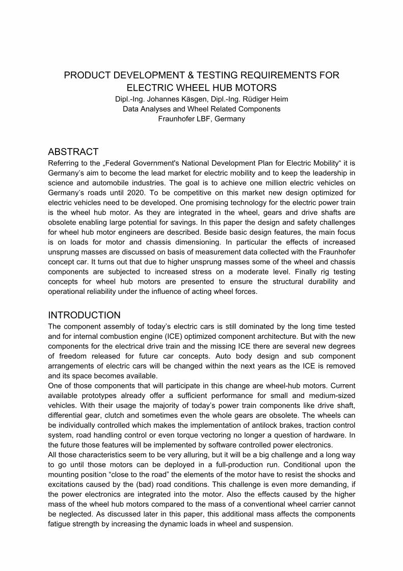
In the FSEM project more than 30 Fraunhofer institutes were involved. The aim was the extensive research on alternative transportation systems and the implementation of the developed technologies in prototypes for hybrid and electric vehicles. One of those prototypes is the Frecc0 (Fraunhofer e-concept car Type0) shown in figure 1 as version 1.0 and 2.0. It is one of the technology demonstrators in which the developed e-mobility components were integrated and tested.
Figure 1: Fraunhofer e-concept car Frecc0; left car: Frecc0 2.0 equipped with two electric
wheel hub motors; right car: Frecc0 1.0 with electric motors near the axle (Foto: Ingo Daute / FhG)
The car body is based on the platform ARTEGA® GT which is a mid-engine sports car manufactured by the Artega® Automobil GmbH & Co. KG in Delbrück, Germany. The Frecc0 is set up in conversion design: the engine was replaced by the e-mobility components while the rest of the body was not modified. In consideration of building up roadworthy demonstrators this is the best manageable solution for electric prototype cars. Beside the two wheel-hub motors on the rear axle there have been other self developed components included in the demonstrator like a battery system with optimized crashworthiness, AC and DC battery chargers, DC-DC converters and controller devices for smart metering. Those components were designed to meet the high requirements of today’s
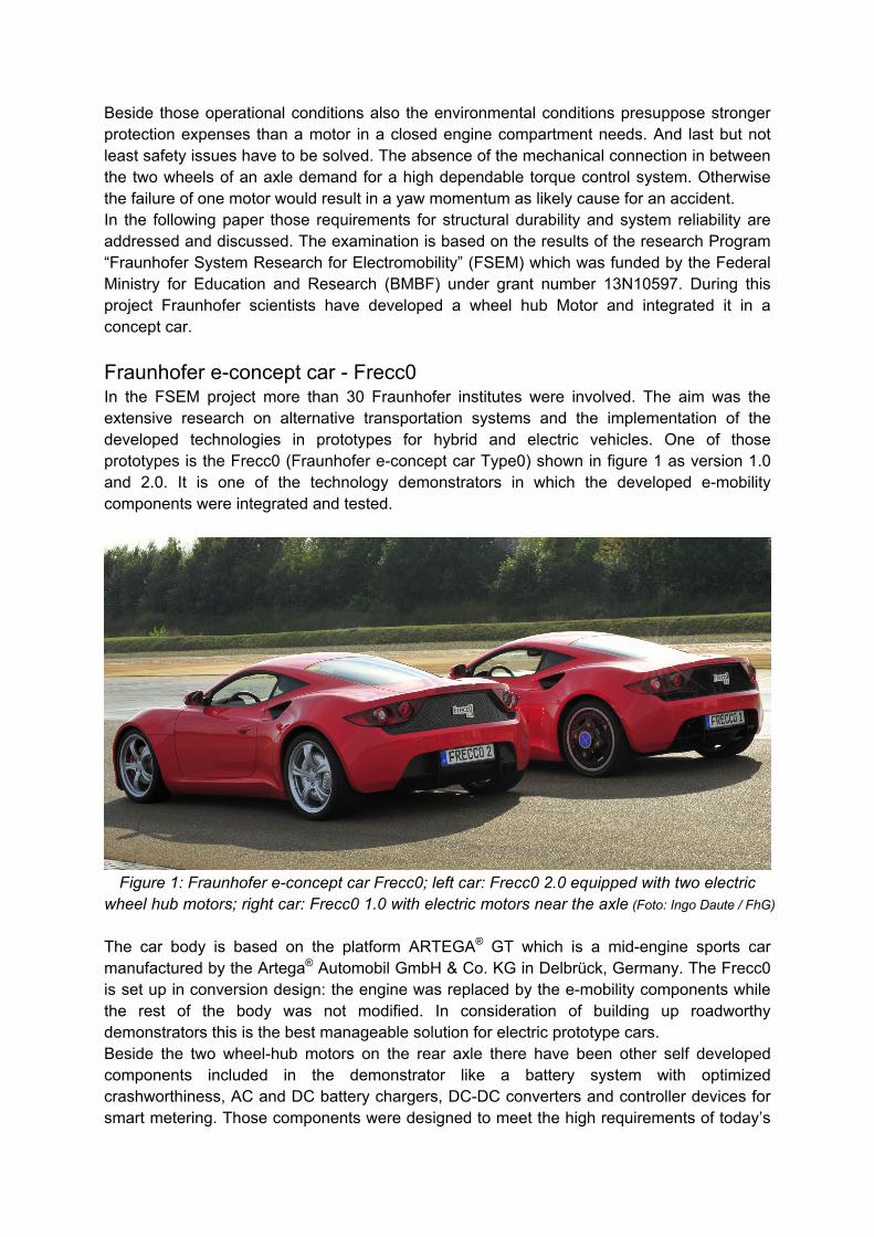
automotive industry which are for example lightweight construction, small design space, maintenance-free operation, high torque and power output and high efficiency. The history of electric motors offers a large variety of functional principles but only a few fulfil those needs. Permanent magnet synchronous motors fit best to those needs and provide sketch to the majority of wheel hub motor concepts. The Fraunhofer wheel-hub motor shown in figure 2 is constructed as such a synchronous motor with permanent-magnet-rotor. Compared to other motors this concept offers a high torque at low weight. The permanent torque rating is designed to 700 Nm with a short time overcharge rating of 900 Nm. The maximum power output of the motor is 55 kW.
Figure 2: Design and wheel carrier integration of the Fraunhofer wheel hub motor
With all sub components the motor has a total weight of 44.2 kg. Figure 2 (right) shows the wheel hub motor mounted at the wheel carrier. The compact dimensions allowed reusing the original mounting points of the triangular control arms. So the kinematic layout of the basic vehicle had not to be changed. With some modifications it was even possible to reuse the original braking system by switching the mounting position of the brake disk to the inside of the wheel carrier.
Design and safety challenges for wheel hub motor engineers A permanent magnet electric motor can be designed as internal as well as external rotor. Generally the rotor contains the magnets while the solenoid coils of the stator are connected to the power electronics. The torque is generated in the air-gap between the magnets and the coils. Linear enlarging of the gap diameter leads to a square increase in torque output, because the perimeter as well as the torsion arm of the rotor is rising. Comparing external and internal rotors with the same overall outer diameter, external rotors have an advantage in generating high torque. The reason is that the magnets with the flux ring are thinner than the coils and therefore a larger gap diameter can be realized. Adverse to the benefit of higher torque is the bearing of external rotors. Designed as bell shape rotor it is necessary to find a rotary shaft seal for the large diameter of the bell. This seal must be a relievable protection for the high voltage components against dust, mud and water in the harsh wheel environment. The seal also needs to withstand radial relative movement as the air-gap slightly deforms under the wheel force. A high stiffness of the bell with its bearing is mandatory to reduce the air-gap deformation and increase the Eigen frequency. If the Eigen frequency is too low, vibration problems may be caused by road or solenoid excitation. When the external rotor is designed as hoop, the sealing is on a smaller diameter and due to lower circumferential speed and no relative movement much better to be
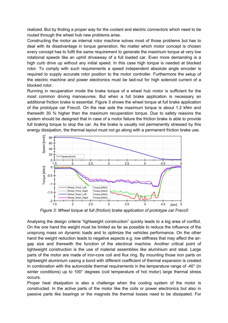
realized. But by finding a proper way for the coolant and electric connectors which need to be routed through the wheel hub new problems arise. Constructing the motor as internal rotor machine solves most of those problems but has to deal with its disadvantage in torque generation. No matter which motor concept is chosen every concept has to fulfil the same requirement to generate the maximum torque at very low rotational speeds like an uphill driveaway of a full loaded car. Even more demanding is a high curb drive up without any initial speed. In this case high torque is needed at blocked rotor. To comply with such requirements a speed independent absolute angle encoder is required to supply accurate rotor position to the motor controller. Furthermore the setup of the electric machine and power electronics must be laid-out for high solenoid current of a blocked rotor. Running in recuperation mode the brake torque of a wheel hub motor is sufficient for the most common driving manoeuvres. But when a full brake application is necessary an additional friction brake is essential. Figure 3 shows the wheel torque at full brake application of the prototype car Frecc0. On the rear axle the maximum torque is about 1.2 kNm and therewith 30 % higher then the maximum recuperation torque. Due to safety reasons the system should be designed that in case of a motor failure the friction brake is able to provide full braking torque to stop the car. As the brake is usually not permanently stressed by this energy dissipation, the thermal layout must not go along with a permanent friction brake use.
1.5 2 2.5 3 3.5 4 4.5 50
20
40
60
80
Spe
ed [k
m/h
]
Speed [km/h]
1.5 2 2.5 3 3.5 4 4.5 5[sec]-2
-1.5
-1
-0.5
0
Tor
que
[kN
m]
Wheel_Front_Left Torque [kNm]
Wheel_Front_Right Torque [kNm]
Wheel_Reart_Left Torque [kNm]
Wheel_Reart_Right Torque [kNm]
Figure 3: Wheel torque at full (friction) brake application of prototype car Frecc0
Analysing the design criteria “lightweight construction” quickly leads to a big area of conflict. On the one hand the weight must be limited as far as possible to reduce the influence of the unsprung mass on dynamic loads and to optimize the vehicles performance. On the other hand the weight reduction leads to negative aspects e.g. low stiffness that may affect the air-gap size and therewith the function of the electrical machine. Another critical point of lightweight construction is the use of material assemblies like aluminium and steal. Large parts of the motor are made of iron-core coil and flux ring. By mounting those iron parts on lightweight aluminium casing a bond with different coefficient of thermal expansion is created. In combination with the automobile thermal requirements in the temperature range of -40° (in winter conditions) up to 100° degrees (coil temperature of hot motor) large thermal stress occurs. Proper heat dissipation is also a challenge when the cooling system of the motor is constructed. In the active parts of the motor like the coils or power electronics but also in passive parts like bearings or the magnets the thermal losses need to be dissipated. For
small motors air cooling can sometimes be realized. But if higher energy amounts have to be dissipated or when power electronics create a punctual heat source liquid cooling is mandatory. Needless to say that the water tightness of the cooling circuit must be absolutely assured to prevent isolation faults of the HV system. After solving all those mechanical requirements, also electronics and software modules have to be designed properly. Since wheel hub motors are mechatronical components the functional safety of the drive concept has to be observed in reference to ISO 26262. A hazard analysis and risk classification of the single wheel drive leads to the conclusion, that asynchronous torque on an axle (if not requested by the torque vectoring control) is a major threat because of the resulting yaw moment. Especially the case of (one) motor failure at full torque and high speed is potentially life-threatening when oncoming traffic is approaching. According to that, monitoring modules for fault detection need to be implemented to minimize the failure probability. This requires an intense and reliable networking of all electronic vehicle components with clearly defined protocols and condition. In case of a severe accident with damaged motor components, the security mechanisms must still be able to shut-off the HV electric system for protection of the rescue team.
Influence of increased tire sprung masses on loads and driving dynamics A wheel-hub motor is a significant additional weight for the wheel carrier. Dependent on the power output and the scale of integration, today’s available motor concepts have a specific weight of roughly 1 kg per kW. In case of the Fraunhofer prototype car Frecc0 the weight of the wheel carrier (incl. wheel, tire, braking system and arms) was increased from 50 kg to 90 kg. This additional mass is not suspended by the vehicles spring damper system. It is coupled only with the stiffness of the tire (tire sprung mass) to the road. When driving on rough road sections, high acceleration amplitudes are generated. The concern is, that with more mass being accelerated the dynamic forces acting on the chassis rise. Also the vehicle dynamic may be influenced negatively. To evaluate the effect of this additional mass, test drives have been performed with a (conventionally powered) Artega. An additional mass of 40 kg, which is about the mass of the Fraunhofer Wheel hub motor, was attached to the wheel carrier. 17 kg have been mounted directly at the carrier and 23 kg on the rotating system (wheel and disk depth adapter). As apparent from table 1, the masses have been added in different steps to distinguish between effects caused by rotary and stationary extra weight.
setup description wheel rotary extraweight stationary extraweight# 1 standard standard - -# 2 wheel forces wheel force transducers 10 kg -# 3 standard + stat.mass standard - 17 kg# 4 wheel forces + stat.mass wheel force transducers 10 kg 17 kg# 5 wf + stat. mass + rot. mass wheel force transducers 23 kg 17 kg
Table 1: Mass configuration of wheel carrier during test drives to evaluate the influence of additional masses on chassis loads and vehicle dynamic.
The test drives have been performed on the test track “ATP” in Papenburg. The route sections can be divided into durability relevant test routes (e.g. concrete plate jolts, pavement, curvy and rough country roads, manhole covers) and manoeuvres to evaluate the vehicle dynamic (e.g. slalom, handling course). During the tests the load and driving condition have been recorded with extensive sensor equipment. The arms of each wheel carrier were strain gage equipped to measure the inner forces of the chassis while the external loads were measured by wheel force transducers. Tri-axial accelerometers picked up the vibrations at
the wheel carrier and the vehicle body. In addition the spring compression was measured with string potentiometers. In combination with GPS Data and information from the vehicle bus a comprehensive knowledge of the vehicles condition was generated. The test setup in combination with the acquired sensor data allows an objective A to B comparison of the vehicle in unmodified configuration and with additional masses on the wheel hub. To eliminate the drivers influence on the test results, all tests have been performed with five different drivers. The driver team consisted of “average drivers”, versed drivers who are familiar with the car and professional test operators. During the measurement data evaluation the acquired data was analyzed to identify the influence of the additional mass. First the data were separated by the driven sections. Those sections where driving conditions didn’t meet the requirements and were therefore not comparable to other test runs (improper speed, unscheduled braking, wrong test lanes) have been excluded from valuation. For the remaining good sections, load spectra have been calculated based on rain flow counting. Afterwards the spectra of the different drivers have been averaged and normalized by section length. Furthermore the spectra of right and left side of the vehicle were averaged to get a further data reduction. By this processing a solid statistical background was generated for evaluation of additional mass influence. To get a single comparable value for the caused fatigue, the damage sum was calculated on the basis of linear damage hypothesis. An artificial S-N curve with constant slope of k=6 (Miner elementary) was used for this evaluation. In order to make the values tangible they were normalized with the damage sum of the original vehicle configuration.
0.01 0.1 1 10 100 1000 cycles / km-12.5
-10
-7.5
-5
-2.5
0
2.5
5
7.5
10
12.5
Acc
ele
ratio
n [
g]
ACC_HA_Rad_x # 1 + 0kgACC_HA_Rad_x # 2 + 10kgACC_HA_Rad_x # 3 + 17kgACC_HA_Rad_x # 4 + 27kgACC_HA_Rad_x # 5 + 40kg
Measure Setup Mass
0.01 0.1 1 10 100 1000
-5
-2.5
0
2.5
5
Acc
ele
ratio
n [
g]
ACC_HA_Rad_y # 1 + 0kgACC_HA_Rad_y # 2 + 10kgACC_HA_Rad_y # 3 + 17kgACC_HA_Rad_y # 4 + 27kgACC_HA_Rad_y # 5 + 40kg
Measure Setup Mass
0.01 0.1 1 10 100 1000-17.5
-15-12.5
-10-7.5
-5-2.5
02.5
57.510
12.515
17.5
Acc
ele
ratio
n [
g]
ACC_HA_Rad_z # 1 + 0kgACC_HA_Rad_z # 2 + 10kgACC_HA_Rad_z # 3 + 17kgACC_HA_Rad_z # 4 + 27kgACC_HA_Rad_z # 5 + 40kg
Measure Setup Mass
0 0.25 0.5 0.75 1
standardized damage sum [1/km]
# 1# 2# 3# 4# 5
0 0.25 0.5 0.75 1
standardized damage sum [1/km]
# 1# 2# 3# 4# 5
0 0.25 0.5 0.75 1
standardized damage sum [1/km]
# 1# 2# 3# 4# 5
0 1 2 3 4 5
standardized damage sum [1/km]
# 1# 2# 3# 4# 5
0 0.5 1 1.5 2 2.5 3
standardized damage sum [1/km]
# 1# 2# 3# 4# 5
0.01 0.1 1 10 100cycles / km
-2.5
0
2.5
5
For
ce [
kN]
Fx_HA_QL_u [kN] # 1 + 0kgFx_HA_QL_u [kN] # 2 + 10kgFx_HA_QL_u [kN] # 3 + 17kgFx_HA_QL_u [kN] # 4 + 27kgFx_HA_QL_u [kN] # 5 + 40kg
Measure Setup Mass
0.01 0.1 1 10 100
-7.5
-5
-2.5
0
2.5
5
7.5
For
ce [
kN]
Fy_HA_QL_u [kN] # 1 + 0kgFy_HA_QL_u [kN] # 2 + 10kgFy_HA_QL_u [kN] # 3 + 17kgFy_HA_QL_u [kN] # 4 + 27kgFy_HA_QL_u [kN] # 5 + 40kg
Measure Setup Mass
0.01 0.1 1 10 100-2.5
0
2.5
5
7.5
10
12.5
For
c e [
kN]
F_HA_FB [kN] # 1 + 0kgF_HA_FB [kN] # 2 + 10kgF_HA_FB [kN] # 3 + 17kgF_HA_FB [kN] # 4 + 27kgF_HA_FB [kN] # 5 + 40kg
Measure Setup Mass
0 0.5 1 1.5 2
standardized damage sum [1/km]
# 1# 2# 3# 4# 5
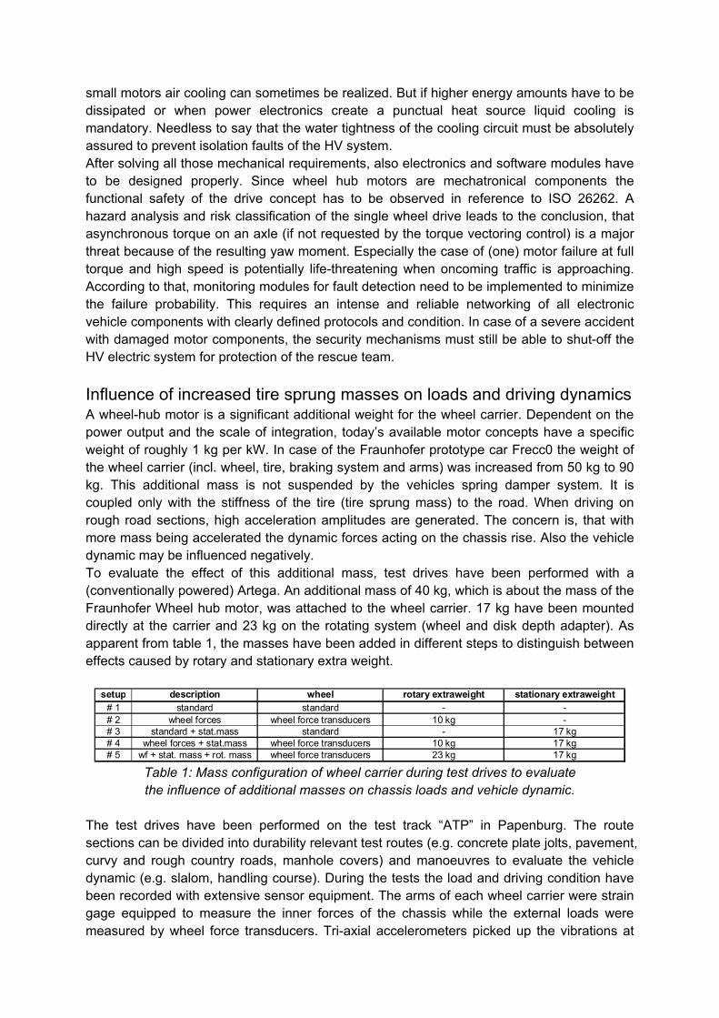
Figure 4: Rear axle acceleration and chassis force spectra that show the influence of
unsprung masses. (left: acceleration spectra of the wheel hub in x,y,z direction; right: force spectra of lower wishbone in x, y direction and strut in z direction)
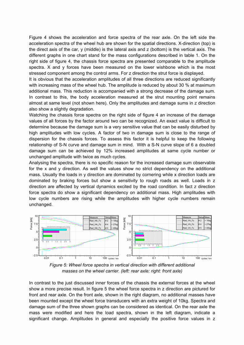
Figure 4 shows the acceleration and force spectra of the rear axle. On the left side the acceleration spectra of the wheel hub are shown for the spatial directions. X-direction (top) is the direct axis of the car, y (middle) is the lateral axis and z (bottom) is the vertical axis. The different graphs in one chart stand for the mass configurations described in table 1. On the right side of figure 4, the chassis force spectra are presented comparable to the amplitude spectra. X and y forces have been measured on the lower wishbone which is the most stressed component among the control arms. For z direction the strut force is displayed. It is obvious that the acceleration amplitudes of all three directions are reduced significantly with increasing mass of the wheel hub. The amplitude is reduced by about 30 % at maximum additional mass. This reduction is accompanied with a strong decrease of the damage sum. In contrast to this, the body acceleration measured at the strut mounting point remains almost at same level (not shown here). Only the amplitudes and damage sums in z direction also show a slightly degradation. Watching the chassis force spectra on the right side of figure 4 an increase of the damage values of all forces by the factor around two can be recognized. An exact value is difficult to determine because the damage sum is a very sensitive value that can be easily disturbed by high amplitudes with low cycles. A factor of two in damage sum is close to the range of dispersion for the chassis forces. To assess this factor it is helpful to keep the following relationship of S-N curve and damage sum in mind. With a S-N curve slope of 6 a doubled damage sum can be achieved by 12% increased amplitudes at same cycle number or unchanged amplitude with twice as much cycles. Analysing the spectra, there is no specific reason for the increased damage sum observable for the x and y direction. As well the values show no strict dependency on the additional mass. Usually the loads in y direction are dominated by cornering while x direction loads are dominated by braking forces but show a sensitivity to rough roads as well. Loads in z direction are affected by vertical dynamics excited by the road condition. In fact z direction force spectra do show a significant dependency on additional mass. High amplitudes with low cycle numbers are rising while the amplitudes with higher cycle numbers remain unchanged.
0.01 0.1 1 10 100 cycles / km
-2.5
0
2.5
5
7.5
10
Fo
rce
[kN
]
Rad_HA_Fz # 2 + 10kg
Rad_HA_Fz # 4 + 27kg
Rad_HA_Fz # 5 + 40kg
Measure Setup Mass
0 0.5 1 1.5 2 2.5 3
standardized damage sum [1/km]
0123456
0.01 0.1 1 10 100 cycles / km
-2.5
0
2.5
5
7.5
10
Fo
rce
[kN
]
Rad_VA_Fz # 2 + 10kg
Rad_VA_Fz # 4 + 27kg
Rad_VA_Fz # 5 + 40kg
Measure Setup Mass
0 0.5 1 1.5 2 2.5 3
standardized damage sum [1/km]
0123456
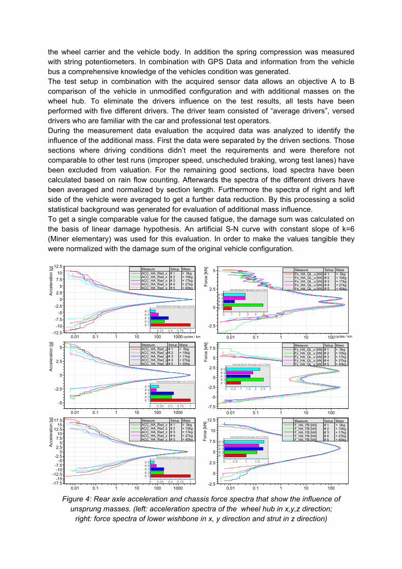
Figure 5: Wheel force spectra in vertical direction with different additional
masses on the wheel carrier. (left: rear axle; right: front axle) In contrast to the just discussed inner forces of the chassis the external forces at the wheel show a more precise result. In figure 5 the wheel force spectra in z direction are pictured for front and rear axle. On the front axle, shown in the right diagram, no additional masses have been mounted except the wheel force transducers with an extra weight of 10kg. Spectra and damage sum of the three shown graphs can be considered as identical. On the rear axle the mass were modified and here the load spectra, shown in the left diagram, indicate a significant change. Amplitudes in general and especially the positive force values in z
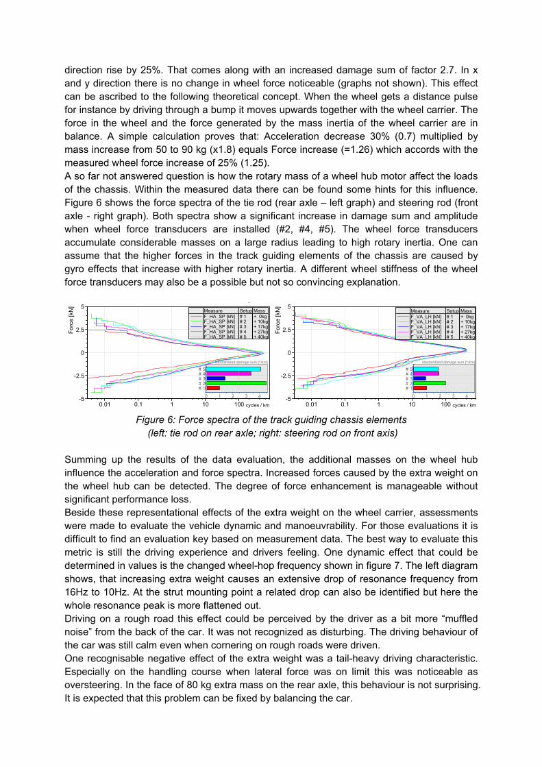
direction rise by 25%. That comes along with an increased damage sum of factor 2.7. In x and y direction there is no change in wheel force noticeable (graphs not shown). This effect can be ascribed to the following theoretical concept. When the wheel gets a distance pulse for instance by driving through a bump it moves upwards together with the wheel carrier. The force in the wheel and the force generated by the mass inertia of the wheel carrier are in balance. A simple calculation proves that: Acceleration decrease 30% (0.7) multiplied by mass increase from 50 to 90 kg (x1.8) equals Force increase (=1.26) which accords with the measured wheel force increase of 25% (1.25). A so far not answered question is how the rotary mass of a wheel hub motor affect the loads of the chassis. Within the measured data there can be found some hints for this influence. Figure 6 shows the force spectra of the tie rod (rear axle – left graph) and steering rod (front axle - right graph). Both spectra show a significant increase in damage sum and amplitude when wheel force transducers are installed (#2, #4, #5). The wheel force transducers accumulate considerable masses on a large radius leading to high rotary inertia. One can assume that the higher forces in the track guiding elements of the chassis are caused by gyro effects that increase with higher rotary inertia. A different wheel stiffness of the wheel force transducers may also be a possible but not so convincing explanation.
0 1 2 3 4
standardized damage sum [1/km]
# 1# 2# 3# 4# 5
y
0.01 0.1 1 10 100 cycles / km-5
-2.5
0
2.5
5
Fo
rce
[kN
]
F_HA_SP [kN] # 1 + 0kgF_HA_SP [kN] # 2 + 10kgF_HA_SP [kN] # 3 + 17kgF_HA_SP [kN] # 4 + 27kgF_HA_SP [kN] # 5 + 40kg
Measure Setup Mass
0 1 2 3 4
standardized damage sum [1/km]
# 1# 2# 3# 4# 5
0.01 0.1 1 10 100 cycles / km-5
-2.5
0
2.5
5
Fo
rce
[kN
]
F_VA_LH [kN] # 1 + 0kgF_VA_LH [kN] # 2 + 10kgF_VA_LH [kN] # 3 + 17kgF_VA_LH [kN] # 4 + 27kgF_VA_LH [kN] # 5 + 40kg
Measure Setup Mass
Figure 6: Force spectra of the track guiding chassis elements
(left: tie rod on rear axle; right: steering rod on front axis) Summing up the results of the data evaluation, the additional masses on the wheel hub influence the acceleration and force spectra. Increased forces caused by the extra weight on the wheel hub can be detected. The degree of force enhancement is manageable without significant performance loss. Beside these representational effects of the extra weight on the wheel carrier, assessments were made to evaluate the vehicle dynamic and manoeuvrability. For those evaluations it is difficult to find an evaluation key based on measurement data. The best way to evaluate this metric is still the driving experience and drivers feeling. One dynamic effect that could be determined in values is the changed wheel-hop frequency shown in figure 7. The left diagram shows, that increasing extra weight causes an extensive drop of resonance frequency from 16Hz to 10Hz. At the strut mounting point a related drop can also be identified but here the whole resonance peak is more flattened out. Driving on a rough road this effect could be perceived by the driver as a bit more “muffled noise” from the back of the car. It was not recognized as disturbing. The driving behaviour of the car was still calm even when cornering on rough roads were driven. One recognisable negative effect of the extra weight was a tail-heavy driving characteristic. Especially on the handling course when lateral force was on limit this was noticeable as oversteering. In the face of 80 kg extra mass on the rear axle, this behaviour is not surprising. It is expected that this problem can be fixed by balancing the car.
0 10 20 30 40 50[Hz]0
0.2
0.4
0.6
0.8
1
1.2
1.4
1.6
1.8
2A
cce
ler a
tion
[g
]
ACC_HA_Rad_z # 1 + 0kgACC_HA_Rad_z # 2 + 10kgACC_HA_Rad_z # 3 + 17kgACC_HA_Rad_z # 4 + 27kgACC_HA_Rad_z # 5 + 40kg
Measure Setup Mass
0 10 20 30 40 50[Hz]0
0.2
0.4
0.6
0.8
1
1.2
1.4
1.6
1.8
2
Acc
ele
r atio
n [g
]
ACC_HA_Dom_z # 1 + 0kgACC_HA_Dom_z # 2 + 10kgACC_HA_Dom_z # 3 + 17kgACC_HA_Dom_z # 4 + 27kgACC_HA_Dom_z # 5 + 40kg
Measure Setup Mass
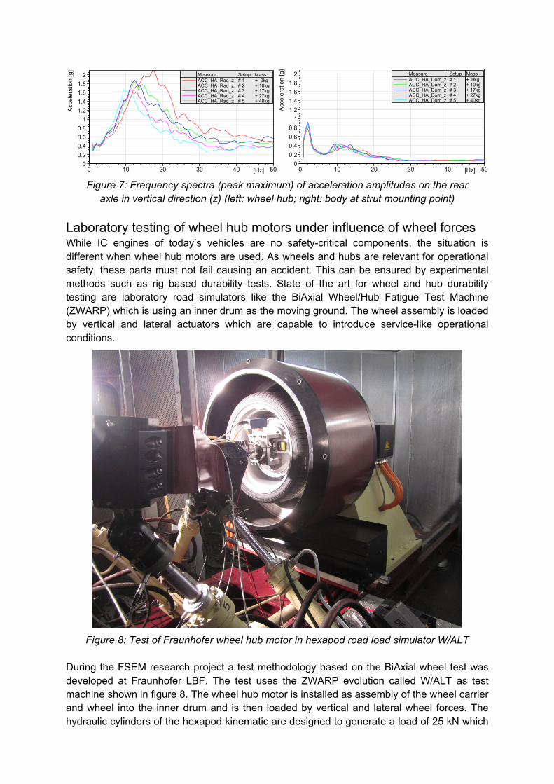
Figure 7: Frequency spectra (peak maximum) of acceleration amplitudes on the rear
axle in vertical direction (z) (left: wheel hub; right: body at strut mounting point)
Laboratory testing of wheel hub motors under influence of wheel forces While IC engines of today’s vehicles are no safety-critical components, the situation is different when wheel hub motors are used. As wheels and hubs are relevant for operational safety, these parts must not fail causing an accident. This can be ensured by experimental methods such as rig based durability tests. State of the art for wheel and hub durability testing are laboratory road simulators like the BiAxial Wheel/Hub Fatigue Test Machine (ZWARP) which is using an inner drum as the moving ground. The wheel assembly is loaded by vertical and lateral actuators which are capable to introduce service-like operational conditions.
Figure 8: Test of Fraunhofer wheel hub motor in hexapod road load simulator W/ALT
During the FSEM research project a test methodology based on the BiAxial wheel test was developed at Fraunhofer LBF. The test uses the ZWARP evolution called W/ALT as test machine shown in figure 8. The wheel hub motor is installed as assembly of the wheel carrier and wheel into the inner drum and is then loaded by vertical and lateral wheel forces. The hydraulic cylinders of the hexapod kinematic are designed to generate a load of 25 kN which
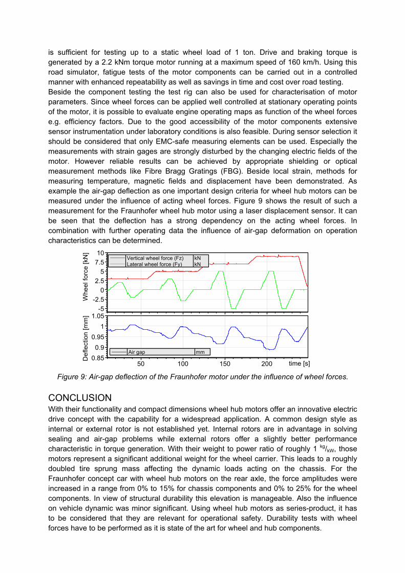
is sufficient for testing up to a static wheel load of 1 ton. Drive and braking torque is generated by a 2.2 kNm torque motor running at a maximum speed of 160 km/h. Using this road simulator, fatigue tests of the motor components can be carried out in a controlled manner with enhanced repeatability as well as savings in time and cost over road testing. Beside the component testing the test rig can also be used for characterisation of motor parameters. Since wheel forces can be applied well controlled at stationary operating points of the motor, it is possible to evaluate engine operating maps as function of the wheel forces e.g. efficiency factors. Due to the good accessibility of the motor components extensive sensor instrumentation under laboratory conditions is also feasible. During sensor selection it should be considered that only EMC-safe measuring elements can be used. Especially the measurements with strain gages are strongly disturbed by the changing electric fields of the motor. However reliable results can be achieved by appropriate shielding or optical measurement methods like Fibre Bragg Gratings (FBG). Beside local strain, methods for measuring temperature, magnetic fields and displacement have been demonstrated. As example the air-gap deflection as one important design criteria for wheel hub motors can be measured under the influence of acting wheel forces. Figure 9 shows the result of such a measurement for the Fraunhofer wheel hub motor using a laser displacement sensor. It can be seen that the deflection has a strong dependency on the acting wheel forces. In combination with further operating data the influence of air-gap deformation on operation characteristics can be determined.
-5
-2.5
0
2.5
5
7.5
10
Whe
el f
orce
[kN
]
Vertical wheel force (Fz) kNLateral wheel force (Fy) kN
50 100 150 200 time [s]0.85
0.9
0.95
1
1.05
De
flect
ion
[mm
]
Air gap mm
Figure 9: Air-gap deflection of the Fraunhofer motor under the influence of wheel forces.
CONCLUSION With their functionality and compact dimensions wheel hub motors offer an innovative electric drive concept with the capability for a widespread application. A common design style as internal or external rotor is not established yet. Internal rotors are in advantage in solving sealing and air-gap problems while external rotors offer a slightly better performance characteristic in torque generation. With their weight to power ratio of roughly 1 kg/kW, those motors represent a significant additional weight for the wheel carrier. This leads to a roughly doubled tire sprung mass affecting the dynamic loads acting on the chassis. For the Fraunhofer concept car with wheel hub motors on the rear axle, the force amplitudes were increased in a range from 0% to 15% for chassis components and 0% to 25% for the wheel components. In view of structural durability this elevation is manageable. Also the influence on vehicle dynamic was minor significant. Using wheel hub motors as series-product, it has to be considered that they are relevant for operational safety. Durability tests with wheel forces have to be performed as it is state of the art for wheel and hub components.