Embed Size (px)
Citation preview

Product Description
SmartRunway® and SmartLanding®
functions of the
Enhanced Ground Proximity Warning System

Product Description – SmartRunway®/SmartLanding®
CAGE CODE: 97896 SCALE: NONE SIZE: A DWG NO. 060-4564-001 REV: D SHEET 2 HIF-1472R6(1)
Table of Contents
1. PURPOSE AND APPLICABILITY ------------------------------------------------------------------------------- 4
2. SYSTEM OVERVIEW ---------------------------------------------------------------------------------------------- 4
2.1 Runway Awareness and Advisory System (RAAS) ------------------------------------------------------------------------------------------ 6
2.2 Stabilized Approach Monitor --------------------------------------------------------------------------------------------------------------------- 7
2.3 Altimeter Monitor ----------------------------------------------------------------------------------------------------------------------------------- 8
2.4 Takeoff Flap Configuration Monitor ------------------------------------------------------------------------------------------------------------ 9
2.5 Long Landing Monitor ------------------------------------------------------------------------------------------------------------------------------ 9
3. GENERAL CHARACTERISTICS ------------------------------------------------------------------------------- 10
3.1 Aural Annunciations ------------------------------------------------------------------------------------------------------------------------------ 10
3.2 Visual Annunciations ----------------------------------------------------------------------------------------------------------------------------- 11
3.3 Options ----------------------------------------------------------------------------------------------------------------------------------------------- 12
4. RUNWAY AWARENESS AND ADVISORY SYSTEM (RAAS) -------------------------------------------- 12
4.1 RAAS Availability and Options ----------------------------------------------------------------------------------------------------------------- 12
4.2 RAAS Routine Advisories ------------------------------------------------------------------------------------------------------------------------ 16
4.3 RAAS Non-Routine Advisories ------------------------------------------------------------------------------------------------------------------ 23
4.4 RAAS Assumptions, Limitations and Constraints ----------------------------------------------------------------------------------------- 35
5. STABILIZED APPROACH MONITOR ------------------------------------------------------------------------ 37
5.1 Stabilized Approach Monitor Availability and Options --------------------------------------------------------------------------------- 37
5.2 Stabilized Approach Monitor Sub-Monitors ----------------------------------------------------------------------------------------------- 40
5.3 Assumptions, Limitations and Constraints ------------------------------------------------------------------------------------------------- 49
6. ALTIMETER MONITOR ---------------------------------------------------------------------------------------- 50
6.1 Altimeter Monitor Availability and Options ------------------------------------------------------------------------------------------------ 50
6.2 Altimeter Monitor Sub-Monitors -------------------------------------------------------------------------------------------------------------- 52
6.3 Assumptions, Limitations, and Constraints ------------------------------------------------------------------------------------------------- 55
7. TAKEOFF FLAP CONFIGURATION MONITOR ------------------------------------------------------------ 55
Product Description – SmartRunway®/SmartLanding®
CAGE CODE: 97896 SCALE: NONE SIZE: A DWG NO. 060-4564-001 REV: D SHEET 3 HIF-1472R6(1)
7.1 Takeoff Flap Configuration Monitor Availability and Options ------------------------------------------------------------------------ 56
7.2 On Runway – Takeoff Flap Configuration Monitor --------------------------------------------------------------------------------------- 57
7.3 Assumptions, Limitations and Constraints ------------------------------------------------------------------------------------------------- 59
8. LONG LANDING MONITOR ----------------------------------------------------------------------------------- 60
8.1 Long Landing Monitor Availability and Options ------------------------------------------------------------------------------------------- 60
8.2 Long Landing Monitor ---------------------------------------------------------------------------------------------------------------------------- 61
8.3 Assumptions, Limitations and Constraints ------------------------------------------------------------------------------------------------- 64
9. CONFIGURATION, ENABLE KEY, AND PROGRAM PIN ------------------------------------------------- 65
9.1 Enable Key ------------------------------------------------------------------------------------------------------------------------------------------- 66
9.2 Reloadable Customer Definitions (RCD) ----------------------------------------------------------------------------------------------------- 66
9.3 Incorporation of the Pilot’s Point of View -------------------------------------------------------------------------------------------------- 67
9.4 RCD Program Pin ----------------------------------------------------------------------------------------------------------------------------------- 72
9.5 Visual Message Options ------------------------------------------------------------------------------------------------------------------------- 72
APPENDICES ----------------------------------------------------------------------------------------------------------- 73
Appendix A: Definitions ----------------------------------------------------------------------------------------------------------------------------------- 73
Appendix B: Runway Awareness and Advisory System Visuals, Aurals and Volume Levels -------------------------------------------- 74
Appendix C: Stabilized Approach Monitor Visuals, Aurals and Volume Levels ------------------------------------------------------------- 79
Appendix D: Altimeter Monitor Visuals, Aurals and Volume Levels --------------------------------------------------------------------------- 80
Appendix E: Takeoff Flap Configuration Monitor Visuals, Aurals and Volume Levels ---------------------------------------------------- 82
Appendix F: Long Landing Monitor Visuals, Aurals and Volume Levels ---------------------------------------------------------------------- 83
Appendix G: Aircraft Compatibility Tables ------------------------------------------------------------------------------------------------------------ 84
Appendix H: Boeing OEM RAAS installation ---------------------------------------------------------------------------------------------------------- 92

Product Description – SmartRunway®/SmartLanding®
CAGE CODE: 97896 SCALE: NONE SIZE: A DWG NO. 060-4564-001 REV: D SHEET 4 HIF-1472R6(1)
1. Purpose and Applicability
The purpose of this document is to describe the functions and features of the Honeywell SmartRunway®
and
SmartLanding®
flight safety functions included in the Enhanced Ground Proximity Warning System (EGPWS), all
of which are non-TSO functions.
The SmartRunway®
function includes the following:
The Runway Awareness & Advisory System (RAAS), including Taxiway Landing and optional caution level
alerts for Taxiway Takeoff and Short Runway on takeoff and landing. These provide alerts and advisories to
increase crew situational awareness during operations on and around airports. It also includes the Incorrect
Takeoff Flap Configuration Monitor.
The SmartLanding®
function includes the following:
The airborne and landing rollout calls of the Runway Awareness & Advisory System (RAAS), the Stabilized
Approach Monitor, the Long Landing Monitor, and the Altimeter Monitor.
This Product Description does not address the TSO functions included in the EGPWS, nor does it address some of
the older developed non-TSO functions. Refer to the Product Specification for the Enhanced Ground Proximity
Warning System (EGPWS) for specifics on EGPWS design, performance, environmental and software design
requirements, and all other functions and features included in the EGPWS: Honeywell Document 965-0976-603,
Revision V or later for the MKV and MKVII EGPWS platforms and Honeywell Document PDS69000940-000 for
the next generation MVK-A platform.
The functions, as described herein, are only applicable to the following EGPWS part numbers:
965-0976-0xx-230-230 or later (MKV)
965-1076-0xx-230-230 or later (MKVII)
965-1690-054 or later (MKV)
965-1676-004 or later (MKV)
69000940 (MKV-A)
69000941 (MKV-A)
69000942 (MKV-A)
In addition to the part number applicability, Terrain Database 454 (or later) is required. Note that a S/W
mod may be required in order to use databases 456 and later – refer to section 4.1.1 for more information.
For prior part numbers only the functionality described in Honeywell document 060-4404-000 is available.
2. System Overview
System overviews of the non-TSO functions of Runway Awareness and Advisories, Stabilized Approach Monitor,
Altimeter Monitor, Takeoff Flap Configuration Monitor, and Long Landing Monitor are described in this section.
These functions offer significant safety enhancements for aircraft equipped with Honeywell‟s MKV, MKVII, or
MKV-A Enhanced Ground Proximity Warning System (EGPWS). They are software enhancements hosted in the
EGPWC.
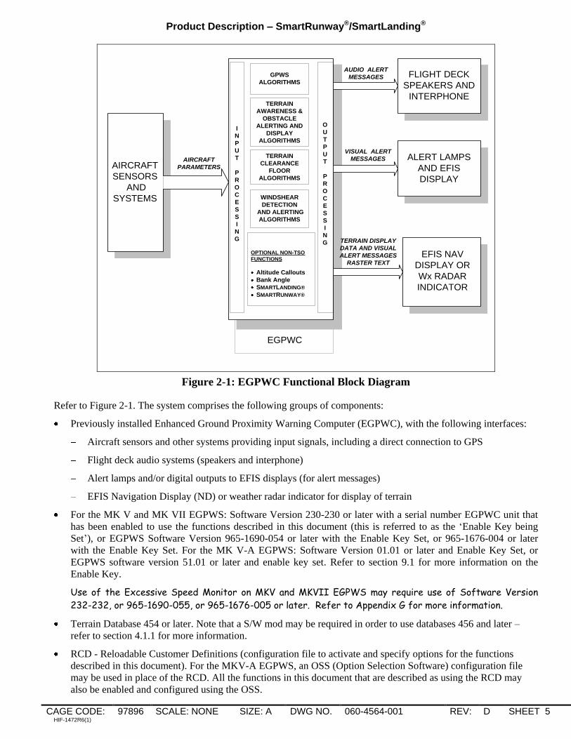
Figure 2-1 provides a functional block diagram of all functions within the EGPWC.
Product Description – SmartRunway®/SmartLanding®
CAGE CODE: 97896 SCALE: NONE SIZE: A DWG NO. 060-4564-001 REV: D SHEET 5 HIF-1472R6(1)
EGPWC
AUDIO ALERT
MESSAGES
AIRCRAFT
PARAMETERS
VISUAL ALERT
MESSAGES
TERRAIN DISPLAY
DATA AND VISUAL
ALERT MESSAGES
RASTER TEXT
GPWS
ALGORITHMS
TERRAIN
AWARENESS &
OBSTACLE
ALERTING AND
DISPLAY
ALGORITHMS
TERRAIN
CLEARANCE
FLOOR
ALGORITHMS
WINDSHEAR
DETECTION
AND ALERTING
ALGORITHMS
ALERT LAMPS
AND EFIS
DISPLAY
FLIGHT DECK
SPEAKERS AND
INTERPHONE
EFIS NAV
DISPLAY OR
Wx RADAR
INDICATOR
AIRCRAFT
SENSORS
AND
SYSTEMS
I
N
P
U
T
P
R
O
C
E
S
S
I
N
G
O
U
T
P
U
T
P
R
O
C
E
S
S
I
N
G
OPTIONAL NON-TSO
FUNCTIONS
Altitude Callouts
Bank Angle
SMARTLANDING®
SMARTRUNWAY®
Figure 2-1: EGPWC Functional Block Diagram
Refer to Figure 2-1. The system comprises the following groups of components:
Previously installed Enhanced Ground Proximity Warning Computer (EGPWC), with the following interfaces:
Aircraft sensors and other systems providing input signals, including a direct connection to GPS
Flight deck audio systems (speakers and interphone)
Alert lamps and/or digital outputs to EFIS displays (for alert messages)
EFIS Navigation Display (ND) or weather radar indicator for display of terrain
For the MK V and MK VII EGPWS: Software Version 230-230 or later with a serial number EGPWC unit that
has been enabled to use the functions described in this document (this is referred to as the „Enable Key being
Set‟), or EGPWS Software Version 965-1690-054 or later with the Enable Key Set, or 965-1676-004 or later
with the Enable Key Set. For the MK V-A EGPWS: Software Version 01.01 or later and Enable Key Set, or
EGPWS software version 51.01 or later and enable key set. Refer to section 9.1 for more information on the
Enable Key.
Use of the Excessive Speed Monitor on MKV and MKVII EGPWS may require use of Software Version
232-232, or 965-1690-055, or 965-1676-005 or later. Refer to Appendix G for more information.
Terrain Database 454 or later. Note that a S/W mod may be required in order to use databases 456 and later –
refer to section 4.1.1 for more information.
RCD - Reloadable Customer Definitions (configuration file to activate and specify options for the functions
described in this document). For the MKV-A EGPWS, an OSS (Option Selection Software) configuration file
may be used in place of the RCD. All the functions in this document that are described as using the RCD may
also be enabled and configured using the OSS.

Product Description – SmartRunway®/SmartLanding®
CAGE CODE: 97896 SCALE: NONE SIZE: A DWG NO. 060-4564-001 REV: D SHEET 6 HIF-1472R6(1)
2.1 Runway Awareness and Advisory System (RAAS)
The Runway Awareness and Advisory System (RAAS) offers improved situational awareness for the flight crew in
order to help lower the probability of runway incursion incidents and accidents by providing timely aural messages to
the flight crew during ground taxi, takeoff (including rejected takeoffs), final approach, and landing/roll-out
operations. Existing EGPWS protection and operation is unaltered by the addition of RAAS.
Advisories/cautions are generated based upon the current aircraft position when compared to the location of the
airport runways, which are stored within the Honeywell EGPWS Runway Database.
The aurals can be grouped into two categories:
Routine Advisories (annunciations the flight crew will hear during routine operations) and
Non-Routine Advisories/Cautions (annunciations the flight crew will seldom or perhaps never hear).
RAAS provides the flight crew with five „routine‟ advisories. Three of these annunciations will be heard by the crew
in normal operations, providing increased position awareness relative to the runway during taxi and flight operations.
They are intended to reduce the risk of a runway incursion. The two remaining „routine‟ advisories provide
information about the aircraft location along the runway, and are intended to reduce the risk of overruns. These
advisories are:
Approaching Runway - In Air advisory provides the crew with awareness of which runway the aircraft is lined-
up with on approach.
Approaching Runway - On-Ground advisory provides the flight crew with awareness of a proximate runway
edge being approached by the aircraft during taxi operations.
On Runway advisory provides the crew with awareness of which runway the aircraft is lined-up with.
Distance Remaining advisories enhance crew awareness of aircraft along-track position relative to the runway
end.
Runway End advisory is intended to improve flight crew awareness of the position of the aircraft relative to the
runway end during low visibility conditions.
In addition, RAAS provides the flight crew with several „non-routine‟ advisories/cautions. These annunciations are
designed to enhance safety and situational awareness in specific situations not routinely encountered during normal
aircraft operations. Some of the RAAS advisories include distance information. The unit of measure used for
distance can be configured to be either meters or feet.
Approaching Short Runway - In-Air advisory provides the crew with awareness of which runway the aircraft is
lined-up with, and that the runway length available may be marginal for normal landing operations. If desired,
an additional caution annunciation can be enabled which provides the crew with awareness that the issue has not
been resolved when the aircraft is on final approach.
Insufficient Runway Length - On-Ground Advisory provides the crew with awareness of which runway the
aircraft is lined-up with, and that the runway length available for takeoff is less than the defined minimum
takeoff runway length. If desired, an additional caution annunciation can be enabled which provides the crew
with awareness that the issue has not been resolved when the aircraft is on the final stage of takeoff.
Extended Holding on Runway advisory provides crew awareness of an extended holding period on the runway.
Taxiway Take-Off advisory enhances crew awareness of excessive taxi speeds or an inadvertent take-off on a
taxiway. If desired, this function can provide a caution annunciation in lieu of an advisory annunciation.
Distance Remaining advisories provides the flight crew with position awareness during a Rejected Take-Off
(RTO).
Taxiway Landing alert provides the crew with awareness that the aircraft is not lined up with a runway at low
altitudes.

Product Description – SmartRunway®/SmartLanding®
CAGE CODE: 97896 SCALE: NONE SIZE: A DWG NO. 060-4564-001 REV: D SHEET 7 HIF-1472R6(1)
Each RAAS function is independently enabled using the RCD. When enabled, the RAAS functions operate
automatically, without any action required from the flight crew.
In addition to the aural annunciations provided, visual annunciations can be activated in the form of caution
indications if the annunciations are considered cautions. Visual text annunciations can also be configured to be
overlaid on the terrain display for a period of time when the condition is entered. System inoperative messages may
be indicated as required using existing GPWS inoperative indications or dedicated RAAS INOP indications (MKV-A
EGPWS or MKV/MKVII -236-236, -057, -006 software versions and later) if supported by aircraft. RAAS
inoperative status will be indicated during the EGPWS Self Test if RAAS is enabled via the RCD and the status
indicates the function is inoperative. RAAS status can be optionally displayed on the Terrain Display. This is active
only when the aircraft is on the ground. Depending on the status, the message may be shown immediately, or it may
require a change in the displayed range (to a higher or lower range) in order to be viewable. Inhibition of the RAAS
function via an external cockpit selection may be configured.
2.2 Stabilized Approach Monitor
Important note: To use the Stabilized Approach Monitor’s Excessive Speed Alert, the EGPWS must have a
source of Approach or Reference Speed. For some aircraft, this means adding additional wiring to connect to
an ARINC 429 source for this data. Refer to Appendix G for a list of EGPWS aircraft types that can select
the Excessive Speed Monitor.
The Stabilized Approach Monitor offers a significant safety advancement to supplement flight crew awareness of
unstabilized approaches as described below. Existing EGPWS protection and operation is unaltered by the addition
of the Stabilized Approach Monitor.
The Stabilized Approach Monitor uses the inputs described below and the Honeywell EGPWS Runway Database to
provide visual and aural annunciations that supplement flight crew awareness of unstabilized approaches as described
below.
An unstabilized approach can lead to a runway overrun accident as a result of long touchdown and/or insufficient
runway length left to stop. Many airlines view an unstabilized approach as one of the biggest remaining safety issues.
They have created “approach gates” in their Standard Operating Procedures (SOP) to help pilots decide whether a
go-around action needs to be taken. The gates are typically at 1,000 feet and 500 feet above field elevation (AFE). A
typical SOP states that the aircraft should be stabilized by 1,000ft AFE, and must be stabilized by 450ft AFE. A go-
around must be initiated if the stabilized approach criteria are not satisfied. The stabilized approach criteria can vary
from operator to operator, and also on the type of approach (precision approach vs. non-precision approach, for
example). The criteria for a stabilized approach for air transport category aircraft is typically:
Landing Gear down
Landing Flaps set
Aircraft Speed within the final approach speed +10 knots / -5 knots
Vertical Speed less than -1,000 fpm
Aircraft on approach profile (Glideslope and Localizer captured)
The Stabilized Approach Monitor function can monitor these parameters during the approach and automatically
issues advisories if the stabilized approach criteria for Flaps, Speed, and approach profile are not met.
The aircraft is stabilized during the final approach if the aircraft is fully configured to land and the aircraft‟s energy is
properly managed. If the aircraft is not configured properly at certain gates or is flown with excessive energy, the
Stabilized Approach Monitor function issues an annunciation indicating which parameter needs attention giving the
pilot a chance to correct the problem. When the aircraft reaches the final “gate”, which is typically 450ft AFE and
the problem(s) still exists, an “Unstable Unstable” alert is issued suggesting a go-around.
The Stabilized Approach Monitor specifically has the following monitoring functions:
Landing Flap Monitor – Issues an annunciation if the landing flaps are not set.

Product Description – SmartRunway®/SmartLanding®
CAGE CODE: 97896 SCALE: NONE SIZE: A DWG NO. 060-4564-001 REV: D SHEET 8 HIF-1472R6(1)
Excessive Speed Monitor – Issues an annunciation if the aircraft speed becomes excessive compared to
the final approach speed (Vref or Vapp).
Excessive Approach Angle Monitor – Issues an annunciation if the aircraft approach angle to the runway
threshold becomes too steep.
Unstabilized Approach Monitor – Issues an annunciation if the aircraft has not been stabilized at the 450
foot Gate.
Each of the first three Stabilized Approach Monitor functions is independently enabled via the RCD. The Unstable
monitor is automatically enabled when any of the other monitors are selected. When enabled, the Stabilized
Approach Monitors operate automatically, without any action required from the flight crew.
In addition to the aural annunciations provided, visual annunciations can be activated in the form of caution
indications if the annunciations are considered cautions. Visual text annunciations can also be configured to be
overlaid on the terrain display for a period of time when the monitor condition is entered. System inoperative
messages may be indicated as required using existing GPWS inoperative indications or dedicated RAAS INOP
indications (MKV-A EGPWS or MKV/MKVII -236-236, -057, -006 software versions and later) if supported by
aircraft. The Stabilized Approach Monitor inoperative status will be indicated during the EGPWS Self Test if any
one of the monitors is enabled via the RCD and the status indicates the function is inoperative. Inhibition of the
Stabilized Approach Monitor function via an external cockpit selection may be configured.
2.3 Altimeter Monitor
Important note: To use the Altimeter Monitor the EGPWS must have a source of both Corrected Barometric
Altitude and Static Air Temperature. Refer to Appendix G for a list of MKV EGPWS aircraft types and
MKVII Air Data Interface types that can support the Altimeter Monitor.
The Altimeter Monitor offers a significant safety advancement to provide the flight crew with awareness of problems
with the pressure altitude system. Existing EGPWS protection and operation is unaltered by the addition of the
Altimeter Monitor.
The Altimeter Monitor uses existing altitude sources and the Honeywell EGPWS Runway Database to provide aural
and visual annunciations as described below.
The Altimeter Monitor continuously monitors the corrected altitude input to the EGPWS and alerts the crew if an
error in the altitude is detected. The Altimeter Monitor provides protection against incorrectly set or erroneous
altimeter settings and can help ensure a proper altitude reference is being used, especially for RNP or VNAV based
approach procedures.
The Altimeter Monitor function provides the flight crew with two advisories that inform of improper altimeter
setting. The first monitor, the Below Transition Altitude Monitor, provides the flight crew with awareness of
improper corrected altitude setting while operating below the transition altitude. For this monitor a cross-check of
Corrected Altitude against GPS altitude below the transition altitude is performed to detect an incorrect altimeter
setting. This monitor also cross-checks the GPS Altitude to prevent nuisance advisories caused by erroneous GPS
Altitude values. The second monitor, the Above Transition Altitude Monitor, provides the flight crew with awareness
if the altitude reference is not set to standard pressure altitude after climbing above the transition altitude. On aircraft
where the altitude reference is available, the monitor verifies that it is set to standard pressure; otherwise the monitor
performs a comparison of Corrected Altitude against Uncorrected Altitude and then performs a check of the selected
barometric reference to detect a failure to reset to standard altitude.
For enabling both the Below Transition Altitude Monitor and the Above Transition Altitude Monitor, the EGPWS
must determine the appropriate transition altitude. The runway database includes transition altitudes for each runway.
During takeoff, the EGPWS initially selects the transition altitude for the departure runway. Once the aircraft is
airborne, the standard runway selection logic will select the runways and corresponding transition altitudes for the
closest airports along the flight path. In order to prevent the premature selection of the Above Transition Altitude
advisory, the transition altitude used by the Altimeter Monitor will be the highest selected since the takeoff. Once
the aircraft has climbed and remained above this highest transition altitude for more than 5 minutes, then the logic
begins using the currently selected transition altitude.

Product Description – SmartRunway®/SmartLanding®
CAGE CODE: 97896 SCALE: NONE SIZE: A DWG NO. 060-4564-001 REV: D SHEET 9 HIF-1472R6(1)
If the aircraft descends below the currently selected transition altitude for more than 30 seconds the below transition
altitude monitor can be enabled.
Each Altimeter Monitor function is independently enabled using the RCD. When enabled, the Altimeter Monitors
operate automatically, without any action required from the flight crew.
In addition to the aural annunciations provided, visual text annunciations can also be configured to be overlaid on the
terrain display for a period of time when the monitor condition is entered. System inoperative messages may be
indicated as required using existing GPWS inoperative indications or dedicated RAAS INOP indications (MKV-A
EGPWS, or MKV/MKVII EGPWS -236-236, -057, -006 software versions and later) if supported by aircraft. The
Altimeter Monitor inoperative status will be indicated during the EGPWS Self Test if any one of the monitors is
enabled via the RCD and the status indicates the function is inoperative. Inhibition of the Altimeter Monitor function
via an external cockpit selection may be configured (MKV-A EGPWS, or MKV/MKVII EGPWS -236-236, -057, -
006 software versions and later).
2.4 Takeoff Flap Configuration Monitor
Important note: To use the Takeoff Flap Configuration Monitor, the EGPWS installed on the aircraft must be
connected to a source of flap position. Refer to Appendix G for a list of EGPWS aircraft types that support
such a connection.
The Takeoff Flap Configuration Monitor offers a significant safety advancement to provide the flight crew with
awareness of improper Flap setting when the aircraft is lined-up on a runway in advance of takeoff. With the benefit
of a “virtual” box around the EGPWS runway data, the alert is provided well before thrust levers are advanced for
runway takeoff. Existing EGPWS protection and operation is unaltered by the addition of the Takeoff Flap
Configuration Monitor.
The Takeoff Flap Configuration Monitor uses GPS position data and the Honeywell EGPWS Runway Database to
provide aural and visual annunciations that supplement flight crew awareness of flap setting during ground
operations as described below.
The Takeoff Flap Configuration Monitor adds one new aural message which is activated when the flap handle is not
within the valid takeoff setting when the aircraft enters and is aligned with a runway.
The Takeoff Flap Configuration Monitor function is enabled using the RCD. When enabled, the Takeoff Flap
Configuration Monitor operates automatically, without any action required from the flight crew.
In addition to the aural annunciations provided, visual annunciations can be activated in the form of caution
indications if the annunciations are considered cautions. Visual text annunciations can also be configured to be
overlaid on the terrain display for a period of time when the monitor condition is entered. System inoperative
messages may be indicated as required using existing GPWS inoperative indications or dedicated RAAS INOP
indications (MKV-A EGPWS, or MKV/MKVII EGPWS -236-236, -057, -006 software versions and later) if
supported by aircraft. The Takeoff Flap Configuration Monitor inoperative status will be indicated during the
EGPWS Self Test if the monitor is enabled via the RCD and the status indicates the function is inoperative.
Inhibition of the Takeoff Flap Configuration Monitor function via an external cockpit selection may be configured.
2.5 Long Landing Monitor
The Long Landing Monitor function offers the pilot increased runway awareness and complements the RAAS
Distance Remaining callouts. The function advises the crew of their position during a landing when the aircraft has
not touched down in a nominal amount of time and/or distance. Existing EGPWS protection and operation is
unaltered by the addition of the Long Landing.
The Long Landing function adds two new distance remaining annunciations to enhance crew awareness of aircraft
along-track position relative to the runway end. If the aircraft has not touched down before a configurable threshold,
the EGPWS will activate an aural message. In addition, airborne only aural annunciations of current distance from
aircraft to the runway end can be enabled.
Product Description – SmartRunway®/SmartLanding®
CAGE CODE: 97896 SCALE: NONE SIZE: A DWG NO. 060-4564-001 REV: D SHEET 10 HIF-1472R6(1)
The Long Landing function is enabled using the RCD. When enabled, the Long Landing function operates
automatically, without any action required from the flight crew.
In addition to the aural annunciations provided, visual annunciations can be activated in the form of caution
indications if the annunciations are considered cautions. Visual text annunciations can also be configured to be
overlaid on the terrain display for a period of time when the condition is entered. System inoperative messages may
be indicated as required using existing GPWS inoperative indications or dedicated RAAS INOP indications (MKV-A
EGPWS, or MKV/MKVII EGPWS -236-236, -057, -006 software versions and later) if supported by aircraft. The
Long Landing inoperative status will be indicated during the EGPWS Self Test if the monitor is enabled via the RCD
and the status indicates the function is inoperative. Inhibition of the Long Landing function via an external cockpit
selection may be configured.
3. General Characteristics
3.1 Aural Annunciations
The functions described herein use existing EGPWS voice and audio technology to generate aural messages. These
messages are heard over the same aircraft audio systems that presently provide EGPWS audio Caution and Warning
alerts in the flight deck. The volume of these messages is controlled by the EGPWS and is based on the expected
flight operation for each advisory.
Every aural generated is listed and detailed in the following sections of this document. A summary of all voices is
contained in Appendices B through F. The aurals may be specified to be a Male or Female voice.
RAAS calls are mutually exclusive in annunciation. In the event that multiple RAAS calls occur at the same time,
they will be issued in the following order (Note: Long Landing Monitor and Takeoff Flaps Configuration Monitor
are included here as they can be selected with RAAS):
Approaching Runway In Air
Approaching Short Runway In Air
Caution Short Runway In Air
On Runway
Caution Short Runway On Ground
On Short Runway (Insufficient Runway Length On Ground)
Long (Deep) Landing
Taxiway Landing
Approaching Runway On Ground
On Taxiway
Extended Holding
Takeoff Flap
Distance Remaining – Landing and Roll-Out and Distance Remaining – Rejected Take-Off advisories are not
included in the priority list above. The Distance Remaining advisories cannot be enabled when the above listed
advisories are enabled.
The Stabilized Approach Monitor callouts are mutually exclusive in annunciation. In the case of multiple monitors
being satisfied in the Unstable Window when no previous Stabilized Approach Monitor calls have been issued, then
one, and only one, precursor voice is issued prior to the Unstable voice, selected in the following order of priority:
Too High- Too High, Too Fast- Too Fast, Flaps-Flaps.
The Altimeter Monitor callouts are mutually exclusive in annunciation, as one occurs above transition altitude, the
other below transition altitude.
Although there are default volumes for each monitor described in this document, the operator can choose to
adjust the volume levels via the RCD.
Product Description – SmartRunway®/SmartLanding®
CAGE CODE: 97896 SCALE: NONE SIZE: A DWG NO. 060-4564-001 REV: D SHEET 11 HIF-1472R6(1)
3.2 Visual Annunciations
The monitors described in this document can provide three types of visual annunciation.
1) Textual messages presented on the Terrain Display
2) GPWS Caution Lamp activation for cautions
3) RAAS Status Messages
3.2.1 Textual Annunciations on Terrain Display
Via the RCD, the operator can select whether the EGPWS will present text messages on the Terrain display for none
of the following events, all of the following events, or just for those events listed as cautions. A complete listing of
the actual text messages can be found in appendices B thru F.
RAAS Approaching Runway (In Air)
RAAS Approaching Runway (On Ground)
RAAS On Runway – On Ground
RAAS Approaching Short Runway Advisory (In Air)
RAAS Approaching Short Runway Caution (In Air) - CAUTION
RAAS Insufficient Runway Length (On Ground)
RAAS Insufficient Runway Length Caution (On Ground) - CAUTION
RAAS Extended Holding - On Runway
RAAS Taxiway Takeoff Advisory
RAAS Taxiway Takeoff Caution - CAUTION
RAAS Taxiway Landing Caution - CAUTION
Stabilized Approach Monitor Landing Flap Monitor
Stabilized Approach Monitor Excessive Approach Angle Monitor
Stabilized Approach Monitor Excessive Approach Speed Monitor
Stabilized Approach Monitor Unstable Approach Monitor - CAUTION
Altimeter Monitor
Takeoff Flap Configuration Monitor - CAUTION
Long Landing Monitor - CAUTION
Note: The terrain display must be selected to Terrain mode in order to view these messages. Auto-pop ups
for Cautions may be available for certain display types.
3.2.2 GPWS Caution Visual
If any of the following monitor functions are selected then, by default, the GPWS Alert (Caution) bit (and discrete
output) will be set during the caution event. The functions that can output cautions are:
RAAS Short Runway Caution In Air
RAAS Insufficient Runway Length Caution On Ground
RAAS Taxiway Takeoff Caution
RAAS Taxiway Landing Caution
Stabilized Approach Monitor „Unstable-Unstable‟ Caution
Takeoff Flap Configuration Monitor Caution
Long Landing Monitor Caution
Note: Some integrated displays can provide caution annunciations separate from the GPWS Caution
annunciation. In this case the RCD is to be defined to make the system not activate the GPWS Caution.
3.2.3 RAAS Status Messages
The status of the RAAS function can be displayed on the Terrain Display. Refer to Table B-3 in Appendix B for
more information.
Product Description – SmartRunway®/SmartLanding®
CAGE CODE: 97896 SCALE: NONE SIZE: A DWG NO. 060-4564-001 REV: D SHEET 12 HIF-1472R6(1)
3.3 Options
The options available for the functions described in this document fall into two categories:
1) Global Options
2) Aircraft Type Specific Options
Note: The sections of this document that detail each monitor function contain an ‘Option’ sub-section that
provides more information on the various options that are selectable for the monitor
3.3.1 Global Options
Global options are options that apply to ALL installations that use a specific RCD. The global options are:
Visual Messages on terrain display (none, all, non-routine only, cautions only)
For RAAS Global options refer to Table 4-1
For SAM Global options refer to Table 5-1
For CAM Global options refer to Table 6-1
3.3.2 Aircraft Type Specific Options
Aircraft Type Specific options are options that can be set differently for various aircraft types within a given RCD.
Note that these options do not provide for differences based on tail number, only on different EGPWS aircraft types.
For RAAS aircraft type specific options refer to Table 4-1
For SAM aircraft type specific options refer to Table 5-1
For CAM aircraft type specific options refer to Table 6-1
4. Runway Awareness and Advisory System (RAAS)
The Runway Awareness and Advisory System (RAAS) offers improved situational awareness for the flight crew in
order to help lower the probability of runway incursion incidents and accidents by providing timely aural messages to
the flight crew during ground taxi, takeoff (including rejected takeoffs), final approach, and landing/roll-out
operations.
4.1 RAAS Availability and Options
4.1.1 Runway Awareness and Advisory System Operational Availability
RAAS is operationally available anytime the EGPWS is powered and the following conditions are met:
MKV/MKVII EGPWS: Software Version 230-230 or later with a serial number EGPWC unit that has been
enabled to use the functions described in this document (this is referred to as the „Enable Key being Set‟), or
EGPWS Software Version 965-1690-054 or later with the Enable Key Set, or 965-1676-004 or later with the
Enable Key Set. MKV-A EGPWS: software version 01.01 or later and Enable Key Set, or software version
51.01 or later and Enable Key Set. Refer to section 9.1 for more information on the Enable Key.
Terrain Database 454 or later. Note that to use Terrain Databases 456 and later, users of the following part
numbers must incorporate S/W Mod 1: 965-0976-230-230, 965-1676-004, and 965-1690-054.
A RAAS-verified Airport is in the Runway Database (loaded as part of the Terrain Database)
RAAS is functional (e.g. all external signals are available and not faulted, GPS position accuracy meets
minimum RAAS requirements, and there are no internal EGPWC faults).
Some installations may also require the selection of an EGPWS program pin to enable RAAS.
RAAS Operational Availability is integrated into the existing EGPWS fault monitoring and Self-Test functions.
Product Description – SmartRunway®/SmartLanding®
CAGE CODE: 97896 SCALE: NONE SIZE: A DWG NO. 060-4564-001 REV: D SHEET 13 HIF-1472R6(1)
For MKV/MKVII software versions prior to 965-0976-236-236, 965-1676-006, and 965-1690-057,
automatic annunciation of RAAS functionality (either RAAS validity or availability) was only provided for
Boeing aircraft. If any of the RAAS caution functions are enabled, there is logic implemented to activate the
GPWS ALERT lamp when required as well as the GPWS INOP if RAAS is inoperative.
For MKV-A EGPWS, or MKV/MKVII EGPWS Software versions 965-0976-236-236, 965-1676-006, and
965-1690-057 and later:
The EGPWS also provides a RAAS Monitor discrete output as well as ARINC 429 RAAS INOP and
RAAS Not Available outputs.
The RAAS Monitor discrete will be active if any RCD enabled monitoring function (RAAS, Long
Landing, Stabilized Approach, Altimeter, Takeoff Flap) becomes inoperative or not available. This
discrete may be used to drive a dedicated RAAS INOP / Not Available lamp. Note to maintain backward
compatibility that the system can be configured via the RCD to activate the GPWS INOP lamp for RAAS
INOP conditions.
The ARINC 429 RAAS INOP will be active if any RCD enabled monitor function becomes INOP.
Similarly the ARINC 429 RAAS Not Available will become active if any RCD enabled monitor function is
not available. If supported by Crew Alerting System (CAS) these labels may be used to drive dedicated
RAAS INOP or RAAS Not Available CAS messages.
Consistent with approved EGPWS Self-Test design, the loss of RAAS functions will be indicated on-ground during a
level 1 Self-Test. Refer to Appendix B for a list of Self-Test maintenance messages.
RAAS status can be optionally displayed on the Terrain Display. This is active only when the aircraft is on the
ground. The procedure requires the flight crew to select the Terrain Display followed by a change in the displayed
range (to a higher or lower range). RAAS status is annunciated for two complete sweeps of the Terrain Display.
This feature is available on all aircraft, but is primarily intended for those aircraft where the flight crew does not
perform a Level 1 Self-Test. Refer to Table B-3 in Appendix B for a list of displayed status messages.
4.1.2 EGPWS Runway Database
Current EGPWS databases contain airport and runway information. However, to ensure optimal RAAS performance,
the accuracy of this data will be re-verified and validated before RAAS can use the data. EGPWS Terrain database
454 and later contains additional airport and runway information that RAAS uses to determine if it can perform its
intended function. Not all airports and runways contained in the database will be validated. Validation of major
commercial airports will be Honeywell‟s first priority. However, Honeywell will support our RAAS customers by
offering high priority on customer specific route structures.
4.1.3 GPS Signals Required, Accuracy and Availability
RAAS requires a high level of GPS position accuracy to function. The GPS receivers used to provide position
information must have a position resolution of 50 feet or better to meet this requirement. In addition to the basic set
of GPS position data, RAAS requires GPS Fine Latitude (ARINC 429 Label 120) and GPS Fine Longitude (ARINC
429 Label 121). Most ARINC 743/743A GPS systems provide these signals. The internal GPS receivers used with
the EGPWS provide the needed resolution.
RAAS does not require WAAS or Differential GPS (DGPS). However, either or both could enhance position
accuracy of standard GPS data. RAAS monitors GPS accuracy and will automatically become Not Available if the
accuracy degrades below acceptable limits. Factors which could degrade GPS accuracy include intentional accuracy
degradation (Selective Availability activated), signal multipath, ionospheric and tropospheric delays, satellite
geometry and shading, and system errors such as clock inaccuracies, etc.
4.1.4 Runway Awareness and Advisory System Option Summary
There are a number of options available with RAAS. These options are included as part of the RCD and each RCD
can support options for up to 20 different aircraft types. This allows an operator with a mixed fleet of aircraft to
swap EGPWS LRUs across the fleet without requiring the RCD to be reloaded. The options are to be selected by the
operator when the RCD is created.

Product Description – SmartRunway®/SmartLanding®
CAGE CODE: 97896 SCALE: NONE SIZE: A DWG NO. 060-4564-001 REV: D SHEET 14 HIF-1472R6(1)
Global Options are applicable for all RAAS advisories/cautions and will be the same for all aircraft types
programmed in the RCD. For example, RAAS aural annunciations may be specified to be a Male or Female voice.
If the Male voice is selected, all RAAS annunciations will use the Male voice. If one advisory is set to Male, another
cannot be set to Female.
Aircraft-Type Specific options can be selected differently between various aircraft types specified in the RCD. The
following table indicates which options are global and which are aircraft specific.

Product Description – SmartRunway®/SmartLanding®
CAGE CODE: 97896 SCALE: NONE SIZE: A DWG NO. 060-4564-001 REV: D SHEET 15 HIF-1472R6(1)
Table 4-1: RAAS Options
DESCRIPTION Global
Option
A/C
Type
Specific
Option
SELECTIONS REF SECTION
Distance Unit of Measurement X FEET, METERS 4 & 5
Annunciation of Unit of Measure X OFF, FIRST, OTHER 4.2, 4.3, & 8.2
Voice Gender X FEMALE, MALE 3.1
Approaching Runway – In Air X OFF, ON 4.2.1
Advisory Suppress Window X 450 – 550 feet
350 – 450 feet
4.2.1, 4.3.1
Approaching Runway – On
Ground X OFF, ON 4.2.2
On Runway X OFF, ON 4.2.3
Distance Remaining – Landing X OFF, ON
Note: If ON, then the advisory can be
issued at either the last half of the
runway (default) or a specified distance
from the runway end.
4.2.4
Runway End Callout X OFF, ON 4.2.5
Approaching Short Runway
Advisory – In Air (Landing) X OFF, ON, ALWAYS
Customer-selected nominal runway
length. Based on Aircraft-Type.
4.3.1
Approaching Short Runway – In
Air Caution (Landing) X OFF, ON
Customer-selected nominal runway
length. Based on Aircraft-Type.
4.3.2
Short Runway Length – In Air X Customer-selected nominal runway
length in feet (or meters), based on
Aircraft-Type.
4.3.1.5
4.3.2.5
Insufficient Runway Length
Advisory – On Ground (Takeoff) X OFF, ON, ALWAYS
Customer-selected nominal runway
length. Based on Aircraft-Type.
4.3.3
Insufficient Runway Length
Caution – On Ground (Takeoff) X OFF, ON
Customer-selected nominal runway
length. Based on Aircraft-Type.
4.3.4
Short Runway Length – On
Ground
X Customer-selected nominal runway
length in feet (or meters), based on
Aircraft-Type.
4.3.3.5
4.3.4.5
Extended Holding – On Runway X INITIAL: 60, 90, 120, 180, 240, 300,
OFF
REPEAT: 30, 60, 90, 120, 180, 240,
300, OFF
4.3.5
Taxiway Takeoff X OFF 4.3.6

Product Description – SmartRunway®/SmartLanding®
CAGE CODE: 97896 SCALE: NONE SIZE: A DWG NO. 060-4564-001 REV: D SHEET 16 HIF-1472R6(1)
DESCRIPTION Global
Option
A/C
Type
Specific
Option
SELECTIONS REF SECTION
ON - ADVISORY
ON - CAUTION
Distance Remaining – Rejected
Takeoff X OFF, ON
Note: If ON, then the advisory can be
issued at either the last half of the
runway (default) or a specified distance
from the runway end.
4.3.7
Taxiway Landing X OFF, ON 4.3.8
GPS Antenna Location X XX Feet
Customer-selected location Based
on aircraft Type
Note: As part of RAAS implementation,
advisories that use the GPS Antenna
Location, also account for the Pilot’s
Point of View for each aircraft type.
9.3
Enable Visual Messages on
Terrain Display X NONE, ALL, NON-ROUTINE
ONLY, CAUTIONS ONLY
9.5
RAAS Level 1 Self Test
Response
For -236-236, -057, -006
software versions and later.
X OFF, ON
“Runway Awareness Inhibited”
Level 1 Self Test message when
RAAS <or> Stabilized Approach
Monitor <or> Altimeter Monitor are
inhibited.
“Runway Awareness OK” Level 1
Self Test message when RAAS is
not enabled but Stabilized
Approach Monitor <or> Altimeter
Monitor are enabled.
Appendix B
4.2 RAAS Routine Advisories
4.2.1 Approaching Runway - In Air Advisory
The purpose of the Approaching Runway – In Air advisory is to provide the crew with awareness of which runway
the aircraft is lined-up with on approach.
4.2.1.1 Annunciation Criteria
RAAS equipped aircraft provide the flight crew with an aural advisory when the aircraft is airborne and approaching
a runway. This advisory is enabled when:
Aircraft is between 750 feet and 300 feet above the airport elevation (AFE), and
Aircraft is within 3 nautical miles (<3NM) of the approach end of the runway, and
Aircraft track is aligned with the runway (aircraft track is within 20 degrees of the runway heading), and
The aircraft position is within a variable distance laterally of the runway centerline. The required lateral

Product Description – SmartRunway®/SmartLanding®
CAGE CODE: 97896 SCALE: NONE SIZE: A DWG NO. 060-4564-001 REV: D SHEET 17 HIF-1472R6(1)
distance is dynamically computed based on the current along track distance to the runway end and equals the
runway width plus 100 Ft per NM of distance, limited to the runway width plus 200 Ft.
All EGPWS aurals have priority over this RAAS advisory. The Approaching Runway – In Air advisory is
suppressed between 550 feet and 450 feet above runway elevation to allow normal 500-foot altitude call outs and/or
crew procedures without conflict. If the advisory is triggered while the aircraft is between 550 and 450 feet Above
Field Elevation (AFE), the advisory is suppressed until the aircraft descends below 450 feet AFE, where the message
will be annunciated.
There is an option to change the advisory suppression window from 550 – 450 to 450 – 350 feet AFE to allow the
400-foot altitude callouts in Airbus aircraft.
If the criteria above are not satisfied before the aircraft descends below 300 feet AFE, the advisory is aborted. For
example, this could occur during a steep, high-energy approach with altitude call-outs taking priority over the RAAS
advisory. This advisory is annunciated once for each runway alignment when the requirements noted above are
satisfied. A RAAS equipped aircraft which is conducting an ILS approach to one runway and then is required to
side-step to a parallel runway while on short-final would normally hear two Approaching Runway Advisory
messages; one for the original (ILS) runway and the other as the aircraft aligns with the parallel runway. Refer to
Figure 4-1 for an example.
4.2.1.2 Message Content
This advisory consists of the word “Approaching” followed by the runway identifier, for example, “Approaching
Two-Five-Right”. Refer to Figure 4-1.
If more than one runway meets the qualifying conditions above (e.g. two runways within 20 degrees of heading of
each other), then the message “Approaching Runways” is generated. When the system is able to resolve which
runway the aircraft is approaching the advisory will be issued again with the runway identifier.
4.2.1.3 Audio Level
The aural message is generated at the EGPWS Warning volume level minus 6dB (in general, the same volume level
as that defined for the EGPWS Mode 6 Altitude call-outs).
4.2.1.4 Visuals
Refer to Appendix B.
4.2.1.5 Options
The following RCD options are used by this function:
Advisory turned On or Off.
Voice Gender: Female or Male.
All Visual Messages On or Off.
Advisory suppression window: 550 – 450 feet AFE (default) or 450 – 350 feet AFE.
GPS Antenna position on aircraft.

Product Description – SmartRunway®/SmartLanding®
CAGE CODE: 97896 SCALE: NONE SIZE: A DWG NO. 060-4564-001 REV: D SHEET 18 HIF-1472R6(1)
7L
25 R
7
L25R
10
00
20
00
30
00
40
00
50
00
60
00
70
00
80
00
50
0
10
0 "Approaching Two Five Right"
"Approaching Two Five Left"
Figure 4-1: Approaching Runway – In Air Advisory
4.2.2 Approaching Runway - On Ground Advisory
The purpose of the Approaching Runway – On-Ground advisory is to provide the flight crew with awareness of a
proximate runway edge being approached by the aircraft during taxi operations.
4.2.2.1 Annunciation Criteria
RAAS determines the runway identifier for the end of the runway that is closest to the position of the aircraft. This
advisory is enabled when:
Aircraft is on the ground, and
Aircraft ground speed is less than 40 knots, and
Aircraft is within a specified distance from the runway.
NOTE: The specified distance from the runway is a function of aircraft ground speed and closure angle with the
runway; a higher ground speed will result in an earlier advisory (i.e. the aircraft is farther from the runway when
the advisory is provided). For example, the minimum distance from the runway that the advisory would be
provided at very low ground speeds is 1 ½ times the runway width from the runway edge to the aircraft when
approaching from 90 degrees relative to the runway. As the ground speed increases, the advisory is provided
farther from the runway.
4.2.2.2 Message Content
The aural message consists of the word “Approaching” followed by the runway identifier. For example,
“Approaching Three-Four-Left” (refer to Figure 4-2). This advisory is issued once each time the aircraft approaches
a runway. For example, if a RAAS equipped aircraft approaches a 9000-foot runway (34L / 16R), 5000 feet away
from the 34L end of the runway, the advisory is “Approaching One-Six-Right”.
If more than one runway meets the qualifying conditions above (e.g. two runways within 20 degrees of heading of
each other), then the message “Approaching Runways” is generated.
4.2.2.3 Audio Level
The aural message is generated at the EGPWS Warning volume level minus 6dB (in general, the same volume level
as that defined for the EGPWS Mode 6 Altitude call-outs).
4.2.2.4 Visuals
Refer to Appendix B.

Product Description – SmartRunway®/SmartLanding®
CAGE CODE: 97896 SCALE: NONE SIZE: A DWG NO. 060-4564-001 REV: D SHEET 19 HIF-1472R6(1)
4.2.2.5 Options
The following RCD options are used by this function:
Advisory turned On or Off.
Voice Gender: Female or Male.
All Visual Messages On or Off.
GPS Antenna position on aircraft.
34L
16 R
34 L1
6R
10
00
20
00
30
00
40
00
50
00
60
00
70
00
80
00
50
0
10
0
"Approaching Three Four
Left""Approaching One Six
Right"
Figure 4-2: Approaching Runway - On Ground Advisory
Product Description – SmartRunway®/SmartLanding®
CAGE CODE: 97896 SCALE: NONE SIZE: A DWG NO. 060-4564-001 REV: D SHEET 20 HIF-1472R6(1)
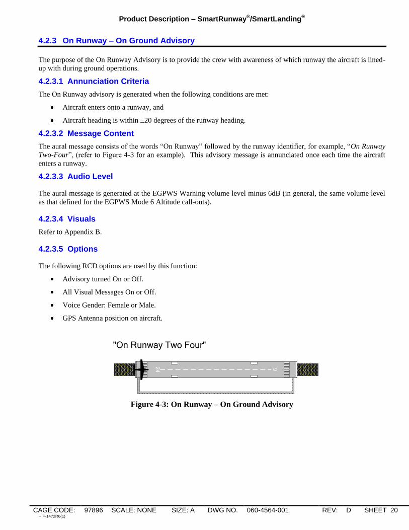
4.2.3 On Runway – On Ground Advisory
The purpose of the On Runway Advisory is to provide the crew with awareness of which runway the aircraft is lined-
up with during ground operations.
4.2.3.1 Annunciation Criteria
The On Runway advisory is generated when the following conditions are met:
Aircraft enters onto a runway, and
Aircraft heading is within 20 degrees of the runway heading.
4.2.3.2 Message Content
The aural message consists of the words “On Runway” followed by the runway identifier, for example, “On Runway
Two-Four”, (refer to Figure 4-3 for an example). This advisory message is annunciated once each time the aircraft
enters a runway.
4.2.3.3 Audio Level
The aural message is generated at the EGPWS Warning volume level minus 6dB (in general, the same volume level
as that defined for the EGPWS Mode 6 Altitude call-outs).
4.2.3.4 Visuals
Refer to Appendix B.
4.2.3.5 Options
The following RCD options are used by this function:
Advisory turned On or Off.
All Visual Messages On or Off.
Voice Gender: Female or Male.
GPS Antenna position on aircraft.
24 6
"On Runway Two Four"
Figure 4-3: On Runway – On Ground Advisory
Product Description – SmartRunway®/SmartLanding®
CAGE CODE: 97896 SCALE: NONE SIZE: A DWG NO. 060-4564-001 REV: D SHEET 21 HIF-1472R6(1)
4.2.4 Distance Remaining – Landing and Roll-Out Advisory
The purpose of the Distance Remaining advisories is to enhance crew awareness of aircraft along-track position
relative to the runway end.
4.2.4.1 Annunciation Criteria
The Distance Remaining advisory is generated when the following conditions are met:
Aircraft is within 100 feet of the ground, over the last half of the runway or a specified distance from the
runway end; or
Aircraft is on the ground, on the last half of the runway (default) or a specified distance from the runway end,
and
Aircraft ground speed is above 40 knots.
Refer to Figure 4-4. If the crew elects to go-around after the Distance Remaining advisories are triggered, the
advisories continue to be annunciated at the appropriate distances along the runway. The Distance Remaining
advisories are inhibited once the aircraft climbs above 100 feet Radio Altitude or aircraft climb rate is greater than
450 fpm.
4.2.4.2 Message Content For systems using feet as the unit of length, these advisories are generated at whole thousand-foot intervals, except
that the last possible advisory occurs at 500 feet. For example, a RAAS equipped aircraft landing on a 9000 foot
runway, configured with the Distance Remaining advisory issued at the last half of the runway, would generate the
following advisories: “Four-Thousand Remaining”, “Three-Thousand Remaining”, “Two-Thousand Remaining”,
“One-Thousand Remaining”, and “Five-Hundred Remaining”. A second example, of a RAAS equipped aircraft
configured landing on a 9000 foot runway, with the Distance Remaining advisory issued starting at 2000 feet from
the runway end, would generate the following advisories: “Two-Thousand Remaining”, “One-Thousand Remaining”,
and “Five-Hundred Remaining”.
For systems using meters as the unit of length, these advisories are generated at multiples of 300-meter intervals,
except that the last possible advisory occurs at 100 meters. For example, a RAAS equipped aircraft landing on a
3000 meter runway, with the Distance Remaining advisory issued at the last half of the runway, would generate the
following advisories: “One-Thousand-Two-Hundred Remaining”, “Nine-Hundred Remaining”, “Six-Hundred
Remaining”, “Three-Hundred Remaining”, and “One-Hundred Remaining”. A second example, of a RAAS
equipped aircraft configured landing on a 3000 meter runway, with the Distance Remaining advisory issued starting
at 900 meters from the runway end, would generate the following advisories: “Nine-Hundred Remaining”, “Six-
Hundred Remaining”, “Three-Hundred Remaining”, and “One-Hundred Remaining”.
If the RCD option to annunciate the unit of measurement is enabled, “Feet” or “Meters” will be included in the first
phrase. For example, “Three-Thousand Feet Remaining” followed by “Two-Thousand Remaining” and so on.
4.2.4.3 Audio Level
The aural message is generated at the same volume level as that defined for the EGPWS Cautions and Warnings.
4.2.4.4 Options
The following RCD options are used by this function:
Advisory turned On or Off.
Voice Gender: Female or Male.
Advisory issued at last half of runway or a specified distance from the runway end.
Distance remaining call-outs in Feet or Meters.
Include units voice (“feet” or “meters”) in first call-out.
GPS Antenna position on aircraft.

Product Description – SmartRunway®/SmartLanding®
CAGE CODE: 97896 SCALE: NONE SIZE: A DWG NO. 060-4564-001 REV: D SHEET 22 HIF-1472R6(1)
34L 1 6 R
34 L1
6R
10
00
20
00
30
00
40
00
50
00
60
00
70
00
80
00
50
0
10
0
"Four T
housa
nd R
em
ain
ing"
"Thre
e T
housa
nd R
em
ain
ing"
"Tw
o T
housa
nd R
em
ain
ing"
"One T
housa
nd R
em
ain
ing"
"Five
Hundre
d R
em
ain
ing"
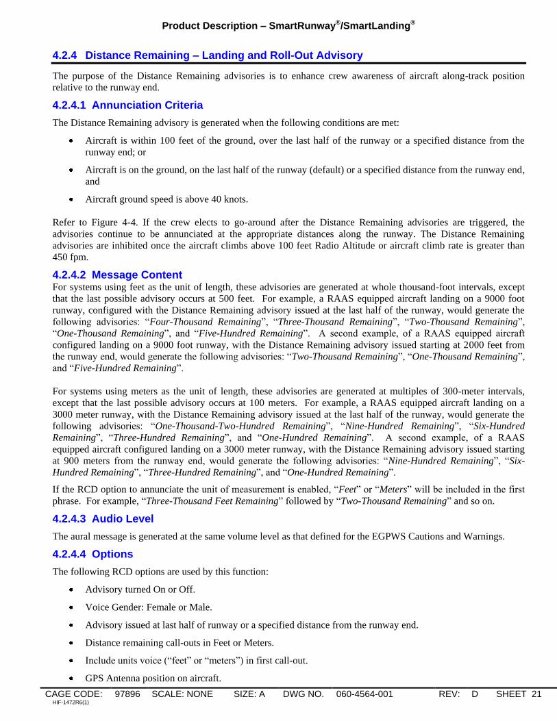
Figure 4-4: Distance Remaining – Landing and Roll – Out (in feet) Advisory
4.2.5 Runway End Advisory
The purpose of the Runway End Advisory is to improve flight crew awareness of the position of the aircraft relative
to the runway end during low visibility conditions.
4.2.5.1 Annunciation Criteria
This advisory is provided to the flight crew when:
Aircraft is on a runway and aligned within 20 degrees of runway heading, and
Aircraft approaches within 100 feet of the runway end; and
Aircraft ground speed is below 40 Knots.
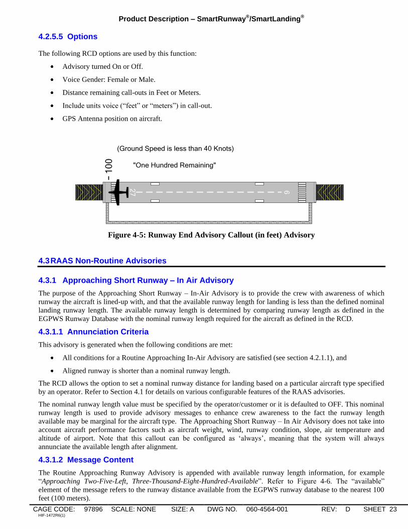
4.2.5.2 Message Content
The aural message is “One-Hundred Remaining” for units of feet and “Thirty Remaining” for units of meters. Refer
to Figure 4-5.
If the RCD option to annunciate the unit of measurement is enabled, “Feet” or “Meters” will be included in the
phrase. For example, “One-Hundred Feet Remaining” for units of feet, and “Thirty Meters Remaining” for units of
meters.
4.2.5.3 Audio Level
The aural message is generated at the EGPWS Warning volume level minus 6dB (in general, the same volume level
as that defined for the EGPWS Mode 6 Altitude call-outs).
4.2.5.4 Visuals
Refer to Appendix B.
Product Description – SmartRunway®/SmartLanding®
CAGE CODE: 97896 SCALE: NONE SIZE: A DWG NO. 060-4564-001 REV: D SHEET 23 HIF-1472R6(1)
4.2.5.5 Options
The following RCD options are used by this function:
Advisory turned On or Off.
Voice Gender: Female or Male.
Distance remaining call-outs in Feet or Meters.
Include units voice (“feet” or “meters”) in call-out.
GPS Antenna position on aircraft.
27 9
(Ground Speed is less than 40 Knots)
"One Hundred Remaining"
10
0
Figure 4-5: Runway End Advisory Callout (in feet) Advisory
4.3 RAAS Non-Routine Advisories
4.3.1 Approaching Short Runway – In Air Advisory
The purpose of the Approaching Short Runway – In-Air Advisory is to provide the crew with awareness of which
runway the aircraft is lined-up with, and that the available runway length for landing is less than the defined nominal
landing runway length. The available runway length is determined by comparing runway length as defined in the
EGPWS Runway Database with the nominal runway length required for the aircraft as defined in the RCD.
4.3.1.1 Annunciation Criteria
This advisory is generated when the following conditions are met:
All conditions for a Routine Approaching In-Air Advisory are satisfied (see section 4.2.1.1), and
Aligned runway is shorter than a nominal runway length.
The RCD allows the option to set a nominal runway distance for landing based on a particular aircraft type specified
by an operator. Refer to Section 4.1 for details on various configurable features of the RAAS advisories.
The nominal runway length value must be specified by the operator/customer or it is defaulted to OFF. This nominal
runway length is used to provide advisory messages to enhance crew awareness to the fact the runway length
available may be marginal for the aircraft type. The Approaching Short Runway – In Air Advisory does not take into
account aircraft performance factors such as aircraft weight, wind, runway condition, slope, air temperature and
altitude of airport. Note that this callout can be configured as „always‟, meaning that the system will always
annunciate the available length after alignment.
4.3.1.2 Message Content
The Routine Approaching Runway Advisory is appended with available runway length information, for example
“Approaching Two-Five-Left, Three-Thousand-Eight-Hundred-Available”. Refer to Figure 4-6. The “available”
element of the message refers to the runway distance available from the EGPWS runway database to the nearest 100
feet (100 meters).

Product Description – SmartRunway®/SmartLanding®
CAGE CODE: 97896 SCALE: NONE SIZE: A DWG NO. 060-4564-001 REV: D SHEET 24 HIF-1472R6(1)
This advisory occurs once for each runway alignment based on the conditions specified in section 4.2.1 above. For
example, if the aircraft aligns with a “normal” length runway followed by a side-step to a short runway, while still
meeting the altitude requirements in section 4.2.1.1, two Approaching Runway advisories would be heard; the first a
routine, “Approaching Two-Five-Right” the second, a non-routine, “Approaching Two-Five-Left, Three-Thousand-
Eight-Hundred Available”.
If the RCD option to annunciate the unit of measurement is enabled, “Feet” or “Meters” will be included in the
phrase. For example, “Approaching Two-Five-Left, Three-Thousand-Eight-Hundred Feet Available”.
4.3.1.3 Audio Level
The aural message is generated at the EGPWS Warning volume level minus 6dB (in general, the same volume level
as that defined for the EGPWS Mode 6 Altitude call-outs).
4.3.1.4 Visuals
Refer to Appendix B.
4.3.1.5 Options
The following RCD options are used by this function:
Advisory turned On or Off.
Voice Gender: Female or Male.
Distance remaining call-outs in Feet or Meters.
Include units voice (“feet” or “meters”) in call-out.
GPS Antenna position on aircraft.
All Visual Messages On or Off, or Non-Routine Visual Messages Only On.
Nominal runway length to trigger the advisory or it may be configured to always annunciate the runway
length available.
NOTES:
1) The Approaching Short Runway – In Air advisory uses the same advisory suppression window selected for Approaching Runway In-Air
advisory, Section 4.2. Either 550 – 450 feet AFE or 450 – 350 feet AFE.
2) The default setting for this advisory is Off. In order to activate it, the advisory must be turned On and the nominal runway length or
“always” specified in the RCD.
3) The RCD can be programmed to support multiple nominal runway lengths based on individual aircraft type. This allows a single RCD
load to be used across an entire airline fleet. Refer to Section 4.1 and Appendix B for details.

Product Description – SmartRunway®/SmartLanding®
CAGE CODE: 97896 SCALE: NONE SIZE: A DWG NO. 060-4564-001 REV: D SHEET 25 HIF-1472R6(1)
7L
25 R
7 L25R
10
00
20
00
30
00
40
00
50
00
60
00
70
00
80
00
50
0
10
0
"Approaching Two Five Right"
5.2fig.vsd
2-12-2003"Approaching Two Five Left,
Three Thousand Eight Hundred
Available"
Figure 4-6: Approaching Short Runway – In Air Advisory
4.3.2 Approaching Short Runway – In Air Caution
The purpose of this annunciation is to provide the crew with immediate awareness that the available runway length
for landing is still less than the defined nominal runway length when the approach is continued as noted below after
the available runway length for landing has been provided.
The available runway length is determined by comparing runway length as defined in the EGPWS Runway Database
with the nominal runway length required for the aircraft as defined in the RCD.
The selection of the caution, in addition to the existing advisory, is configurable via the RCD.
If the caution is desired, it is recommended that both the advisory and caution be enabled.
4.3.2.1 Annunciation Criteria
The Approaching Short Runway – In Air Caution is generated when the following conditions are met:
All conditions for an Approaching Short In-Air Advisory are satisfied (see section 4.3.1.1), and
Aligned runway is shorter than a nominal runway length, and
Aircraft is below the RAAS Advisory Suppress Window (either 450 feet or 350 feet) and more than 300 feet
above the airport elevation (AFE).
The RCD allows the option to set a nominal runway distance for landing based on a particular aircraft type specified
by an operator. Refer to section 4.1 for details on various configurable features of the routine and non-routine
advisories.
The nominal runway length value must be specified by the operator/customer or it is defaulted to OFF. This nominal
runway length is used to provide advisory messages to enhance crew awareness to the fact the runway length
available may be marginal for the aircraft type. The Approaching Short Runway – In Air Caution does not take into
account aircraft performance factors such as aircraft weight, wind, runway condition, slope, air temperature and
altitude of airport.
4.3.2.2 Message Content
The Approaching Short Runway – In Air Caution aural message is “Caution Short Runway, Short Runway. Refer to
Figure 4-7.

Product Description – SmartRunway®/SmartLanding®
CAGE CODE: 97896 SCALE: NONE SIZE: A DWG NO. 060-4564-001 REV: D SHEET 26 HIF-1472R6(1)
4.3.2.3 Audio Level
The aural message is generated at the EGPWS Warning volume.
4.3.2.4 Visuals
Refer to Appendix B.
4.3.2.5 Options
The following RCD options are used by this function:
Caution turned On or Off.
Voice Gender: Female or Male.
GPS Antenna position on aircraft.
All Visual Messages On or Off, Non-Routine Visual Messages Only On, or Caution Visual Messages Only
On.
Nominal runway length to trigger the caution.
NOTES:
1) The default setting for this caution is Off. In order to activate it, the caution must be turned On and the nominal runway length specified
in the RCD.
2) The RCD can be programmed to support multiple nominal runway lengths based on individual aircraft type. This allows a single RCD
load to be used across an entire airline fleet. Refer to section 4.1 and Appendix B for details.
7L
25 R
7 L25R
10
00
20
00
30
00
40
00
50
00
60
00
70
00
80
00
50
0
10
0
"Approaching Two Five Right"
5.2fig.vsd
2-12-2003
"Approaching Two Five Left,
Three Thousand Eight Hundred Available",
“Caution Short Runway, Short Runway”
Figure 4-7: Approaching Short Runway – In Air Caution

Product Description – SmartRunway®/SmartLanding®
CAGE CODE: 97896 SCALE: NONE SIZE: A DWG NO. 060-4564-001 REV: D SHEET 27 HIF-1472R6(1)
4.3.3 Insufficient Runway Length – On-Ground Advisory
The purpose of the Insufficient Runway Length – On-Ground Advisory is to provide the crew with awareness of
which runway the aircraft is lined-up with, and that the runway length available for takeoff is less than the defined
nominal takeoff runway length. The available runway length is determined by comparing the aircraft‟s position on
the runway with the distance available as defined in the EGPWS Runway Database.
4.3.3.1 Annunciation Criteria
This advisory is generated when the following conditions are met:
All conditions for a routine On-Runway Advisory are satisfied, and
Available distance for takeoff is less than the defined nominal runway length.
The RCD allows the option to set a “nominal” runway distance for take-off based on a particular aircraft type
specified by an operator. Refer to section 4.1 for more details. If the operator does not specify the nominal runway
length the advisory is defaulted to off. Once again, note that this advisory does not take into account aircraft
performance factors such as aircraft weight, wind, runway condition, slope air temperature and altitude of airport.
Note that this callout can be configured as „always‟, meaning that the system will always annunciate the available
length after alignment.
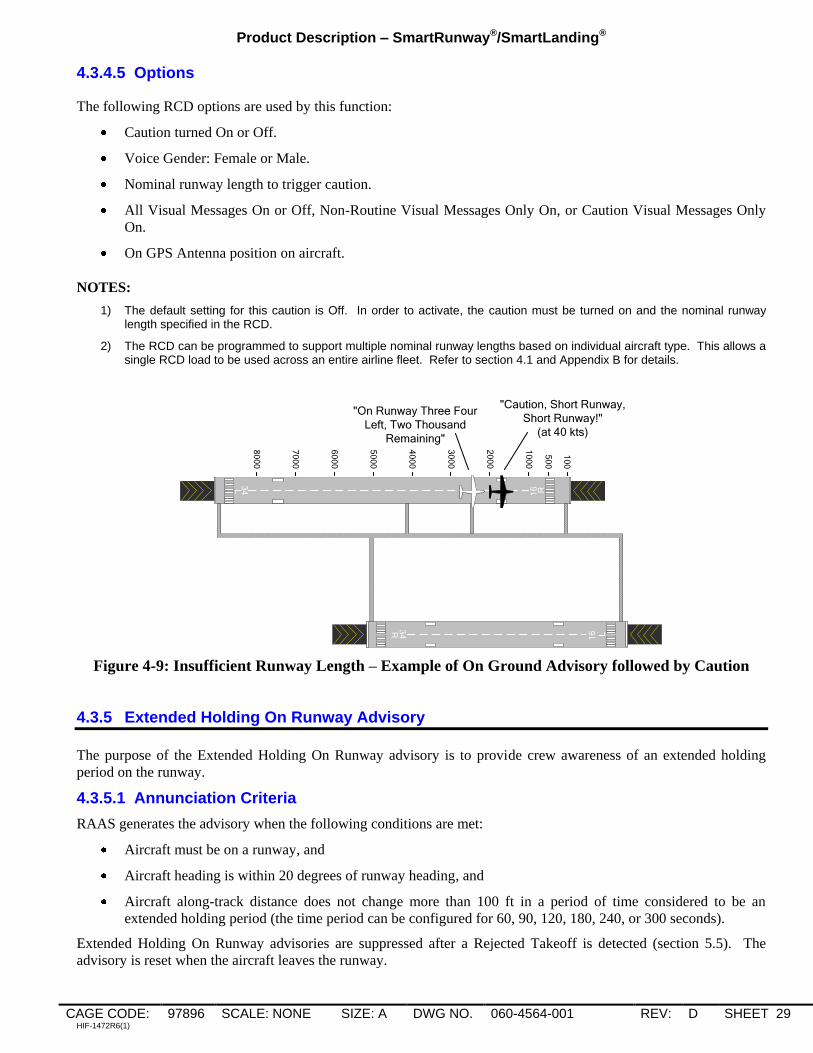
4.3.3.2 Message Content
Runway length remaining information is appended to the routine “On Runway” advisory. For example: “On
Runway Three-Four-Left, Two-Thousand Remaining”. Refer to Figure 4-8. The “remaining” element of the message
refers to the runway distance available from the EGPWS runway database to the nearest 100 feet (100 meters).
If the RCD option to annunciate the unit of measurement is enabled, “Feet” or “Meters” will be included in the
phrase. For example, “On Runway Three-Four-Left, Two-Thousand Feet Remaining”.
4.3.3.3 Audio Level
The aural message is generated at the EGPWS Warning volume level minus 6dB (in general, the same volume level
as that defined for the EGPWS Mode 6 Altitude call-outs).
4.3.3.4 Visuals
Refer to Appendix B.
4.3.3.5 Options
The following RCD options are used by this function:
Advisory turned On or Off
Voice Gender: Female or Male.
Runway length remaining information in Feet or Meters.
Include units voice (“feet” or “meters”) in call-out.
GPS Antenna position on aircraft.
All Visual Messages On or Off, or Non-Routine Visual Messages Only On.
Nominal runway length to trigger advisory or it may be configured to always annunciate the runway length
available.
NOTES:
1) The default setting for this advisory is Off. In order to activate, the advisory must be turned On and the nominal runway length or
“always” specified in the RCD.
2) The RCD can be programmed to support multiple nominal runway lengths based on aircraft type. This allows a single RCD load to be
used across an entire airline fleet. Refer to section 4.1 and Appendix B for details.

Product Description – SmartRunway®/SmartLanding®
CAGE CODE: 97896 SCALE: NONE SIZE: A DWG NO. 060-4564-001 REV: D SHEET 28 HIF-1472R6(1)
34L
16 R
34 L1
6R
10
00
20
00
30
00
40
00
50
00
60
00
70
00
80
00
50
0
10
0
"On Runway Three Four Left, Two Thousand Remaining"
Figure 4-8: Insufficient Runway Length – On Ground Advisory
4.3.4 Insufficient Runway Length – On-Ground Caution
The purpose of this annunciation is to provide the crew with immediate awareness that the runway length available
for takeoff is still less than the defined nominal takeoff runway length when the takeoff is continued as noted below
after the remaining runway length for takeoff has been provided.
The available runway length is determined by comparing the aircraft‟s position on the runway with the distance
available as defined in the EGPWS Runway Database.
The selection of the caution, in addition to the existing advisory, is configurable via the RCD.
If the caution is desired, it is recommended that both the advisory and caution be enabled.
4.3.4.1 Annunciation Criteria
The Insufficient Runway – On-Ground Caution is generated when the following conditions are met:
All conditions for a routine On-Runway Advisory are satisfied (section 4.2.3), and
Available distance for takeoff is less than the defined nominal runway length, and
Aircraft ground speed transitions to above 40 knots.
The RCD allows the option to set a “nominal” runway distance for take-off based on a particular aircraft type
specified by an operator. Refer to section 4.1 for more details. If the operator does not specify the nominal runway
length the advisory is defaulted to off. Once again, note that this annunciation does not take into account aircraft
performance factors such as aircraft weight, wind, runway condition, slope air temperature and altitude of airport.
4.3.4.2 Message Content
The Insufficient Runway Length – On-Ground Caution aural message is “Caution Short Runway, Short Runway”.
Refer to Figure 4-9.
4.3.4.3 Audio Level
The aural message is generated at the EGPWS Warning volume.
4.3.4.4 Visuals
Refer to Appendix B.
Product Description – SmartRunway®/SmartLanding®
CAGE CODE: 97896 SCALE: NONE SIZE: A DWG NO. 060-4564-001 REV: D SHEET 29 HIF-1472R6(1)
4.3.4.5 Options
The following RCD options are used by this function:
Caution turned On or Off.
Voice Gender: Female or Male.
Nominal runway length to trigger caution.
All Visual Messages On or Off, Non-Routine Visual Messages Only On, or Caution Visual Messages Only
On.
On GPS Antenna position on aircraft.
NOTES:
1) The default setting for this caution is Off. In order to activate, the caution must be turned on and the nominal runway length specified in the RCD.
2) The RCD can be programmed to support multiple nominal runway lengths based on individual aircraft type. This allows a single RCD load to be used across an entire airline fleet. Refer to section 4.1 and Appendix B for details.
34L
16 R
34 L1
6R
10
00
20
00
30
00
40
00
50
00
60
00
70
00
80
00
50
0
10
0
"On Runway Three Four
Left, Two Thousand
Remaining"
"Caution, Short Runway,
Short Runway!"
(at 40 kts)
Figure 4-9: Insufficient Runway Length – Example of On Ground Advisory followed by Caution
4.3.5 Extended Holding On Runway Advisory
The purpose of the Extended Holding On Runway advisory is to provide crew awareness of an extended holding
period on the runway.
4.3.5.1 Annunciation Criteria
RAAS generates the advisory when the following conditions are met:
Aircraft must be on a runway, and
Aircraft heading is within 20 degrees of runway heading, and
Aircraft along-track distance does not change more than 100 ft in a period of time considered to be an
extended holding period (the time period can be configured for 60, 90, 120, 180, 240, or 300 seconds).
Extended Holding On Runway advisories are suppressed after a Rejected Takeoff is detected (section 5.5). The
advisory is reset when the aircraft leaves the runway.

Product Description – SmartRunway®/SmartLanding®
CAGE CODE: 97896 SCALE: NONE SIZE: A DWG NO. 060-4564-001 REV: D SHEET 30 HIF-1472R6(1)
4.3.5.2 Message Content
After the specified time period has expired, RAAS generates an advisory that consists of the aural message “On
Runway” followed by the runway identifier. This advisory is annunciated twice for each time interval. For example,
if an aircraft is cleared to line-up-and-wait on runway 22 and, after waiting in position for an extended period, say 90
seconds, the system will annunciate “On Runway Two-Two, On Runway Two-Two”.
If the aircraft continues to hold for another period of time, which may be set for the same time interval or a different
time interval, the above message would repeat. The repeat advisory time may also be configured to be OFF. (See
NOTE below).
4.3.5.3 Audio Level
The aural message is generated at the EGPWS Warning volume level minus 6dB (in general, the same volume level
as that defined for the EGPWS Mode 6 Altitude call-outs).
4.3.5.4 Visuals
Refer to Appendix B.
4.3.5.5 Options
The following RCD options are used by this function:
Advisory turned On or Off
Voice Gender: Female or Male.
INITIAL advisory time (seconds): 60, 90 (default), 120, 180, 240, 300, OFF.
REPEAT advisory time (seconds): 30, 60, 90, 120 (default), 180, 240, 300, OFF.
All Visual Messages On or Off, or Non-Routine Visual Messages Only On.
GPS Antenna position on aircraft.
NOTE: If OFF is selected for INITIAL advisory time, then no repeat advisory is issued. The REPEAT advisory time can be
turned OFF so that only an INITIAL advisory message is issued (i.e. one message for each occurrence with no follow
on messages).
4.3.6 Taxiway Take-Off
4.3.6.1 Taxiway Take-Off Advisory
The purpose of the Taxiway Take-Off advisory is to enhance crew awareness of excessive taxi speeds or an
inadvertent take-off on a taxiway.
4.3.6.1.1 Annunciation Criteria The advisory is generated if:
Ground speed of the aircraft exceeds 40 knots, and
Aircraft is not aligned with a runway.
NOTE: RAAS functions are based on a database of runway locations. The system does not have knowledge of the
location of taxiways.
4.3.6.1.2 Message Content The aural message string “On Taxiway! On Taxiway!” is annunciated once each time the advisory is generated. Refer
to Figure 4-10.
4.3.6.1.3 Audio Level
The aural message is generated at the EGPWS Cautions and Warnings volume level plus 3dB.

Product Description – SmartRunway®/SmartLanding®
CAGE CODE: 97896 SCALE: NONE SIZE: A DWG NO. 060-4564-001 REV: D SHEET 31 HIF-1472R6(1)
4.3.6.1.4 Visuals
Refer to Appendix B.
4.3.6.1.5 Options
The following RCD options are used by this function:
Advisory turned On or Off
Voice Gender: Female or Male.
All Visual Messages On or Off, or Non-Routine Visual Messages Only On.
GPS Antenna position on aircraft.
27 9
(Ground Speed is Greater than 40 Knots)
"On Taxiway! On Taxiway!"
Figure 4-10: Taxiway Take-Off Advisory
4.3.6.2 Taxiway Take-Off Caution
It may be desired to classify the Taxiway take off as a Caution condition. This is done via the RCD. The caution
criteria and audio level are the same as described in section 4.3.6.1 for the advisory. The visual is different (refer to
Appendix B).
4.3.6.2.1 Message Content The aural message string “Caution, On Taxiway! On Taxiway!” is annunciated once each time the caution is
generated. Refer to Figure 4-11.
4.3.6.2.2 Options
The following RCD options are used by this function:
Taxiway Takeoff Caution turned On or Off
Voice Gender: Female or Male.
All Visual Messages On or Off, Non-Routine Visual Messages Only On, or Caution Visual Messages Only
On.
GPS Antenna position on aircraft.
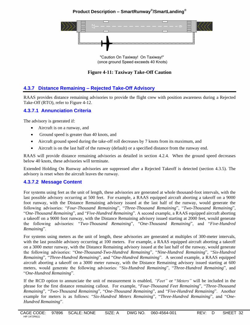
Product Description – SmartRunway®/SmartLanding®
CAGE CODE: 97896 SCALE: NONE SIZE: A DWG NO. 060-4564-001 REV: D SHEET 32 HIF-1472R6(1)
27 9
"Caution On Taxiway! On Taxiway!"
(once ground Speed exceeds 40 Knots)
Figure 4-11: Taxiway Take-Off Caution
4.3.7 Distance Remaining – Rejected Take-Off Advisory
RAAS provides distance remaining advisories to provide the flight crew with position awareness during a Rejected
Take-Off (RTO), refer to Figure 4-12.
4.3.7.1 Annunciation Criteria
The advisory is generated if:
Aircraft is on a runway, and
Ground speed is greater than 40 knots, and
Aircraft ground speed during the take-off roll decreases by 7 knots from its maximum, and
Aircraft is on the last half of the runway (default) or a specified distance from the runway end.
RAAS will provide distance remaining advisories as detailed in section 4.2.4. When the ground speed decreases
below 40 knots, these advisories will terminate.
Extended Holding On Runway advisories are suppressed after a Rejected Takeoff is detected (section 4.3.5). The
advisory is reset when the aircraft leaves the runway.
4.3.7.2 Message Content
For systems using feet as the unit of length, these advisories are generated at whole thousand-foot intervals, with the
last possible advisory occurring at 500 feet. For example, a RAAS equipped aircraft aborting a takeoff on a 9000
foot runway, with the Distance Remaining advisory issued at the last half of the runway, would generate the
following advisories: “Four-Thousand Remaining”, “Three-Thousand Remaining”, “Two-Thousand Remaining”,
“One-Thousand Remaining”, and “Five-Hundred Remaining”. A second example, a RAAS equipped aircraft aborting
a takeoff on a 9000 foot runway, with the Distance Remaining advisory issued starting at 2000 feet, would generate
the following advisories: “Two-Thousand Remaining”, “One-Thousand Remaining”, and “Five-Hundred
Remaining”.
For systems using meters as the unit of length, these advisories are generated at multiples of 300-meter intervals,
with the last possible advisory occurring at 100 meters. For example, a RAAS equipped aircraft aborting a takeoff
on a 3000 meter runway, with the Distance Remaining advisory issued at the last half of the runway, would generate
the following advisories: “One-Thousand-Two-Hundred Remaining”, “Nine-Hundred Remaining”, “Six-Hundred
Remaining”, “Three-Hundred Remaining”, and “One-Hundred Remaining”. A second example, a RAAS equipped
aircraft aborting a takeoff on a 3000 meter runway, with the Distance Remaining advisory issued starting at 600
meters, would generate the following advisories: “Six-Hundred Remaining”, “Three-Hundred Remaining”, and
“One-Hundred Remaining”.
If the RCD option to annunciate the unit of measurement is enabled, “Feet” or “Meters” will be included in the
phrase for the first distance remaining callout. For example, “Four-Thousand Feet Remaining”, “Three-Thousand
Remaining”, “Two-Thousand Remaining”, “One-Thousand Remaining”, and “Five-Hundred Remaining”. Another
example for meters is as follows: “Six-Hundred Meters Remaining”, “Three-Hundred Remaining”, and “One-
Hundred Remaining”.

Product Description – SmartRunway®/SmartLanding®
CAGE CODE: 97896 SCALE: NONE SIZE: A DWG NO. 060-4564-001 REV: D SHEET 33 HIF-1472R6(1)
4.3.7.3 Audio level
The aural message is generated at the EGPWS Cautions and Warnings volume level.
4.3.7.4 Visuals
There are no visuals associated with this function.
4.3.7.5 Options
The following RCD options are used by this function:
Advisory turned On or Off
Voice Gender: Female or Male.
Distance call-outs in Feet or Meters.
Include units voice (“feet” or “meters”) in first call-out.
Advisory issued at last half of runway or a specified distance from the runway end.
GPS Antenna position on aircraft.
34L
16 R
34 L1
6R
10
00
20
00
30
00
40
00
50
00
60
00
70
00
80
00
50
0
10
0
"Four Thousand Remaining"
"Three Thousand Remaining"
"Two Thousand Remaining"
1. Aircraft accelerates on runway, ground speed exceeds 40 Knots.
2. Aircraft Ground speed decreases by 7 knots, the aircraft is on the last half of the runway,
and the ground speed is above 40 Knots.
3. Distance remaining callouts continue until the aircraft ground speed is less than 40 Knots.
1. 3.2.
Figure 4-12: Rejected Take-Off, Distance Remaining Advisory

Product Description – SmartRunway®/SmartLanding®
CAGE CODE: 97896 SCALE: NONE SIZE: A DWG NO. 060-4564-001 REV: D SHEET 34 HIF-1472R6(1)
4.3.8 Taxiway Landing
The purpose of the Taxiway Landing caution is to provide crew awareness that the aircraft is not lined up with a
runway at low altitudes.
4.3.8.1 Annunciation Criteria
The caution is generated if:
Aircraft is airborne between 150 and 250 feet AGL (Radio Altitude), and
Aircraft climb rate is less than 450 FPM, and
Aircraft is within 5 NM of a runway and is not lined-up with a runway.
NOTE: RAAS functions are based on a database of runway locations. The system does not have knowledge of the
location of taxiways.
4.3.8.2 Message Content
The aural message string “Caution Taxiway, Caution Taxiway” is annunciated once each time the caution is
generated. Refer to Figure 4-13.
4.3.8.3 Audio Level
The aural message is generated at the EGPWS Cautions and Warnings volume level.
4.3.8.4 Visuals
Refer to Appendix B.
4.3.8.5 Options
The following RCD options are used by this function:
Caution turned On or Off
Voice Gender: Female or Male.
All Visual Messages On or Off, Non-Routine Visual Messages Only On, or Caution Visual Messages Only
On.
GPS Antenna position on aircraft.
"Caution Taxiway!
Caution Taxiway!"
Figure 4-13: Taxiway Landing Caution
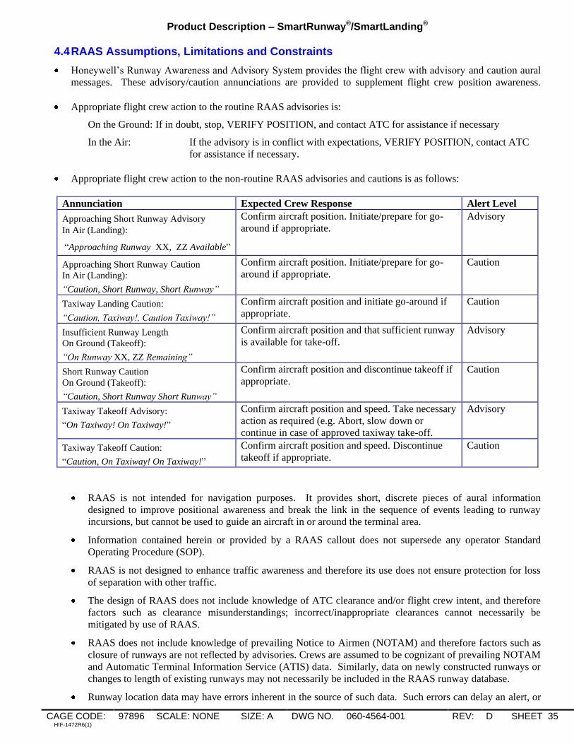
Product Description – SmartRunway®/SmartLanding®
CAGE CODE: 97896 SCALE: NONE SIZE: A DWG NO. 060-4564-001 REV: D SHEET 35 HIF-1472R6(1)
4.4 RAAS Assumptions, Limitations and Constraints
Honeywell‟s Runway Awareness and Advisory System provides the flight crew with advisory and caution aural
messages. These advisory/caution annunciations are provided to supplement flight crew position awareness.
Appropriate flight crew action to the routine RAAS advisories is:
On the Ground: If in doubt, stop, VERIFY POSITION, and contact ATC for assistance if necessary
In the Air: If the advisory is in conflict with expectations, VERIFY POSITION, contact ATC
for assistance if necessary.
Appropriate flight crew action to the non-routine RAAS advisories and cautions is as follows:
Annunciation Expected Crew Response Alert Level
Approaching Short Runway Advisory
In Air (Landing):
“Approaching Runway XX, ZZ Available”
Confirm aircraft position. Initiate/prepare for go-
around if appropriate.
Advisory
Approaching Short Runway Caution
In Air (Landing):
“Caution, Short Runway, Short Runway”
Confirm aircraft position. Initiate/prepare for go-
around if appropriate.
Caution
Taxiway Landing Caution:
“Caution, Taxiway!, Caution Taxiway!”
Confirm aircraft position and initiate go-around if
appropriate.
Caution
Insufficient Runway Length
On Ground (Takeoff):
“On Runway XX, ZZ Remaining”
Confirm aircraft position and that sufficient runway
is available for take-off.
Advisory
Short Runway Caution
On Ground (Takeoff):
“Caution, Short Runway Short Runway”
Confirm aircraft position and discontinue takeoff if
appropriate.
Caution
Taxiway Takeoff Advisory:
“On Taxiway! On Taxiway!”
Confirm aircraft position and speed. Take necessary
action as required (e.g. Abort, slow down or
continue in case of approved taxiway take-off.
Advisory
Taxiway Takeoff Caution:
“Caution, On Taxiway! On Taxiway!”
Confirm aircraft position and speed. Discontinue
takeoff if appropriate.
Caution
RAAS is not intended for navigation purposes. It provides short, discrete pieces of aural information
designed to improve positional awareness and break the link in the sequence of events leading to runway
incursions, but cannot be used to guide an aircraft in or around the terminal area.
Information contained herein or provided by a RAAS callout does not supersede any operator Standard
Operating Procedure (SOP).
RAAS is not designed to enhance traffic awareness and therefore its use does not ensure protection for loss
of separation with other traffic.
The design of RAAS does not include knowledge of ATC clearance and/or flight crew intent, and therefore
factors such as clearance misunderstandings; incorrect/inappropriate clearances cannot necessarily be
mitigated by use of RAAS.
RAAS does not include knowledge of prevailing Notice to Airmen (NOTAM) and therefore factors such as
closure of runways are not reflected by advisories. Crews are assumed to be cognizant of prevailing NOTAM
and Automatic Terminal Information Service (ATIS) data. Similarly, data on newly constructed runways or
changes to length of existing runways may not necessarily be included in the RAAS runway database.
Runway location data may have errors inherent in the source of such data. Such errors can delay an alert, or

Product Description – SmartRunway®/SmartLanding®
CAGE CODE: 97896 SCALE: NONE SIZE: A DWG NO. 060-4564-001 REV: D SHEET 36 HIF-1472R6(1)
may cause unwanted alerts.
RAAS callouts do not ensure that the aircraft will, or can be, stopped before hold lines, the runway edges or
the runway end.
RAAS distance advisories do not imply that the aircraft can or cannot be safely landed, stopped, or taken off
from a runway.
RAAS “On Taxiway” alerts do not insure that the aircraft is actually on a taxiway. For example, excessive
ground speeds in areas such as ramps will also trigger the On Taxiway alert.
RAAS in air “Approaching Runway” advisories do not ensure that the aircraft will land on the identified
runway.
The absence of an Approaching Runway In-Air advisory does not necessarily imply that the aircraft is
approaching a surface other than a runway.
RAAS may become Not Available at any time due to loss of accuracy of GPS signals.
Other EGPWS aural alerts and warnings may preempt RAAS advisories. RAAS advisories may be issued
during ATC radio communications, flight crew / cockpit communications, or during other aural messages
provided in the cockpit by other aircraft systems.

Product Description – SmartRunway®/SmartLanding®
CAGE CODE: 97896 SCALE: NONE SIZE: A DWG NO. 060-4564-001 REV: D SHEET 37 HIF-1472R6(1)
5. Stabilized Approach Monitor
The Stabilized Approach Monitor is intended to inform the flight crew of awareness of unstabilized approaches and
thus reduce landing risks and potential runway excursions.
5.1 Stabilized Approach Monitor Availability and Options
5.1.1 Stabilized Approach Monitor Operational Availability
Stabilized Approach Monitor function is operationally available anytime the EGPWS is powered and the following
conditions are met:
For MKV and MKVII EGPWS: Software Version 230-230 or later with a serial number EGPWC unit that
has been enabled to use the functions described in this document (this is referred to as the „Enable Key being
Set‟), or EGPWS Software Version 965-1690-054 or later with the Enable Key Set, or 965-1676-004 or later
with the Enable Key Set. For MKV-A EGPWS: software version 01.01 or later and Enable Key Set, or
software version 51.01 or later and Enable Key Set. Refer to section 9.1 for more information on the Enable
Key.
NOTE: Use of the Excessive Speed Monitor may require use of MKV-A EGPWS, or MKV/MKVII
EGPWS Software Version 232-232, or 965-1690-055, or 965-1676-005 or later. Refer to Appendix G
for more information.
Terrain Database 454 or later. Note that a S/W mod may be required in order to use databases 456 and later – refer to
section 4.1.1 for more information.
The Stabilized Approach Monitor options have been loaded via an RCD into the EGPWC.
Each enabled Stabilized Approach Monitor is functional (e.g. all external signals are available and not
faulted and there are no internal EGPWC faults).
For the Too High Function, the selected destination runway for the Runway Data (loaded as part of the
Terrain Database) contains validated Runway elevations and endpoints.
For the Too High Function, the selected destination runway is not indeterminate. Note: Indeterminate in this
context refers to closely spaced parallel runways, where the approach ends of the runways are not adjacent,
such that the distance from the aircraft to each runway‟s threshold is significantly different.
Stabilized Approach Monitor Availability is integrated into the existing EGPWS fault monitoring and Self-Test
functions.
For software versions prior to 965-0976-236-236, 965-1676-006, and 965-1690-057, an Aircraft Type option
via the RCD is available to drive the GPWS INOP visual with the Stabilized Approach Monitor status should
this be required for a given design.
For the MKV-A EGPWS, and MKV/MKVII EGPWS Software versions 965-0976-236-236, 965-1676-006,
and 965-1690-057 and later:
The EGPWS also provides RAAS Monitor discrete output as well as ARINC 429 RAAS INOP and RAAS
Not Available outputs.
The RAAS Monitor discrete will be active if any RCD enabled monitoring function (RAAS, Long
Landing, Stabilized Approach, Altimeter, Takeoff Flap) becomes inoperative or not available. This
discrete may be used to drive a dedicated RAAS INOP / Not Available lamp. Note to maintain backward
compatibility that the system can be configured via the RCD to activate the GPWS INOP for RAAS INOP
conditions.
The ARINC 429 RAAS INOP will be active if any RCD enabled monitor function becomes INOP.
Similarly the ARINC 429 RAAS Not Available will become active if any RCD enabled monitor function
is not available. If supported by Crew Alerting System (CAS) these labels may be used to drive dedicated
RAAS INOP or RAAS Not Available CAS messages.

Product Description – SmartRunway®/SmartLanding®
CAGE CODE: 97896 SCALE: NONE SIZE: A DWG NO. 060-4564-001 REV: D SHEET 38 HIF-1472R6(1)
Consistent with approved EGPWS Self-Test design, the loss of the Stabilized Approach Monitor function will be
indicated on-ground during a level 1 Self-Test. Refer to Appendix C for a list of Self-Test maintenance messages.
5.1.2 EGPWS Runway Database
Current EGPWS databases contain airport and runway information. However, to ensure optimal Excessive Approach
Angle Monitor performance, the accuracy of this data is re-verified and validated before the function can use the
data. EGPWS Terrain database 454 and later contains additional airport and runway information that this monitor
uses to determine if it can perform its intended function.
5.1.3 Signals Required
5.1.3.1 GPS Signals Required, Accuracy and Availability
Some of the Stabilized Approach Monitors require a high level of GPS position accuracy to function. GPS receivers
used to provide position information must have a position resolution of 300 feet or better. Most ARINC 743/743A
GPS systems provide this resolution. The internal GPS receivers used with the EGPWS provide the needed accuracy
and resolution.
The Stabilized Approach Monitor does not require WAAS or Differential GPS (DGPS). However, either or both
could enhance position accuracy of standard GPS data. The function monitors GPS accuracy and will automatically
become Not Available if the accuracy degrades below acceptable limits. Factors which could degrade GPS accuracy
include intentional accuracy degradation (Selective Availability activated), signal multipath, ionospheric and
tropospheric delays, satellite geometry and shading, and system errors such as clock inaccuracies, etc.
5.1.3.2 Approach Speed
Approach Speed is required for the Excessive Approach Speed Monitor function. This data can come from displays
or FMS, and must be configured to be received by the EGPWS aircraft type in order for the function to be enabled.
5.1.3.3 Other Required Signals
All other signals required for the Stabilized Approach Monitor are currently available from aircraft equipped with an
EGPWS.
5.1.4 Stabilized Approach Monitor Options Summary
The option for a separate cockpit selection to inhibit the Stabilized Approach Monitor or to configure an existing
cockpit selection (RAAS Inhibit) to inhibit the Stabilized Approach Monitor annunciations can be enabled via the
RCD. The Stabilized Approach Monitor annunciations are single-shot and will only be activated in abnormal flight
conditions.
Global Options are applicable for all Stabilized Approach Monitor advisories/cautions and will be the same for all
aircraft types programmed in the RCD. For example, Stabilized Approach Monitor aural annunciations may be
specified to be a Male or Female voice. If the Male voice is selected, all Stabilized Approach Monitor annunciations
will use the Male voice. If one advisory is set to Male, another cannot be set to Female.
Aircraft-Type Specific options can be selected differently between various aircraft types specified in the RCD. The
following table indicates which options are global and which are aircraft specific.

Product Description – SmartRunway®/SmartLanding®
CAGE CODE: 97896 SCALE: NONE SIZE: A DWG NO. 060-4564-001 REV: D SHEET 39 HIF-1472R6(1)
Table 5-1: Stabilzed Approach Monitior Options
DESCRIPTION Global
Option
A/C
Type
Specific
Option
SELECTIONS REF
SECTION
Voice Gender X MALE,FEMALE 3.1
Enable/Inhibit Discrete X NONE, INHIBIT, ENABLE See above
Landing Flap Monitor – Upper Gate X OFF, ON, Upper Limit Altitude
(AFE)
5.2.1
Landing Flap Monitor – Lower Gate X OFF, ON, Upper Limit Altitude
(AFE)
5.2.1
Excessive Approach Angle Monitor X OFF, ON 5.2.2
Excessive Approach Speed Monitor X OFF, ON 5.2.3
Unstable Monitor - - No Option. If any of the above
Monitors are enabled, then
„Unstable‟ is enabled.
5.2.4
Enable Visual Messages on Terrain
Display X NONE, ALL, NON-ROUTINE
ONLY, CAUTIONS ONLY
9.3

Product Description – SmartRunway®/SmartLanding®
CAGE CODE: 97896 SCALE: NONE SIZE: A DWG NO. 060-4564-001 REV: D SHEET 40 HIF-1472R6(1)
5.2 Stabilized Approach Monitor Sub-Monitors
5.2.1 Landing Flap Monitor
The purpose of the Landing Flap annunciation is to provide the flight crew with awareness of a possible unstabilized
approach due to Flaps not in landing configuration.
The annunciations generated from the Landing Flap Monitor are classified as advisory level as crew awareness is
required and may require subsequent flight crew response.
5.2.1.1 Annunciation Criteria
This function provides a “Flaps (pause) Flaps” aural annunciation if the landing flaps are not set at 950 ft AFE
(typical). A “Flaps-Flaps” (no pause in between) aural annunciation is provided if the aircraft is aligned with the
runway and the landing flaps are still not set at 600 ft AFE (typical).
Although the existing EGPWS Mode 4 envelope already provides a landing flaps annunciation (i.e., “Too Low
Flaps” annunciation at 245 ft radio altitude), many operators prefer to be advised at much higher altitude from a
stabilized approach point of view. Therefore, Stabilized Approach Monitor is designed to provide a landing flaps
annunciation independent from Mode 4. If the landing flaps monitor is not necessary for an operator‟s flight
operation, the function would not be enabled in the RCD.
According to pilots from several major airlines who fly large air transport jets in the U.S., Europe and Asia, the
landing flaps are typically set before the aircraft reaches 1,000 feet AGL except during a circling approach. The
landing flaps are not set until the aircraft is on base during a circling approach. Since the Stabilized Approach
Monitor function does not know the destination runway set in the FMS, the function can issue a “Flaps (pause)
Flaps” annunciation during a circling approach, most likely on the downwind leg. If this becomes an issue, this
portion of the function can be disabled by the RCD.
Figure 5-1 provides a high level view of the Landing Flap Monitor function.
Figure 5-1: Landing Flap Monitor
The Stabilized Approach Monitor enable logic uses the following inputs: Distance to Runway End (from Runway
Database), Destination Runway (computed based on aircraft position Latitude and Longitude), In Air (computed
based on Radio Altitude and Computed Airspeed), and Altitude Rate (IVS or ADC).
The Landing Flap Monitor function uses the following inputs: Landing Flap, Altitude Rate (IVS or ADC), Distance
to Runway End (from Runway Database), and Height Above Field (from Runway Database).

Product Description – SmartRunway®/SmartLanding®
CAGE CODE: 97896 SCALE: NONE SIZE: A DWG NO. 060-4564-001 REV: D SHEET 41 HIF-1472R6(1)
Typically most aircraft equipped with an EGPWS provide the signals required for this monitor with no additional
system or wiring changes required.
The first Landing Flap Monitor annunciation is generated when the following conditions are met:
First Landing Flap Monitor is enabled via the RCD, and
Flaps are not in landing configuration, and
Height Above Field Elevation is less than or equal to 950 feet (typical).
The second Landing Flap Monitor annunciation is generated when the following conditions are met:
Second Landing Flap Monitor is enabled via the RCD, and
Flaps are not in landing configuration, and
Height Above Field Elevation is less than or equal to 600 feet (typical), and
Aircraft is lined up with a runway (aircraft is within approximately 3 nautical miles of the runway and
aircraft track is aligned with the runway within 20 degrees).
5.2.1.2 Message Content
The aural message consists of the phrase “Flaps (pause) Flaps” and is issued once for the initial entry into the
envelope when flaps are not in landing configuration and the aircraft is not aligned with the runway. The phrase
“Flaps-Flaps” is issued once when flaps are not in landing configuration and the aircraft is aligned with the runway.
5.2.1.3 Audio Level
By default, the aural message is generated at the EGPWS Warning volume level. The volume level may be adjusted
to a different level using the RCD.
5.2.1.4 Visuals
Since this annunciation is considered an advisory, a visual is optional. If configured to do so, the EGPWS presents
the text string “FLAPS” overlaid on top of the terrain image upon activation of the aural. The text is amber in color
and centered on the display. Figure 5-1 provides an example of the EGPWS generated terrain overlay.
The text will remain on the display until any one of the following conditions exists: configured timer expires (default
is 16 seconds), range on the terrain display is changed, a new voice with associated visual annunciation is issued, a
Terrain/Obstacle caution or warning condition exists, or Height Above Field (AFE) is less than or equal to 300 feet.
The visual annunciation may be enabled or disabled via the RCD.

Product Description – SmartRunway®/SmartLanding®
CAGE CODE: 97896 SCALE: NONE SIZE: A DWG NO. 060-4564-001 REV: D SHEET 42 HIF-1472R6(1)
5.2.2 Excessive Approach Angle Monitor
The purpose of the Excessive Approach Angle Monitor annunciation is to provide the flight crew with awareness of a
possible unstabilized approach if the approach angle to the destination runway becomes too steep.
The annunciations generated from the Approach Angle monitor are classified as advisory level as crew awareness is
required and may require subsequent flight crew response.
5.2.2.1 Annunciation Criteria
This function provides a “Too High-Too High” annunciation if the approach angle to the runway becomes too steep.
The aircraft must be lined up with the destination runway on final approach to enable this function. When a circling
approach is flown, the aircraft can fly over the runway on downwind leg, which makes the computed angle to the
runway very large. Therefore, the Excessive Approach Angle Monitor is not enabled until 600 ft AFE (minimum
circling minima) unless the aircraft is fully configured to land. The destination runway must be identified with very
high likelihood and the runway location must be validated for this function to be enabled for a given runway. The
aircraft position must also be accurate, thus requiring a direct GPS connection.
Note that there is an effective 450 foot lower limit where the unstable voice would take precedence.
If the excessive approach angle monitor is not necessary for an operator‟s flight operation, the function can be
disabled by the RCD.
Figure 5-2 provides a high level view of the Excessive Approach Angle Monitor function.
Figure 5-2: Excessive Approach Angle Monitor
As illustrated in Figure 5-3, the Too High alert may be enabled at a different distance than other Stabilized Approach
Monitor alerts.

Product Description – SmartRunway®/SmartLanding®
CAGE CODE: 97896 SCALE: NONE SIZE: A DWG NO. 060-4564-001 REV: D SHEET 43 HIF-1472R6(1)
Too High Enable Distance
Basic Approach Monitor Enable
Distance
Figure 5-3: Approach Monitor Too High Enable Distance
The envelope shown in Figure 5-4 is for a runway whose desired approach angle is 3-degree (i.e., 3 glideslope or 3
PAPI). This envelope can be represented on a more intuitive Height-Distance plot as in Figure 5-5.
2
3
4
5
6
7
8
0 0.5 1.0 1.5 2.0 2.5
Distance to Runway Threshold (nm)
Ap
pro
ach
An
gle
(d
eg
)
2.24
4.19 deg
0.75 1.250.25
4.49 deg
4.86 deg
1.75
Figure 5-4: Excessive Approach Angle Envelope
Excessive Approach Angle Monitor(3° Approach)
0
200
400
600
800
1000
1200
0 0.5 1 1.5 2 2.5 3
Distance to Runway Threshold (NM)
Heig
ht
Ab
ove R
un
way E
levati
on
(F
T)
3-deg
4-deg
5-deg
6-deg
7-deg
8-deg
9deg
Figure 5-5: Excessive Approach Angle Monitor Curves (3° Approach)
The Stabilized Approach Monitor enable logic uses the following inputs: Distance to Runway End (from Runway
Database), Destination Runway (computed based on aircraft position Latitude and Longitude), In Air (computed
based on Radio Altitude and Computed Airspeed), and Altitude Rate (IVS or ADC).

Product Description – SmartRunway®/SmartLanding®
CAGE CODE: 97896 SCALE: NONE SIZE: A DWG NO. 060-4564-001 REV: D SHEET 44 HIF-1472R6(1)
The Excessive Approach Angle Monitor function uses the following inputs: Landing Gear, Landing Flap, Altitude
Rate (IVS or ADC), Glideslope, Localizer, Glideslope Angle to Runway End (from Runway Database), Distance to
Runway End (from Runway Database), Height Above Field (from Runway Database), and position uncertainty
(computed based on aircraft position and accuracy of position source).
Typically most aircraft equipped with an EGPWS provide the signals required for this monitor with no additional
system or wiring changes required.
The Excessive Approach Angle Monitor annunciation is generated when all of the following conditions are met.
Excessive Approach Angle Monitor is enabled via the RCD, and
Height Above Field Elevation is less than or equal 950 feet (default) with gear and flaps in landing
configuration OR Height Above Field Elevation is less than or equal 600 feet (default) regardless of gear and
flap configuration, and
Aircraft is lined up with a runway (aircraft is within approximately 3 nautical miles of the runway and
aircraft track is aligned with the runway within 20 degrees), and
Position uncertainty is less than 0.02 NM (accurate position), and
Geometric Altitude Vertical Figure of Merit (VFOM) is less than 150 feet (accurate altitude), and
Destination Runway Position data Quality is high, and
If ILS is present (tuned and valid), then Glideslope Deviation must be more than 2 dots or Localizer
Deviation must be more than 1 dot, and
Distance to runway end and the current approach angle to the runway end violate the Excessive Approach
Angle curve.
The selected destination runway is not indeterminate. Note: Indeterminate in this context refers to closely
spaced parallel runways, where the approach ends of the runways are not adjacent, such that the distance
from the aircraft to each the runway‟s threshold is significantly different.
The excessive approach angle curve uses the nominal glideslope angle to runway end from the runway database to
accommodate airports with steeper than typical approach angles.
5.2.2.2 Message Content
The aural message consists of the phrase “Too High-Too High” and is issued once when the aircraft meets the
conditions described in section 5.2.2.1.
5.2.2.3 Audio Level
By default, the aural message is generated at the EGPWS Warning volume level. The volume level may be adjusted
to a different level using the RCD.
5.2.2.4 Visuals
Since this annunciation is considered an advisory, a visual is optional. If configured to do so, the EGPWS presents
the text string “TOO HIGH” overlaid on top of the terrain image upon activation of the aural. The text is amber in
color and centered on the display. Figure 5-2 provides an example of the EGPWS generated terrain overlay.
The text will remain on the display until any one of the following conditions exists: configured timer expires (default
is 16 seconds), range on the terrain display is changed, a new voice with associated visual annunciation is issued, a
Terrain/Obstacle caution or warning condition exists, or Height Above Field (AFE) is less than or equal to 300 feet.
The visual annunciation may be enabled or disabled via the RCD.
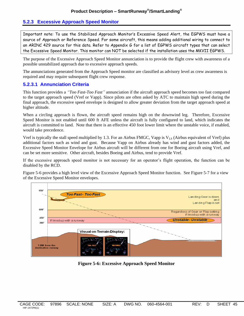
Product Description – SmartRunway®/SmartLanding®
CAGE CODE: 97896 SCALE: NONE SIZE: A DWG NO. 060-4564-001 REV: D SHEET 45 HIF-1472R6(1)
5.2.3 Excessive Approach Speed Monitor
Important note: To use the Stabilized Approach Monitor’s Excessive Speed Alert, the EGPWS must have a
source of Approach or Reference Speed. For some aircraft, this means adding additional wiring to connect to
an ARINC 429 source for this data. Refer to Appendix G for a list of EGPWS aircraft types that can select
the Excessive Speed Monitor. This monitor can NOT be selected if the installation uses the MKVII EGPWS.
The purpose of the Excessive Approach Speed Monitor annunciation is to provide the flight crew with awareness of a
possible unstabilized approach due to excessive approach speeds.
The annunciations generated from the Approach Speed monitor are classified as advisory level as crew awareness is
required and may require subsequent flight crew response.
5.2.3.1 Annunciation Criteria
This function provides a “Too Fast-Too Fast” annunciation if the aircraft approach speed becomes too fast compared
to the target approach speed (Vref or Vapp). Since pilots are often asked by ATC to maintain high speed during the
final approach, the excessive speed envelope is designed to allow greater deviation from the target approach speed at
higher altitude.
When a circling approach is flown, the aircraft speed remains high on the downwind leg. Therefore, Excessive
Speed Monitor is not enabled until 600 ft AFE unless the aircraft is fully configured to land, which indicates the
aircraft is committed to land. Note that there is an effective 450 foot lower limit where the unstable voice, if enabled,
would take precedence.
Vref is typically the stall speed multiplied by 1.3. For an Airbus FMGC, Vapp is VLS (Airbus equivalent of Vref) plus
additional factors such as wind and gust. Because Vapp on Airbus already has wind and gust factors added, the
Excessive Speed Monitor Envelope for Airbus aircraft will be different from one for Boeing aircraft using Vref, and
can be set more sensitive. Other aircraft, besides Boeing and Airbus, tend to provide Vref.
If the excessive approach speed monitor is not necessary for an operator‟s flight operation, the function can be
disabled by the RCD.
Figure 5-6 provides a high level view of the Excessive Approach Speed Monitor function. See Figure 5-7 for a view
of the Excessive Speed Monitor envelopes.
Figure 5-6: Excessive Approach Speed Monitor
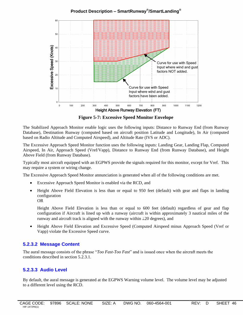
Product Description – SmartRunway®/SmartLanding®
CAGE CODE: 97896 SCALE: NONE SIZE: A DWG NO. 060-4564-001 REV: D SHEET 46 HIF-1472R6(1)
0
10
20
30
40
50
60
0 100 200 300 400 500 600 700 800 900 1000 1100 1200
Height Above Runway Elevation (FT)
Exce
ssiv
e S
pe
ed
(K
no
ts)
Curve for use with Speed
Input where wind and gust
factors NOT added.
Curve for use with Speed
Input where wind and gust
factors have been added.
Figure 5-7: Excessive Speed Monitor Envelope
The Stabilized Approach Monitor enable logic uses the following inputs: Distance to Runway End (from Runway
Database), Destination Runway (computed based on aircraft position Latitude and Longitude), In Air (computed
based on Radio Altitude and Computed Airspeed), and Altitude Rate (IVS or ADC).
The Excessive Approach Speed Monitor function uses the following inputs: Landing Gear, Landing Flap, Computed
Airspeed, In Air, Approach Speed (Vref/Vapp), Distance to Runway End (from Runway Database), and Height
Above Field (from Runway Database).
Typically most aircraft equipped with an EGPWS provide the signals required for this monitor, except for Vref. This
may require a system or wiring change.
The Excessive Approach Speed Monitor annunciation is generated when all of the following conditions are met.
Excessive Approach Speed Monitor is enabled via the RCD, and
Height Above Field Elevation is less than or equal to 950 feet (default) with gear and flaps in landing
configuration
OR
Height Above Field Elevation is less than or equal to 600 feet (default) regardless of gear and flap
configuration if Aircraft is lined up with a runway (aircraft is within approximately 3 nautical miles of the
runway and aircraft track is aligned with the runway within 20 degrees), and
Height Above Field Elevation and Excessive Speed (Computed Airspeed minus Approach Speed (Vref or
Vapp) violate the Excessive Speed curve.
5.2.3.2 Message Content
The aural message consists of the phrase “Too Fast-Too Fast” and is issued once when the aircraft meets the
conditions described in section 5.2.3.1.
5.2.3.3 Audio Level
By default, the aural message is generated at the EGPWS Warning volume level. The volume level may be adjusted
to a different level using the RCD.

Product Description – SmartRunway®/SmartLanding®
CAGE CODE: 97896 SCALE: NONE SIZE: A DWG NO. 060-4564-001 REV: D SHEET 47 HIF-1472R6(1)
5.2.3.4 Visuals
Since this annunciation is considered an advisory, a visual is optional. If configured to do so, the EGPWS presents
the text string “TOO FAST” overlaid on top of the terrain image upon activation of the aural. The text is amber in
color and centered on the display. Figure 5-6 provides an example of the EGPWS generated terrain overlay.
The text will remain on the display until any one of the following conditions exists: configured timer expires (default
is 16 seconds), range on the terrain display is changed, a new voice with associated visual annunciation is issued, a
Terrain/Obstacle caution or warning condition exists, or Height Above Field (AFE) is less than or equal to 300 feet.
The visual annunciation may be enabled or disabled via the RCD.
5.2.4 Unstable Approach Monitor
The purpose of the Unstable Approach Monitor annunciation is to provide the flight crew with awareness of a
possible unstabilized approach.
The annunciations generated from the Unstable Approach monitor are classified as caution level as crew awareness is
required and subsequent flight crew response is required.
5.2.4.1 Annunciation Criteria
This function provides an “Unstable-Unstable” annunciation if the aircraft has not been stabilized by the “450 ft
Gate”. Figure 5-8 provides a high level view of the Unstable Approach function. The figure includes the possible
triggers that can lead to activation of the unstable annunciation.
Figure 5-8: Stabilized Approach Monitor
The Stabilized Approach Monitor enable logic uses the following inputs: Distance to Runway End (from Runway
Database), Destination Runway (computed based on aircraft position Latitude and Longitude), In Air (computed
based on Radio Altitude and Computed Airspeed), and Altitude Rate (IVS or ADC).
The Unstable Approach Monitor function uses the following inputs: Landing Gear, Landing Flap, Altitude Rate (IVS
or ADC), Distance to Runway End (from Runway Database), and Height Above Field (from Runway Database).
Typically most aircraft equipped with an EGPWS provide the signals required for this monitor with no additional
system or wiring changes required.

Product Description – SmartRunway®/SmartLanding®
CAGE CODE: 97896 SCALE: NONE SIZE: A DWG NO. 060-4564-001 REV: D SHEET 48 HIF-1472R6(1)
The Unstable Approach Monitor annunciation is generated when all of the following conditions are met.
Height Above Field Elevation is less than or equal 450 feet (default) and greater than 300 feet (default), and
One of the Approach Monitor triggers has been annunciated (Landing Flap Monitor, Excessive Approach
Angle Monitor, or Excessive Approach Speed Monitor).
As shown above, the Unstable Approach annunciation will not be provided until after one of the other Stabilized
Approach Monitor annunciations has been issued.
5.2.4.2 Message Content
The aural message consists of the phrase “Unstable-Unstable” and is issued once if the aircraft has not been
stabilized by 450 feet AFE as described in section 5.2.4.1
5.2.4.3 Audio Level
By default, the aural message is generated at the EGPWS Warning volume level. The volume level may be adjusted
to a different level using the RCD.
5.2.4.4 Visuals
This annunciation is considered a caution, so a visual indication is required when an aural annunciation is activated.
The function is configured, by default, to provide illumination of an existing EGPWS cockpit lamp and present the
text string “UNSTABLE” overlaid on top of the terrain image upon activation of the aural. Configuration options
allow the function to drive either the lamp or visual annunciation on the Terrain Display, both, or neither. If the
cockpit lamp option is selected the caution lamp is illuminated upon activation of the annunciation and stays active as
long as the unstable condition exists. Figure 5-9 shows an example of a typical lamp interface. If the terrain display
option is selected, the text is amber in color and centered on the display. Several of the figures in the previous
Approach Monitor sections have examples of the EGPWS generated terrain overlay for „Unstable‟.
The text on the terrain display will remain on the display until any one of the following conditions exists: configured
timer expires (default is 16 seconds), range on the terrain display is changed, a new voice with associated visual
annunciation is issued, a Terrain/Obstacle caution or warning condition exists, or Height Above Field (AFE) is less
than or equal to 300 feet.
The visual annunciations may be enabled or disabled via the RCD.
G/S Cancel Discrete
Input
GPWS Caution Alert
Discrete Output
EGPWS
PULL UP
GND PROX
G/S INHIBIT UNSTABLE
Figure 5-9: Lamp Visual (Activated for Unstable Approach Annunciation)

Product Description – SmartRunway®/SmartLanding®
CAGE CODE: 97896 SCALE: NONE SIZE: A DWG NO. 060-4564-001 REV: D SHEET 49 HIF-1472R6(1)
5.3 Assumptions, Limitations and Constraints
Honeywell‟s Stabilized Approach Monitor provides both advisory and caution annunciations. Advisories are for
conditions that require flight crew awareness and may require subsequent flight crew response. Cautions are for
conditions that require immediate flight crew awareness and subsequent flight crew response.
Appropriate flight crew action is as follows:
Annunciation Expected Crew Response Alert Level
Flaps (pause) Flaps
(in air at 950 ft AFE)
Flaps-Flaps
(in air at 600 ft AFE)
Verify flap position and select flap as required. Advisory
Too High-Too High
Verify vertical position, apply corrections as required. Advisory
Too Fast-Too Fast Verify airspeed and adjust as necessary. Advisory
Unstable-Unstable
(Flap 450–300ft AFE)
(Too High 450–300ft AFE)
(Too Fast 450–300ft AFE)
Verify whether approach parameters are as expected/briefed
and take appropriate action as necessary.
Caution
Information contained herein or provided by a Stabilized Approach Monitor annunciation does not supersede any
operator Standard Operating Procedure (SOP).
Runway location data may have errors inherent in the source of such data. Such errors can delay an alert, or may
cause unwanted alerts.
The Stabilized Approach Monitors may become Not Available at any time due to loss of accuracy of GPS
signals.
Other EGPWS aural alerts may preempt Stabilized Approach Monitor annunciations. Stabilized Approach
Monitor annunciations may be issued during ATC radio communications, flight crew / cockpit communications,
or during other aural messages provided in the cockpit by other aircraft systems.

Product Description – SmartRunway®/SmartLanding®
CAGE CODE: 97896 SCALE: NONE SIZE: A DWG NO. 060-4564-001 REV: D SHEET 50 HIF-1472R6(1)
6. Altimeter Monitor
The Altimeter Monitor provides the flight crew with two advisories that inform of improper altimeter setting. One
monitor detects altimeter setting errors while the aircraft is below the transition altitude and the second detects if the
altimeter has not be set to the standard altitude when the aircraft climbs above the transition altitude.
6.1 Altimeter Monitor Availability and Options
The Altimeter Monitor is operationally available anytime the EGPWS is powered and the following conditions are
met:
For MKV/MKVII EGPWS: Software Version 230-230 or later with a serial number EGPWC unit that has
been enabled to use the functions described in this document (this is referred to as the „Enable Key being
Set‟), or EGPWS Software Version 965-1690-054 or later with the Enable Key Set, or 965-1676-004 or later
with the Enable Key Set. For MKV-A EGPWS: software version 01.01 or later and Enable Key Set, or
software version 51.01 or later and Enable Key Set. Refer to section 9.1 for more information on the Enable
Key.
Terrain Database 435 or later.
The Altimeter Monitor options have been loaded via an RCD into the EGPWC.
The selected destination runway for the Runway Data (loaded as part of the Terrain Database) contains a
valid Transition Altitude, or the height above the selected runway is less than 1,500 feet.
For the below transition altitude monitor the aircraft is not operating under QFE conditions. The EGPWS is
not configured for QFE operations, the selected Barometric Reference (if available to the EGPWS) is not set
to QFE, and the selected destination runway is not indicated as a QFE runway.
Note 1: Some AIRBUS aircraft provide the EGPWS with a Barometric Altitude Reference selection. If
this selection is set to QFE the Altimeter Monitor will be automatically inhibited.
Note 2: Airport runways in Russia and China that are designated for QFE operation are noted in the
Terrain/Runway database. The Altimeter Monitor will be automatically inhibited at these airport
runways.
For MKV-A EGPWS, and MKV/MKVII EGPWS Software Version 965-0976-236-236, 965-1676-006, and
965-1690-057 and later:
Some customers operating at QFE airports fly the approaches with their altimeters set to QNH and want
Altimeter Monitor to be active and available. An option was added to override the QFE disabling of
Altimeter Monitor function when the EGPWS detects the approach is to a QFE runway. This option will
not override QFE disabling due to Barometric Altitude Reference being set to QFE or selection of QFE
input.
The required input signals are valid and reasonable. Required inputs signals include corrected pressure
altitude, uncorrected pressure altitude, and static air temperature from the ADC, GPS Altitude, accuracy, and
integrity data from the GPS receiver, radio altitude, and roll angle.
Altimeter Monitor Availability is integrated into the existing EGPWS fault monitoring and Self-Test functions.
For software versions prior to 965-0976-236-236, 965-1676-006, and 965-1690-057, the operational status is
not provided by the existing GPWS and TAD status output.
For MKV-A EGPWS, and MKV/MKVII EGPWS Software versions 965-0976-236-236, 965-1676-006, and
965-1690-057 and later:
The EGPWS also provides a RAAS Monitor discrete output as well as ARINC 429 RAAS INOP and
RAAS Not Available outputs.

Product Description – SmartRunway®/SmartLanding®
CAGE CODE: 97896 SCALE: NONE SIZE: A DWG NO. 060-4564-001 REV: D SHEET 51 HIF-1472R6(1)
The RAAS Monitor discrete will be active if any RCD enabled monitoring function (RAAS, Long
Landing, Stabilized Approach, Altimeter, Takeoff Flap) becomes inoperative or not available. This
discrete may be used to drive a dedicated RAAS INOP / Not Available lamp. Note to maintain backward
compatibility that the system can be configured via the RCD to activate the GPWS INOP for RAAS INOP
conditions.
The ARINC 429 RAAS INOP will be active if any RCD enabled monitor function becomes INOP.
Similarly the ARINC 429 RAAS Not Available will become active if any RCD enabled monitor function
is not available. If supported by Crew Alerting System (CAS) these labels may be used to drive dedicated
RAAS INOP or RAAS Not Available CAS messages.
Option to include QFE approach in the Not Available logic. If the option is selected and the EGPWS
detects that the approach is to a QFE runway then the Altimeter Monitor function will be set to Not
Available.
Consistent with approved EGPWS Self-Test design, the status of the Altimeter Monitor function will be indicated
on-ground during a level 1 Self-Test. Refer to Appendix D for a list of Self-Test maintenance messages.
For software versions prior to 965-0976-236-236, 965-1676-006, and 965-1690-057:
The option for a cockpit selection to inhibit the Altimeter Monitor annunciations was not available. Due to the
nature of this message and the inputs which are monitored, it was determined that an option to inhibit these
annunciations was not required.
For MKV-A EGPWS and MKV/MKVII Software versions 965-0976-236-236, 965-1676-006, and 965-1690-057
and later:
The option to inhibit the Altimeter Monitor annunciations was added. The inhibit option allows for inhibiting via
the RAAS inhibit or Stabilized Approach Monitor inhibit cockpit switch.
All Altimeter Monitor Options are global. In other words, all aircraft types defined in the RCD function the same
with respect to the Altimeter Monitor.
Table 6-1: Altimeter Monitior Options
DESCRIPTION Global
Option
A/C
Type
Specific
Option
SELECTIONS REF
SECTION
Voice Gender X MALE,FEMALE 3.1
Below Transition Altitude Monitor X OFF, ON 6.2.1
Above Transition Altitude Monitor X OFF, ON 6.2.2
Enable Visual Messages on
Terrain Display X NONE, ALL, NON-ROUTINE ONLY,
CAUTIONS ONLY
(Altimeter Monitor is not a caution)
9.3
Altimeter Monitor Enable/Inhibit X NONE, EQUAL TO RAAS INH
DISCRETE, EQUAL TO Stabilized
Approach Monitor INHIBIT
DISCRETE
6.1
QFE Runway Override X OFF, ON 6.2.1
Destination runway is QFE then
Altimeter Monitor Not Available
output is set true
X OFF, ON 6.1

Product Description – SmartRunway®/SmartLanding®
CAGE CODE: 97896 SCALE: NONE SIZE: A DWG NO. 060-4564-001 REV: D SHEET 52 HIF-1472R6(1)
6.2 Altimeter Monitor Sub-Monitors
6.2.1 Below Transition Altitude Monitor
The purpose of this monitor is to provide the flight crew with awareness of improper corrected altitude setting while
operating below the transition altitude.
The annunciation generated from this monitor is classified as an advisory level as crew awareness may be required
and crew response is not necessarily imminent.
6.2.1.1 Annunciation Criteria
The EGPWS compares Corrected Altitude from the Air Data Computer (ADC) with the Global Positioning System
(GPS) Altitude from the GPS receiver. If the difference between the two altitudes exceeds a computed threshold
value an Altimeter Setting aural message and an optional visual annunciation are generated. Note that the EGPWS
does not perform a cross check of both Air Data inputs because if the pilot‟s side data and co-pilot‟s side data are
different, a function external to the EGPWS provides an indication to the crew. Therefore the EGPWS compares
Corrected Altitude with GPS Altitude from the pilot‟s side data only. The advisory threshold is dynamically
computed based on estimated errors due to non-standard atmospheric conditions, current GPS accuracy, and Air Data
system errors. Since the threshold is dynamic, the size of the error that can be detected varies with the current
aircraft state and sensor conditions. The figure below shows the size of errors that can be detected for typical
conditions as function of the aircraft height above field for different ISA temperature deviations.
Detectable Error for Various Temp Deviations
0
2000
4000
6000
8000
10000
12000
14000
16000
18000
20000
0 500 1000 1500 2000
Size of Detected Error (Ft)
Heig
ht
Ab
ove F
ield
(F
t)
ISA
ISA +/- 10
ISA +/- 20
ISA +/-30
Figure 6-1: Altimeter Monitor Detectable Error
The Altimeter Monitor includes a cross check on the GPS Altitude to prevent nuisance advisories caused by
erroneous GPS Altitude values. The cross-check compares GPS Altitude with aircraft altitude computed using
radio altitude and the terrain elevation from the terrain database. The difference between these altitudes is
compared against a dynamically computed threshold based on the current GPS accuracy, radio altitude accuracy,
and the estimated terrain database accuracy. If the cross-check fails, then the Below Transition Altitude Monitor
is disabled to prevent nuisance annunciations caused by erroneous GPS Altitude values.

Product Description – SmartRunway®/SmartLanding®
CAGE CODE: 97896 SCALE: NONE SIZE: A DWG NO. 060-4564-001 REV: D SHEET 53 HIF-1472R6(1)
The Altimeter Monitor uses the following inputs: GPS data (including Altitude, Vertical Figure of Merit, Non-
Isolatable Satellite Failure (NISF), Horizontal Integrity Limit, Number of Satellites, and Operating Mode), and
ADC data (Corrected Barometric Altitude, Pressure Altitude, and Static Air Temperature).
Typically most aircraft equipped with an EGPWS provide the signals required for this monitor with no additional
system or wiring changes required.
The Below Transition Altitude Monitor annunciation is generated when the following conditions are met:
GPS Altitude and Vertical Figure of Merit (VFOM) are valid and have passed internal reasonableness
checks
GPS is not in altitude aiding mode, the number of satellites tracked is 5 or greater, a non-isolatable
satellite failure (NISF) does not exist, and GPS Horizontal Integrity Limit (HIL) is valid
Corrected Barometric Altitude and Static Air Temperature are valid
EGPWS Runway Database is valid
Aircraft Altitude is less than the Transition Altitude for more than 30 seconds OR Height Above Field is
less than 1500 feet. The transition altitude is obtained from the EGPWS runway database for the
destination runway.
Aircraft is within 20 nautical miles of the EGPWS Selected destination runway
Height above field is less than 5000 feet
For software versions prior to 965-0976-236-236, 965-1676-006, and 965-1690-057:
Airport is not indicated as QFE, altimeter setting is not QFE, and QFE program pin is not selected
For MKV-A EGPWS, and MKV/MKVII EGPWS Software versions 965-0976-236-236, 965-1676-006,
and 965-1690-057 and later:
Airport is not indicated as QFE or a QFE override option is selected, altimeter setting is not QFE, and
QFE program pin is not selected
Note: The RCD QFE Override option should only be selected if aircraft is certified to perform
non-QFE approaches at QFE destinations.
Radio Height is greater than 600 feet
The filtered difference between Corrected Altitude and GPS Altitude exceeds a threshold computed
based on the current estimated altimetry system errors
6.2.1.2 Message Content
The aural message consists of the phrase “Altimeter Setting”. This advisory is issued once when the altimeter error is
first detected and will repeat once, 8 seconds later. After two voice messages, no additional messages will be
generated.
The advisory will be re-armed if the enable logic goes false and then true or after a change in the altimeter setting is
detected by the EGPWS.
6.2.1.3 Audio Level
By default, the aural message is generated at the EGPWS Warning volume, but the audio level may be adjusted to a
different level using the RCD.
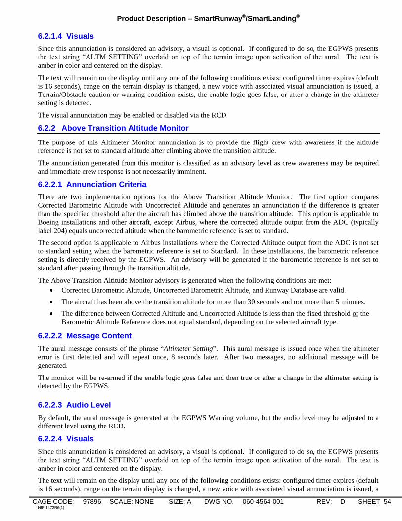
Product Description – SmartRunway®/SmartLanding®
CAGE CODE: 97896 SCALE: NONE SIZE: A DWG NO. 060-4564-001 REV: D SHEET 54 HIF-1472R6(1)
6.2.1.4 Visuals
Since this annunciation is considered an advisory, a visual is optional. If configured to do so, the EGPWS presents
the text string “ALTM SETTING” overlaid on top of the terrain image upon activation of the aural. The text is
amber in color and centered on the display.
The text will remain on the display until any one of the following conditions exists: configured timer expires (default
is 16 seconds), range on the terrain display is changed, a new voice with associated visual annunciation is issued, a
Terrain/Obstacle caution or warning condition exists, the enable logic goes false, or after a change in the altimeter
setting is detected.
The visual annunciation may be enabled or disabled via the RCD.
6.2.2 Above Transition Altitude Monitor
The purpose of this Altimeter Monitor annunciation is to provide the flight crew with awareness if the altitude
reference is not set to standard altitude after climbing above the transition altitude.
The annunciation generated from this monitor is classified as an advisory level as crew awareness may be required
and immediate crew response is not necessarily imminent.
6.2.2.1 Annunciation Criteria
There are two implementation options for the Above Transition Altitude Monitor. The first option compares
Corrected Barometric Altitude with Uncorrected Altitude and generates an annunciation if the difference is greater
than the specified threshold after the aircraft has climbed above the transition altitude. This option is applicable to
Boeing installations and other aircraft, except Airbus, where the corrected altitude output from the ADC (typically
label 204) equals uncorrected altitude when the barometric reference is set to standard.
The second option is applicable to Airbus installations where the Corrected Altitude output from the ADC is not set
to standard setting when the barometric reference is set to Standard. In these installations, the barometric reference
setting is directly received by the EGPWS. An advisory will be generated if the barometric reference is not set to
standard after passing through the transition altitude.
The Above Transition Altitude Monitor advisory is generated when the following conditions are met:
Corrected Barometric Altitude, Uncorrected Barometric Altitude, and Runway Database are valid.
The aircraft has been above the transition altitude for more than 30 seconds and not more than 5 minutes.
The difference between Corrected Altitude and Uncorrected Altitude is less than the fixed threshold or the
Barometric Altitude Reference does not equal standard, depending on the selected aircraft type.
6.2.2.2 Message Content
The aural message consists of the phrase “Altimeter Setting”. This aural message is issued once when the altimeter
error is first detected and will repeat once, 8 seconds later. After two messages, no additional message will be
generated.
The monitor will be re-armed if the enable logic goes false and then true or after a change in the altimeter setting is
detected by the EGPWS. 24
6.2.2.3 Audio Level
By default, the aural message is generated at the EGPWS Warning volume, but the audio level may be adjusted to a
different level using the RCD.
6.2.2.4 Visuals
Since this annunciation is considered an advisory, a visual is optional. If configured to do so, the EGPWS presents
the text string “ALTM SETTING” overlaid on top of the terrain image upon activation of the aural. The text is
amber in color and centered on the display.
The text will remain on the display until any one of the following conditions exists: configured timer expires (default
is 16 seconds), range on the terrain display is changed, a new voice with associated visual annunciation is issued, a

Product Description – SmartRunway®/SmartLanding®
CAGE CODE: 97896 SCALE: NONE SIZE: A DWG NO. 060-4564-001 REV: D SHEET 55 HIF-1472R6(1)
Terrain/Obstacle caution or warning condition exists, the enable logic goes false, or after a change in the altimeter
setting is detected.
The visual annunciation may be enabled or disabled via the RCD.
6.3 Assumptions, Limitations, and Constraints
Honeywell‟s Altimeter Monitor provides advisory annunciations. It is classified this way because awareness
may be required and crew response is not necessarily imminent.
Appropriate flight crew action is as follows:
Alert Expected Crew Response Alert Level
Altimeter Setting (above transition
altitude)
Check altimeter setting, procedure
altitude, ATC assistance as necessary.
Advisory
Altimeter Setting (below transition
altitude)
Check altimeter setting, procedure
altitude, ATC assistance as necessary
and climb if inadequate terrain
separation is suspected in IMC. Check
static ports & heaters.
Advisory
The Altimeter Monitor is designed to detect errors caused by an incorrectly set altimeter. Other errors such
as plugged static port or single or cumulative errors in the air data or other systems may also result in an
advisory.
The Altimeter Monitor is not designed to detect differences between corrected altitude and the geometric
altitude of the aircraft caused by temperature variations or other deviations from the ISA model. Standard
procedures and limitations for operations in non-standard ISA conditions, including cold temperature, remain
applicable.
Information contained herein or provided by the Altimeter Monitor advisory does not supersede any operator
Standard Operating Procedure (SOP).
Runway selection logic and transition altitude data may have errors inherent in the source of such data. Such
errors can delay or prevent an advisory or may cause unwanted advisories.
Other EGPWS aural alerts and warnings may preempt or delay the Altimeter Monitor advisory. Altimeter
Monitor advisories may be issued during ATC radio communications, flight crew / cockpit communications,
or during other aural messages provided in the cockpit by other aircraft systems.
7. Takeoff Flap Configuration Monitor
Important note: To use the Takeoff Flap Configuration Monitor, the EGPWS installed on the aircraft must
already be connected to a source of flap position. Refer to Appendix G for a list of EGPWS aircraft types
that support such a connection. In addition, as also described in Appendix G, some aircraft types may require
that the Reactive Windshear Feature of the EGPWS be activated.
The Takeoff Flap Configuration Monitor is intended to inform the flight crew of improper flap setting for takeoff.
With the benefit of the EGPWS Runway Database, alignment to the runway is detected allowing the annunciation to
be provided well before thrust levers are advanced for takeoff.

Product Description – SmartRunway®/SmartLanding®
CAGE CODE: 97896 SCALE: NONE SIZE: A DWG NO. 060-4564-001 REV: D SHEET 56 HIF-1472R6(1)
7.1 Takeoff Flap Configuration Monitor Availability and Options
7.1.1 Takeoff Flap Configuration Monitor Operational Availability
Takeoff Flaps is operationally available anytime the EGPWS is powered and the following conditions are met:
For MKV and MKVII EGPWS: Software Version 230-230 or later with a serial number EGPWC unit that
has been enabled to use the functions described in this document (this is referred to as the „Enable Key being
Set‟), or EGPWS Software Version 965-1690-054 or later with the Enable Key Set, or 965-1676-004 or later
with the Enable Key Set. For MKV-A EGPWS: software version 01.01 or later and Enable Key Set, or
software version 51.01 or later and Enable Key Set. Refer to section 9.1 for more information on the Enable
Key.
Terrain Database 454 or later. Note that a S/W mod may be required in order to use databases 456 and later – refer to
section 4.1.1 for more information.
The Takeoff Flaps options have been loaded via an RCD into an EGPWC.
The current airport is a RAAS-validated airport in the Runway Database (loaded as part of the Terrain
Database)
Takeoff Flaps is functional (e.g. all external signals are available and not faulted, GPS position accuracy
meets minimum Takeoff Flaps requirements, and there are no internal EGPWC faults).
Takeoff Flaps Operational Availability is integrated into the existing EGPWS fault monitoring and Self-Test
functions. The GPWS INOP Lamp will also reflect the status of the Takeoff Flaps function. An Aircraft-Type
option is available to inhibit the Takeoff Flap Configuration Monitor status from driving the GPWS INOP Lamp
should this be required for a given design. Consistent with approved EGPWS Self-Test design, the loss of Takeoff
Flaps functions will be indicated on-ground during a level 1 Self-Test. Refer to Appendix E for a list of Self-Test
maintenance messages.
7.1.2 EGPWS Runway Database
Current EGPWS databases contain airport and runway information. However, to ensure optimal Takeoff Flap
Configuration Monitor performance, the accuracy of this data is re-verified and validated before the function can use
the data. EGPWS Terrain database 454 and later contains additional airport and runway information that the monitor
uses to determine if it can perform its intended function. Note that if the runway has been validated for RAAS it is
also valid for the Takeoff Flap Configuration Monitor.
7.1.3 Signals Required
7.1.3.1 GPS Signals Required, Accuracy and Availability
Takeoff Flaps requires a high level of GPS position accuracy to function. GPS receivers used to provide position
information must have a position resolution of 50 feet or better to meet this requirement. In addition to the basic set
of GPS position data, Takeoff Flaps requires GPS Fine Latitude (ARINC 429 Label 120) and GPS Fine Longitude
(ARINC 429 Label 121). Most ARINC 743/743A GPS systems provide these signals. The internal GPS receivers
used with the EGPWS provide the needed resolution.
The Takeoff Flap Configuration Monitor does not require WAAS or Differential GPS (DGPS). However, either or
both could enhance position accuracy of standard GPS data. The function monitors GPS accuracy and will
automatically become Not Available if the accuracy degrades below acceptable limits. Factors which could degrade
GPS accuracy include intentional accuracy degradation (Selective Availability activated), signal multipath,
ionospheric and tropospheric delays, satellite geometry and shading, and system errors such as clock inaccuracies,
etc.
7.1.3.2 Flap Position
Flap position is required for this function, so the EGPWS installed on the aircraft must already be connected to a
source of flap position. This data can come from a flap handle or actual flap position and must be scaled in degrees.

Product Description – SmartRunway®/SmartLanding®
CAGE CODE: 97896 SCALE: NONE SIZE: A DWG NO. 060-4564-001 REV: D SHEET 57 HIF-1472R6(1)
The discrete that indicates Landing Flaps/Not Landing Flaps is not appropriate for this monitor. Refer to Appendix G
for a list of EGPWS aircraft types that support a flap position input.
7.1.4 Takeoff Flap Configuration Monitor Options Summary
The option for a separate cockpit selection to inhibit the Takeoff Flap Configuration Monitor annunciations has not
been added to the aircraft configuration or EGPWS logic. Instead, the existing RAAS inhibit cockpit selection can
be used to inhibit both RAAS and Takeoff Flap Configuration Monitor annunciations.
Global Options are applicable for all Takeoff Flap Configuration Monitor features and will be the same for all
aircraft types programmed in the RCD. For example, aural annunciations may be specified to be a Male or Female
voice. If the Male voice is selected, all annunciations will use the Male voice. If one alert is set to Male, another
cannot be set to Female.
Aircraft-Type Specific options can be selected differently between various aircraft types specified in the RCD. The
following table indicates which options are global and which are aircraft specific.
DESCRIPTION Global
Option
A/C
Type
Specific
Option
SELECTIONS REF SECTION
Voice Gender X FEMALE, MALE 3.1
Takeoff Flap Handle Minimum
Setting
X 0 to 50 degrees (see note 1) 7.2.1
Takeoff Flap Handle Maximum
Setting
X 0 to 50 degrees (see note 1) 7.2.1
Enable Visual Messages on
Terrain Display X NONE, ALL, NON-ROUTINE
ONLY, CAUTIONS ONLY
9.3
Note 1: In addition to physical Flap Handle settings, indicate what range (if any) the Flap Position input to the
EGPWS is at those settings. For example, if an ARINC 429 Flap Angle input is the source of Flap Position to the
EGPWS, what value will it indicate for the corresponding Handle positions: For example, a handle setting of 5 may
result in a flap angle range of 3 to 7 degrees.
7.2 On Runway – Takeoff Flap Configuration Monitor
The purpose of the Takeoff Flap Configuration Monitor is to provide the flight crew with awareness of improper flap
setting when the aircraft is lined-up on a runway in advance of takeoff.
The annunciation generated from this monitor is classified as a caution since immediate crew awareness is required
and subsequent crew action may be required.
7.2.1 Annunciation Criteria
The Takeoff Flap Configuration Monitor annunciation is generated when the following conditions are met:
Flap handle not within the valid takeoff flap setting, and
Aircraft enters a runway, and
Aircraft heading is within 20 degrees of the runway heading.
7.2.2 Message Content
The aural message consists of the phrase “Flaps Flaps” (refer to Figure 7-1). This aural message is annunciated once
each time the aircraft enters, and is aligned with, a runway, if the flap setting is incorrect. No further aural messages
are provided unless the flap handle is adjusted and, after 5 seconds of settling time, the flaps are still not set within
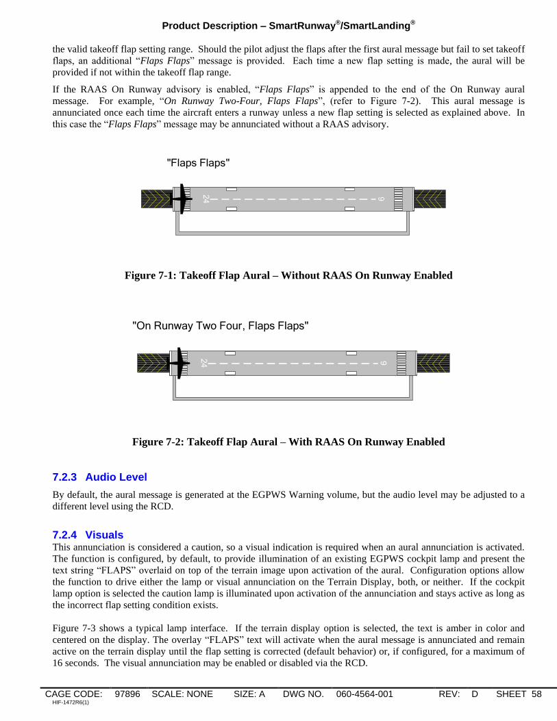
Product Description – SmartRunway®/SmartLanding®
CAGE CODE: 97896 SCALE: NONE SIZE: A DWG NO. 060-4564-001 REV: D SHEET 58 HIF-1472R6(1)
the valid takeoff flap setting range. Should the pilot adjust the flaps after the first aural message but fail to set takeoff
flaps, an additional “Flaps Flaps” message is provided. Each time a new flap setting is made, the aural will be
provided if not within the takeoff flap range.
If the RAAS On Runway advisory is enabled, “Flaps Flaps” is appended to the end of the On Runway aural
message. For example, “On Runway Two-Four, Flaps Flaps”, (refer to Figure 7-2). This aural message is
annunciated once each time the aircraft enters a runway unless a new flap setting is selected as explained above. In
this case the “Flaps Flaps” message may be annunciated without a RAAS advisory.
24 6
"Flaps Flaps"
Figure 7-1: Takeoff Flap Aural – Without RAAS On Runway Enabled
24 6
"On Runway Two Four, Flaps Flaps"
Figure 7-2: Takeoff Flap Aural – With RAAS On Runway Enabled
7.2.3 Audio Level
By default, the aural message is generated at the EGPWS Warning volume, but the audio level may be adjusted to a
different level using the RCD.
7.2.4 Visuals This annunciation is considered a caution, so a visual indication is required when an aural annunciation is activated.
The function is configured, by default, to provide illumination of an existing EGPWS cockpit lamp and present the
text string “FLAPS” overlaid on top of the terrain image upon activation of the aural. Configuration options allow
the function to drive either the lamp or visual annunciation on the Terrain Display, both, or neither. If the cockpit
lamp option is selected the caution lamp is illuminated upon activation of the annunciation and stays active as long as
the incorrect flap setting condition exists.
Figure 7-3 shows a typical lamp interface. If the terrain display option is selected, the text is amber in color and
centered on the display. The overlay “FLAPS” text will activate when the aural message is annunciated and remain
active on the terrain display until the flap setting is corrected (default behavior) or, if configured, for a maximum of
16 seconds. The visual annunciation may be enabled or disabled via the RCD.

Product Description – SmartRunway®/SmartLanding®
CAGE CODE: 97896 SCALE: NONE SIZE: A DWG NO. 060-4564-001 REV: D SHEET 59 HIF-1472R6(1)
G/S Cancel Discrete Input
GPWS Caution Alert
Discrete Output
EGPWS
PULL UP
GND PROX
G/S INHIBIT
INCORRECT
TAKEOFF FLAPS –
CAUTION
Figure 7-3: Incorrect Takeoff Lamp Visual
7.3 Assumptions, Limitations and Constraints
Honeywell‟s Takeoff Flap Configuration Monitor provides a caution alert. It is classified this way because
immediate crew awareness is required.
Appropriate flight crew action is as follows:
Alert Expected Crew Response Alert Level
Flaps – Flaps on runway VERIFY Flap Setting and
Configure as Necessary for
Takeoff.
Caution
Information contained herein or provided by a Takeoff Flap Configuration Monitor caution alert does not
supersede any operator Standard Operating Procedure (SOP).
Runway location data may have errors inherent in the source of such data. Such errors can delay an alert, or may
cause unwanted alerts.
The Takeoff Flap Configuration Monitor may become Not Available at any time due to loss of accuracy of GPS
signals.
Other EGPWS aural alerts may preempt Takeoff Flap alert. Takeoff Flap alerts may be issued during ATC radio
communications, flight crew / cockpit communications, or during other aural messages provided in the cockpit
by other aircraft systems.

Product Description – SmartRunway®/SmartLanding®
CAGE CODE: 97896 SCALE: NONE SIZE: A DWG NO. 060-4564-001 REV: D SHEET 60 HIF-1472R6(1)
8. Long Landing Monitor
The Long Landing Monitor function offers pilot increased runway awareness and complements the RAAS Distance
Remaining callouts. The function advises the crew of their position during a landing when the aircraft has not
touched down in a nominal amount of distance.
In addition to providing the Long Landing aural during a long landing event, a set of airborne only distance
remaining callouts can also be selected.
The annunciations generated from this monitor are classified as caution level as immediate crew awareness and
subsequent crew response is possibly required.
8.1 Long Landing Monitor Availability and Options
The operational availability criteria and operational status for RAAS In-Air callouts, as described in section
4.1.1, are applicable to the Long Landing Monitor.
The option for a separate cockpit selection to inhibit the Long Landing Monitor annunciations has not been added to
the aircraft configuration or EGPWS logic. Instead, the existing RAAS inhibit cockpit selection can be used to
inhibit both RAAS and Long Landing Monitor annunciations.
Global Options are applicable for all Long Landing Monitor features and will be the same for all aircraft types
programmed in the RCD. For example, aural annunciations may be specified to be a Male or Female voice. If the
Male voice is selected, all annunciations will use the Male voice. If one alert is set to Male, another cannot be set to
Female.
Aircraft-Type Specific options can be selected differently between various aircraft types specified in the RCD. The
following table indicates which options are global and which are aircraft specific.
DESCRIPTION Global
Option
A/C
Type
Specific
Option
SELECTIONS REF SECTION
Long Landing Monitor X OFF, ON 8.2
Voice Gender X MALE, FEMALE 3.1
Enable/Inhibit Discrete X NONE, INHIBIT, ENABLE See above
Long Landing Voice X LONG LANDING, DEEP LANDING 8.2.2
Long Landing Reference Point X CALLOUT TRIGGER POINT
MEASURED FROM APPROACH
END OF RUNWAY
CALLOUT TRIGGER POINT
MEASURED FROM DEPARTURE
END OF THE RUNWAY
8.2.2
Long Landing Distance X 1 TO 10,000 FT (3000 METERS) 8.2.2
Long Landing Percentage X PERCENTAGE OF RUNWAY REMAINING TO TRIGGER CALL
8.2.2
Long Landing Distance Remaining
X ON, OFF, INCLUDE UNITS 8.2.2

Product Description – SmartRunway®/SmartLanding®
CAGE CODE: 97896 SCALE: NONE SIZE: A DWG NO. 060-4564-001 REV: D SHEET 61 HIF-1472R6(1)
DESCRIPTION Global
Option
A/C
Type
Specific
Option
SELECTIONS REF SECTION
Long Landing Distance
Remaining Calls Datum X APPROACH END
DEPARTURE END
8.2.2
Long Landing Distance
Remaining X 1 TO 10,000 FT (3000 METERS) 8.2.2
Long Landing Distance Remaining Percentage
X PERCENTAGE OF RUNWAY REMAINING TO TRIGGER CALLOUTS
8.2.2
Enable Visual Messages on Terrain Display
X NONE, ALL, NON-ROUTINE ONLY, CAUTIONS ONLY
9.3
8.2 Long Landing Monitor
The Long Landing Monitor adds two new distance remaining annunciations to enhance crew awareness of aircraft
along-track position relative to the runway end. One provides annunciations if the aircraft has not touched down
before a configurable threshold and the second provides airborne only aural annunciations of current distance from
aircraft to the runway end.
Figure 10-1: Long Landing Aural with Subsequent Distance Remaining Calls
The Long Landing Monitor uses GPS position data and the Honeywell EGPWS Runway Database to provide aural
and visual annunciations that supplement flight crew awareness of aircraft position in relation to the runway.
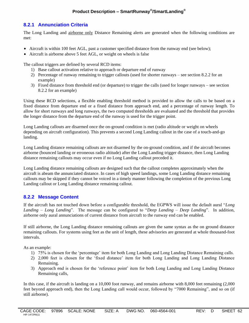
Product Description – SmartRunway®/SmartLanding®
CAGE CODE: 97896 SCALE: NONE SIZE: A DWG NO. 060-4564-001 REV: D SHEET 62 HIF-1472R6(1)
8.2.1 Annunciation Criteria
The Long Landing and airborne only Distance Remaining alerts are generated when the following conditions are
met:
Aircraft is within 100 feet AGL, past a customer specified distance from the runway end (see below);
Aircraft is airborne above 5 feet AGL, or weight on wheels is false
The callout triggers are defined by several RCD items:
1) Base callout activation relative to approach or departure end of runway
2) Percentage of runway remaining to trigger callouts (used for shorter runways – see section 8.2.2 for an
example)
3) Fixed distance from threshold end (or departure) to trigger the calls (used for longer runways – see section
8.2.2 for an example)
Using these RCD selections, a flexible enabling threshold method is provided to allow the calls to be based on a
fixed distance from departure end or a fixed distance from approach end, and a percentage of runway length. To
allow for short runways and long runways, the two computed thresholds are evaluated and the threshold that provides
the longer distance from the departure end of the runway is used for the trigger point.
Long Landing callouts are disarmed once the on-ground condition is met (radio altitude or weight on wheels
depending on aircraft configuration). This prevents a second Long Landing callout in the case of a touch-and-go
landing.
Long Landing distance remaining callouts are not disarmed by the on-ground condition, and if the aircraft becomes
airborne (bounced landing or erroneous radio altitude) after the Long Landing trigger distance, then Long Landing
distance remaining callouts may occur even if no Long Landing callout preceded it.
Long Landing distance remaining callouts are designed such that the callout completes approximately when the
aircraft is abeam the annunciated distance. In cases of high speed landings, some Long Landing distance remaining
callouts may be skipped if they cannot be voiced in a timely manner following the completion of the previous Long
Landing callout or Long Landing distance remaining callout.
8.2.2 Message Content
If the aircraft has not touched down before a configurable threshold, the EGPWS will issue the default aural “Long
Landing – Long Landing”. The message can be configured to “Deep Landing – Deep Landing”. In addition,
airborne only aural annunciations of current distance from aircraft to the runway end can be enabled.
If still airborne, the Long Landing distance remaining callouts are given the same syntax as the on ground distance
remaining callouts. For systems using feet as the unit of length, these advisories are generated at whole thousand-foot
intervals.
As an example:
1) 75% is chosen for the „percentage‟ item for both Long Landing and Long Landing Distance Remaining calls.
2) 2,000 feet is chosen for the „fixed distance‟ item for both Long Landing and Long Landing Distance
Remaining.
3) Approach end is chosen for the „reference point‟ item for both Long Landing and Long Landing Distance
Remaining calls,
In this case, if the aircraft is landing on a 10,000 foot runway, and remains airborne with 8,000 feet remaining (2,000
feet beyond approach end), then the Long Landing call would occur, followed by “7000 Remaining”, and so on (if
still airborne).
Product Description – SmartRunway®/SmartLanding®
CAGE CODE: 97896 SCALE: NONE SIZE: A DWG NO. 060-4564-001 REV: D SHEET 63 HIF-1472R6(1)
Alternately, if the same aircraft was landing on a 6,000 foot runway, and remained airborne with only 4,500 feet
remaining (the 75% point), then the Long Landing call would occur, followed by “4000 Remaining”, and so on (if
still airborne).
If the RCD option to annunciate the unit of measurement is enabled, “Feet” or “Meters” will be included in the first
phrase. For example, “Four-Thousand Feet Remaining” followed by “Three-Thousand Remaining” and so on.
8.2.3 Audio Level
By default the aural message is generated at the volume selected for the Distance Remaining callouts. This can be
adjusted to a different level using the RCD.
8.2.4 Visuals
This annunciation is considered a caution, so a visual indication is required when an aural annunciation is activated.
The function is configured, by default, to provide illumination of an existing EGPWS cockpit lamp and present the
text string “LONG LANDING” or “DEEP LANDING” overlaid on top of the terrain image upon activation of the
aural. Configuration options allow the function to drive either the lamp or visual annunciation on the Terrain
Display, both, or neither. If the cockpit lamp option is selected the caution lamp is illuminated upon activation of the
annunciation and stays active as long as the condition exists.
Figure 10-2 shows a typical lamp interface. If the terrain display option is selected, the text is amber in color and
centered on the display. The overlay “LONG LANDING” or “DEEP LANDING” text will activate when the aural
message is annunciated and remain active on the terrain display until the annunciation criteria is no longer met, Radio
Altitude is less than or equal to 5 feet or greater than or equal to 100 feet, In Air is false, or, if configured, for a
maximum of 16 seconds.
The visual annunciation may be enabled or disabled via the RCD.
G/S Cancel Discrete
Input
GPWS Caution Alert
Discrete Output
EGPWS
PULL UP
GND PROX
G/S INHIBITLong landing
Figure 10-2: Lamp Visual (Activated for Long Landing Annunciation)

Product Description – SmartRunway®/SmartLanding®
CAGE CODE: 97896 SCALE: NONE SIZE: A DWG NO. 060-4564-001 REV: D SHEET 64 HIF-1472R6(1)
8.3 Assumptions, Limitations and Constraints
Honeywell‟s Long Landing Monitor provides a caution alert. It is classified this way because immediate crew
awareness is required.
Appropriate flight crew action is as follows:
Alert Expected Crew Response Alert Level
Long Landing – Long Landing Confirm aircraft position and
initiate go-around if appropriate.
Caution
Long landing distance remaining
calls
-- Advisory - Provides awareness of runway
distance remaining before touchdown
All assumptions, limitations, and constraints applicable to RAAS In-Air callouts as described in section 4.4 are
applicable to the Long Landing Monitor.
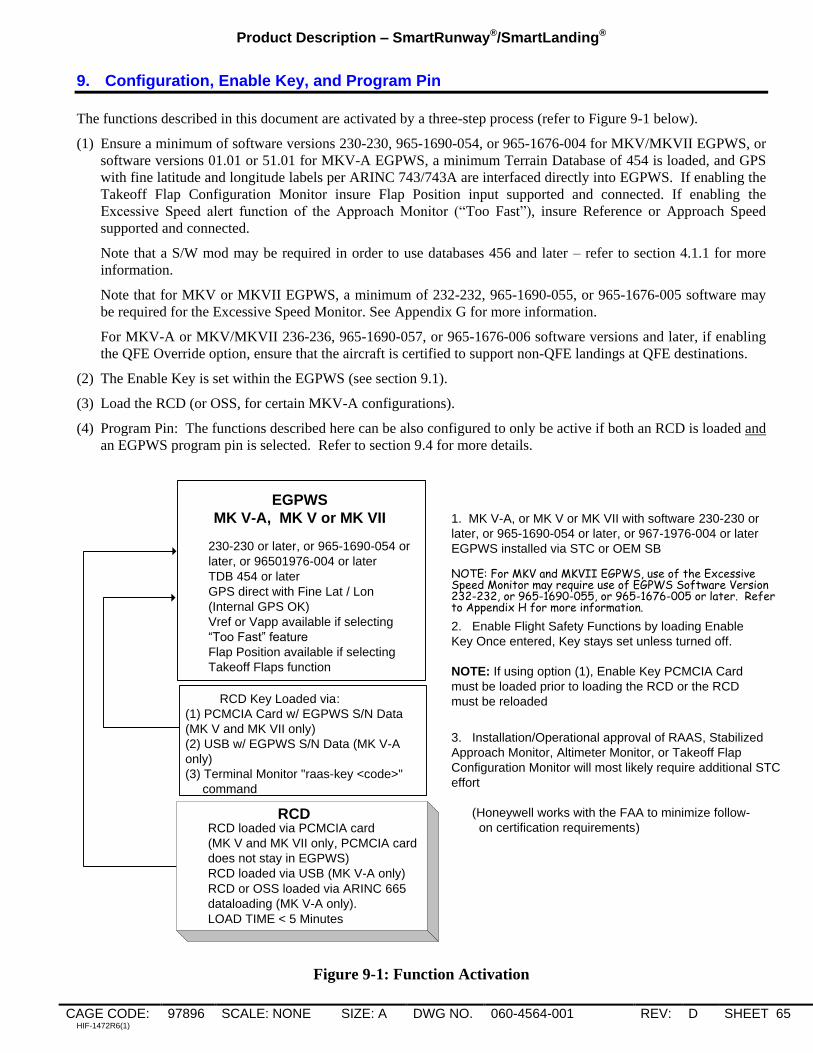
Product Description – SmartRunway®/SmartLanding®
CAGE CODE: 97896 SCALE: NONE SIZE: A DWG NO. 060-4564-001 REV: D SHEET 65 HIF-1472R6(1)
9. Configuration, Enable Key, and Program Pin
The functions described in this document are activated by a three-step process (refer to Figure 9-1 below).
(1) Ensure a minimum of software versions 230-230, 965-1690-054, or 965-1676-004 for MKV/MKVII EGPWS, or
software versions 01.01 or 51.01 for MKV-A EGPWS, a minimum Terrain Database of 454 is loaded, and GPS
with fine latitude and longitude labels per ARINC 743/743A are interfaced directly into EGPWS. If enabling the
Takeoff Flap Configuration Monitor insure Flap Position input supported and connected. If enabling the
Excessive Speed alert function of the Approach Monitor (“Too Fast”), insure Reference or Approach Speed
supported and connected.
Note that a S/W mod may be required in order to use databases 456 and later – refer to section 4.1.1 for more
information.
Note that for MKV or MKVII EGPWS, a minimum of 232-232, 965-1690-055, or 965-1676-005 software may
be required for the Excessive Speed Monitor. See Appendix G for more information.
For MKV-A or MKV/MKVII 236-236, 965-1690-057, or 965-1676-006 software versions and later, if enabling
the QFE Override option, ensure that the aircraft is certified to support non-QFE landings at QFE destinations.
(2) The Enable Key is set within the EGPWS (see section 9.1).
(3) Load the RCD (or OSS, for certain MKV-A configurations).
(4) Program Pin: The functions described here can be also configured to only be active if both an RCD is loaded and
an EGPWS program pin is selected. Refer to section 9.4 for more details.
2. Enable Flight Safety Functions by loading Enable
Key Once entered, Key stays set unless turned off.
NOTE: If using option (1), Enable Key PCMCIA Card
must be loaded prior to loading the RCD or the RCD
must be reloaded
230-230 or later, or 965-1690-054 or
later, or 96501976-004 or later
TDB 454 or later
GPS direct with Fine Lat / Lon
(Internal GPS OK)
Vref or Vapp available if selecting
“Too Fast” feature
Flap Position available if selecting
Takeoff Flaps function
EGPWS
MK V-A, MK V or MK VII 1. MK V-A, or MK V or MK VII with software 230-230 or
later, or 965-1690-054 or later, or 967-1976-004 or later
EGPWS installed via STC or OEM SB
NOTE: For MKV and MKVII EGPWS, use of the Excessive Speed Monitor may require use of EGPWS Software Version 232-232, or 965-1690-055, or 965-1676-005 or later. Refer to Appendix H for more information.
3. Installation/Operational approval of RAAS, Stabilized
Approach Monitor, Altimeter Monitor, or Takeoff Flap
Configuration Monitor will most likely require additional STC
effort
(Honeywell works with the FAA to minimize follow-
on certification requirements)RCD loaded via PCMCIA card
(MK V and MK VII only, PCMCIA card
does not stay in EGPWS)
RCD loaded via USB (MK V-A only)
RCD or OSS loaded via ARINC 665
dataloading (MK V-A only).
LOAD TIME < 5 Minutes
RCD
RCD Key Loaded via:
(1) PCMCIA Card w/ EGPWS S/N Data
(MK V and MK VII only)
(2) USB w/ EGPWS S/N Data (MK V-A
only)
(3) Terminal Monitor "raas-key <code>"
command
Figure 9-1: Function Activation
Product Description – SmartRunway®/SmartLanding®
CAGE CODE: 97896 SCALE: NONE SIZE: A DWG NO. 060-4564-001 REV: D SHEET 66 HIF-1472R6(1)
9.1 Enable Key
In order for the EGPWS to recognize the RCD, an enabling “Key” must be set. This key is based on EGPWS part
number and serial number and once set, stays active within the EGPWS. The RCD Enable Key is set by one of two
methods:
(1) Enable key on PCMCIA Card (MKV or MKVII EGPWS) or USB mass storage device (MKV-A EGPWS).
(2) Enable Key Code set via the EGPWS RS-232 Terminal Monitor interface. This key code is an eight
alphanumeric character string.
The Level 3 Self-Test message “RUNWAY AWARENESS ENABLE SET” is annunciated to confirm that the Enable
Key is set.
The enable key PCMCIA card, USB file, or key code is provided by Honeywell when the customer orders any of the
safety functions described in this document and provides EGPWS part number and serial number information. Note
that the enable key can be cleared for troubleshooting or if the unit is repaired.
9.2 Reloadable Customer Definitions (RCD)
The final step to enabling the Flight Safety Functions described herein is to load an option-specific customer
definitions file which functions much like a set of hardware program pins. This file is referred to as Reloadable
Customer Definitions (RCD). Certain MKV-A configurations may use an Option Selection Software (OSS) file to
configuration SmartRunway/SmartLanding in place of the RCD; the following description is applicable to both the
RCD and the OSS.
Configuration options when downloaded become part of a specific Line Replaceable Unit (LRU). The RCD allows
for the setting of common fleet options as well as GPS antenna position and defining the nominal runway lengths for
multiple aircraft types. Each RCD can support up to 20 different aircraft types. Thus an operator with a mixed fleet
of aircraft can swap EGPWS LRUs within the fleet and will not be required to reload RCDs to keep the nominal
runway lengths correct across the fleet. The RCD can also be used to support customers operating both MK V and
MK VII EGPWS on mixed fleets.
The RCD is divided into 2 parts:
(1) Global Options. Global Options are applicable across the board for each individual function, and will be the same
for all aircraft types programmed in the RCD. Refer to the options summary section for each function.
(2) Aircraft-Type Options define aircraft–specific parameters such as nominal runway lengths for take-off and
landing advisories and GPS antenna location. Refer to the options summary section for each function.
Whenever any of the flight safety features are ordered, a worksheet will be provided, or one can be accessed via the
EGPWS website (www.egpws.com), completed, and sent electronically to Honeywell for RCD creation.
Each RCD is composed of a set of configuration options. Each RCD is assigned a unique part number. In cases
where customers select the same option set on the same EGPWS and aircraft type, they will receive the same RCD
(same RCD Part Number).
The installed RCD part number can be verified by several methods:
(1) An abbreviated RCD part number is displayed on the terrain display during level 1 Self-Test. The last 5-digits
of the software part number are displayed.
(2) The complete 10-digit RCD software part number is annunciated during level 3 Self-Test or can be displayed
using the EGPWS RS-232 Terminal Monitor “Present Status” command.

Product Description – SmartRunway®/SmartLanding®
CAGE CODE: 97896 SCALE: NONE SIZE: A DWG NO. 060-4564-001 REV: D SHEET 67 HIF-1472R6(1)
9.3 Incorporation of the Pilot’s Point of View
There are number of functions that use GPS Antenna location on the aircraft. These are Approaching Runway – On
Ground, Distance Remaining Land and Roll-Out, Distance Remaining Rejected Take-Off, Runway End, and Deep
Landing. In addition to the actual distance from the nose of the aircraft to the GPS antenna, the Pilot‟s Point of
View (PpoV) offset should also be taken into account. The Pilot‟s Point of View is the distance in front of the
aircraft which is not normally visible to the flight crew when sitting in the cockpit. Adding this distance to the
antenna distance results in the callouts occurring earlier and helps ensure that related reference points on the ground
are visible to the flight crew when a corresponding RAAS callout is generated. This is accomplished by the
following calculation:
GPS Antenna Location on aircraft = Pilot‟s Point of View (PpoV ) offset + the Distance from aircraft nose
to the GPS Antenna as specified in the RCD worksheets
This computation is done as part of the RCD generation. It provides the ability for these specific annunciations to be
given relative to where the pilot is looking and is specifically related to an aircraft‟s geometry.
The Pilot‟s Point of View is depicted below:
Tables 9-1 and 9-2 list the aircraft specific PPoV offset from the nose of the aircraft to the point on ground that the
pilot can see.
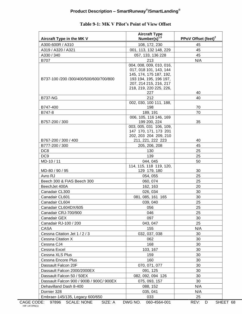
Product Description – SmartRunway®/SmartLanding®
CAGE CODE: 97896 SCALE: NONE SIZE: A DWG NO. 060-4564-001 REV: D SHEET 68 HIF-1472R6(1)
Table 9-1: MK V Pilot’s Point of View Offset
Aircraft Type in the MK V Aircraft Type Number(s)
1,5 PPoV Offset (feet)
2
A300-600R / A310 108, 172, 230 45
A319 / A320 / A321 001, 113, 132 148, 229 45
A330 / 340 057, 133, 136 228 45
B707 213 N/A
B737-100 /200 /300/400/500/600/700/800
004, 008, 009, 010, 016, 017, 018 101, 143, 144 145, 174, 175 187, 192, 193 194, 195, 196 197, 207, 214 215, 216, 217 218, 219, 220 225, 226,
227 40
B737-NG 212 40
B747-400 002, 030, 100 111, 188,
198 70
B747-8 189, 191 70
B757-200 / 300 006, 105, 116 146, 169
199 200, 224 35
B767-200 / 300 / 400
003, 005, 031 106, 109, 147 170, 171, 173 201 202, 203 204 209, 210
211, 221, 222 223 40
B777-200 / 300 205, 206, 208 45
DC8 130 25
DC9 139 25
MD-10 / 11 044, 045 50
MD-80 / 90 / 95 114, 115, 118 119, 120,
129 179, 180 30
Avro RJ 054, 055 25
Beech 300 & FIAS Beech 300 060, 074 25
BeechJet 400A 162, 163 20
Canadair CL300 026, 034 30
Canadair CL601 081, 085, 161 165 30
Canadair CL604 039, 040 25
Canadair CL604DX/605 056 25
Canadair CRJ-700/900 046 25
Canadair GEX 097 30
Canadair RJ-100 / 200 043, 047 25
CASA 155 N/A
Cessna Citation Jet 1 / 2 / 3 032, 037, 038 30
Cessna Citation X 062 30
Cessna CJ4 168 30
Cessna Excel 103, 167 30
Cessna XLS Plus 159 30
Cessna Encore Plus 160 30
Dassault Falcon 20F 070, 071, 077 30
Dassault Falcon 2000/2000EX 091, 125 30
Dassault Falcon 50 / 50EX 082, 092, 094 126 30
Dassault Falcon 900 / 900B / 900C/ 900EX 075, 093, 157 30
Dehavilland Dash 8-400 088, 152 N/A
Dornier 328 035, 041 N/A
Embraer-145/135, Legacy 600/650 033 25

Product Description – SmartRunway®/SmartLanding®
CAGE CODE: 97896 SCALE: NONE SIZE: A DWG NO. 060-4564-001 REV: D SHEET 69 HIF-1472R6(1)
Aircraft Type in the MK V Aircraft Type Number(s)
1,5 PPoV Offset (feet)
2
FIAS CL601/3R & Learjet 60 076, 142 30
FIAS Learjet 60 w/ reactive Windshear 080 20
Fokker 100 131 N/A
Gulfstream G-II / IIB / III / IV / V 068, 069, 079 087, 096,
104 35
Gulfstream G-200 089, 154 25
Gulfstream G-100 / 150 090, 156, 177 20
Hawker 800C/800S/800SF 065, 066, 073, 138 15
Hawker 800XP 176 15
Hawker 1000 067 20
Hawker Horizon/4000 110 20
Honeywell: Beechcraft King Air C-90 064, 098, 128 25
Honeywell: Sabre 65 117 25
Lear 45 102, 166 30
Lear 60 078 20
Premier 1 112 N/A
RC-135 134 N/A
SAAB 2000 036 N/A
Tupelov TU-204 / 214 158 45
Antonov AN-148-100 158 30
Test Aircraft Types 000, 063, 095 099 N/A
Lockheed C-130 123, 150 N/A
Lockheed C-5 137 N/A
MKVIII Emulation 0 N/A
NIMROD MRA4 122 N/A
VC-135 Speckled Trout 153 N/A
KC-135 135 N/A

Product Description – SmartRunway®/SmartLanding®
CAGE CODE: 97896 SCALE: NONE SIZE: A DWG NO. 060-4564-001 REV: D SHEET 70 HIF-1472R6(1)
Table 9-2: MK VII Pilot’s Point of View Offset
Aircraft Type in the MK VII Aircraft Type Number(s)
1,5 PPoV Offset (feet)
2
A300-B2/B4 058 45
B727-100 / 200 005
3 4, 006, 019, 020 041, 054 40
B737-200 040 40
B747-100 / 200 / 300 016, 042, 052 70
B747-SP 059 70
DC8 043, 053, 062 25
DC9 013, 060, 061 25
DC10-10/30/40 011, 014, 023 027 50
ASTRA SP 050 35
Canadair CL600 044 30
Canadair CL601 045 30
Cessna Citation II/550 068 30
Cessna Citation V/Ultra 028, 029 30
Cessna Citation III / VI / VII 030 30
Cessna Citation Bravo 031 30
Cessna Citation Encore 066 30
Convair 0033 4
45
Dassault Falcon 10 / 100 055, 0044 30
Dassault Falcon 20F 034, 035 , 0044 30
Dassault Falcon 200 067, 0044 30
Dassault Falcon 50 / 50EX 036, 0044 30
Gulfstream G-II / IIB / III 038, 039 35
Hawker 700 0083, 009
3, 010
3 N/A
Hawker 800 0083, 009
3, 010
3 15
Honeywell: Beechcraft King Air C-90 056, 063 25
Jetstar II 069 N/A
Lear 31A 037 20
Lear 35 / 55 032, 033, 047 N/A
Lockheed L1011 0053 4
, 057 45
Westwind II 051 N/A
Test Aircraft Types 000, 001, 002 003
3 4,
0043 4
, 0053 4
, 0074 N/A
C-141 48 N/A
C-2A 65 N/A
Lockheed C-130 49 30
VP/UP-3 64 N/A
1 The Aircraft Type Number references specific aircraft which the EGPWS MKV/VII currently support.
2 N/A means that information is not yet available to determine the Pilot Point of View Offset for that specific
aircraft type.
3 This aircraft type is listed more than once because there are different customers that use this aircraft type
and, therefore, may require different Pilot Point of View Offset values.
4 Aircraft types 003, 004, 005, and 007 are a non-Windshear aircraft configurations that can be used by any
compatible aircraft, meaning there can be a different Pilot Point of View Offset value among the various
users of these aircraft types. The user of this table should reference a similar Windshear activated aircraft
type to obtain the PPoV that can be used with the non-Windshear configuration.

Product Description – SmartRunway®/SmartLanding®
CAGE CODE: 97896 SCALE: NONE SIZE: A DWG NO. 060-4564-001 REV: D SHEET 71 HIF-1472R6(1)
5 MKV-A installations have the option to set program pin options through loadable software files (either an
APD - Aircraft Personality Database, or OSS - Option Selection Software) instead of the hardware program
pins used on the MKV and MKVII EGPWS. If the MKV-A is configured in this manner, the aircraft type ID
number will be the legacy (MKV, MKVII) aircraft type number plus 500. For example, the Boeing 737-NG
is type number 212 on MKV, MKVII, or MKV-A when configured using only hardware program pins. On
MKV-A configured using a loadable configuration definition file (APD or OSS), the Boeing 737-NG is type
number 712.
Product Description – SmartRunway®/SmartLanding®
CAGE CODE: 97896 SCALE: NONE SIZE: A DWG NO. 060-4564-001 REV: D SHEET 72 HIF-1472R6(1)
9.4 RCD Program Pin
The functions described in this document are typically enabled via loading an RCD into the EGPWC. And, as has
been discussed herein, some of the RCD based functions can be defined to have an enable discrete, or an inhibit
discrete, but not both for MKV and MKVII EGPWS.
However, if it is desired to have an inhibit switch, and also only enable these functions on specific tail numbers, a
method to require a program pin be selected is available with the MKV-A or MKV EGPWS (not the MKVII).
Strapping details for this program pin are found in Appendix D-15 of the Interface Control Document for the Mark V
Enhanced Ground Proximity Warning System (MKV EGPWS), Honeywell Document, 993-0976-401, Revision AC
or later, or in the Interface Control Document for the MKV-A EGPWS (Honeywell Document SYS69000940-700).
The MKV-A EGPWS can be configured to support both an inhibit and an enable discrete, but for consistency with
the MKV, may also use the method described above.
Please note that the RCD has to be defined to use this program pin. This enabling option is not included on the RCD
Worksheet and will be treated as a special request.
9.5 Visual Message Options
There are several options to overlay visual text messages for advisories and cautions on the Terrain Display, and
several examples of this overlay are contained within this document - see Figure 5-1 for one example. Appendix B
through F specifies the exact text used for all messages.
Via the RCD worksheet the customer can select from one of the following options:
1) No Text overlay messages
2) Display messages for all advisories and cautions described in this document.
3) Display messages just for all Non-Routine advisories (and cautions) described in this document.
4) Display messages just for the cautions described in this document.
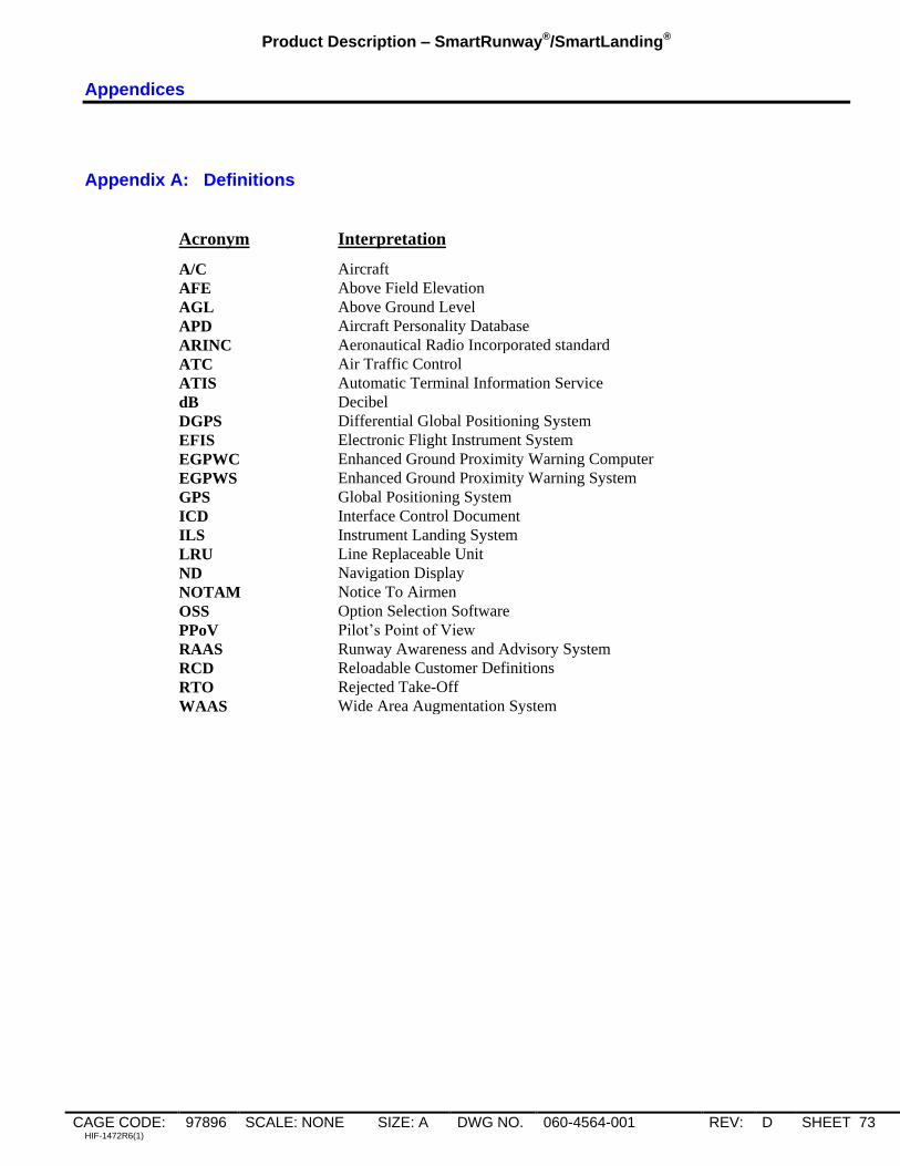
Product Description – SmartRunway®/SmartLanding®
CAGE CODE: 97896 SCALE: NONE SIZE: A DWG NO. 060-4564-001 REV: D SHEET 73 HIF-1472R6(1)
Appendices
Appendix A: Definitions
Acronym Interpretation
A/C Aircraft
AFE Above Field Elevation
AGL Above Ground Level
APD Aircraft Personality Database
ARINC Aeronautical Radio Incorporated standard
ATC Air Traffic Control
ATIS Automatic Terminal Information Service
dB Decibel
DGPS Differential Global Positioning System
EFIS Electronic Flight Instrument System
EGPWC Enhanced Ground Proximity Warning Computer
EGPWS Enhanced Ground Proximity Warning System
GPS Global Positioning System
ICD Interface Control Document
ILS Instrument Landing System
LRU Line Replaceable Unit
ND Navigation Display
NOTAM Notice To Airmen
OSS Option Selection Software
PPoV Pilot‟s Point of View
RAAS Runway Awareness and Advisory System
RCD Reloadable Customer Definitions
RTO Rejected Take-Off
WAAS Wide Area Augmentation System

Product Description – SmartRunway®/SmartLanding®
CAGE CODE: 97896 SCALE: NONE SIZE: A DWG NO. 060-4564-001 REV: D SHEET 74 HIF-1472R6(1)
Appendix B: Runway Awareness and Advisory System Visuals, Aurals and Volume Levels
Table B-1 lists RAAS messages, both aural and visual. Typically RAAS aurals are issued at one of three volume
levels:
(1) By default the In-Air and On-Ground Advisories except Distance Remaining and Taxiway Takeoff
Advisories are issued 6 dB below the volume level of the EGPWS Cautions and Warnings defined by the
Program Pin strapping. However, these volume levels can be adjusted differently via the RCD.
(2) By default the RAAS Cautions and Distance Remaining Advisories are issued at the same volume level as
EGPWS Cautions and Warnings defined by the Program Pin strapping. However, these volume levels can be
adjusted differently via the RCD.
(3) By default the Taxiway Takeoff Caution/Advisory is issued at the EGPWS Cautions and Warnings volume
level listed in item (2) above, plus 3dB. However, the volume level can be adjusted differently via the RCD.
RAAS Self-Test messages are integrated into the existing EGPWS Self-Test functions. RAAS Self-Test
messages are issued at the same volume as existing EGPWS Self-Test messages (6dB lower than the EGPWS
Cautions and Warnings defined by the Program Pin strapping).
For MK V-A EGPWS, or MK V/MK VII EGPWS with software version -236-236, -057, -006 and later an option
is provided to coordinate the Self Test Level 1 audio with the status from a single RAAS Monitor discrete. If the
customer elects to install a RAAS Monitor discrete which reflects the status of all the enabled SmartRunway®
and SmartLanding® alert monitors this option should be selected.
Examples of behavior with option set:
If Stabilized Approach Monitor only is enabled, the self-test level 1 will annunciate:
RUNWAY AWARENESS OK
If Stabilized Approach Monitor and RAAS are enabled, the self-test level 1 will annunciate:
RUNWAY AWARENESS OK, [UNITS]
If Stabilized Approach Monitor/RAAS is enabled and unavailable, the self-test level 1 will
annunciate:
RUNWAY AWARENESS NOT AVAILABLE
If Stabilized Approach Monitor/RAAS is enabled and is inoperative, the self-test level 1 will
annunciate:
RUNWAY AWARENESS INOP
Table B-2 provides a listing of RAAS maintenance messages.
Table B-3 lists displayed RAAS status messages.
Figure B-1 describes the RAAS Caution Lamp.
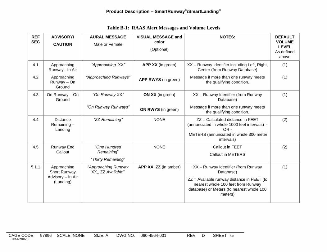
Product Description – SmartRunway®/SmartLanding®
CAGE CODE: 97896 SCALE: NONE SIZE: A DWG NO. 060-4564-001 REV: D SHEET 75 HIF-1472R6(1)
Table B-1: RAAS Alert Messages and Volume Levels
REF
SEC
ADVISORY/
CAUTION
AURAL MESSAGE
Male or Female
VISUAL MESSAGE and
color
(Optional)
NOTES: DEFAULT
VOLUME
LEVEL
As defined
above
4.1
4.2
Approaching
Runway - In Air
Approaching
Runway – On
Ground
“Approaching XX”
“Approaching Runways”
APP XX (in green)
APP RWYS (in green)
XX – Runway Identifier including Left, Right,
Center (from Runway Database)
Message if more than one runway meets
the qualifying condition.
(1)
(1)
4.3 On Runway – On
Ground
“On Runway XX”
“On Runway Runways”
ON XX (in green)
ON RWYS (in green)
XX – Runway Identifier (from Runway
Database)
Message if more than one runway meets
the qualifying condition.
(1)
4.4 Distance
Remaining –
Landing
“ZZ Remaining” NONE ZZ = Calculated distance in FEET
(annunciated in whole 1000 feet intervals) -
OR -
METERS (annunciated in whole 300 meter
intervals)
(2)
4.5 Runway End
Callout
“One Hundred
Remaining”
“Thirty Remaining”
NONE Callout in FEET
Callout in METERS
(2)
5.1.1 Approaching
Short Runway
Advisory – In Air
(Landing)
“Approaching Runway
XX,, ZZ Available”
APP XX ZZ (in amber)
XX – Runway Identifier (from Runway
Database)
ZZ = Available runway distance in FEET (to
nearest whole 100 feet from Runway
database) or Meters (to nearest whole 100
meters)
(1)

Product Description – SmartRunway®/SmartLanding®
CAGE CODE: 97896 SCALE: NONE SIZE: A DWG NO. 060-4564-001 REV: D SHEET 76 HIF-1472R6(1)
5.1.2 Approaching
Short Runway
Caution– In Air
(Landing)
“Caution, Short Runway
Short Runway” SHORT RUNWAY
(in amber)
(2)
5.2.1 Insufficient
Runway Length –
On Ground
(Takeoff)
“On Runway XX, ZZ
Remaining”
ON XX ZZ (in amber)
XX – Runway Identifier (from Runway
Database)
ZZ = Available runway distance in FEET (to
nearest whole 100 feet from Runway
database) or Meters (to nearest whole 100
meters)
(1)
5.2.2 Insufficient
Runway Length
Caution – On
Ground (Takeoff)
“Caution, Short Runway
Short Runway” SHORT RUNWAY
(in amber)
(2)
5.3 Extended Holding
- On Runway
“On Runway XX – On
Runway XX ”
ON XX (in amber) XX – Runway Identifier (from Runway
Database)
(1)
5.4.1 Taxiway Takeoff
Advisory
“On Taxiway! On
Taxiway!” ON TAXIWAY
(in amber)
(3)
5.4.2 Taxiway Takeoff
Caution
“Caution, On Taxiway!
On Taxiway!” ON TAXIWAY
(in amber)
(3)
5.5 Distance
Remaining –
Rejected Takeoff
“ZZ Remaining” NONE ZZ = Calculated distance in FEET
(annunciated in whole 1000 feet intervals) -
OR -
METERS (annunciated in whole 300 meter
intervals)
(2)
5.6 Taxiway Landing
Caution
“Caution, Taxiway!,
Caution Taxiway!”
TAXIWAY
(in amber)
(2)

Product Description – SmartRunway®/SmartLanding®
CAGE CODE: 97896 SCALE: NONE SIZE: A DWG NO. 060-4564-001 REV: D SHEET 77 HIF-1472R6(1)
Table B-2: RAAS Maintenance Messages
MAINT.
FUNCTION
MESSAGE
Except where noted, all maintenance
message voices are Male
NOTES:
All volume levels at same volume as
existing EGPWS Self-Test messages
Self-Test Level 1
(Annunciated
after Terrain
Awareness part
of Self-Test)
“Runway Awareness OK - Feet”
“Runway Awareness OK - Meters”
Note: Feet and Meters will be annunciated
in the gender voice option (Male or Female)
selected for RAAS.
RAAS enabled, functioning, has good
position information, and is at a validated
airport. Distances annunciated in Feet.
RAAS enabled, functioning, has good
position information, and is at a validated
airport. Distances annunciated in Meters.
Self-Test Level 1 “Runway Awareness Not Available”
RAAS enabled, but the system either has
no position information, the accuracy of the
position information is insufficient to allow
RAAS to function, or the aircraft is at airport
that has not been validated in the EGPWS
Terrain Database
Self-Test Level 1 “Runway Awareness Inhibited” RAAS enabled, but the advisories have
been inhibited with the activation of an
external discrete.
Optional via RCD: RAAS or Stabilized
Approach Monitor or Altimeter Monitor
inhibited
Self-Test Level 1 “Runway Awareness INOP” RAAS enabled but the function is
inoperative
Self-Test Level 1 “Runway Awareness R-T-O” RAAS enabled and functioning, but RAAS
advisories (other than distance remaining)
are temporarily inhibited because RAAS
has detected a Rejected Take-Off
condition. To clear this message and
enable RAAS advisories, the aircraft must
be taxied off the runway area.
Self-Test Level 3
(Annunciated at
end of Selected
Options )
“Runway Awareness Enable Set” RCD Enable Key is set. The RCD is not
loaded.
Self-Test Level 3
(Annunciated at
end of Selected
Options )
“Runway Awareness Enabled” RCD is loaded and RCD Enable Key is set.
Note: This message replaces the “Runway
Awareness Enable Set” message.
Self-Test Level 3 “RCD Part Number XXX-XXXX-XXX” where
X is the 10-digit installation-specific RCD
part number.
Allows verification that the correct RCD is
loaded into the EGPWS.
Self-Test Level 4 “Runway Awareness Inhibit Invalid” In some installations the RAAS Inhibit
switch is configured to cause a fault if left
selected in cruise. This is the fault
message if that occurred.
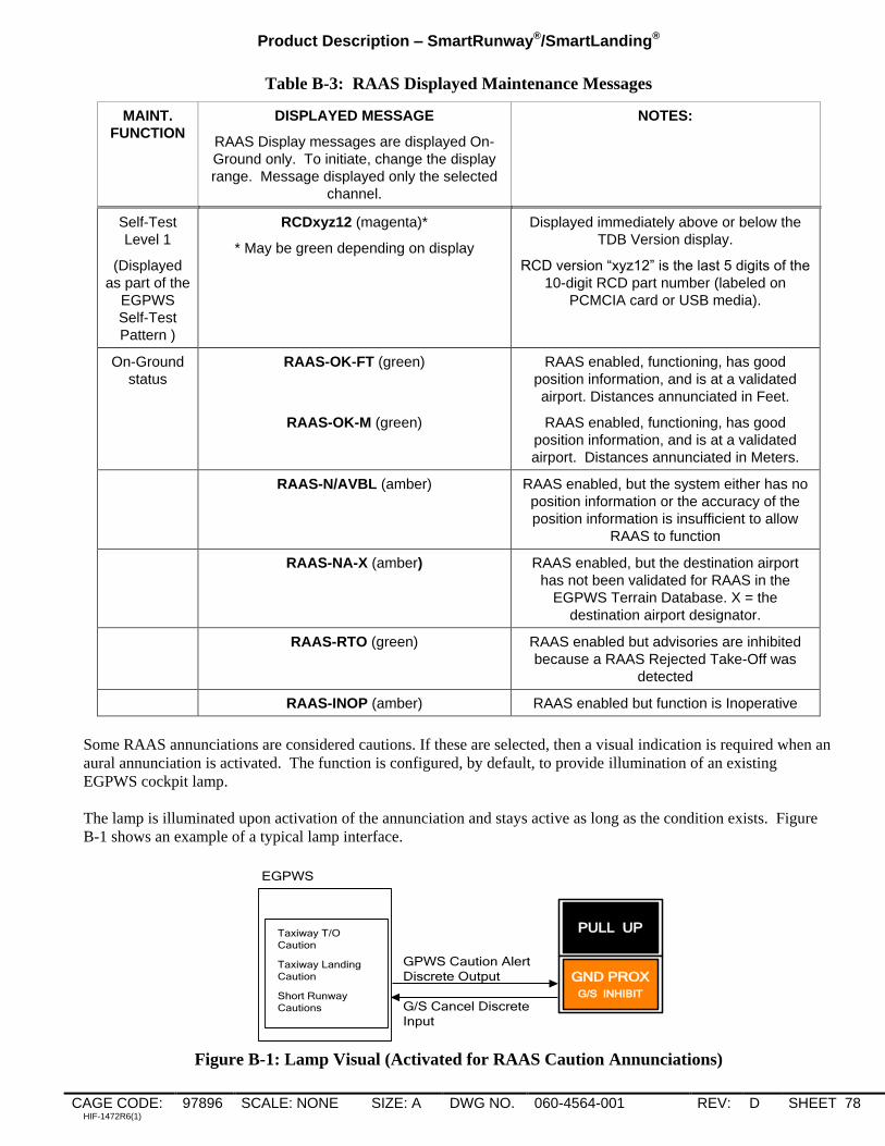
Product Description – SmartRunway®/SmartLanding®
CAGE CODE: 97896 SCALE: NONE SIZE: A DWG NO. 060-4564-001 REV: D SHEET 78 HIF-1472R6(1)
Table B-3: RAAS Displayed Maintenance Messages
MAINT.
FUNCTION
DISPLAYED MESSAGE
RAAS Display messages are displayed On-
Ground only. To initiate, change the display
range. Message displayed only the selected
channel.
NOTES:
Self-Test
Level 1
(Displayed
as part of the
EGPWS
Self-Test
Pattern )
RCDxyz12 (magenta)*
* May be green depending on display
Displayed immediately above or below the
TDB Version display.
RCD version “xyz12” is the last 5 digits of the
10-digit RCD part number (labeled on
PCMCIA card or USB media).
On-Ground
status
RAAS-OK-FT (green)
RAAS-OK-M (green)
RAAS enabled, functioning, has good
position information, and is at a validated
airport. Distances annunciated in Feet.
RAAS enabled, functioning, has good
position information, and is at a validated
airport. Distances annunciated in Meters.
RAAS-N/AVBL (amber) RAAS enabled, but the system either has no
position information or the accuracy of the
position information is insufficient to allow
RAAS to function
RAAS-NA-X (amber) RAAS enabled, but the destination airport
has not been validated for RAAS in the
EGPWS Terrain Database. X = the
destination airport designator.
RAAS-RTO (green) RAAS enabled but advisories are inhibited
because a RAAS Rejected Take-Off was
detected
RAAS-INOP (amber) RAAS enabled but function is Inoperative
Some RAAS annunciations are considered cautions. If these are selected, then a visual indication is required when an
aural annunciation is activated. The function is configured, by default, to provide illumination of an existing
EGPWS cockpit lamp.
The lamp is illuminated upon activation of the annunciation and stays active as long as the condition exists. Figure
B-1 shows an example of a typical lamp interface.
G/S Cancel Discrete
Input
GPWS Caution Alert
Discrete Output
EGPWS
PULL UP
GND PROX
G/S INHIBIT
Taxiway T/O
Caution
Taxiway Landing
Caution
Short Runway
Cautions
Figure B-1: Lamp Visual (Activated for RAAS Caution Annunciations)
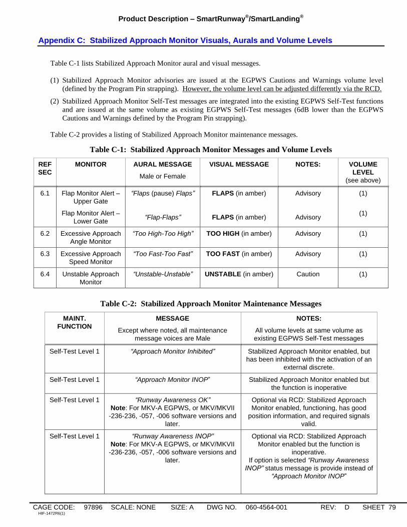
Product Description – SmartRunway®/SmartLanding®
CAGE CODE: 97896 SCALE: NONE SIZE: A DWG NO. 060-4564-001 REV: D SHEET 79 HIF-1472R6(1)
Appendix C: Stabilized Approach Monitor Visuals, Aurals and Volume Levels
Table C-1 lists Stabilized Approach Monitor aural and visual messages.
(1) Stabilized Approach Monitor advisories are issued at the EGPWS Cautions and Warnings volume level
(defined by the Program Pin strapping). However, the volume level can be adjusted differently via the RCD.
(2) Stabilized Approach Monitor Self-Test messages are integrated into the existing EGPWS Self-Test functions
and are issued at the same volume as existing EGPWS Self-Test messages (6dB lower than the EGPWS
Cautions and Warnings defined by the Program Pin strapping).
Table C-2 provides a listing of Stabilized Approach Monitor maintenance messages.
Table C-1: Stabilized Approach Monitor Messages and Volume Levels
REF
SEC
MONITOR AURAL MESSAGE
Male or Female
VISUAL MESSAGE
NOTES: VOLUME
LEVEL
(see above)
6.1
Flap Monitor Alert –
Upper Gate
Flap Monitor Alert –
Lower Gate
“Flaps (pause) Flaps”
“Flap-Flaps”
FLAPS (in amber)
FLAPS (in amber)
Advisory
Advisory
(1)
(1)
6.2 Excessive Approach
Angle Monitor
“Too High-Too High” TOO HIGH (in amber) Advisory (1)
6.3 Excessive Approach
Speed Monitor
“Too Fast-Too Fast” TOO FAST (in amber) Advisory (1)
6.4 Unstable Approach
Monitor
“Unstable-Unstable” UNSTABLE (in amber) Caution (1)
Table C-2: Stabilized Approach Monitor Maintenance Messages
MAINT.
FUNCTION
MESSAGE
Except where noted, all maintenance
message voices are Male
NOTES:
All volume levels at same volume as
existing EGPWS Self-Test messages
Self-Test Level 1 “Approach Monitor Inhibited” Stabilized Approach Monitor enabled, but
has been inhibited with the activation of an
external discrete.
Self-Test Level 1 “Approach Monitor INOP” Stabilized Approach Monitor enabled but
the function is inoperative
Self-Test Level 1
“Runway Awareness OK”
Note: For MKV-A EGPWS, or MKV/MKVII
-236-236, -057, -006 software versions and
later.
Optional via RCD: Stabilized Approach
Monitor enabled, functioning, has good
position information, and required signals
valid.
Self-Test Level 1
“Runway Awareness INOP”
Note: For MKV-A EGPWS, or MKV/MKVII
-236-236, -057, -006 software versions and
later.
Optional via RCD: Stabilized Approach
Monitor enabled but the function is
inoperative.
If option is selected “Runway Awareness
INOP” status message is provide instead of
“Approach Monitor INOP”
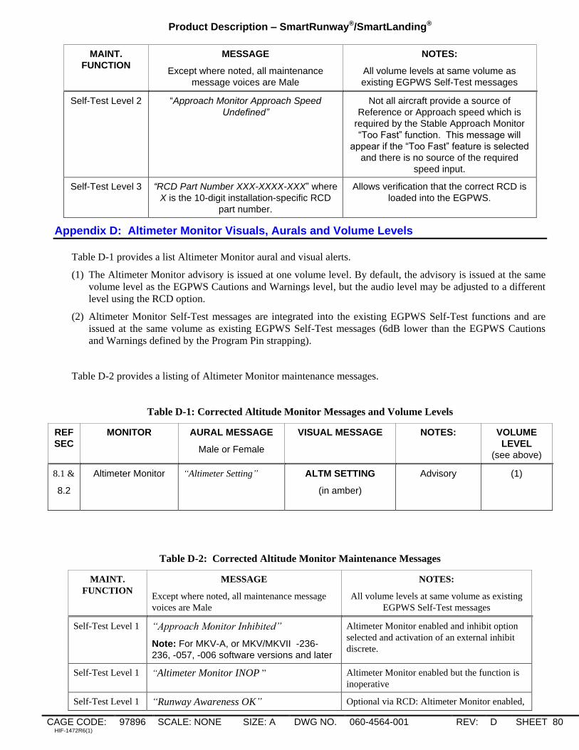
Product Description – SmartRunway®/SmartLanding®
CAGE CODE: 97896 SCALE: NONE SIZE: A DWG NO. 060-4564-001 REV: D SHEET 80 HIF-1472R6(1)
MAINT.
FUNCTION
MESSAGE
Except where noted, all maintenance
message voices are Male
NOTES:
All volume levels at same volume as
existing EGPWS Self-Test messages
Self-Test Level 2 “Approach Monitor Approach Speed
Undefined”
Not all aircraft provide a source of
Reference or Approach speed which is
required by the Stable Approach Monitor
“Too Fast” function. This message will
appear if the “Too Fast” feature is selected
and there is no source of the required
speed input.
Self-Test Level 3 “RCD Part Number XXX-XXXX-XXX” where
X is the 10-digit installation-specific RCD
part number.
Allows verification that the correct RCD is
loaded into the EGPWS.
Appendix D: Altimeter Monitor Visuals, Aurals and Volume Levels
Table D-1 provides a list Altimeter Monitor aural and visual alerts.
(1) The Altimeter Monitor advisory is issued at one volume level. By default, the advisory is issued at the same
volume level as the EGPWS Cautions and Warnings level, but the audio level may be adjusted to a different
level using the RCD option.
(2) Altimeter Monitor Self-Test messages are integrated into the existing EGPWS Self-Test functions and are
issued at the same volume as existing EGPWS Self-Test messages (6dB lower than the EGPWS Cautions
and Warnings defined by the Program Pin strapping).
Table D-2 provides a listing of Altimeter Monitor maintenance messages.
Table D-1: Corrected Altitude Monitor Messages and Volume Levels
REF
SEC
MONITOR AURAL MESSAGE
Male or Female
VISUAL MESSAGE
NOTES: VOLUME
LEVEL
(see above)
8.1 &
8.2
Altimeter Monitor “Altimeter Setting” ALTM SETTING
(in amber)
Advisory
(1)
Table D-2: Corrected Altitude Monitor Maintenance Messages
MAINT.
FUNCTION
MESSAGE
Except where noted, all maintenance message
voices are Male
NOTES:
All volume levels at same volume as existing
EGPWS Self-Test messages
Self-Test Level 1 “Approach Monitor Inhibited”
Note: For MKV-A, or MKV/MKVII -236-
236, -057, -006 software versions and later
Altimeter Monitor enabled and inhibit option
selected and activation of an external inhibit
discrete.
Self-Test Level 1 “Altimeter Monitor INOP ” Altimeter Monitor enabled but the function is
inoperative
Self-Test Level 1 “Runway Awareness OK” Optional via RCD: Altimeter Monitor enabled,

Product Description – SmartRunway®/SmartLanding®
CAGE CODE: 97896 SCALE: NONE SIZE: A DWG NO. 060-4564-001 REV: D SHEET 81 HIF-1472R6(1)
MAINT.
FUNCTION
MESSAGE
Except where noted, all maintenance message
voices are Male
NOTES:
All volume levels at same volume as existing
EGPWS Self-Test messages
Note: For MKV-A, or MKV/MKVII -236-
236, -057, -006 software versions and later
functioning, and required signals valid.
Self-Test Level 1
“Runway Awareness INOP”
Note: For MKV-A, or MKV/MKVII -236-
236, -057, -006 software versions and later
Optional via RCD: Approach Monitor enabled
but the function is inoperative.
If option is selected “Runway Awareness
INOP” status message is provided instead of
“Altimeter Monitor INOP ”
Self-Test Level 2 “Altimeter Monitor GPS Signal Undefined” The Altimeter Monitor requires a GPS input.
This message will appear if the monitor is
selected and there is no source of GPS.
Self-Test Level 2 “Altimeter Monitor Static Air Temperature
Undefined”
The Altimeter Monitor requires a SAT input.
This message will appear if the monitor is
selected and there is no source of SAT.
Self-Test Level 3 “RCD Part Number XXX-XXXX-XXX” where X
is the 10-digit installation-specific RCD part
number.
Allows verification that the correct RCD is
loaded into the EGPWS.

Product Description – SmartRunway®/SmartLanding®
CAGE CODE: 97896 SCALE: NONE SIZE: A DWG NO. 060-4564-001 REV: D SHEET 82 HIF-1472R6(1)
Appendix E: Takeoff Flap Configuration Monitor Visuals, Aurals and Volume Levels
Table E-1 provides a list of Takeoff Flap Configuration Monitor aural and visual alerts.
(1) The Takeoff Flap Configuration Monitor is issued at one volume level. By default, the advisory is issued at
the same volume level as the EGPWS Cautions and Warnings level, but the audio level may be adjusted to a
different level using the RCD option.
(2) Takeoff Flap Configuration Monitor Self-Test messages are integrated into the existing EGPWS Self-Test
functions and are issued at the same volume as existing EGPWS Self-Test messages (6dB lower than the
EGPWS Cautions and Warnings defined by the Program Pin strapping). However, the volume level can be
adjusted differently via the RCD.
Table E-2 provides a listing of Takeoff Flap Configuration Monitor maintenance messages.
Table E-1: Takeoff Flap Configuration Monitor Aural Messages
REF
SEC
MONITOR AURAL MESSAGE
Male or Female
VISUAL MESSAGE
NOTES: VOLUME
LEVEL
(see above)
9.1
Takeoff Flap
Configuration
Monitor
“Flaps-Flaps” FLAPS (in amber) Caution (1)
Table E-2: Takeoff Flap Configuration Monitor Maintenance Messages
MAINT.
FUNCTION
MESSAGE
Except where noted, all maintenance message
voices are Male
NOTES:
All volume levels at same volume as existing
EGPWS Self-Test messages
Self-Test Level 1 “Flaps Monitor Inhibited” Takeoff Flap Configuration Monitor enabled
but the function is inhibited
Self-Test Level 1 “Flaps Monitor INOP ” Takeoff Flap Configuration Monitor enabled
but the function is inoperative
Self-Test Level 1
“Runway Awareness INOP”
Note: For MKV-A, or MKV/MKVII -236-
236, -057, -006 software versions and later
Optional via RCD: Takeoff Flap Configuration
Monitor enabled but the function is
inoperative.
If option is selected “Runway Awareness
INOP” status message is provide instead of
“Flaps Monitor INOP ”
Self-Test Level 2 “Flaps Monitor - Flap Angle Undefined” Not all aircraft provide a source of Flap
Position which is required by the Takeoff Flap
Configuration Monitor. This message will
appear if the Takeoff Flap Configuration
Monitor is selected and there is no source of
the required input.
Self-Test Level 3 “RCD Part Number XXX-XXXX-XXX” where X
is the 10-digit installation-specific RCD part
number.
Allows verification that the correct RCD is
loaded into the EGPWS.

Product Description – SmartRunway®/SmartLanding®
CAGE CODE: 97896 SCALE: NONE SIZE: A DWG NO. 060-4564-001 REV: D SHEET 83 HIF-1472R6(1)
Appendix F: Long Landing Monitor Visuals, Aurals and Volume Levels
Table F-1 provides a list Long Landing Monitor aural and visual alerts.
(1) The Long Landing Monitor is issued at one volume level. By default, the alert is issued at the same volume level
as the EGPWS Cautions and Warnings level. However, the volume level can be adjusted differently via the RCD.
(2) Long Landing Monitor Self-Test messages are integrated into the existing EGPWS Self-Test functions and are
issued at the same volume as existing EGPWS Self-Test messages (6dB lower than the EGPWS Cautions and
Warnings defined by the Program Pin strapping).
Table F-2 provides a listing of Long Landing Monitor maintenance messages.
Table F-1: Long Landing Monitor Displayed Messages
REF
SEC
MONITOR AURAL MESSAGE
Male or Female
VISUAL MESSAGE
NOTES: VOLUME
LEVEL
(see above)
10
Long Landing
Monitor
“Long Landing-Long Landing”
Optional:
“Deep Landing-Deep Landing”
LONG LANDING (in amber)
Optional:
DEEP LANDING (in amber)
If configured overlaid on top of
terrain image. Terrain display
must be selected to see the
visual indication.
Caution
(1)
Table F-2: Long Landing Monitor Maintenance Messages
SAME AS RAAS – SEE APPENDIX B-2.

Product Description – SmartRunway®/SmartLanding®
CAGE CODE: 97896 SCALE: NONE SIZE: A DWG NO. 060-4564-001 REV: D SHEET 84 HIF-1472R6(1)
Appendix G: Aircraft Compatibility Tables
Three of the functions described in this document require inputs that are not present in all aircraft configurations.
These functions are the Stabilized Approach Monitor Excessive Approach Speed function described in section 5, the
Takeoff Flap Configuration Monitor described in section 7, and the Altimeter Monitor described in section 6.
To use the Stabilized Approach Monitor‟s Excessive Speed function, the EGPWS must have a source of Approach or
Reference Speed. For some aircraft, this is not an option, and so the monitor cannot be selected. For other aircraft
types this data may either already be supplied to the EGPWS, or can be supplied, by adding wiring to an ARINC 429
source of the data. Note that the Excessive Speed Monitor is NOT available with installations that use the MKVII
EGPWS.
To use the Takeoff Flap Configuration Monitor, the EGPWS must already be connected to a source of flap position.
Generally speaking, this means most aircraft types that use the Reactive Windshear function of the EGPWS, which
can also require flap position, can select the Takeoff Flap Configuration Monitor (but this is not always the case).
To use the Altimeter Monitor, the EGPWS must already be connected to a source of Static Air Temperature as
defined in the appropriate ICD (MKV-A, MKV, or MKVII).
The following tables identify which aircraft types can, and cannot, select these three monitors. Table G-1 is for the
MKV and MKV-A EGPWS, and Tables G-2 and G-3 are for the MKVII EGPWS.
For the MKV and MKV-A, the table has four columns listed after each aircraft type. An „X‟, „X2‟ or „X3‟ in a
column indicates the following:
1: An ‘X’, ‘X2’ or ‘X3’ in column 1 indicates the aircraft is compatible with the Excessive Speed Monitor with no
wiring changes. That said, the operator must confirm that the FMS supplies the Approach/Reference speed as
defined in the ICD for the aircraft type. (For example, some FMS may only output speed if a Speed Tape
Display option is selected.) An ‘X2’ in column 1 indicates that MKV-A EGPWC or MKV EGPWC p/n 965-0976-
0XX-232-232 or later, or 965-1690-055 or later, or 965-1676-005 or later is required. An ‘X3’ in column 1
indicates that MKV-A EGPWC or MKV EGPWC p/n 965-0976-0XX-234-234 or later is required.
2: An ‘X’ or ‘X2’ in column 2 indicates the aircraft is compatible with the Excessive Speed Monitor with a
wiring change if the FMS supplies the Approach Speeds and Speed Control Mode labels as defined in the ICD
for the aircraft type. An ‘X2’ in column 2 indicates that MKV-A EGPWC or MKV EGPWC p/n 965-0976-0XX-
232-232 or later, or 965-1676-005 or later, or 965-1690-055 or later is required.
3: An ‘X’, ‘X2’ or ‘X3’ in column 3 indicates the aircraft is compatible with Takeoff Flap Configuration Monitor.
However, an ‘X2’ in column 3 indicates that the EGPWS must be program pinned to enable the Reactive
Windshear Function for the Takeoff Flap Configuration Monitor to work. An X3 in the column indicates that
MKV-A EGPWC or MKV EGPWC p/n 965-0976-0XX-234-234 or later is required.
Regarding the compatibility of the Takeoff Flap Configuration Monitor: Potential users must be aware of the critical
importance of the ‘X2” note in column 3. They must confirm the EGPWS is both connected to a source of flap angle as
defined in the EGPWS ICD, and that:
If the Flap Angle signal type is defined in the ICD as ‘Windshear’ and the Reactive Windshear function of the
EGPWS is enabled, then the monitor can be selected.
If the Flap Angle signal type is defined in the ICD as ‘Basic”, then the monitor can be selected regardless of
whether the Reactive Windshear function is enabled or not.
4: An ‘X’ in column 4 indicates the aircraft is compatible with the Altimeter Monitor.
IMPORTANT NOTE: If a full-up ARINC743/743A GPS connection to the EGPWS is not present, then
NONE of the features described in this document are available.

Product Description – SmartRunway®/SmartLanding®
CAGE CODE: 97896 SCALE: NONE SIZE: A DWG NO. 060-4564-001 REV: D SHEET 85 HIF-1472R6(1)
Table G-1: MKV Aircraft Type Compatibility Table
AIRCRAFT TYPE AIRCRAFT
TYPE
NUMBER*
1
2
3
4
Airbus A300-600 (AA) 108 - - - -
Airbus A300-600R/A310 (Production Aircraft) 172 - - - X
Airbus A300-600R/A310 (Mercury GPS Compatible) 230 - - - X
Airbus A318/A319/A320/A321 Alternate Lamp Format 132 - X - X
Airbus A319/A320/A321 (UA) 1 - X - X
Airbus A318/A319/A320/A321 113 - X - X
Airbus A319/A320/A321Contained Popup/ Alternate Lamp Format
(BA)
148 - - - X
Airbus A318/A319/A320/A321 (Mercury GPS Compatible) 229 - - - X
Airbus A330/340 (DLH/Cathay) 133 - X2 - X
Airbus A330/340 OEM 57 - X2 - X
Airbus A330/A340 Alternate Lamp Format 136 - X2 - X
Airbus A330/A340 (Mercury GPS Compatible) 228 - - - X
Avro RJ/BAe 146 with Bendix PPI Display 55 - - - X
Avro RJ/BAe 146 with PPI Display & WXR Scan Control 54 - - - X
Boeing 707 213 X2 - X X
Boeing 737-200 Delta Airlines 187 - - - -
Boeing 737-300 Basic 4 X2 - X2 X
Boeing 737-300 Contained Popup/Alternate Lamp Format (BA) 144 X2 - X2 X
Boeing 737-300 OEM 192 X2 - X2 X
Boeing 737-300 UAL 217 X2 - X2 X
Boeing 737-300 UAL/Alternate Lamp Format 218 X2 - X2 X
Boeing 737-300 with PPI Display 16 X2 - X2 X
Boeing 737-300 with Large Area Display 10 X2 - X2 X
Boeing 737-300 No WXR ON Label (DAL) 174 X2 - X2 X
Boeing 737-300 OEM with Digital Glideslope 214 X2 - X2 X
Boeing 737-400 (AK) 101 X2 - X2 X
Boeing 737-400 Basic 8 X2 - X2 X
Boeing 737-400 Contained Popup/Alternate Lamp Format (BA) 145 X2 - X2 X
Boeing 737-400 OEM 193 X2 - X2 X
Boeing 737-400 UAL 225 X2 - X2 X
Boeing 737-400 UAL/Alternate Lamp Format 226 X2 - X2 X
Boeing 737-400 with PPI Display 18 X2 - X2 X
Boeing 737-400 No WXR ON Label (Lufthansa) 227 X2 - X2 X
Boeing 737-400 OEM with Digital Glideslope 215 X2 - X2 X
Boeing 737-500 Basic 9 X2 - X2 X
Boeing 737-500 Contained Popup/Alternate Lamp Format (BA) 143 X2 - X2 X
Boeing 737-500 Lufthansa 175 X2 - X2 X
Boeing 737-500 OEM 194 X2 - X2 X
Boeing 737-500 UAL 219 X2 - X2 X
Boeing 737-500 UAL/Alternate Lamp Format 220 X2 - X2 X
Boeing 737-500 with PPI Display 17 X2 - X2 X
Boeing 737-500 OEM with Digital Glideslope 216 X2 - X2 X
Boeing 737-600 Integrated 195 X2 - X X
Boeing 737-700 Integrated 196 X2 - X X
Boeing 737-NG Integrated with Windshear Update 212 X - X X
Boeing 737-700 IGW Integrated (BBJ) 207 X2 - X X
Boeing 737-800 Integrated 197 X2 - X X
Boeing 747-400 BA 2 X2 - X2 X

Product Description – SmartRunway®/SmartLanding®
CAGE CODE: 97896 SCALE: NONE SIZE: A DWG NO. 060-4564-001 REV: D SHEET 86 HIF-1472R6(1)
AIRCRAFT TYPE AIRCRAFT
TYPE
NUMBER*
1
2
3
4
Boeing 747-400 JAL Simulator 111 X2 - X2 X
Boeing 747-400 Basic 30 X2 - X2 X
Boeing 747-400 Integrated 198 X2 - X2 X
Boeing 747-400 LCF Integrated 190 X2 - X2 X
Boeing 747-400 Simulator 100 X2 - X2 X
Boeing 747-400 with Display Update 188 X2 - X2 X
Boeing 747-8 Freighter/Passenger 189 X2 - X2 X
Boeing 747-8 Passenger (future use if needed) 191 X2 - X2 X
Boeing 757-200 (AA) 105 X2 - X2 X
Boeing 757-200 Basic 6 X2 - X2 X
Boeing 757-200 Contained Popup (BA) 146 X2 - X2 X
Boeing 757-200 Integrated 199 X2 - X2 X
Boeing 757-200 (Saudi Royal) 116 X2 - X2 X
Boeing 757-200 UAL 224 X2 - X2 X
Boeing 757-200 No WXR ON Label (DAL) 169 X2 - X2 X
Boeing 757-300 Integrated 200 X2 - X2 X
Boeing 767-200 (AA) 106 X2 - X2 X
Boeing 767-200 Basic 31 X2 - X2 X
Boeing 767-200 Integrated 201 X2 - X2 X
Boeing 767-200 Integrated with LFDS 209 X2 - X2 X
Boeing 767-200 UAL 221 X2 - X2 X
Boeing 767-200 No WXR ON Label (DAL) 170 X2 - X2 X
Boeing 767-300 Basic 5 X2 - X2 X
Boeing 767-300 Integrated 202 X2 - X2 X
Boeing 767-300 Integrated with LFDS 210 X2 - X2 X
Boeing 767-300 UAL 223 X2 - X2 X
Boeing 767-300 No WXR ON Label (DAL) 171 X2 - X2 X
Boeing 767-300ER (AA) 109 X2 - X2 X
Boeing 767-300ER Basic 3 X2 - X2 X
Boeing 767-300ER Contained Popup (BA) 147 X2 - X2 X
Boeing 767-300ER Integrated 203 X2 - X2 X
Boeing 767-300ER Integrated with LFDS 211 X2 - X2 X
Boeing 767-300ER UAL 222 X2 - X2 X
Boeing 767-300ER No WXR ON Label (DAL) 173 X2 - X2 X
Boeing 767-400 Integrated 204 X2 - X2 X
Boeing 777-200 Integrated
*requires -232-232 Mod 1
205 X2* - X X
Boeing 777-200LR/300ER Integrated
*requires -232-232 Mod 1
208 X2* - X X
Boeing 777-300 Integrated
*requires -232-232 Mod 1
206 X2* - X X
Bombardier Challenger 300 34 - - X3 X
Bombardier CL-601/3A (Rosemont AOA), Audio On 85 X3 - X X
Bombardier CL-601/3A (Rosemont AOA), TCAS Inhibit 165 X3 - X X
Bombardier CL-601/3A (SafeFlight AOA), Audio On 81 X3 - X X
Bombardier CL-601/3A (SafeFlight AOA), TCAS Inhibit 161 X3 - X X
Bombardier CL-604 39 - - - X
Bombardier CL-604 Integrated 40 - - - X
Bombardier CL-605 Integrated 56 - - - X
Bombardier CRJ-100/200 Non-Integrated 43 - - X3 X
Bombardier CRJ-100/200 Integrated * wiring change required for Flap Angle input.
47 - - X3* X
Bombardier CRJ-700/900 Family 46 - - X3 X
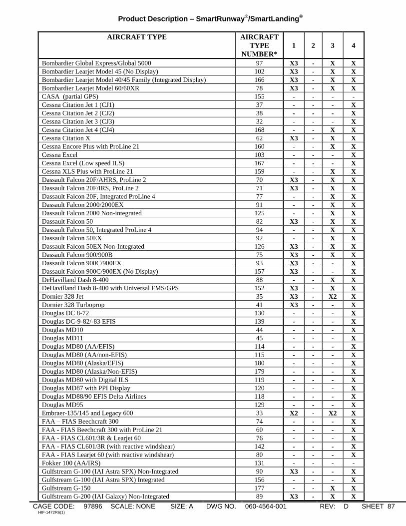
Product Description – SmartRunway®/SmartLanding®
CAGE CODE: 97896 SCALE: NONE SIZE: A DWG NO. 060-4564-001 REV: D SHEET 87 HIF-1472R6(1)
AIRCRAFT TYPE AIRCRAFT
TYPE
NUMBER*
1
2
3
4
Bombardier Global Express/Global 5000 97 X3 - X X
Bombardier Learjet Model 45 (No Display) 102 X3 - X X
Bombardier Learjet Model 40/45 Family (Integrated Display) 166 X3 - X X
Bombardier Learjet Model 60/60XR 78 X3 - X X
CASA (partial GPS) 155 - - - -
Cessna Citation Jet 1 (CJ1) 37 - - - X
Cessna Citation Jet 2 (CJ2) 38 - - - X
Cessna Citation Jet 3 (CJ3) 32 - - - X
Cessna Citation Jet 4 (CJ4) 168 - - X X
Cessna Citation X 62 X3 - X X
Cessna Encore Plus with ProLine 21 160 - - X X
Cessna Excel 103 - - - X
Cessna Excel (Low speed ILS) 167 - - - X
Cessna XLS Plus with ProLine 21 159 - - X X
Dassault Falcon 20F/AHRS, ProLine 2 70 X3 - X X
Dassault Falcon 20F/IRS, ProLine 2 71 X3 - X X
Dassault Falcon 20F, Integrated ProLine 4 77 - - X X
Dassault Falcon 2000/2000EX 91 - - X X
Dassault Falcon 2000 Non-integrated 125 - - X X
Dassault Falcon 50 82 X3 - X X
Dassault Falcon 50, Integrated ProLine 4 94 - - X X
Dassault Falcon 50EX 92 - - X X
Dassault Falcon 50EX Non-Integrated 126 X3 - X X
Dassault Falcon 900/900B 75 X3 - X X
Dassault Falcon 900C/900EX 93 X3 - - X
Dassault Falcon 900C/900EX (No Display) 157 X3 - - X
DeHavilland Dash 8-400 88 - - X X
DeHavilland Dash 8-400 with Universal FMS/GPS 152 X3 - X X
Dornier 328 Jet 35 X3 - X2 X
Dornier 328 Turboprop 41 X3 - - X
Douglas DC 8-72 130 - - - X
Douglas DC-9-82/-83 EFIS 139 - - - X
Douglas MD10 44 - - - X
Douglas MD11 45 - - - X
Douglas MD80 (AA/EFIS) 114 - - - X
Douglas MD80 (AA/non-EFIS) 115 - - - X
Douglas MD80 (Alaska/EFIS) 180 - - - X
Douglas MD80 (Alaska/Non-EFIS) 179 - - - X
Douglas MD80 with Digital ILS 119 - - - X
Douglas MD87 with PPI Display 120 - - - X
Douglas MD88/90 EFIS Delta Airlines 118 - - - X
Douglas MD95 129 - - - X
Embraer-135/145 and Legacy 600 33 X2 - X2 X
FAA – FIAS Beechcraft 300 74 - - - X
FAA - FIAS Beechcraft 300 with ProLine 21 60 - - - X
FAA - FIAS CL601/3R & Learjet 60 76 - - - X
FAA - FIAS CL601/3R (with reactive windshear) 142 - - - X
FAA - FIAS Learjet 60 (with reactive windshear) 80 - - - X
Fokker 100 (AA/IRS) 131 - - - -
Gulfstream G-100 (IAI Astra SPX) Non-Integrated 90 X3 - - X
Gulfstream G-100 (IAI Astra SPX) Integrated 156 - - - X
Gulfstream G-150 177 - - X X
Gulfstream G-200 (IAI Galaxy) Non-Integrated 89 X3 - X X

Product Description – SmartRunway®/SmartLanding®
CAGE CODE: 97896 SCALE: NONE SIZE: A DWG NO. 060-4564-001 REV: D SHEET 88 HIF-1472R6(1)
AIRCRAFT TYPE AIRCRAFT
TYPE
NUMBER*
1
2
3
4
Gulfstream G-200 (IAI Galaxy) Integrated 154 - - X X
Gulfstream II 68 X3 - X X
Gulfstream IIB/III 69 X3 - X X
Gulfstream IV 79 X3 - X X
Gulfstream IV Dual IRS/ADC/RA 87 X3 - X X
Gulfstream V (with 2 ILS buses) 96 X3 - X X
Gulfstream V (with 4 ILS buses) 104 X3 - X X
Hawker/Beechcraft (HBC) BeechJet 400A 162 - - X X
HBC BeechJet 400A Integrated 163 - - X X
HBC Hawker 800 (Collins ProLine II cockpit) 65 - - X X
HBC Hawker 800 (Honeywell cockpit) 66 X3 - X X
HBC Hawker 800 (Collins ProLine II cockpit/SafeFlight AOA) 73 - - X X
HBC Hawker 800 (Honeywell cockpit/SafeFlight AOA) 138 X3 - X X
HBC Hawker 750/850XP/900XP) ProLine 21 176 - - X X
HBC Hawker 1000 67 X3 - X X
HBC Hawker 4000 (Horizon) 110 - - X X
HBC Premier 1/1A 112 - - X X
Honeywell King Air C-90 (Commercial, Non Mercury GPS) 64 - - - X
Honeywell King Air C-90 (Mercury GPS)
*Special Flap configuration
98 - X X* X
Honeywell Sabre 65 117 - - - X
Lockheed C-130 PSCI 123 - - - -
Lockheed C-5 (limited GPS interface) 137 - - - -
NIMROD MRA4 (No GPS) 122 - - - -
SAAB 2000 36 - - X2 X
Tupolev / Ilyushin TU-204/IL-96-300 158 - - - -
KC-135 (No GPS) 135 - - - -
RC-135 (No GPS) 134 - - - -
VC-135 Speckled Trout (no GPS) 153 - - - -
TEST 63 - - - -
TEST 2 95 - - - -
* For MKV-A installations where a loadable configuration file (APD or OSS) is used in place of hardware program
pins, the type number for a given aircraft type will be the same as those listed above, plus 500. Refer to the Interface
Control Document for the MKV-A EGPWS.

Product Description – SmartRunway®/SmartLanding®
CAGE CODE: 97896 SCALE: NONE SIZE: A DWG NO. 060-4564-001 REV: D SHEET 89 HIF-1472R6(1)
MKVII NOTES
If a full-up ARINC743/743A GPS connection to the EGPWS is not present, then NONE of the features
described in this document are available.
No MKVII installations support the Excessive Speed Monitor.
Table G-2 lists the MKVII Aircraft types that are compatible with the Takeoff Flap Configuration Monitor
Table G-3 lists the MKVII Air Data Types that are compatible with the Altimeter Monitor.
Table G-2: MKVII Aircraft Type Takeoff Flap Configuration Monitor Compatibility Table
AIRCRAFT ID MKVII Aircraft Type Takeoff Flap Monitor
Compatible
0 Qual Test Config YES
1 Test Type 1 YES
2 Test Type 2 YES
3 No Windshear (Turbo Prop) NO
4 No Windshear (Biz-Jet) NO
5 No Windshear (Commercial AT) NO
6 B727-200 YES
7 No Windshear (Biz-Jet Bank Angle, Normal Mode 4) NO
8 Hawker 800 (SafeFlight AOA) YES
9 Hawker 800 (Teledyne AOA) YES
10 Hawker 700 (Teledyne AOA) YES
11 DC-10-10/15 YES
13 DC-9-30, 32 and C-9A,C YES
14 DC-10-30/40 YES
16 B747-100/200/300 YES
19 727-200 Simulator YES
20 727-100 YES
23 DC-10-10 Simulator YES
27 DC-10-30/40 Simulator YES
28 Citation V/Ultra (Teledyne AOA) YES
29 Citation V/Ultra (SafeFlight AOA) YES
30 Citation III/VI/VII (Teledyne AOA) YES
31 Citation Bravo (SafeFlight AOA) YES
32 Lear 55, 55B, 55C
(Conrac/Gulton AOA)
YES
33 Lear 35 (Conrac/Gulton 60 deg AOA ) YES
34 Falcon 20F (Teledyne AOA) YES
35 Falcon 20F (Conrac/Gulton AOA) YES
36 Falcon 50 (Teledyne AOA) YES
37 Lear 31A YES
38 Gulfstream G-II (Teledyne AOA) YES (Full Flaps Only)
39 Gulfstream G-IIB/G-III
(Teledyne AOA)
YES (Full Flaps Only)
40 Boeing 737-200 ADV YES
41 Boeing 727-100 with PLI YES
42 Boeing 747-100/200 with PLI YES
43 DC –8-71/73 with PLI YES
44 Canadair CL600 (1A11) YES
45 Canadair CL601 (2A12) YES
46 BeechJet 400 YES

Product Description – SmartRunway®/SmartLanding®
CAGE CODE: 97896 SCALE: NONE SIZE: A DWG NO. 060-4564-001 REV: D SHEET 90 HIF-1472R6(1)
AIRCRAFT ID MKVII Aircraft Type Takeoff Flap Monitor
Compatible
47 Lear 35 (Conrac/Gulton 50 deg AOA YES
48 C-141 (use with Cat 14, ID 8) YES
49 C-130 (use with Cat 14, ID 8) YES
50 ASTRA SP (IAI 1125) YES
51 Westwind II (IAI 1124A) YES
52 Boeing 747-100/200 Simulator w/PLI YES
53 DC-8-71/73 Simulator w/PLI YES
54 Boeing 727-100 Simulator w/PLI YES
55 Falcon 10/100 YES
56 Honeywell King Air Test aircraft
(C130 military modes, use with Cat 14, ID 8). NO
57 L1011-385 YES
58 Airbus A300-B2/B4 YES
59 Boeing 747 SP YES
60 DC 9-10 YES
61 DC 9-21 YES
62 DC 8 ALL YES
63 Honeywell King Air with Pitch Alert (Test Only) NO
64 VP/UP-3 (use with Cat 14, ID 8) NO
65 C-2A (use with Cat 14, ID 8) NO
66 Citation Encore (SafeFlight AOA) YES
67 Falcon 200 (Teledyne AOA) YES
68 Citation-II/550 (Teledyne AOA) YES
69 Jetstar II (Teledyne AOA) YES
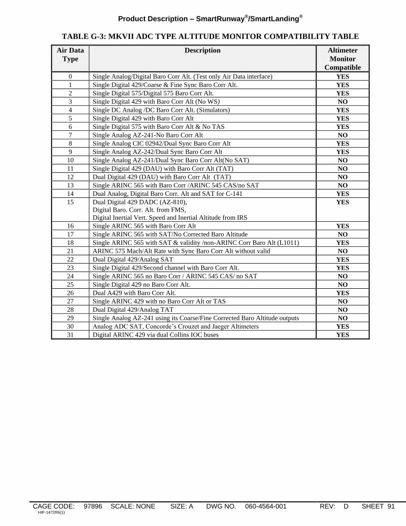
Product Description – SmartRunway®/SmartLanding®
CAGE CODE: 97896 SCALE: NONE SIZE: A DWG NO. 060-4564-001 REV: D SHEET 91 HIF-1472R6(1)
TABLE G-3: MKVII ADC TYPE ALTITUDE MONITOR COMPATIBILITY TABLE
Air Data
Type
Description Altimeter
Monitor
Compatible
0 Single Analog/Digital Baro Corr Alt. (Test only Air Data interface) YES
1 Single Digital 429/Coarse & Fine Sync Baro Corr Alt. YES
2 Single Digital 575/Digital 575 Baro Corr Alt. YES
3 Single Digital 429 with Baro Corr Alt (No WS) NO
4 Single DC Analog /DC Baro Corr Alt. (Simulators) YES
5 Single Digital 429 with Baro Corr Alt YES
6 Single Digital 575 with Baro Corr Alt & No TAS YES
7 Single Analog AZ-241-No Baro Corr Alt NO
8 Single Analog CIC 02942/Dual Sync Baro Corr Alt YES
9 Single Analog AZ-242/Dual Sync Baro Corr Alt YES
10 Single Analog AZ-241/Dual Sync Baro Corr Alt(No SAT) NO
11 Single Digital 429 (DAU) with Baro Corr Alt (TAT) NO
12 Dual Digital 429 (DAU) with Baro Corr Alt (TAT) NO
13 Single ARINC 565 with Baro Corr /ARINC 545 CAS/no SAT NO
14 Dual Analog, Digital Baro Corr. Alt and SAT for C-141 YES
15 Dual Digital 429 DADC (AZ-810),
Digital Baro. Corr. Alt. from FMS,
Digital Inertial Vert. Speed and Inertial Altitude from IRS
YES
16 Single ARINC 565 with Baro Corr Alt YES
17 Single ARINC 565 with SAT/No Corrected Baro Altitude NO
18 Single ARINC 565 with SAT & validity /non-ARINC Corr Baro Alt (L1011) YES
21 ARINC 575 Mach/Alt Rate with Sync Baro Corr Alt without valid NO
22 Dual Digital 429/Analog SAT YES
23 Single Digital 429/Second channel with Baro Corr Alt. YES
24 Single ARINC 565 no Baro Corr / ARINC 545 CAS/ no SAT NO
25 Single Digital 429 no Baro Corr Alt. NO
26 Dual A429 with Baro Corr Alt. YES
27 Single ARINC 429 with no Baro Corr Alt or TAS NO
28 Dual Digital 429/Analog TAT NO
29 Single Analog AZ-241 using its Coarse/Fine Corrected Baro Altitude outputs NO
30 Analog ADC SAT, Concorde‟s Crouzet and Jaeger Altimeters YES
31 Digital ARINC 429 via dual Collins IOC buses YES

Product Description – SmartRunway®/SmartLanding®
CAGE CODE: 97896 SCALE: NONE SIZE: A DWG NO. 060-4564-001 REV: D SHEET 92 HIF-1472R6(1)
Appendix H: Boeing OEM RAAS installation
This appendix describes how the Boeing Service Bulletin for RAAS, and the Boeing factory installation, differs from
a typical STC installation.
The differences can be summarized as follows:
For MKV, An EGPWS program pin is used to enable RAAS along with the RCD.
For MKV-A, the functions described in this document are enabled via the OSS file instead of the RCD.
A RAAS inhibit switch is provided.
Annunciation of the status of RAAS is always provided (via cockpit lamp or EICAS messages).
Visuals, either via raster overlay, or stroke written characters on the NDs, are activated for RAAS cautions.
RAAS Status items: The following conditions can activate flight deck status annunciations:
1: RAAS INOP (inoperative) due to input failures.
2: Aircraft is not program pinned to activate RAAS.
3: Aircraft is program pinned to activate RAAS but there is a problem with the RCD/OSS, no RCD/OSS is present,
or the selected aircraft type is not in the RCD/OSS.
4: Aircraft is approaching, or is at, an airport that is not RAAS qualified.
5: EGPWS power is off.
6: RAAS is manually inhibited.
7: RAAS Inhibit switch unreasonable: Similar to how the Flap & Gear Inhibit switches are monitored, if the RAAS
Inhibit input is selected either intentionally, or via a switch/wiring fault, then once airspeed exceeds 250 knots for 60
seconds the RUNWAY INOP annunciation will come on for non-EICAS aircraft. For EICAS aircraft separate
annunciations are provided for the state of the inhibit switch and the state of the inhibit switch monitor fault.
8: RAAS not functional due to insufficient GPS accuracy.
As the various Boeing models have different display and maintenance message capabilities, the following describes
how the status items are displayed for each model:
737NG
Inhibit Switch A modified Ground Proximity switch panel is provided that adds a “RUNWAY INHIBIT” switch next to
the Terrain, Gear, and Flap Inhibit switches. Like the other switches on this module, it is a guarded switch
with no illumination when selected.
Status An amber “RUNWAY INOP” light is added to the modified Ground Proximity switch panel. This light is
turned on for all of the RAAS status items listed above except #6.
Visuals Amber SHORT RUNWAY and ON TAXIWAY raster text on ND
Note: Provisions are present such that if the 737NG display is updated to provide stroke written visuals
for these messages the raster text will be automatically suppressed.
747-400 - Preliminary
Inhibit Switch A modified Ground Proximity switch panel is provided that adds a “RUNWAY OVRD” switch along
with the Terrain, Gear, and Flap Inhibit switches. White “OVRD” is displayed on the switch when inhibit
is selected.
Status The override switch has an amber “INOP” annunciator built into it to display RAAS Status. This
annunciator is turned on for all the RAAS status items listed above except #6.
Visuals Amber SHORT RUNWAY and ON TAXIWAY raster text on ND
757/767 - Preliminary
Inhibit Switch A RUNWAY OVRD switch is will be added. White “OVRD” is displayed on the switch when inhibit is
selected.
Status The override switch has an amber “INOP” annunciator built into it to display RAAS Status. This
annunciator is turned on for any of the RAAS status items listed above except #6.
Visuals Amber SHORT RUNWAY and ON TAXIWAY raster text on ND

Product Description – SmartRunway®/SmartLanding®
CAGE CODE: 97896 SCALE: NONE SIZE: A DWG NO. 060-4564-001 REV: D SHEET 93 HIF-1472R6(1)
747-8
Inhibit Switch A modified Ground Proximity switch panel is provided that has a “RUNWAY OVRD” switch along with
the Terrain, Gear, and Flap Inhibit switches. There is no „INOP‟ annunciator in the switch. White
“OVRD” is displayed on the switch when inhibit is selected.
Status RAAS status is provided via the following EICAS messages:
Amber RUNWAY SYS: Set for RAAS Status items 1, 3, 4
Amber RUNWAY POS: Set when GPS accuracy insufficient for RAAS
Amber RUNWAY OVRD: Set when Runway Override switch selected
Amber RUNWAY OVERRIDE SWITCH IS FAILED: CMC message for RAAS Status item 7
Visuals Amber SHORT RUNWAY and ON TAXIWAY ND messages
777
Inhibit Switch A RUNWAY OVRD switch is added to the P5 overhead panel. There is no „INOP‟ annunciator in the
switch. White “OVRD” is displayed on the switch when inhibit is selected.
Status Depending on the AIMS version, RAAS status can be provided via the following EICAS messages:
Amber RUNWAY SYS: Set for RAAS Status items 1, 3, 4
Amber RUNWAY POS: Set when GPS accuracy insufficient for RAAS (AIMS 1 only)
Amber RUNWAY OVRD: Set when Runway Override switch selected
Amber RUNWAY OVERRIDE SWITCH IS FAILED: CMC message for RAAS Status item 7
Visuals Amber SHORT RUNWAY and ON TAXIWAY raster text on ND for AIMS Blockpoint BPV14 and
earlier. Note: If the displays provide stroke written visuals for these messages the raster text is
automatically suppressed.
737-300/400/500 - Preliminary
Inhibit Switch Like the 737NG, a modified Ground Proximity switch panel may be provided that has a “RUNWAY
INHIBIT” switch next to the Terrain, Gear, and Flap Inhibit switches. There is some variety among the
various 737 switch configurations, so one inhibit switch installation will not fit all.
Status Depending on the configuration an amber “RUNWAY INOP” light may be added to the modified Ground
Proximity switch panel, or placed adjacent to a separate RUNWAY INHIBIT switch that will turn on for
all RAAS status items listed above except #6.
Visuals Amber SHORT RUNWAY and ON TAXIWAY raster text on ND
717/MD10/MD11 - Preliminary
Inhibit Switch A RUNWAY OVRD switch is added. White “OVRD” is displayed on the switch when inhibit is
selected.
Status The RWY OVRD switch has an amber “INOP” annunciator built into it to display RAAS Status. This
annunciator is turned on for all of the RAAS status items listed above. In addition, the following EAD
(Engine and Alert Display) messages may be added in the future.
Amber RUNWAY FAIL: Set for RAAS Status items 1, 3.
Amber RUNWAY NOT AVAIL: Set for RAAS Status items 4 and 8.
Cyan RUNWAY OVRD: Set when RWY override switch selected.
Visuals Amber SHORT RUNWAY and ON TAXIWAY raster text on ND
Note: ARINC 429outputs are set during these conditions for use if displays are updated to provide RAAS
Caution messages. If that happens, an RCD change would be required to disable the raster messages.
MD8x - Preliminary
Inhibit Switch A RUNWAY OVRD switch is added. White “OVRD” is displayed on the switch when inhibit is selected.
Status The RWY OVRD switch has an amber “INOP” annunciator built into it to display RAAS Status. This
annunciator is turned on for all of the RAAS status items listed above except #5 & #6.
Visuals Amber SHORT RUNWAY and ON TAXIWAY raster text on ND