Embed Size (px)
Citation preview

Product Data SheetOctober 2014
00813-0100-4811, Rev HA
Rosemount 3300 SeriesGuided Wave Radar Level and Interface Transmitter
Accurate, direct level measurement virtually unaffected by process conditions
Minimized maintenance with no moving parts and no re-calibration required
Fewer process penetrations and reduced installation costs with a MultiVariable™ level and interface transmitter
Easy installation and commissioning through two-wire technology and user-friendly configuration
Versatile and easy-to-use transmitter with field proven reliability
High application flexibility with a wide range of process connections, probe styles, and accessories

Rosemount 3300 Series October 2014
Proven, reliable, and easy to use guided wave radar
Measurement principle
Low power, nano-second microwave pulses are guided down a probe submerged in the process media. When a microwave pulse reaches a media with a different dielectric constant, part of the energy is reflected back to the transmitter.
The transmitter uses the residual wave of the first reflection for measuring the interface level. Part of the wave, which was not reflected at the upper product surface, continues until it is reflected at the lower product surface. The speed of this wave depends fully on the dielectric constant of the upper product.
The time difference between the transmitted and the reflected pulse is converted into a distance, and the total level or interface level is then calculated. The reflection intensity depends on the dielectric constant of the product. The higher the dielectric constant value, the stronger the reflection.
Guided wave radar technology benefits
No moving parts and no re-calibration minimizes maintenance
Direct level measurement means no compensation needed for changing process conditions (i.e. density, conductivity, temperature, and pressure)
Handles vapor and turbulence well
Suitable for small tanks, difficult tank geometry, and interfering obstacles
Allows for easy upgrade
Top down installation minimizes risk for leakages
Contents
Ordering Information . . . . . . . . . . . . . . . . . . . . . . . . . . . . . . 5
Specifications. . . . . . . . . . . . . . . . . . . . . . . . . . . . . . . . . . . . 14
Product Certifications . . . . . . . . . . . . . . . . . . . . . . . . . . . . .31
Dimensional Drawings . . . . . . . . . . . . . . . . . . . . . . . . . . . .34
Referencepulse
Level
Interface level
2 www.rosemount.com

Rosemount 3300 SeriesOctober 2014
Special 3300 features
Proven high reliability increases uptime
First 2-wire level and interface transmitter with field proven reliability
More than 90,000 units installed
Advanced signal processing for reliable measurement
Accurate level unaffected by changing process conditions
High application flexibility
Suitable for most liquid storage and monitoring level and interface applications
A wide selection of process connections and probe styles
Remote mounting, mounting bracket, Smart Wireless THUM™ Adapter, HART® Tri-Loop™, and probe centering discs accessories
External mounting using Rosemount 9901 high quality chambers accessories
Robust design reduces costs and increases safety
Leakage prevention and reliable performance under challenging conditions
Detachable transmitter head allows tank to remain sealed
Dual Compartment housing separates cable connections and electronics
Easy installation and plant integration
Seamless system integration with HART, Modbus®, or IEC 62591 (WirelessHART®) with the THUM adapter
Allows for easy swap by matching existing tank connections
Cut-to-fit probes
Long lengths of rigid probes for robust measurements becomes cost-effective and practical to ship, store and install with the segmented probe option (code 4S)
Pre-configured or user-friendly configuration with wizard, autoconnect, dielectric calculator, and on-line help
MultiVariable – measures simultaneously level and interface, resulting in fewer process penetrations and reduces installation and wiring cost
High application flexibility
Electronics and cable connections are located in separate compartments, providing safer handling and improved moisture protection
Modular design for reduced spare parts and easy replacement of the head without opening the tank
Smart Wireless THUM Adapter enables access to online configuration, multi-variable data, and diagnostics
3www.rosemount.com

Rosemount 3300 Series October 2014
Minimized maintenance reduces cost
No mechanical moving parts that require maintenance
User-friendly software provides easy on-line troubleshooting with echo curve tool and logging
Adjustments without opening tank
No re-calibration or compensation needed due to changing process conditions
Easy replacement of old technology and best fit for chambers
Less need for maintenance reduces costs and improves measurement availability
Reliable measurement, independent of density, turbulence, and vibrations
Unaffected by the mechanical configuration of the chamber
Wide range of options to find the best fit in existing chamber or a complete assembly with Rosemount 9901 high quality chambers
Radar Configuration Tool with installation wizard and waveform plot possibilities provides easy configuration and service
From this... to this... in minutes
4 www.rosemount.com

Rosemount 3300 SeriesOctober 2014
Rosemount 3301 and 3302 Level and/or Interface in Liquids Ordering Information
Rosemount 3301 and 3302 Guided Wave Radar Level transmitters are versatile and easy-to-use with field proven measurement capabilities. Characteristics include:
High application flexibility with a wide range of probe styles, process connections, and materials
HART 4-20 mA, Modbus, or IEC 62591 (WirelessHART) with the THUM adapter
Radar Configuration Tool software package included for easy commissioning and troubleshooting
Additional Information
Specifications: page 14Certifications: page 31Dimensional Drawings: page 34
Specification and selection of product materials, options, or components must be made by the purchaser of the equipment.See page 24 for more information on Material Selection.
Table 1. 3301 and 3302 Level and/or Interface in Liquids Ordering InformationThe starred options (★) represent the most common options and should be selected for best delivery. The non-starred offerings are subject
to additional delivery lead time.
Model Product description
3301 Guided Wave Radar Level Transmitter (interface available for fully submerged probe) ★
3302 Guided Wave Radar Level and Interface Transmitter ★
Signal output
H 4-20 mA with HART communication ★
M RS-485 with Modbus communication(1) ★
Housing material
A Polyurethane-covered Aluminum ★
S Stainless Steel, Grade CF8M (ASTM A743)
Conduit / cable threads
1 ½–14 NPT ★
2 M20 x 1.5 adapter ★
Operating temperature and pressure(2) Probe type
S - 15 psig (-1bar) to 580 psig (40 bar) @ 302 °F (150 °C) 3301: All3302: 1A, 2A, 3B, 4A, 4B, and 4S
★
5www.rosemount.com

Rosemount 3300 Series October 2014
Material of construction(3): Process connection / probe
Probe type
1 316L SST (EN 1.4404) 3301: All3302: 1A, 2A, 3B, 4A, 4B, and 4S
★
2 Alloy C-276 (UNS N10276). With plate design if flanged version.
3301: 3A, 3B, and 4A3302: 3B and 4A
3 Alloy 400 (UNS N04400). With plate design if flanged version.
3301: 3A, 3B, 4A, 5A, and 5B3302: 3B and 4A
7 PTFE covered probe and flange. With plate design.
3301: 4A and 5A, Flanged version3302: 4A, Flanged version
8 PTFE covered probe 3301: 4A and 5A3302: 4A
Sealing, o-ring material (consult factory for other o-ring materials)
V Viton® Fluoroelastomer ★
E Ethylene Propylene ★
K Kalrez® 6375 Perfluoroelastomer ★
B Nitrile Butadiene (NBR) ★
Probe type, model 3301 Process connection Probe lengths
3B Coaxial, perforated. For level and interface measurement.
Flange / 1-in., 1½-in., 2-in. Thread
Min.: 1 ft. 4 in. (0.4 m)Max: 19 ft. 8 in. (6 m)
★
4B Rigid Single Lead 0.5 in. (13 mm)(4) Flange / 1-in., 1½-in., 2-in. Thread / Tri-Clamp™
Min.: 1 ft. 4 in. (0.4 m)Max: 19 ft. 8 in. (6.0 m)
★
5A Flexible Single Lead with weight Flange / 1-in., 1½-in., 2-in. Thread / Tri-Clamp
Min.: 3 ft. 4 in. (1 m)Max: 77 ft. (23.5 m)
★
1A Rigid Twin Lead Flange / 1½-in., 2-in. Thread Min.: 1 ft. 4 in. (0.4 m)Max: 9 ft. 10 in. (3 m)
2A Flexible Twin Lead with weight Flange / 1½-in., 2-in. Thread Min.: 3 ft. 4 in. (1 m)Max: 77 ft. (23.5 m)
3A Coaxial (for level measurement) Flange / 1-in., 1½-in., 2-in. Thread
Min.: 1 ft. 4 in. (0.4 m)Max: 19 ft. 8 in. (6 m)
4A Rigid Single Lead 0.3 in. (8 mm) Flange / 1-in., 1½-in., 2-in. Thread / Tri-Clamp
Min.: 1 ft. 4 in. (0.4 m)Max: 9 ft. 10 in. (3 m)
4S Segmented Rigid Single Lead0.5 in. (13 mm)
Flange / 1-in., 1½-in., 2-in. Thread / Tri-Clamp
Min.: 1 ft. 4 in. (0.4 m)Max: 19 ft. 8 in. (6.0 m)
5B Flexible Single Lead with chuck Flange / 1-in., 1½-in., 2-in. Thread / Tri-Clamp
Min.: 3 ft. 4 in. (1 m)Max: 77 ft. (23.5 m)
Probe Type, model 3302 Process connection Probe lengths
3B Coaxial, perforated. For level and interface measurement.
Flange / 1-in., 1½-in., 2-in. Thread
Min.: 1 ft. 4 in. (0.4 m)Max: 19 ft. 8 in. (6 m)
★
4B Rigid Single Lead 0.5 in. (13 mm)(4) Flange / 1-in., 1½-in., 2-in. Thread / Tri-Clamp
Min.: 1 ft. 4 in. (0.4 m)Max: 19 ft. 8 in. (6.0 m)
★
Table 1. 3301 and 3302 Level and/or Interface in Liquids Ordering InformationThe starred options (★) represent the most common options and should be selected for best delivery. The non-starred offerings are subject
to additional delivery lead time.
6 www.rosemount.com

Rosemount 3300 SeriesOctober 2014
1A Rigid Twin Lead Flange / 1½-in., 2-in. Thread Min.: 1 ft. 4 in. (0.4 m)Max: 9 ft. 10 in. (3 m)
2A Flexible Twin Lead with weight Flange / 1½-in., 2-in. Thread Min.: 3 ft. 4 in. (1 m)Max: 77 ft. (23.5 m)
4A Rigid Single Lead 0.3 in. (8 mm) Flange / 1-in., 1½-in., 2-in. Thread / Tri-Clamp
Min.: 1 ft. 4 in. (0.4 m)Max: 9 ft. 10 in. (3 m)
4S Segmented Rigid Single Lead0.5 in. (13 mm)
Flange / 1-in., 1½-in.,2-in. Thread / Tri-Clamp
Min.: 1 ft. 4 in. (0.4 m)Max: 19 ft. 8 in. (6.0 m)
Probe length units
E English (feet, inch) ★
M Metric (meters, centimeters) ★
Total probe length(5) (feet/m)
xx 0 - 77 ft. or 0-23 m ★
Total probe length(5) (inch/cm)
xx 0 - 11 in. or 0-99 cm ★
Process connection - size / type (consult factory for other process connections)
ASME / ANSI flanges(6)(7)
AA 2 in., 150 lb ★
AB 2 in., 300 lb ★
BA 3 in., 150 lb ★
BB 3 in., 300 lb ★
CA 4 in., 150 lb ★
CB 4 in., 300 lb ★
DA 6 in., 150 lb
EN (DIN) flanges(6)(7)
HB DN50, PN40 ★
IA DN80, PN16 ★
IB DN80, PN40 ★
JA DN100, PN16 ★
JB DN100, PN40 ★
KA DN150, PN16
JIS flanges(6)(7)
UA 50A, 10K ★
VA 80A, 10K ★
XA 100A, 10K ★
UB 50A, 20K
Table 1. 3301 and 3302 Level and/or Interface in Liquids Ordering InformationThe starred options (★) represent the most common options and should be selected for best delivery. The non-starred offerings are subject
to additional delivery lead time.
7www.rosemount.com

Rosemount 3300 Series October 2014
VB 80A, 20K
XB 100A, 20K
YA 150A, 10K
YB 150A, 20K
ZA 200A, 10K
ZB 200A, 20K
Threaded connections(6) Probe type
RA 1½-in. NPT thread 3301: All3302: 1A, 2A, 3B, 4A, 4B, and 4S
★
RC 2-in. NPT thread 3301: 1A, 2A, 3A, 3B, 4A, 4B, 4S, 5A, and 5B3302: 1A, 2A, 3B, 4A, 4B, and 4S
★
RB 1-in. NPT thread 3301: 3A, 3B, 4A, 4B, 4S, 5A, and 5B3302: 3B, 4A, 4B, and 4S
SA 1½-in. BSP (G 1½-in.) thread 3301: All3302: 1A, 2A, 3B, 4A, 4B, and 4S
SB 1-in. BSP (G 1-in.) thread 3301: 3A, 3B, 4A, 4B, 4S, 5A, and 5B3302: 3B, 4A, 4B, and 4S
Tri-Clamp fittings(6) Probe type
FT 1½-in. Tri-Clamp 3301: 4A, 4B, 4S, 5A, and 5B3302: 4A, 4B, and 4S
AT 2-in. Tri-Clamp 3301: 4A, 4B, 4S, 5A, and 5B3302: 4A, 4B, and 4S
BT 3-in. Tri-Clamp 3301: 4A, 4B, 4S, 5A, and 5B3302: 4A, 4B, and 4S
CT 4-in. Tri-Clamp 3301: 4A, 4B, 4S, 5A, and 5B3302: 4A, 4B, and 4S
Proprietary flanges(8)
TF Fisher - proprietary 316L SST (for 249B, 259B cages) Torque Tube Flange ★
TT Fisher - proprietary 316L SST (for 249C cages) Torque Tube Flange ★
TM Masoneilan - proprietary 316L SST Torque Tube Flange ★
Hazardous locations certifications
NA No Hazardous Locations Certifications ★
E1 ATEX Flameproof(9) ★
E3 NEPSI Flameproof(9) ★
E4 TIIS Flameproof(9) ★
E5 FM Explosion-proof(9) ★
E6 CSA Explosion-proof(9) ★
Table 1. 3301 and 3302 Level and/or Interface in Liquids Ordering InformationThe starred options (★) represent the most common options and should be selected for best delivery. The non-starred offerings are subject
to additional delivery lead time.
8 www.rosemount.com

Rosemount 3300 SeriesOctober 2014
E7 IECEx Flameproof(9) ★
I1 ATEX Intrinsic Safety ★
I3 NEPSI Intrinsic Safety ★
I5 FM Intrinsic Safety and Non-Incendive ★
I6 CSA Intrinsic Safety and Non-Incendive ★
I7 IECEx Intrinsic Safety ★
EM Technical Regulations Customs Union (EAC) Flameproof (consult factory for details)
IM Technical Regulations Customs Union (EAC) Intrinsic Safety (consult factory for details)
KA ATEX and CSA Flameproof/Explosion-proof(9)
KB FM and CSA Explosion-proof(9)
KC ATEX and FM Flameproof/Explosion-proof(9)
KD ATEX and CSA Intrinsic Safety
KE FM and CSA Intrinsic Safety
KF ATEX and FM Intrinsic Safety
Options
Display
M1 Integral digital display ★
Hydrostatic testing
P1 Hydrostatic testing(10) ★
Materials Certification
N2 NACE material recommendation per MR-0175(11), MR-0103 ★
Installation options
LS Long stud(12) 9.8 in (250 mm) for flexible single lead probe to prevent contact with wall/nozzle.Standard height is 3.9 in (100 mm)
★
BR Mounting Bracket for 1½-in. NPT Process Connection (RA)
Weight options for flexible single lead probe (5A)
W3 Heavy weight (recommended choice for most applications)Weight=2.43 lb (1.10 kg), Length=5.5 in. (140 mm), Diameter=1.5 in. (37.5 mm)
★
W2 Short weight (when measuring close to the probe end)(13)
Weight=0.88 lb (0.40 kg. Length=2 in. (50 mm), Diameter=1.5 in. (37.5 mm)
Sx and Px - centering discs Outer diameter
S2 2-in. Centering disc(14) 1.8 in. (45 mm) ★
S3 3-in. Centering disc(14) 2.7 in. (68 mm) ★
S4 4-in. Centering disc(14) 3.6 in. (92 mm) ★
P2 2-in. Centering disc PTFE(15) 1.8 in. (45 mm) ★
Table 1. 3301 and 3302 Level and/or Interface in Liquids Ordering InformationThe starred options (★) represent the most common options and should be selected for best delivery. The non-starred offerings are subject
to additional delivery lead time.
9www.rosemount.com

Rosemount 3300 Series October 2014
P3 3-in. Centering disc PTFE(15) 2.7 in. (68 mm) ★
P4 4-in. Centering disc PTFE(15) 3.6 in. (92 mm) ★
S6 6-in. Centering disc(14) 5.55 in. (141 mm)
S8 8-in. Centering disc(14) 7.40 in. (188 mm)
P6 6-in. Centering disc PTFE(15) 5.55 in. (141 mm)
P8 8-in. Centering disc PTFE(15) 7.40 in. (188 mm)
Remote housing(16)
B1 1 m / 3.2 ft. Remote Housing Mounting Cable and Bracket
B2 2 m / 6.5 ft. Remote Housing Mounting Cable and Bracket
B3 3 m / 9.8 ft. Remote Housing Mounting Cable and Bracket
Cx - special configuration (software)
C1 Factory configuration (Configuration Data Sheet required with order, available at www.rosemount.com) ★
C4 Namur alarm and saturation levels, high alarm ★
C5 Namur alarm and saturation levels, low alarm ★
C8 Low alarm(17) (standard Rosemount alarm and saturation levels) ★
Qx - special certs
Q4 Calibration Data Certification ★
Q8 Material Traceability Certification per EN 10204 3.1(18) ★
U1 WHG Overfill Approval. Only available with HART 4-20 mA output (output code H) ★
QG GOST Primary Verification Certificate
Consolidate to chamber
XC Consolidate to Chamber(19)
Engineered solutions (see page 27)
Rxxx Engineered Solutions beyond standard model codes. (Consult factory for details)
(1) Requires external 8-30 Vdc power supply.
(2) Process seal rating. Final rating depends on flange and O-ring selection. See “Process temperature and pressure rating” on page 18”.
(3) For other materials, consult the factory.
(4) Available in SST. Consult the factory for other materials.
(5) Probe weight included if applicable. Give the total probe length in feet and inches or meters and centimeters, depending on selected probe length unit. If tank height is unknown, please round up to an even length when ordering. Probes can be cut to exact length in field. Maximum allowable length is determined by process conditions.
(6) Available in material 316L and EN 1.4404. For other materials consult the factory.
(7) ASME/ANSI: Raised face type for SST flanges. EN: Type A flat face for SST flanges. JIS: Raised face type for SST flanges.
(8) Available in material 316L. For pressure and temperature rating, see page 18.
Table 1. 3301 and 3302 Level and/or Interface in Liquids Ordering InformationThe starred options (★) represent the most common options and should be selected for best delivery. The non-starred offerings are subject
to additional delivery lead time.
10 www.rosemount.com

Rosemount 3300 SeriesOctober 2014
(9) Probes are intrinsically safe.
(10) Available for flanged connection.
(11) 3301: valid for probe type 3A, 3B, 4A, 4B, and 4S. 3302: valid for probe type 3B, 4A, 4B, and 4S.
(12) Not available with PTFE covered probes.
(13) Only for Material of Construction code 1 and Probe Type 5A.
(14) Material in accordance with selected material of construction for probe types 2A, 4A, 4B, 4S, and 5A.
(15) Available for SST, Alloy C-276, and Alloy 400 probes, type 2A, 4A, 4B, 4S, and 5A.
(16) Requires software version 10 or higher
(17) The standard alarm setting is high.
(18) Option available for pressure retaining wetted parts.
(19) Selecting the XC option code on the 3300 Guided Wave Radar and the 9901 Chamber will result in matching, consolidating, configuring, and shipping of the two products in one crate. Note that the flange bolts are only hand-tightened. Long rigid single lead probes (>8 ft/2.5 m) are shipped separately in order to reduce transportation risk damage.
11www.rosemount.com

Rosemount 3300 Series October 2014
Rosemount 3301 and 3302 Accessories
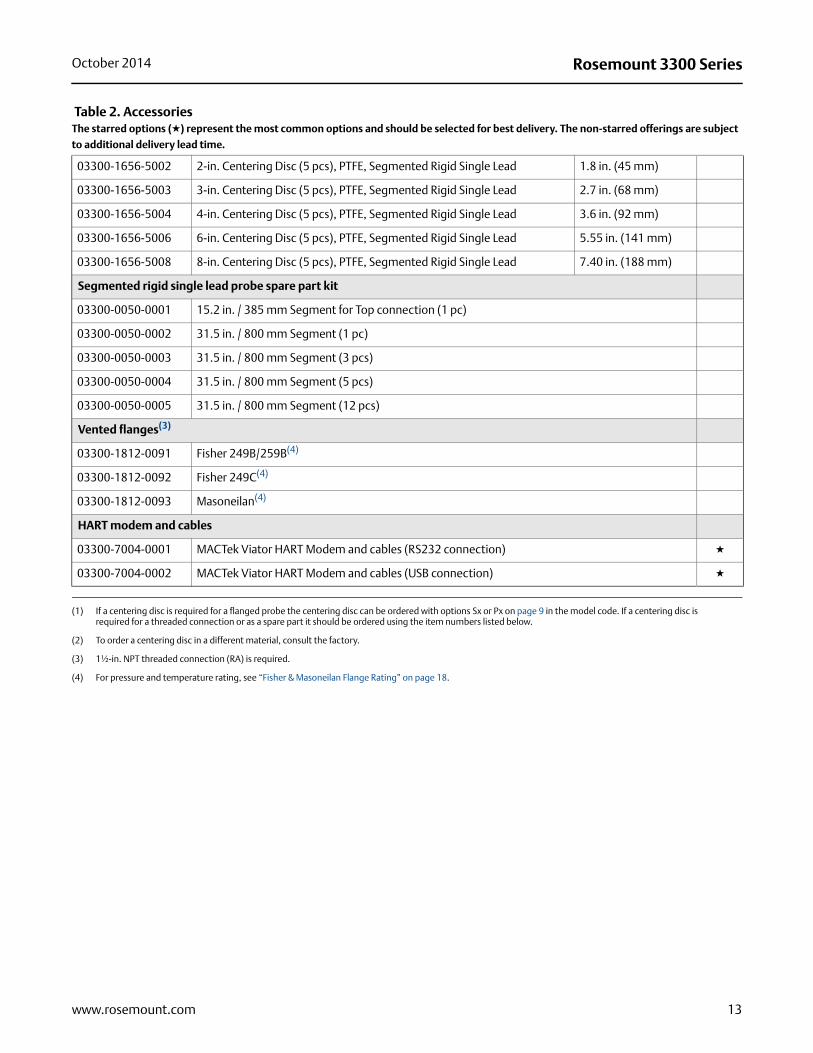
Table 2. AccessoriesThe starred options (★) represent the most common options and should be selected for best delivery. The non-starred offerings are subject
to additional delivery lead time.
Centering discs(1)(2) Outer diameter
03300-1655-0001 Kit, 2-in. Centering Disc, SST, Rigid Single 1.8 in. (45 mm) ★
03300-1655-0002 Kit, 3-in. Centering Disc, SST, Rigid Single 2.7 in. (68 mm) ★
03300-1655-0003 Kit, 4-in. Centering Disc, SST, Rigid Single 3.6 in. (92 mm) ★
03300-1655-0006 Kit, 2-in. Centering Disc, PTFE, Rigid Single 1.8 in. (45 mm) ★
03300-1655-0007 Kit, 3-in. Centering Disc, PTFE, Rigid Single 2.7 in. (68 mm) ★
03300-1655-0008 Kit, 4-in. Centering Disc, PTFE, Rigid Single 3.6 in. (92 mm) ★
03300-1655-1001 Kit, 2-in. Centering Disc, SST, Single / Twin Flex Lead 1.8 in. (45 mm) ★
03300-1655-1002 Kit, 3-in. Centering Disc, SST, Single / Twin Flex Lead 2.7 in. (68 mm) ★
03300-1655-1003 Kit, 4-in. Centering Disc, SST, Single / Twin Flex Lead 3.6 in. (92 mm) ★
03300-1655-1006 Kit, 2-in. Centering Disc, PTFE, Single / Twin Flex Lead 1.8 in. (45 mm) ★
03300-1655-1007 Kit, 3-in. Centering Disc, PTFE, Single / Twin Flex Lead 2.7 in. (68 mm) ★
03300-1655-1008 Kit, 4-in. Centering Disc, PTFE, Single / Twin Flex Lead 3.6 in. (92 mm) ★
03300-1655-0004 Kit, 6-in. Centering Disc, SST, Rigid Single 5.55 in. (141 mm)
03300-1655-0005 Kit, 8-in. Centering Disc, SST, Rigid Single 7.40 in. (188 mm)
03300-1655-0009 Kit, 6-in. Centering Disc, PTFE, Rigid Single 5.55 in. (141 mm)
03300-1655-0010 Kit, 8-in. Centering Disc, PTFE, Rigid Single 7.40 in. (188 mm)
03300-1655-1004 Kit, 6-in. Centering Disc, SST, Single / Twin Flex Lead 5.55 in. (141 mm)
03300-1655-1005 Kit, 8-in. Centering Disc, SST, Single / Twin Flex Lead 7.40 in. (188 mm)
03300-1655-1009 Kit, 6-in. Centering Disc, PTFE, Single / Twin Flex Lead 5.55 in. (141 mm)
03300-1655-1010 Kit, 8-in. Centering Disc, PTFE, Single / Twin Flex Lead 7.40 in. (188 mm)
Centering discs for mounting between segments (probe type 4S only) Outer diameter
03300-1656-1002 2-in. Centering Disc (1 pc), PTFE, Segmented Rigid Single Lead 1.8 in. (45 mm)
03300-1656-1003 3-in. Centering Disc (1 pc), PTFE, Segmented Rigid Single Lead 2.7 in. (68 mm)
03300-1656-1004 4-in. Centering Disc (1 pc), PTFE, Segmented Rigid Single Lead 3.6 in. (92 mm)
03300-1656-1006 6-in. Centering Disc (1 pc), PTFE, Segmented Rigid Single Lead 5.55 in. (141 mm)
03300-1656-1008 8-in. Centering Disc (1 pc), PTFE, Segmented Rigid Single Lead 7.40 in. (188 mm)
03300-1656-3002 2-in. Centering Disc (3 pcs), PTFE, Segmented Rigid Single Lead 1.8 in. (45 mm)
03300-1656-3003 3-in. Centering Disc (3 pcs), PTFE, Segmented Rigid Single Lead 2.7 in. (68 mm)
03300-1656-3004 4-in. Centering Disc (3 pcs), PTFE, Segmented Rigid Single Lead 3.6 in. (92 mm)
03300-1656-3006 6-in. Centering Disc (3 pcs), PTFE, Segmented Rigid Single Lead 5.55 in. (141 mm)
03300-1656-3008 8-in. Centering Disc (3 pcs), PTFE, Segmented Rigid Single Lead 7.40 in. (188 mm)
12 www.rosemount.com
Rosemount 3300 SeriesOctober 2014
03300-1656-5002 2-in. Centering Disc (5 pcs), PTFE, Segmented Rigid Single Lead 1.8 in. (45 mm)
03300-1656-5003 3-in. Centering Disc (5 pcs), PTFE, Segmented Rigid Single Lead 2.7 in. (68 mm)
03300-1656-5004 4-in. Centering Disc (5 pcs), PTFE, Segmented Rigid Single Lead 3.6 in. (92 mm)
03300-1656-5006 6-in. Centering Disc (5 pcs), PTFE, Segmented Rigid Single Lead 5.55 in. (141 mm)
03300-1656-5008 8-in. Centering Disc (5 pcs), PTFE, Segmented Rigid Single Lead 7.40 in. (188 mm)
Segmented rigid single lead probe spare part kit
03300-0050-0001 15.2 in. / 385 mm Segment for Top connection (1 pc)
03300-0050-0002 31.5 in. / 800 mm Segment (1 pc)
03300-0050-0003 31.5 in. / 800 mm Segment (3 pcs)
03300-0050-0004 31.5 in. / 800 mm Segment (5 pcs)
03300-0050-0005 31.5 in. / 800 mm Segment (12 pcs)
Vented flanges(3)
03300-1812-0091 Fisher 249B/259B(4)
03300-1812-0092 Fisher 249C(4)
03300-1812-0093 Masoneilan(4)
HART modem and cables
03300-7004-0001 MACTek Viator HART Modem and cables (RS232 connection) ★
03300-7004-0002 MACTek Viator HART Modem and cables (USB connection) ★
(1) If a centering disc is required for a flanged probe the centering disc can be ordered with options Sx or Px on page 9 in the model code. If a centering disc is required for a threaded connection or as a spare part it should be ordered using the item numbers listed below.
(2) To order a centering disc in a different material, consult the factory.
(3) 1½-in. NPT threaded connection (RA) is required.
(4) For pressure and temperature rating, see “Fisher & Masoneilan Flange Rating” on page 18.
Table 2. AccessoriesThe starred options (★) represent the most common options and should be selected for best delivery. The non-starred offerings are subject
to additional delivery lead time.
13www.rosemount.com

Rosemount 3300 Series October 2014
Specifications
Functional specifications
General
Field of Application
Liquids and semi-liquids level or liquid/liquid interfaces
Model 3301, for level or submerged probe interface measurement Model 3302, for level and interface measurements
Measurement Principle Time Domain Reflectometry (TDR). (See “Measurement principle” on page 2 for a description of how it works)
Microwave Output Power Nominal 50 W, Max. 2 mW
Telecommunication(FCC and R&TTE)
FCC part 15 (1998) subpart B and R&TTE (EU directive 99/5/EC). The 3300 Series is considered to be an unintentional radiator under the Part 15 rules
Humidity 0 to 100% relative humidity
Start-up time < 10 s
4–20 mA HART (output option code H) – (see signal output in Table 1 on page 5)
Output
Two-wire, 4–20 mA. Digital process variable is superimposed on 4–20 mA signal, and available to any host that conforms to the HART protocol (HART rev. 5). The HART signal can be used in a multidrop mode.
HART Tri-Loop
By sending the digital HART signal to the optional HART Tri-Loop, it is possible to have up to three additional 4–20 mA analog signals. See the Rosemount 333 HART Tri-Loop Product Data Sheet (document number 00813-0100-4754) for additional information.
Smart Wireless THUM Adapter
The optional THUM adapter can be mounted directly on the transmitter or by using a remote mounting kit. IEC 62591 (WirelessHART) enables access to multi-variable data and diagnostics, and adds wireless to almost any measurement point. See the Rosemount Smart Wireless THUM adapter Product Data Sheet (document number 00813-0100-4075) and Smart Wireless THUM Adapter for Rosemount Process Level Transmitter Applications (document number 00840-0100-4026).
Rosemount 3300 Series Transmitter
Rosemount 751 Field Signal Indicator
4-20 mA / HART
475 Field Communicator
Radar Configuration Tools or AMS Device Manager
Rosemount 333 HART Tri-Loop
3 x 4–20 mA
Control System
HART
Modem
14 www.rosemount.com

Rosemount 3300 SeriesOctober 2014
External Power Supply
The input voltage (Ui) for HART is 11 to 42 Vdc(11 to 30 Vdc in IS applications, and 16 to 42 Vdc in Explosion-proof/Flameproof applications).
For Flameproof/Explosion-proof installations the Rosemount 3300 Series transmitters have a built-in barrier; no external barrier needed.
When a Smart Wireless THUM adapter is fitted, it adds a maximum drop of 2.5 Vdc in the connected loop.
R = Load Resistance (); UE = External Power Supply Voltage (Vdc); and UI = Input Voltage (Vdc)
IS Electrical Parameters Ui = 30 V, li = 130 mA, Pi = 1 W, Li = 0, Ci = 0
Signal on Alarm Standard: Low = 3.75 mA. High = 21.75 mA; Namur NE43: Low = 3.6 mA. High = 22.5 mA
Saturation Levels Standard: Low = 3.9 mA. High=20.8 mA; Namur NE43: Low = 3.8 mA. High = 20.5 mA
Load Limitations
Maximum load resistance is determined by the voltage level of the external power supply, as described by:
R UE
UI
11
400
800
1200
1600
20 30 40 50
4224
650
1550
400
800
1200
1600
11 20 30 40 50
950
650
24
R ()
UE (V)
R ()
UE (V)
Operating Region
UE =External Power Supply Voltage; R () = Maximum Load Resistance
11 20 30 40 50
400
800
1200
1600
1300
16 24 42UE (V)
R ()
Operating Region
Non-Hazardous Installations Intrinsically Safe Installations
Explosion-proof/Flameproof (Ex d) Installations
NoteFor the Ex d case, the diagram is only valid if the HART load resistance is at the + side, otherwise the load resistance value is limited to 300
15www.rosemount.com
Rosemount 3300 Series October 2014
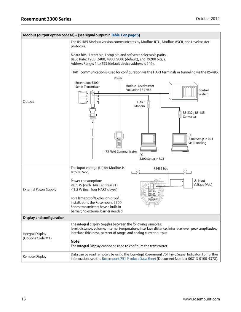
Modbus (output option code M) – (see signal output in Table 1 on page 5)
Output
The RS-485 Modbus version communicates by Modbus RTU, Modbus ASCII, and Levelmaster protocols.
8 data bits, 1 start bit, 1 stop bit, and software selectable parity.Baud Rate: 1200, 2400, 4800, 9600 (default), and 19200 bits/s.Address Range: 1 to 255 (default device address is 246).
HART communication is used for configuration via the HART terminals or tunneling via the RS-485.
External Power Supply
The input voltage (UI) for Modbus is8 to 30 Vdc.
Power consumption:< 0.5 W (with HART address=1)< 1.2 W (incl. four HART slaves)
For Flameproof/Explosion-proof installations the Rosemount 3300 Series transmitters have a built-in barrier; no external barrier needed.
Display and configuration
Integral Display(Options Code M1)
The integral display toggles between the following variables: level, distance, volume, internal temperature, interface distance, interface level, peak amplitudes,interface thickness, percent of range, and analog current output
Note The Integral Display cannot be used to configure the transmitter.
Remote DisplayData can be read remotely by using the four-digit Rosemount 751 Field Signal Indicator. For further information, see the Rosemount 751 Product Data Sheet (Document Number 00813-0100-4378).
Rosemount 3300 Series Transmitter
Control System
HARTModem
PC 3300 Setup in RCT via Tunneling
Power
475 Field Communicator
Modbus, Levelmaster Emulation / RS-485
PC3300 Setup in RCT
RS-232 / RS-485Converter
RS485 bus
UI: Input Voltage (Vdc)
16 www.rosemount.com

Rosemount 3300 SeriesOctober 2014
Configuration Tools(See earlier “Output” diagrams)
Emerson Field Communicator (e.g. 375/475 Field Communicator), Radar Configuration Tools (RCT) software package for PC (included with delivery of transmitter), orEmerson AMS® Device Manager for PC, or DeltaV™ or any other DD (Device Description) compatible host systems.
Note DTM™ (compliant with version 1.2 of the FDT®/DTM specification) is also available supporting
configuration in for instance Yokogawa® Fieldmate/PRM, E+H™ FieldCare, and PactWare™. To communicate using RCT or AMS Device Manager, a HART modem is required. The HART
modem is available as an RS232 or USB version (see “Rosemount 3301 and 3302 Accessories” on page 12).
The transmitter can be pre-configured by selecting option code C1 (see page 10) and sending a completed Configuration Data Sheet (CDS). The CDS is available from www.rosemount.com.
Output UnitsFor Level, Interface, and Distance: ft, inch, m, cm, or mmFor Volume: ft3, inch3, US gals, Imp gals, barrels, yd3, m3, or liters
Output Variables
Model 3301: Level, Distance (to product surface), Volume, Internal Temperature, and Peak Amplitudes. (For submerged probe interface measurements: Interface Level and Interface Distance)Model 3302: Level, Distance (to product surface), Volume, Interface Level, Interface Distance, Upper Product Thickness, Internal Temperature, and Peak Amplitudes
Damping 0 to 60 s (10 s is the default value)
Temperature limits
Ambient Temperature
The maximum and minimum ambient temperature for the electronics depends on the process temperature and on the approval (see “Product Certifications” on page 31).
The temperature range for the optional Integral Display is –40 °F (–40 °C) to 185 °F (85 °C). To lower the temperature around the electronics, a Remote Mounting Connection can be used.
The maximum temperature for the Remote Housing Connection at the vessel connection point is 302 °F (150 °C).
Storage Temperature –40 to 176 °F (–40 to 80 °C)
17www.rosemount.com
Rosemount 3300 Series October 2014
Process temperature and pressure rating
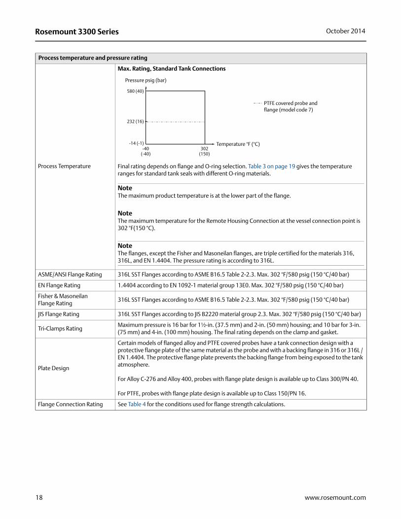
Process Temperature
Max. Rating, Standard Tank Connections
Final rating depends on flange and O-ring selection. Table 3 on page 19 gives the temperature ranges for standard tank seals with different O-ring materials.
NoteThe maximum product temperature is at the lower part of the flange.
NoteThe maximum temperature for the Remote Housing Connection at the vessel connection point is 302 °F(150 °C).
NoteThe flanges, except the Fisher and Masoneilan flanges, are triple certified for the materials 316, 316L, and EN 1.4404. The pressure rating is according to 316L.
ASME/ANSI Flange Rating 316L SST Flanges according to ASME B16.5 Table 2-2.3. Max. 302 °F/580 psig (150 °C/40 bar)
EN Flange Rating 1.4404 according to EN 1092-1 material group 13E0. Max. 302 °F/580 psig (150 °C/40 bar)
Fisher & Masoneilan Flange Rating
316L SST Flanges according to ASME B16.5 Table 2-2.3. Max. 302 °F/580 psig (150 °C/40 bar)
JIS Flange Rating 316L SST Flanges according to JIS B2220 material group 2.3. Max. 302 °F/580 psig (150 °C/40 bar)
Tri-Clamps RatingMaximum pressure is 16 bar for 1½-in. (37.5 mm) and 2-in. (50 mm) housing; and 10 bar for 3-in. (75 mm) and 4-in. (100 mm) housing. The final rating depends on the clamp and gasket.
Plate Design
Certain models of flanged alloy and PTFE covered probes have a tank connection design with a protective flange plate of the same material as the probe and with a backing flange in 316 or 316L / EN 1.4404. The protective flange plate prevents the backing flange from being exposed to the tank atmosphere.
For Alloy C-276 and Alloy 400, probes with flange plate design is available up to Class 300/PN 40.
For PTFE, probes with flange plate design is available up to Class 150/PN 16.
Flange Connection Rating See Table 4 for the conditions used for flange strength calculations.
Pressure psig (bar)
580 (40)
232 (16)
-14 (-1)-40
(-40)302
(150)
Temperature °F (°C)
PTFE covered probe and flange (model code 7)
18 www.rosemount.com

Rosemount 3300 SeriesOctober 2014
Table 3. Temperature Ranges for Standard Tank Seals with Different O-ring Materials
NoteAlways check the chemical compatibility of the o-ring material with your application.
Interface Measurements
Considerations
The Rosemount 3302 is a good choice for measuring the interface of oil and water, or other liquids with significant dielectric differences. It is also possible to measure interfaces with a Rosemount 3301 in applications where the probe is fully submerged in the liquid. If interface is to be measured, follow these criteria:
The dielectric constant of the upper product must be known and should not vary. The Radar Configuration Tools software has a built-in dielectric constant calculator to assist the user in determining the dielectric constant of the upper product.
The dielectric constant of the upper product must have a lower dielectric constant than the lower product to have a distinct reflection.
The difference between the dielectric constants for the two products must be larger than 10. Max. dielectric constant for the upper product is 10 for the coaxial probe and 5 for twin lead
probes. The upper product thickness must be larger than 8 in. (0.2 m) for the flexible twin lead probe;
4 in. (0.1 m) for the rigid twin lead, and coaxial probes in order to distinguish the echoes of the two liquids.
Sometimes there is an emulsion layer (mix of the products) between the two products which can affect interface measurements. For guidelines on emulsion situations, consult your local Emerson Process Management representative.
Tank seal with different O-ring material Min. temperature °F (°C) in air Max. temperature °F (°C) in air
Viton Fluoroelastomer 5 (-15) 302 (150)
Ethylene Propylene (EPDM) -40 (-40) 266 (130)
Kalrez 6375 Perfluoroelastomer 14 (-10) 302 (150)
Nitrile Butadiene (NBR) -31 (-35) 230 (110)
Interface Measurement with a Rosemount 3302 and a Rosemount 3301 (fully submerged probe)
3302 3301
Product level
Interface level
Interface level
Table 4. Conditions Used for Flange Strength Calculations
Bolting material Gasket Flange material Hub material
ASME / ANSISST SA193 B8M Class 2
Soft (1a) with min. thickness 1.6 mm SST A182
Gr. F316L and EN 10222-5-1.4404
SST SA479M 316L and EN 10272-1.4404
EN, JISEN 1515-1/-2 group 13E0, A4-70
Soft (EN 1514-1) with min. thickness 1.6 mm
19www.rosemount.com

Rosemount 3300 Series October 2014
Performance specifications
General
Reference Conditions Twin Lead probe, 77 °F (25 °C) water
Reference Accuracy± 0.2 in. (5 mm) for probes 16.4 ft. (5 m)± 0.1% of measured distance for rigid probes >16.4 ft. (5 m)± 0.15% of measured distance for flexible probes >16.4 ft. (5 m)
Repeatability ± 0.04 in. (1 mm)
Ambient Temperature Effect Less than 0.01% of measured distance per °C
Update Interval 1 per second
Measuring range
Transition Zones
These zones are areas where measurements are non-linear or have reduced accuracy. If measurements are desired at the very top of a tank, it is possible to mechanically extend the nozzle and use a coaxial probe. The upper transition zone is then moved into the extension. See Table 5 on page 22.
Measuring Range and Minimum Dielectric Constant
16 in. (0.4 m) to 77 ft. (23.5 m)
See Table 6 on page 22 for each probe’s measuring range and minimum dielectric constant. Due to the measuring range depending on the application and factors described below, the values are a guideline for clean liquids. For more information, ask your local Emerson Process Management representative.
Different parameters (factors) affect the echo and therefore the maximum measuring range differs depending on application according to:
Disturbing objects close to the probe Media with higher dielectric constants (r) give better reflection and allow a longer measuring
range Surface foam and particles in the tank atmosphere may affect measuring performance Heavy coating or contamination on the probe should be avoided since it can reduce measuring
range and might cause erroneous level readings
NoteSee Table 7 on page 23 for the measuring range when using the Remote Housing.
Upper Reference Point
Upper Transition Zone
Maximum Recommended Measuring Range
Lower Transition Zone
Lower Reference Point
Lower Transition ZoneFor a flexible single lead probe with chuck, the lower transition zone is measured upwards from the upper part of the clamp.
Lower Transition Zone
20 www.rosemount.com

Rosemount 3300 SeriesOctober 2014
Interface Measuring Range
Target applications include interfaces between oil; oil-like and water; and water-like liquids with a low (<3) upper product dielectric constant and a high (>20) lower product dielectric constant. For such applications, the max measuring range is only limited by the length of the coaxial, rigid twin and rigid single lead probes.
For the flexible twin lead probe, the maximum measuring range will be reduced depending on the maximum upper product thickness according to the diagram.
Example: If the Upper Product Dielectric Constant is 2, and the Upper Product Thickness is 5 ft.(1.5 m), the Maximum Measuring Range is 75.5 ft. (23 m).
However, characteristics vary between different applications. For other product combinations, consult your local Emerson Process Management representative.
Environment
Vibration Resistance Polyurethane-covered aluminum housing: IEC 60770-1. SST housing: IACS E10
Electromagnetic Compatibility
Emission and Immunity: meets EN 61326-1 (2006) and amendment A1, class A equipmentintended for use in industrial locations if installed in metallic vessels or still-pipes.When rigid/flexible single and twin lead probes are installed in non-metallic or open vessels,influence of strong electromagnetic fields might affect measurements.
Built-in Lightning Protection Meets EN 61000-4-4 Severity Level 4 and EN 61000-4-5 Severity Level 4
Coating(See Table 8 on page 23)
Single lead probes are preferred when there is a risk for contamination (because coating can result in product bridging across the two leads for twin versions; between the inner lead and outer pipe for the coaxial probe).
PTFE probes are recommended for viscous or sticky applications. Periodic cleaning might be required.
For viscous or sticky applications, it is not recommended to use centering discs mounted along the probe.
Maximum error due to coating is 1 to 10% depending on probe type, dielectric constant, coating thickness, and coating height above product surface.
CE-mark The 4–20 mA HART version (Output Option Code H) complies with applicable directives (EMC and ATEX).
0 (0) 3.3 (1)65.6 (20)
68.9 (21)
72.2 (22)
75.5 (23)
78.7 (24)
82.0 (25)
2
3
5
6.6 (2) 9.8 (3) 13.1 (4) 16.4 (5)
Maximum Measuring Range, Flexible Twin Lead Probe, ft. (m)
Upper Product Dielectric Constant
Max Upper Product Thickness, ft. (m)
21www.rosemount.com

Rosemount 3300 Series October 2014
Table 5. Transition Zones
NoteThe 4–20 mA set points are recommended to be configured between the transition zones, within the measuring range.
Table 6. Measuring Range and Minimum Dielectric Constant
Dielectric constant
Rigid single lead/segmented rigid single lead
Flexible single lead Coaxial Rigid twin lead Flexible twin lead
Upper(1)
Transition Zone
(1) The distance from the upper reference point where measurements have reduced accuracy.
80 4 in. (10 cm) 5.9 in. (15 cm) 4 in. (10 cm) 4 in. (10 cm) 5.9 in. (15 cm)
2 4 in. (10 cm) 20 in. (50 cm) 4 in. (10 cm) 4 in. (10 cm) 8 in. (20 cm)
Lower(2)
Transition Zone
(2) The distance from the lower reference point where measurements have reduced accuracy.
80 2 in. (5 cm) 2 in. (5 cm)(3)(4)
(3) The measuring range for the PTFE covered Flexible Single Lead probe includes the weight when measuring on a high dielectric media.
1.2 in. (3 cm) 2 in. (5 cm) 2 in. (5 cm)(4)
(4) Note that the weight length or chuck fastening length adds to non-measurable area and is not included in the diagram. See “Dimensional Drawings” on page 37.
2 4 in. (10 cm)(5)
(5) When using a metallic centering disc, the lower transition zone is 8 in. (20 cm), including weight if applicable. When using a PTFE centering disc, the lower transition zone is not affected.
6.3 in. (16 cm) - long weight, short weight, and chuck(4)(5)
2 in. (5 cm) 2.8 in. (7 cm) 5.9 in. (15 cm)(4)(5)
Rigid single lead/segmented rigid single lead
Flexible single lead CoaxialRigid twin lead
flexible twin lead
Maximum measuring range
9 ft 10 in. (3 m) for 8 mm probes(code 4A)
19 ft. 8 in. (6.0 m)for 13 mm probes(code 4B)
19 ft. 8 in. (6.0 m)for 13 mm probes(code 4S)
77 ft 1 in. (23.5 m) 19 ft 8 in. (6 m) 9 ft 10 in. (3 m) 77 ft 1 in. (23.5 m)
Minimum dielectric constant
2.5 (or 1.7 if installed in a metallic bypass or stilling well)(1)
(1) May be lower depending on installation.
2.5 up to 36 ft (11 m)(2)
5.0 up to 66 ft (20 m)7.5 up to 77 ft 1 in. (23.5 m)
(2) In pipes with a diameter less than 8 in. (20 cm), the minimum dielectric constant is 2.0.
1.5 1.91.6 up to 33 ft (10 m)2.0 up to 66 ft (20 m)2.4 up to 77 ft 1 in. (23.5 m)
22 www.rosemount.com

Rosemount 3300 SeriesOctober 2014
Table 7. Measuring Range and Minimum Dielectric Constant when using Remote Housing
Table 8. Maximum Recommended Viscosity and Coating / Build-up
Rigid single lead/Segmented rigid single lead
Flexible single lead Coaxial Rigid twin lead Flexible twin lead
Maximum measuring range
9 ft. 10 in. (3 m) - for 8 mm probes14 ft. 9 in. (4.5 m) - for 13 mm probes
77 ft. 1 in. (23.5 m) 19 ft. 8 in. (6 m) 9 ft. 10 in. (3 m) 77 ft. 1 in. (23.5 m)
Minimum dielectric constant with 1 m remote housing
2.7 (2.0 if installed in a metallic bypass or stilling well)(1)
(1) May be lower depending on installation.
2.7 up to 36 ft. (11 m)6 up to 66 ft. (20 m)10 up to 72 ft. (22 m)
1.5 2.11.7 up to 33 ft. (10 m)2.2 up to 66 ft. (20 m)2.6 up to 72 ft. (22 m)
Minimum dielectric constant with 2 m remote housing
3.3 (2.2 if installed in a metallic bypass or stilling well)(1)
3.2 up to 36 ft. (11 m)8 up to 67 ft. (20.5 m)
1.6 2.51.8 up to 33 ft. (10 m)2.4 up to 67 ft. (20.5 m)
Minimum dielectric constant with 3 m remote housing
3.8 (2.5 if installed in a metallic bypass or stilling well)(1)
3.7 up to 36 ft. (11 m)11 up to 62 ft. (19 m)
1.7 2.82.0 up to 33 ft. (10 m)2.7 up to 62 ft. (19 m)
Coaxial Twin Lead Single Lead
Maximum Viscosity 500 cP 1500 cP 8000 cP (1)(2)
(1) Consult your local Emerson Process Management representative in the case of agitation/turbulence and high viscous products.
(2) For viscous or sticky applications, it is not recommended to use centering discs mounted along the probe.
Coating / Build-up Coating not recommended Thin coating allowed, but no bridging Coating allowed
23www.rosemount.com

Rosemount 3300 Series October 2014
Physical specifications
Material selection
Material Selection
Emerson provides a variety of Rosemount product with various product options and configurations including materials of construction that can be expected to perform well in a wide range of applications. The Rosemount product information presented is intended as a guide for the purchaser to make an appropriate selection for the application. It is the purchaser’s sole responsibility to make a careful analysis of all process parameters (such as all chemical components, temperature, pressure, flow rate, abrasives, contaminants, etc.), when specifying product, materials, options and components for the particular application. Emerson Process Management is not in a position to evaluate or guarantee the compatibility of the process fluid or other process parameters with the product, options, configuration or materials of construction selected.
Housing and enclosure
Type Dual compartment (removable without opening the tank). Electronics and cabling are separated.Two entries for conduit or cable connections. The transmitter housing can be rotated in any direction.
Electrical Connection½ - 14 NPT for cable glands or conduit entries. Optional: M20 x 1.5 conduit/cable adapter orPG 13.5 conduit/cable adapter. Recommended output cabling is twisted shielded pairs, 18-12 AWG.
Housing Material Polyurethane-covered Aluminium or SST Grade CF8M (ASTM A743)
Ingress Protection NEMA 4X, IP 66, IP 67
Factory Sealed Yes
Weight Transmitter Head (TH): 5.5 lb (2.5 kg) in Aluminum, 11 lb (5 kg) in SST
Remote Housing Mounting
Kit that includes a flexible armored extension cable and a bracket for wall or pipe mounting. See Figure 9 on page 42 for the dimensions.
Tank connection and probe
Tank Connection
The tank connection consists of a tank seal, a flange, Tri-Clamp, or NPT or BSP/G threads.
Certain models of flanged alloy and PTFE covered probes have a tank connection design with a protective flange plate of the same material as the probe and with a backing flange in 316L / EN 1.4404. The protective flange plate prevents the backing flange from being exposed to the tank atmosphere.
See “Dimensional Drawings” on page 34.
Flange DimensionsFollows ASME B 16.5, JIS B2220, and EN 1092-1 standards for blind flanges.For Proprietary Fisher® and Masoneilan® flanges, see “Proprietary Flanges” on page 42.
Vented FlangesAvailable with Masoneilan and Fisher vented flanges. Vented flanges must be ordered as accessories with a 1½-in. NPT threaded process connection (code RA); see Table 2 on page 12. As an alternative to a vented flange, it is possible to use a flushing connection ring on top of the standard nozzle.
Remote Housing Mounting Cable: 3, 6, or 9 ft (1, 2, or 3 m)
Tank seal with plate design
Protective plate
24 www.rosemount.com

Rosemount 3300 SeriesOctober 2014
Probe Versions
Coaxial, Rigid Twin and Rigid Single Lead, Flexible Twin and Flexible Single Lead.
For guidelines on which probe to select depending on application, see the Technical Note Guided Wave Radar Application Guidelines (document number 00840-2600-4811).
For interface measurements, Rigid Single probe is the best choice for chamber mounting. The Twin or Coaxial probe is the preferred choice for clean, low dielectric constant liquids.
Material Exposed To Tank Atmosphere
Material model code 1: 316L SST (EN 1.4404), PTFE, PFA, and O-ring materialsMaterial model code 2: Alloy C-276 (UNS N10276), PTFE, PFA, and O-ring materialsMaterial model code 3: Alloy 400 (UNS N04400), PTFE, PFA, and O-ring materialsMaterial model code 7: PTFE (1 mm PTFE cover)Material model code 8: PTFE, 316 L SST (EN 1.4404), and O-ring materials
Pressure Equipment Directive (PED)
Complies with 97/23/EC article 3.3
Total Probe Length
This is defined from the upper reference point to the end of the probe (weight included, if applicable).
Select the probe length according to the required measuring range (the probe must be hung and fully extended through the entire distance where level readings are desired).
Cut-to-fit probesMost of the probes can be cut in field. However, there are some restrictions for the standard coaxial probes: these can be cut up to 2 ft. (0.6 m). Probes shorter than 4.1 ft. (1.25 m) can be cut to the minimum length of 1.3 ft. (0.4 m). The PTFE covered probes cannot be cut in the field.
Minimum and Maximum Probe Length
Coaxial: 1.3 ft (0.4 m) to 19.7 ft (6 m)Rigid Twin Lead: 1.3 ft (0.4 m) to 9.8 ft (3 m)Flexible Twin Lead: 3.3 ft (1 m) to 77.1 ft (23.5 m)Rigid Single Lead (0.3 in./8 mm): 1.3 ft (0.4 m) to 9.8 ft (3 m)Rigid Single Lead (0.5 in./13 mm): 1.3 ft (0.4 m) to 19.7 ft (6.0 m)Segmented Rigid Single Lead (0.5 in./13 mm): 1.3 ft (0.4 m) to 19.7 ft (6.0 m)Flexible Single Lead: 3.3 ft (1 m) to 77.1 ft (23.5 m)
Probe Angle 0 to 90 degrees from vertical axis
Tensile StrengthFlexible Single Lead probe: 2698 lb (12 kN)Flexible Twin Lead probe: 2023 lb (9 kN)
Collapse Load Flexible Single Lead probe: 3597 lb (16 kN)
Sideway Capacity Coaxial probe: 73.7 ft. lbf, 3.7 lb at 19.7 ft. (100 Nm, 1.67 kg at 6 m)Rigid Twin Lead: 2.2 ft. lbf, 0.22 lb at 9.8 ft. (3 Nm, 0.1 kg at 3 m)Rigid Single Lead/Segmented Rigid Single Lead: 4.4 ft. lbf, 0.44 lb at 9.8 ft. (6 Nm, 0.2 kg at 3 m)
Maximum Recommended Nozzle Height
4 in. (10 cm) + nozzle diameterFor coaxial probes, there are no restrictions
Total Probe Length
NPT BSP/G Flange Tri-Clamp
Upper Reference Point
25www.rosemount.com

Rosemount 3300 Series October 2014
Minimum Clearance(See Table 9 on page 29)
Other Mechanical Considerations
To get best possible performance, the following must be considered before installing the transmitter:
Inlets should be kept at a distance in order to avoid product filling on the probe
Avoid physical contact between probes and agitators, as well as applications with strong fluid movement unless the probe is anchored
Probe tie-down is recommended if the probe can move to within 1 ft. (30 cm) of any object during operations
In order to stabilize the probe for side forces, it is possible to fix or guide the probe to the tank bottom
For optimal single lead probe performance in non-metallic vessels, the probe must either be mounted with a 2-in. / DN 50 or larger metallic flange, or a metal sheet with an 8-in. diameter (200 mm) or larger must be used
See the Rosemount 3300 Series Reference Manual (document number 00809-0100-4811) for more mechanical installation information.
Weight
Flange: depends on flange sizeCoaxial probe: 0.67 lb/ft. (1 kg/m)Rigid Single Lead probe (0.3 in./8 mm): 0.27 lb/ft. (0.4 kg/m)Rigid Single Lead probe (0.5 in./13 mm): 0.71 lb/ft. (1.06 kg/m)Segmented Rigid Single Lead probe (0.5 in./13 mm): 0.71 lb/ft (1.06 kg/m)Rigid Twin Lead probe: 0.40 lb/ft. (0.6 kg/m)Flexible Single Lead probe: 0.05 lb/ft. (0.07 kg/m)Flexible Twin Lead probe: 0.09 lb/ft. (0.14 kg/m)End weight: 0.88 lb (0.40 kg) for single probes, 1.3 lb (0.60 kg) for twin probes
Nozzle Diameter
Nozzle Height
Clearance to tank wall
Make sure the nozzle does not extend into the tank.
Flexible single lead probe with chuck. See the Reference Manual for more anchoring options.
26 www.rosemount.com

Rosemount 3300 SeriesOctober 2014
Engineered solutions
Rxxx
When standard model codes are not sufficient to fulfill requirements, please consult the factory to explore possible Engineered Solutions. This is typically, but not exclusively, related to the choice of wetted materials or the design of a process connection. These Engineered Solutions are part of the expanded offerings and may be subject to additional delivery lead time. For ordering, factory will supply a special R-labeled numeric option code that should be added at the end of the standard model string. See example model string below.
Example Model String: 3301-H-A-1-S-1-V-5A-E-33-00-RC-I5-M1W3C1-R1234
Chamber / pipe installations
Rosemount 9901 Chamber
Rosemount 9901 allows external mounting of process level instrumentation. It supports a variety of process connections, and optional drain and vent connections. The Rosemount 9901 chamber is designed to the ASME B31.3 standard, and is Pressure Equipment Directive (PED) compliant. Use option code XC to order together with the 3300 Series transmitters.
The probe length to use for a Rosemount 9901 chamber can be calculated with this formula:Side-and-side dimension:Probe length=Centre-to-centre dimension+19 in. (48 cm)Side-and-bottom dimension:Probe length=Centre-to-centre dimension+4 in. (10 cm)
Use a centering disc the same diameter as thechamber if the probe length >3.3 ft. (1 m). See “Probe Type in Chamber Considerations” on page 28 and “Centering Discs” on page 28 for which probe and disc to use.
For additional information, see the Rosemount 9901 Chamber for Process Level InstrumentationProduct Data Sheet (document number 00813-0100-4601).
Existing Chamber
A Rosemount 3300 Series transmitter is the perfect replacement in an existing displacer chamber.Proprietary flanges are offered, enabling use of existing chambers to make installation easy.Considerations when changing to 3300:The 3300 series flange choice and probe length must be correctly matched to the chamber. Both standard ANSI and EN (DIN), as well as proprietary chamber flanges, are available. See “Proprietary Flanges” on page 42 to identify the proprietary flanges.
See “Probe Type in Chamber Considerations” on page 28 and “Centering Discs” on page 28 for which probe and disc to use. See Table 10 on page 29 for guidelines on the required probe length.
For additional information, see the Replacing Displacers with Guided Wave Radar Technical Note(document number 00840-2200-4811).
Cen
tre-
to-c
entr
e
Cen
tre-
to-c
entr
e
Side-and-side dimension
Side-and-bottom dimension
Replace chamberflange
DisplacerLength
ProbeLength
27www.rosemount.com

Rosemount 3300 Series October 2014
Probe Type in Chamber Considerations
When installing a Rosemount 3300 in a chamber, the single lead probe is recommended.
The recommended minimum chamber diameter is 4 in. (100 mm) for Single Flexible probe and 3 in. (75 mm) for the Single Rigid probe. The probe should be centered to prevent it touching the sides of the well.
The probe length determines if a Single Rigid or Single Flexible probe should be used:
Less than 19.7 ft. (6.0 m):Rigid Single Probe is recommended. Use a centering disc for probe > 3.3 ft. (1 m). If installation requires less head-space, use a Flexible Single Probe with a weight and centering disc.
More than 19.7 ft. (6.0 m):Use Flexible Single Probe with a weight and centering disc.
A short weight is available for the single flexible SST probe. It is used for measuring close to the probe end and shall be used where the measuring range must be maximized. The height is 2 in. (50 mm) and the diameter is 1.5 in. (37.5 mm). The option code is W2.
If a heavier weight is needed, option code W3 can be used. The height is 5.5 in. (140 mm) and the diameter is 1.5 in. (37.5 mm).
Centering Discs
To prevent the probe from contacting the chamber or pipe wall, centering discs are available for rigid single, flexible single, and flexible twin lead probes. The disc is attached to the end of the probe. Discs are made of stainless steel, Alloy C-276, Alloy 400, or PTFE.
For the segmented rigid single lead probe, up to five PTFE centering discs can be mounted along the probe, but keep a minimum distance of two segments between the discs. Additionally, a disc in SST or PTFE (part number 03300-1655-xxxx) can be attached to the end of the probe.
When mounting a centering disc, it is important that it fits correctly in the chamber/pipe. See Table 11 for Dimension D. Table 12 shows which centering disc diameter to choose for a particular pipe.
D
28 www.rosemount.com

Rosemount 3300 SeriesOctober 2014
Table 9. Minimum Clearance
Table 10. Required Probe Length in Chambers
Coaxial Rigid twin lead Flexible twin lead Rigid single lead/Segmented rigid single lead
Flexible single lead
Recommended nozzle diameter
Enough space to fit the probe(1)
(1) Probe diameter is 1.1 in. (28 mm) for standard probe.
4 in. (10 cm) or more
4 in. (10 cm) or more
6 in. (15 cm) or more 6 in. (15 cm) or more
Min. nozzle diameter(2)
(2) Requires special configuration and setting of Upper Null Zone.
Enough space to fit the probe(1) 2 in. (5 cm) 2 in. (5 cm) 2 in. (5 cm) 2 in. (5 cm)
Min. clearance to tank wall or obstruction(3)
(3) Minimum clearance from tank bottom for the coaxial and rigid single probes is 0.2 in. (5 mm).
0 in. (0 cm) 4 in. (10 cm) 4 in. (10 cm)
4 in. (10 cm) if smooth metallic wall.
12 in. (30 cm) if disturbing objects, rugged metallic or concrete/plastic wall.
4 in. (10 cm) if smooth metallic wall.
12 in. (30 cm) if disturbing objects, rugged metallic or concrete/plastic wall.
Min. pipe/ bypass diameter
1.5 in. (3.8 cm) 2 in. (5 cm)(4)
(4) The center-most lead must be at least 0.6 in. (15 mm) away from the pipe/bypass wall.
Consult your local Emerson Process Management representative.
2 in. (5 cm)(5)
(5) The probe must be centered in the pipe/bypass. A centering disc (see “Centering Discs” on page 28 and “Sx and Px - centering discs” on page 9) can be used to prevent the probe from contacting the chamber wall.
Consult your local Emerson Process Management representative.
Chamber manufacturer Probe length(1)
(1) If flushing ring is used, add the ring height to the probe length.
Major torque-tube manufacture (249B, 249C, 2449K, 249N, 259B) Displacer + 9 in. (229 mm)
Masoneilan (Torque tube operated), proprietary flange Displacer + 8 in. (203 mm)
Other - torque tube(2)
(2) For other manufacturers, there are small variations. This is an approximate value, actual length should be verified.
Displacer + 8 in. (203 mm)
Magnetrol (spring operated)(3)
(3) Lengths vary depending on model, SG and rating, and should be verified.
Displacer + between 7.8 in. (195 mm) to 15 in. (383 mm)
Others - spring operated(2) Displacer + 19.7 in. (500 mm)
29www.rosemount.com
Rosemount 3300 Series October 2014
Table 11. Centering Discs Dimensions
Table 12. Centering Disc Size Recommendation for Different Pipe Schedules
Disc size Actual disc diameter
2 in. 1.8 in. (45 mm)
3 in. 2.7 in. (68 mm)
4 in. 3.6 in. (92 mm)
6 in. 5.55 in. (141 mm)
8 in. 7.40 in. (188 mm)
Pipe size Pipe schedule
5s, 5 10s,10 40s, 40 80s, 80 120 160
2 in. 2 in. 2 in. 2 in. 2 in. N/A(1)
(1) Schedule is not available for pipe size.
N/A(2)
(2) No centering disc is available.
3 in. 3 in. 3 in. 3 in. 3 in. N/A(1) 2 in.
4 in. 4 in. 4 in. 4 in. 4 in. 4 in. 3 in.
5 in. 4 in. 4 in. 4 in. 4 in. 4 in. 4 in.
6 in. 6 in. 6 in. 6 in. 6 in. 4 in. 4 in.
7 in. N/A(1) N/A(1) 6 in. 6 in. N/A(1) N/A(1)
8 in. 8 in. 8 in. 8 in. 8 in. 6 in. 6 in.
30 www.rosemount.com

Rosemount 3300 SeriesOctober 2014
Product Certifications
Safety noteA safety isolator such as a zener barrier is always needed for intrinsic safety.
Probes covered with plastic and/or with plastic discs may generate an ignition-capable level of electrostatic charge under certain extreme conditions. Therefore, when the probe is used in a potentially explosive atmosphere, appropriate measures must be taken to prevent electrostatic discharge.
EU ConformityThe most recent revision of the EC declaration of conformity can be found at www.rosemount.com.
Hazardous locations certifications
North-American certifications
Factory Mutual (FM) Approval
Project ID: 3013394
E5 Explosion-proof for use in Class I, Div. 1, Groups B, C, and D;Dust-ignition-proof for use in Class II/III, Div. 1, Groups E, F, and G;With Intrinsically Safe connections to Class I, II, III, Div. 1, Groups A, B, C, D, E, F, and G.Temperature Class T5 @ +85 °C.Ambient temperature limits -50 °C to +85 °C. Approval valid for HART and Modbus options.
I5 Intrinsically Safe for Class I, II, III, Div. 1, Groups A, B, C, D, E, F, and G,Class I, Zone 0, AEx ia IIC T4 Ta=70 °C.Temp code T4 at 70 °C max ambient.Installation Drawing: 9150077-944.Non-Incendive Class I, Div. 2, Groups A, B, C, and D;Suitable for Class II, III, Div. 2, Groups F and G.Non-incendive maximum operating parameters: 42 V, 25 mA.Temp code T4A at 70 °C max ambient.Approval valid for HART option.
Canadian Standards Association (CSA) Approval
Certificate: 1250250.
E6 Explosion-proof: Class I, Div. 1, Groups C and D.Dust Ignition Proof:Class II, Div. 1 and 2, Groups G and coal dust.Class III, Div. 1, Haz. Loc.[Ex ia IIC T6].Ambient temperature limits -50 °C to +85 °C. Approval valid for Modbus and HART option.
I6 Intrinsically Safe: Ex ia IIC T4,Class I, Div. 1, Groups A, B, C, and D.Temp code T4.Installation Drawing: 9150077-945.Non-Incendive: Class III, Div. 1, Haz. Loc.Class I, Div 2, Groups A, B, C, and D.Ambient temperature limits -50 °C to +70 °C.Approval valid for HART option.
European certifications
ATEX Approval
E1 Flameproof:Certificate: KEMA 01ATEX2220X
0575II 1/2 G Ex d [ia Ga] IIC T6...T1 Ga/GbII 1/2 D Ex tb [ia Da] IIIC T85 °C...T450 °C Da/Db(1) orII -/2 D Ex tb IIIC T85 °C...T135 °C -/DbUm = 250 VAmbient temperature range: -50 °C(2) to +75 °CApproval valid for HART and Modbus options.
Special Conditions for Safe Use (X):
1. On application of the transmitter with plastic covered probes, in an explosive gas atmosphere, precaution shall be taken to avoid danger of ignition due to electrostatic charges on the probe.
2. On application of the transmitter in an explosive dust atmosphere, the transmitter shall be installed in such a way that the risk from electrostatic discharges and propagating brush discharges caused by rapid flow of dust at the label is avoided.
3. For probes and flanges containing light metals, an ignition hazard due to impact or friction needs to be avoided according to IEC 60079-0 clause 8.3, when used as EPL Ga/Gb equipment.
(1) Non-plastic covered probes only
(2) -40 °C for process temperature range -196 °C to -50 °C
Table 13. Process Temperature Limits
Maximum ambient temperature (°C)
Maximum process temperature (°C)
Temperature class/ maximum surface temperature
+75 +75 T6 / T 85 °C
+75 +90 T5 / T 100 °C
+75 +125 T4 / T 135 °C
+75 +190 T3 / T 200 °C
+65 +285 T2 / T 300 °C
+55 +400 T1 / T 450 °C
31www.rosemount.com

Rosemount 3300 Series October 2014
I1 Intrinsic Safety:Certificate: BAS02ATEX1163X
0575II 1 G Ex ia IIC T4 Ga (-50 °C Ta +70 °C).Ui=30 V, Ii=130 mA, Pi=1.0 W, Li=Ci=0.Ambient temperature limit: -50 °C Ta +70 °CFunctional voltage range: 11-42 VdcIntrinsically safe version: 11-30 VdcApproval valid for HART option.
Special Conditions for Safe Use (X):
1. The apparatus is not capable of withstanding the 500 V test as defined in clause 6.3.13 of EN60079-11:2012. This must be considered in any installation.
2. The Series 3300 enclosure is made of aluminium alloy and given a protective polyurethane paint finish; however, care should be taken to protect it from impact or abrasion if located in zone 0.
3. The probes may contain plastic materials greater than 4cm² or be coated with plastic and these can present an electrostatic risk if rubbed or placed in a fast moving air flow.
4. The probes may contain light alloys which can present a risk from frictional ignitions. Care should be taken to protect them from mechanical impact during use or installation.
N1 Type N Approvals: Non-Sparking / Intrinsic safetyCertificate: Baseefa12ATEX0089X
0575ic nA IIC T4 Gc (-50 °C Ta +70 °C)UN=42.4 VApproval valid for HART option.
Special Conditions for Safe Use (X):
1. The apparatus is not capable of withstanding the 500V test as defined in Clause 6.3.13 of EN60079-11:2012. This must be considered in any installation.
2. The Series 3300 enclosure is made of aluminium alloy and given a protective polyurethane paint finish; however, care should be taken to protect it from impact or abrasion.
3. The Probes may contain light alloys which can present a risk from frictional ignitions. Care should be taken to protect them from mechanical impact during use or installation.
4. The Probes may contain plastic materials greater than 4cm² or be coated with plastic and these can present an electrostatic risk if rubbed or placed in a fast moving air flow.
5. The cable entry must use a suitable Certified Cable Gland which provides strain relief and any unused openings to the equipment must be blanked off to maintain a degree of protection of at least IP66.
EAC certifications
Technical Regulations Customs Union (EAC)
EM, IM: Contact an Emerson Process Management representative for additional information.
Chinese certifications
National Supervision and Inspection Center for Explosion Protection and Safety of Instrumentation (NEPSI) Approvals
E3 Flameproof: GYJ12.1037XEx d ia llC T6~T4 Gb, DIP A21 TA85 °C~TA135 °C IP66Um=250 VApproval valid for HART and Modbus options.
I3 Intrinsically Safe: GYJ11.1537XEx ia IIC T4 (-50 °C Ta+70 °C).Ui=30 Vdc, Ii=130 mA, Pi=1.0 W, Ci=0 nF, Li=0 H.Approval valid for HART option.
Special Conditions for Safe Use (X):Refer to Certificates GYJ11.1537X and GYJ12.1037X.
Japanese certifications
Technology Institution of Industrial Safety (TIIS) Approval
E4 Flameproof with Intrinsically Safe probe: TC18544, TC18545Transmitter: Ex d [ia] IIB T6 (Ta, max = 60 °C)Um=250 VProbe: Ex ia IIB T6Uo=25.2 V, Io=159 mA, Po=1.0 WApproval valid for HART option.Installation drawing: 03300-00408.
Special Conditions for Safe Use (X):See certificate for details.
32 www.rosemount.com

Rosemount 3300 SeriesOctober 2014
IECEx certifications
IECEx approvals
E7 Flameproof:Certificate: IECEx DEK 12.0015XEx d [ia Ga] IIC T6…T1 Ga/GbEx tb [ia Da] IIIC T85 °C…T450 °C Da/Db(1) orEx tb IIIC T85 °C…T135 °C -/DbApproval valid for HART and Modbus options.The process temperature effects shall be taken into account, see E1 approval.
Standards:IEC 60079-0:2011, IEC 60079 -1:2007,IEC 60079-11:2011, IEC 60079-26:2006,IEC 60079-31:2008
Conditions of Certification (X):
1. On application of the transmitter with plastic covered probes, in an explosive gas atmosphere, precaution shall be taken to avoid danger of ignition due to electrostatic charges on the probe.
2. On application of the transmitter in an explosive dust atmosphere, the transmitter shall be installed in such a way that the risk from electrostatic discharges and propagating brush discharges caused by rapid flow of dust at the label is avoided.
3. For probes and flanges containing light metals, an ignition hazard due to impact or friction needs to be avoided according to IEC 60079-0 clause 8.3, when used as EPL Ga/Gb equipment.
I7 Intrinsic Safety:Certificate: IECEx BAS 12.0062XEx ia IIC T4 (Ta = 60 °C) IP66Ui = 30 V, Ii = 130 mA, Pi = 1 W, Ci = 0 nF, Li = 0 mHApproval valid for HART option.
Conditions of Certification (X):
1. The apparatus is not capable of withstanding the 500V test as defined in Clause 6.3.13 of EN60079-11:2012. This must be considered in any installation.
2. The Series 3300 enclosure is made of aluminium alloy and given a protective polyurethane paint finish; however, care should be taken to protect it from impact or abrasion if located in zone 0.
3. The probes may contain plastic materials greater than 4cm2 or be coated with plastic and these can present an electrostatic risk if rubbed or placed in a fast moving air flow.
4. The probes may contain light alloys which can present a risk from frictional ignitions. Care should be taken to protect them from mechanical impact during use or installation.
N7 Type N Approvals: Non-Sparking / Intrinsic safetyCertificate: IECEx BAS 12.0061XEx ic nA IIC T4 Gc ( -50 °C Ta +70 °C)
Standards:IEC 60079-0:2011, IEC 60079-11:2001,IEC 60079-31:2008,IEC 60079 -1:2007,IEC 60079-26:2006
Conditions of Certification (X):
1. The apparatus is not capable of withstanding the 500V test as defined in Clause 6.3.13 of EN60079-11:2012. This must be considered in any installation.
2. The Series 3300 enclosure is made of aluminium alloy and given a protective polyurethane paint finish; however, care should be taken to protect it from impact or abrasion.
3. The Probes may contain light alloys which can present a risk from frictional ignitions. Care should be taken to protect them from mechanical impact during use or installation.
4. The Probes may contain plastic materials greater than 4cm² or be coated with plastic and these can present an electrostatic risk if rubbed or placed in a fast moving air flow.
5. The cable entry must use a suitable Certified Cable Gland which provides strain relief and any unused openings to the equipment must be blanked off to maintain a degree of protection of at least IP66.
Other certifications
Overfill protection
U1 WHG Overfill Approval:TÜV-tested and approved by DIBt for overfill protection according to the German WHG regulationsCertificate: Z-65.16-416 Available for HART option.
For information on hazardous locations installations, refer to the Rosemount 3300 Series Reference Manual (document number 00809-0100-4811).
(1) Non-plastic covered probes only
33www.rosemount.com

Rosemount 3300 Series October 2014
Dimensional Drawings
Figure 1. Rigid Single Lead
G 1/1½ inch NPT 1/1½/2 inch NPT 1/1½/2 inch
½ - 14 NPTOptional adapters:M20x1.5
9.5 (241)
L 10 ft. (3 m)L < 20 ft. (6 m) for Ø 0.51 (13)
4.3 (110)
6.8 (173)
s52/s60
1.1 (27)
9.5 (241)
L 10 ft. (3 m)L < 20 ft. (6 m)for Ø 0.51 (13)
4.3 (110)
6.8 (173)
2.4 (62)s52
4.5 (113)
Dimensions are in inches (millimeters).
Ø 0.31 (8) or 0.51 (13): SST and Alloy probesØ 0.47 (12) for the PTFE covered probe
Ø 0.31 (8) or 0.51 (13): SST and Alloy probesØ 0.47 (12) for the PTFE
4.1 (104)
Flange6.8 (173)
9.5 (241)
L 10 ft. (3 m)L < 20 ft. (6 m) for Ø 0.51 (13)
4.5(113)
The PTFE and alloy probes are designed with a protective plate. See also “Product Certifications” on page 31.
4.3 (110) 4.1 (104)
Ø 0.31 (8) or 0.51 (13): SST and Alloy probesØ 0.47 (12) for the PTFE covered probe
For stainless steel, the probe is welded to the flange.
34 www.rosemount.com

Rosemount 3300 SeriesOctober 2014
Figure 2. Segmented Rigid Single Lead with Threaded Connection
Dimensions are in inches (millimeters).½ - 14 NPTOptional adapters:M20x1.5PG13.5
9.5 (241)
4.3 (110)
6.8 (173)
L < 20 ft. (6 m)
15.2 (385)
31.5 (800)
0.6 (15)
Ø 0.51 (13)
4.5 (113)
4.1 (104)
Optional: Bottom centering disc (SST or PTFE)
Optional: PTFE centering disc
NPT 1 in., s52NPT 1½ in., s52NPT 2 in., s60
BSP-G 1 in., s52BSP-G 1½ in., s60
1.1
(27)
2.4
(62)
35www.rosemount.com

Rosemount 3300 Series October 2014
Figure 3. Segmented Rigid Single Lead with Flange Connection
Dimensions are in inches (millimeters).½ - 14 NPTOptional adapters:M20x1.5
9.5 (241)
4.3 (110)
6.8 (173)
L < 20 ft. (6 m)
15.2 (385)
31.5 (800)
0.6 (15)
Ø 0.51 (13)
4.5 (113)
4.1 (104)
Optional: Bottom centering disc (SST or PTFE)
Optional: PTFE centering disc
36 www.rosemount.com

Rosemount 3300 SeriesOctober 2014
Figure 4. Flexible Single Lead
½ - 14 NPTOptional adapters:M20x1.5 4.3 (110)
9.5(241)
L 77 ft.(23.5 m)
s52/s60
1.1 (27)
Ø 0.86 (22): 4 mm SST probeØ 0.88 (22.5): PTFE covered probe
4.3 (110)
G 1/1½ inch NPT 1/1½/2 inch NPT 1/1½/2 inch
Dimensions are in inches (millimeters).
Heavy weight (option W3)
Ø 0.16 (4): SST probeØ 0.28 (7): PTFE covered probe
L 77 ft.(23.5 m)
9.5 (241)
1 in. / 1½ in.: s522 in.: s60
4.1 (104)
Short weight (option W2)
5.5 (140): 4 mm SST probe17.1 (435): PTFE covered probe
Ø 0.16 (4): SST probeØ 0.28 (7): PTFE covered probe
2.4 (62)
Ø 1.5 (37.5): 4 mm SST probe
Ø 1.5 (37.5): 4 mm SST probe
6.8 (173) 6.8 (173)
4.5 (113)
2 (50): 4 mm SST probe
5.5 (140): 4 mm SST probe
9.5 (241)
L 77 ft. (23.5 m)
4.3 (110)
Flange
5.5 (140):4 mm SST probe
6.8 (173)
4.5 (113)
The PTFE covered probe is designed with a protective plate
Ø 0.16 (4): SST probeØ 0.28 (7) PTFE covered probe
5.5 (140): 4 mm SST probe17.1 (435): PTFE covered probe
Ø 1.5 (37.5): 4 mm SST probe
Ø 1.5 (37.5): 4 mm SST probe
2 (50): 4 mm SST probe
Short weight (option W2)
Heavy weight (option W3)
4.1 (104)
Ø 0.86 (22): 4 mm SST probeØ 0.88 (22.5): PTFE covered probe
37www.rosemount.com
Rosemount 3300 Series October 2014
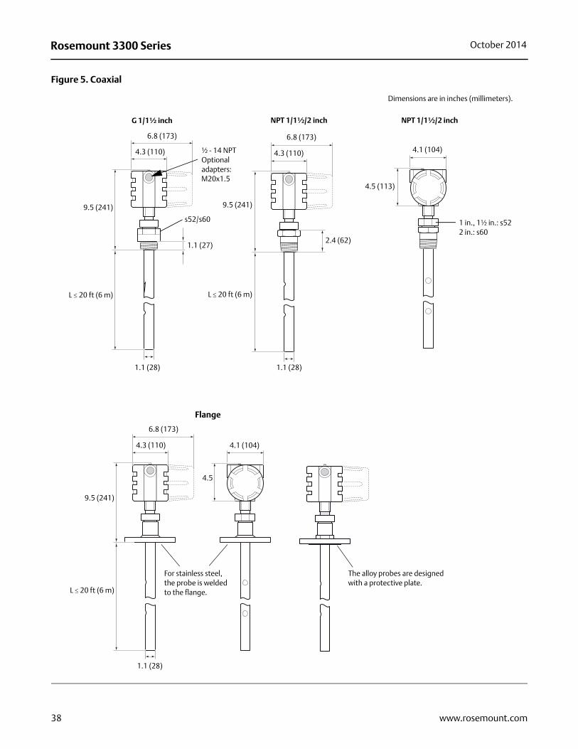
Figure 5. Coaxial
G 1/1½ inch NPT 1/1½/2 inch NPT 1/1½/2 inch
9.5 (241)
L 20 ft (6 m)
1.1 (28) 1.1 (28)
4.3 (110)
9.5 (241)
L 20 ft (6 m)
2.4 (62)
4.3 (110)
4.5 (113)
Dimensions are in inches (millimeters).
6.8 (173)
1.1 (27)
s52/s60
½ - 14 NPTOptional adapters:M20x1.5
6.8 (173)
1 in., 1½ in.: s522 in.: s60
4.1 (104)
4.3 (110)
9.5 (241)
L 20 ft (6 m)
1.1 (28)
4.5
Flange
The alloy probes are designed with a protective plate.
For stainless steel, the probe is welded to the flange.
6.8 (173)
4.1 (104)
38 www.rosemount.com

Rosemount 3300 SeriesOctober 2014
Figure 6. Rigid Twin Lead
4.1 (104)
s60
1.0 (25)
Ø 0.24 (6)
Ø 0.31 (8)
6.8 (173)
4.5 (113)
1½ in.: s522 in.: s60
L 10 ft. (3 m)
9.6 (244)
4.3 (110)
L 10 feet (3 m)
Ø 0.31 (8)
Ø 0.24 (6)
1.0 (25)
4.3 (110)
6.8 (173)½ - 14 NPTOptional adapters:M20x1.5
9.6 (244)
G 1½ inch NPT 1½ / 2 inch NPT 1½ / 2 inch
1.8 (45)1.1 (27)
Dimensions are in inches (millimeters).
1.0 (25)
4.3 (110)
6.8 (173)
9.6 (244)
Ø 0.31 (8)
Ø 0.24 (6)
4.1 (104)
4.5 (113)
L 10 ft. (3 m)
Flange
39www.rosemount.com

Rosemount 3300 Series October 2014
Figure 7. Flexible Twin Lead
Ø 1.4 (35)
s60
3.5 (90) 3.5 (90)
Ø 0.16 (4)
Ø 0.16 (4)
Ø 1.4 (35)
4.1 (104)
4.5 (113)
1.8 (45)
L 77 ft.(23.5 m)
4.3 (110)
6.8 (173)
9.6 (244)
L 77 ft.(23.5 m)
4.3 (110)
6.8 (173)
Ø 0.16 (4)
Ø 0.16 (4)
½ - 14 NPTOptional adapters:M20x1.5
9.6 (244)
G 1½ inch NPT 1½ / 2 inch NPT 1½ / 2 inch
1½ in.: s522 in.: s601.1 (27)
Dimensions are in inches (millimeters).
4.3 (110)
6.8 (173)
3.5 (90)
Ø 1.4 (35)
4.1 (104)
4.5 (113)
Ø 0.16 (4)
Ø 0.16 (4)
9.6 (244)
L 77 ft.(23.5 m)
Flange
40 www.rosemount.com

Rosemount 3300 SeriesOctober 2014
Figure 8. Bracket mounting
Dimensions are in inches (millimeters).
5.2 (133)
Pipe diameter max 2.5 in. (64 mm)
Pipe mounting(vertical pipe)
Pipe mounting(horizontal pipe)
Wall mounting Hole pattern wall mounting
0.8 (20)
2.8 (70)
2.2 (57)
0.3 (7)
41www.rosemount.com

Rosemount 3300 Series October 2014
Figure 9. Remote Housing
Figure 10. Proprietary Flanges
Dimensions are in inches (millimeters).
Hmin: 6.9 (175)Rmin 1.4 (35)
3, 6, 9 ft. (1, 2, or 3 m)5.2 (133)
Table 14. Dimensions of Proprietary Flanges
Special Flanges(1) D B1 B2 F G # Bolts K
Fisher 249B/259B(2) 9.00 (228.6) 1.50 (38.2) 1.25 (31.8) 0.25 (6.4) 5.23 (132.8) 8 7.25 (184.2)
Fisher 249C(3) 5.69 (144.5) 0.94 (23.8) 1.13 (28.6) -0.19 (-4.8) 3.37 (85.7) 8 4.75 (120.65)
Masoneilan(2) 7.51 (191.0) 1.54 (39.0) 1.30 (33.0) 0.24 (6.0) 4.02 (102.0) 8 5.87 (149.0)
(1) These flanges are also available in a vented version.
(2) Flange with raised face.
(3) Flange with recessed face.
D
B1
G
Raised Face Recessed Face
K
D: Outside diameter
B1: Flange thickness with gasket surface
B2: Flange thickness without gasket surface
F=B1-B2: Gasket surface thickness
G: Gasket surface diameter
# Bolts: Number of bolts
K: Bolt hole circle diameter
NoteDimensions may be used to aid in the identification of installed flanges. It is not intended for manufacturing use.
G
B1
DK
B2 B2
Dimensions are in inches (millimeters).
#
42 www.rosemount.com

Rosemount 3300 SeriesOctober 2014
43www.rosemount.com

Rosemount 3300 Series00813-0100-4811 Rev HA
Product Data SheetOctober 2014
Emerson Process ManagementBlegistrasse 23P.O. Box 1046CH 6341 BaarSwitzerlandTel +41 (0) 41 768 6111Fax + 41 (0) 41 768 6300www.rosemount.com
Emerson Process ManagementRosemount Inc.8200 Market BoulevardChanhassen, MN 55317 USAT (U.S.) 1-800-999-9307T (International) (952) 906-8888F (952) 906-8889www.rosemount.com
Emerson FZEP.O. Box 17033Jebel Ali Free ZoneDubai UAETel +971 4 811 8100Fax +971 4 886 5465www.rosemount.com
Emerson Process ManagementAsia Pacific Pte Ltd1 Pandan CrescentSingapore 128461Tel +65 6777 8211Fax +65 6777 [email protected]
Emerson Beijing Instrument CoNo. 6 North Street, HepingliDongcheng District, Beijing100013ChinaTel +8610 6428 2233Fax +8610 64287640www.rosemount.com
Emerson Process ManagementLatin America1300 Concord Terrace, Suite 400Sunrise Florida 33323 USATel +1 954 846 5030www.rosemount.com
Standard Terms and Conditions of Sale can be found at www.rosemount.com\terms_of_saleThe Emerson logo is a trade mark and service mark of Emerson Electric Co.Rosemount and the Rosemount logotype are registered trademarks of Rosemount Inc.PlantWeb is a registered trademark of one of the Emerson Process Management group of companies.HART and WirelessHART are registered trademarks of the HART Communication Foundation.Viton and Kalrez are registered trademarks of DuPont Performance Elastomers.Eurofast and Minifast are registered trademarks of Turck Inc.All other marks are the property of their respective owners.© 2014 Rosemount Inc. All rights reserved.
00813-0100-4811, Rev HA, 10/14