Embed Size (px)
Citation preview
1
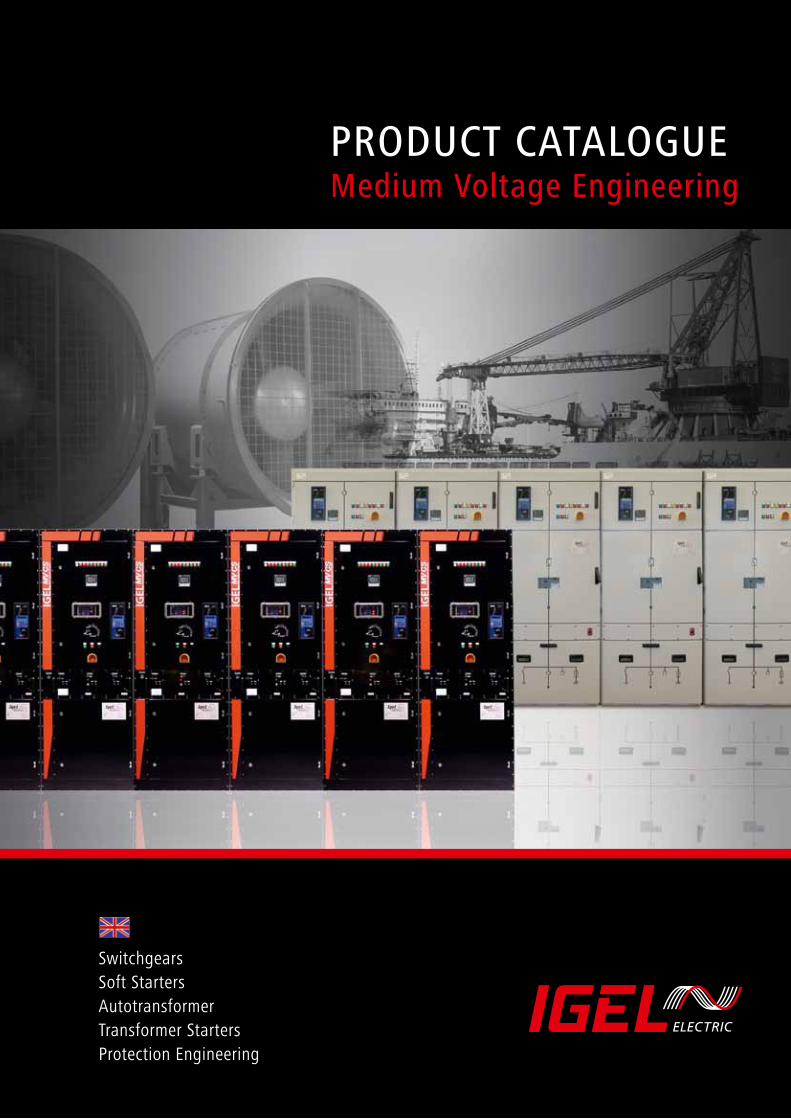
SwitchgearsSoft StartersAutotransformerTransformer StartersProtection Engineering
PRODUCT CATALOGUEMedium Voltage Engineering
2 3
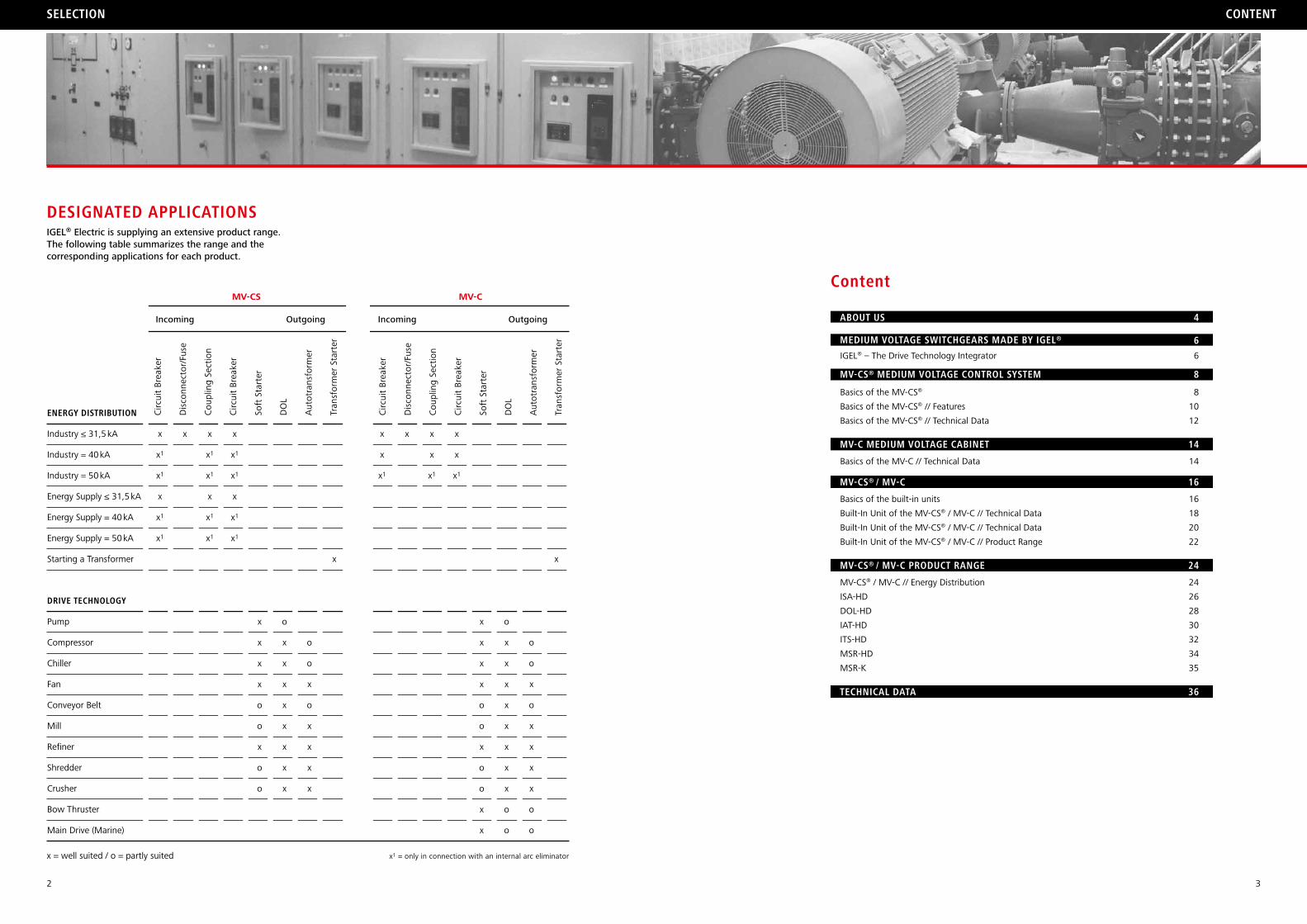
IGEL® Electric is supplying an extensive product range.The following table summarizes the range and the corresponding applications for each product.
selection content
x1 = only in connection with an internal arc eliminator
energy Distribution
Industry ≤ 31,5 kA
Industry = 40 kA
Industry = 50 kA
Energy Supply ≤ 31,5 kA
Energy Supply = 40 kA
Energy Supply = 50 kA
Starting a Transformer
Drive technology
Pump
Compressor
Chiller
Fan
Conveyor Belt
Mill
Refiner
Shredder
Crusher
Bow Thruster
Main Drive (Marine)
x
x1
x1
x
x1
x1
x x
x1
x1
x
x1
x1
x
x1
x1
x
x1
x1
x
x
x
x
o
o
x
o
o
o
x
x
x
x
x
x
x
x
o
o
x
o
x
x
x
x
x
x
x
x1
x x
x
x1
x
x
x1
x
x
x
x
o
o
x
o
o
x
x
o
x
x
x
x
x
x
x
x
o
o
o
o
x
o
x
x
x
x
o
o
x
MV-CS MV-C
Circ
uit
Brea
ker
Dis
conn
ecto
r/Fu
se
Cou
plin
g Se
ctio
n
Circ
uit
Brea
ker
Soft
Sta
rter
DO
L
Aut
otra
nsfo
rmer
Tran
sfor
mer
Sta
rter
Incoming Outgoing
DesignateD applications
content
about us
MeDiuM voltage sWitchgears MaDe by igel®
4
6
Mv-cs® MeDiuM voltage control systeM8
IGEL® – The Drive Technology Integrator
Basics of the MV-CS®
Basics of the MV-CS® // Features
Basics of the MV-CS® // Technical Data
8
10
12
16
18
20
22
24
26
28
30
32
34
35
14
6
Mv-c MeDiuM voltage cabinet 14
16
24
36
8
Basics of the MV-C // Technical Data
Mv-cs® / Mv-c
Basics of the built-in units
Built-In Unit of the MV-CS® / MV-C // Technical Data
Built-In Unit of the MV-CS® / MV-C // Technical Data
Built-In Unit of the MV-CS® / MV-C // Product Range
Mv-cs® / Mv-c proDuct range
technical Data
MV-CS® / MV-C // Energy Distribution
ISA-HD
DOL-HD
IAT-HD
ITS-HD
MSR-HD
MSR-K
x = well suited / o = partly suited
Incoming Outgoing
Circ
uit
Brea
ker
Dis
conn
ecto
r/Fu
se
Cou
plin
g Se
ctio
n
Circ
uit
Brea
ker
Soft
Sta
rter
DO
L
Aut
otra
nsfo
rmer
Tran
sfor
mer
Sta
rter
4 5
igel® electric gMbh
IGEL® – The Drive Technology Integrator
Founded in 2001 by former employees of the “Fanal” company in Wuppertal, IGEL® has design and market experience of more than 25 years in drive technology. Our long term cooperation with leading international component manufacturers since the beginning of the 80’s, gives us a leading edge in the soft starter market. IGEL® provides its customers with advanced technology and long term reliability.Today IGEL® Electric is technology leader offering the worldwide largest product range of soft starters. The first fully withdrawable medium voltage switchgear system MV-CS®, which was presented in 2009, emphasizes the development in order to become a leading Drive Technology Integrator.
Range of Services
Together with our customers we have accepted the global market challenges and our increasing sales have proven our concept to be well perceived. Last year the direct and indirect export has been more than 70 per cent. Our product range covers all voltage levels worldwide and guarantees our customers the drive solution from one source which reduces development- and adjustment costs. We provide unmatched local service and support in every geographical zone where we focus our activities.
To the international customer a “Made in Germany” product is perceived with utmost respect. It is the-refore that we must preserve this perception for our products as well, by continuously monitoring the quality, reliability and ruggedness of every step in the manufacturing process. Our design engineering criterions enhance our processes, and the exceptional choice of components that we are making, from the purchasing stage through manufacturing and delivery, is assuring maximum performance when the product reaches the customers’ site. From our marine products point of view, we have delivered Multi-Mega-Watt soft starters which have completely changed the way the marine market is propelled today. The certifications we have obtained are from some of the most stringent bodies in the indus-trial and marine market segments, and are genuine to our quality management, standards of product manufacturing.
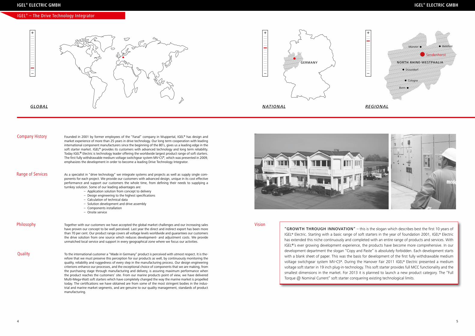
global national regional
Company History
igel® electric gMbh
GErmany nOrTh rhInE-WEsTphaLIa
Sendenhorst
Münster Bielefeld
Düsseldorf
Cologne
Bonn
+
–
+
–
+
–
Vision“GrOWTh ThrOuGh InnOvaTIOn” – this is the slogan which describes best the first 10 years of IGEL® Electric. Starting with a basic range of soft starters in the year of foundation 2001, IGEL® Electric has extended this niche continuously and completed with an entire range of products and services. With IGEL®’s ever growing development experience, the products have become more comprehensive. In our development department the slogan “Copy and Paste” is absolutely forbidden. Each development starts with a blank sheet of paper. This was the basis for development of the first fully withdrawable medium voltage switchgear system MV-CS®. During the Hanover Fair 2011 IGEL® Electric presented a medium voltage soft starter in 19 inch plug-in-technology. This soft starter provides full MCC functionality and the smallest dimensions in the market. For 2013 it is planned to launch a new product category. The “Full Torque @ Nominal Current” soft starter conquering existing technological limits.
As a specialist in “drive technology” we integrate systems and projects as well as supply single com-ponents for each project. We provide our customers with advanced design, unique in its cost effective performance and support our customers the whole time, from defining their needs to supplying a turnkey solution. Some of our leading advantages are: – Application solution from concept to delivery – Design engineering to the highest specifications – Calculation of technical data – Solution development and drive assembly – Components installation – Onsite service
Philosophy
Quality
6 7
MeDiuM voltage sWitchgear systeMs MaDe by igel® MeDiuM voltage sWitchgear systeMs MaDe by igel®
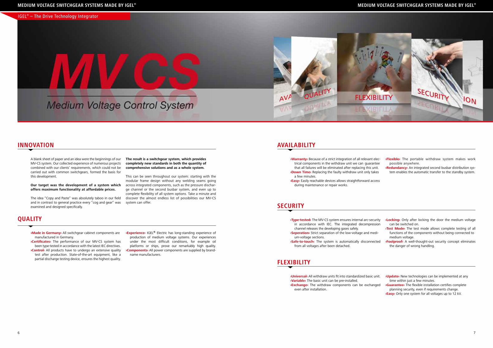
A blank sheet of paper and an idea were the beginnings of our MV-CS system. Our collected experience of numerous projects combined with our clients’ requirements, which could not be carried out with common switchgears, formed the basis for this development.
Our target was the development of a system which offers maximum functionality at affordable prices.
The idea “Copy and Paste” was absolutely taboo in our field and in contrast to general practice every “cog and gear” was examined and designed specifically.
The result is a switchgear system, which provides completely new standards in both the quantity of comprehensive solutions and as a whole system.
This can be seen throughout our system: starting with the modular frame design without any welding seams going across integrated components, such as the pressure dischar-ge channel or the second busbar system, and even up to complete flexibility of all system options. Take a minute and discover the almost endless list of possibilities our MV-CS system can offer.
innovation
›Warranty‹ Because of a strict integration of all relevant elec- trical components in the withdraw unit we can guarantee that all failures will be eliminated after replacing this unit.›Down Time‹ Replacing the faulty withdraw unit only takes a few minutes.›Easy‹ Easily reachable devices allows straightforward access during maintenance or repair works.
›Flexible‹ The portable withdraw system makes work possible anywhere.›Redundancy‹ An integrated second busbar distribution sys- tem enables the automatic transfer to the standby system.
availability
›Type-tested‹ The MV-CS system ensures internal arc-security in accordance with IEC. The integrated decompression channel releases the developing gases safely.›Seperation‹ Strict separation of the low-voltage and medi- um-voltage sections.›Safe-to-touch‹ The system is automatically disconnected from all voltages after been detached.
›Locking‹ Only after locking the door the medium voltage can be switched on.›Test Mode‹ The test mode allows complete testing of all functions of the components without being connected to medium voltage.›Foolproof‹ A well-thought-out security concept eliminates the danger of wrong handling.
security
›Universal‹ All withdraw units fit into standardized basic unit.›Variable‹ The basic unit can be pre-installed.›Exchange‹ The withdraw components can be exchanged even after installation.
›Update‹ New technologies can be implemented at any time within just a few minutes.›Guarantee‹ The flexible installation certifies complete planning security, even if requirements change.›Easy‹ Only one system for all voltages up to 12 kV.
FleXibility
›Made in Germany‹ All switchgear cabinet components are manufactured in Germany.›Certificates‹ The performance of our MV-CS system has been type-tested in accordance with the latest IEC directives.›Control‹ All products have to undergo an extensive quality test after production. State-of-the-art equipment, like a partial discharge testing device, ensures the highest quality.
›Experience‹ IGEL® Electric has long-standing experience of production of medium voltage systems. Our experiences under the most difficult conditions, for example oil platforms or ships, prove our remarkably high quality.›Components‹ All power components are supplied by brand- name manufacturers.
Quality
IGEL® – The Drive Technology Integrator
8 9
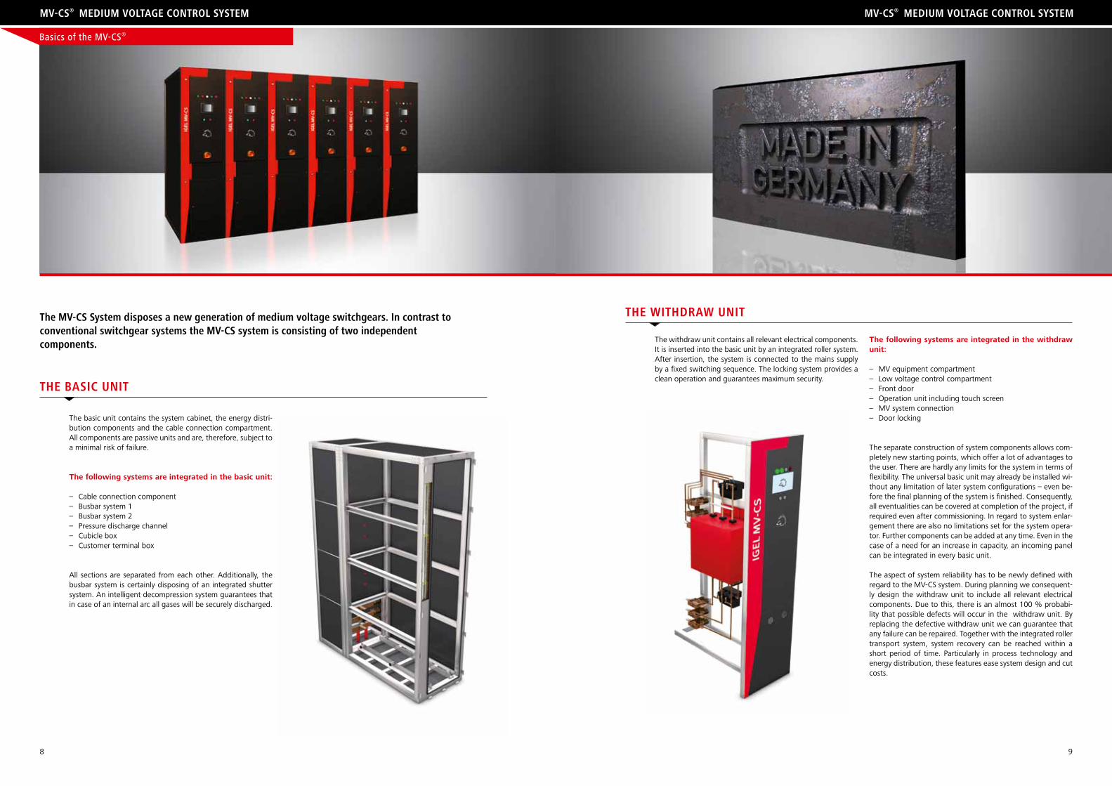
The basic unit contains the system cabinet, the energy distri-bution components and the cable connection compartment. All components are passive units and are, therefore, subject to a minimal risk of failure.
The following systems are integrated in the basic unit:
– Cable connection component– Busbar system 1– Busbar system 2– Pressure discharge channel– Cubicle box– Customer terminal box
All sections are separated from each other. Additionally, the busbar system is certainly disposing of an integrated shutter system. An intelligent decompression system guarantees that in case of an internal arc all gases will be securely discharged.
the Mv-cs system disposes a new generation of medium voltage switchgears. in contrast to conventional switchgear systems the Mv-cs system is consisting of two independentcomponents.
Mv-cs® MeDiuM voltage control systeM Mv-cs® MeDiuM voltage control systeM
the basic unit
The withdraw unit contains all relevant electrical components. It is inserted into the basic unit by an integrated roller system. After insertion, the system is connected to the mains supply by a fixed switching sequence. The locking system provides a clean operation and guarantees maximum security.
The following systems are integrated in the withdraw unit:
– MV equipment compartment– Low voltage control compartment– Front door– Operation unit including touch screen– MV system connection – Door locking
The separate construction of system components allows com-pletely new starting points, which offer a lot of advantages to the user. There are hardly any limits for the system in terms of flexibility. The universal basic unit may already be installed wi-thout any limitation of later system configurations – even be-fore the final planning of the system is finished. Consequently, all eventualities can be covered at completion of the project, if required even after commissioning. In regard to system enlar-gement there are also no limitations set for the system opera-tor. Further components can be added at any time. Even in the case of a need for an increase in capacity, an incoming panel can be integrated in every basic unit.
The aspect of system reliability has to be newly defined with regard to the MV-CS system. During planning we consequent-ly design the withdraw unit to include all relevant electrical components. Due to this, there is an almost 100 % probabi-lity that possible defects will occur in the withdraw unit. By replacing the defective withdraw unit we can guarantee that any failure can be repaired. Together with the integrated roller transport system, system recovery can be reached within a short period of time. Particularly in process technology and energy distribution, these features ease system design and cut costs.
the WithDraW unit
Basics of the MV-CS®
10 11
Mv-cs® MeDiuM voltage control systeM Mv-cs® MeDiuM voltage control systeM
Our MV-CS system offers several innovative concepts for fai-lure elimination. When highest system availability is required, the complete withdraw unit can be replaced within some mi-nutes. Based on the 100:0 failure distribution between with-draw and basic units, there is a failure elimination guarantee with the exchange of units. This means, your system is servi-ceable within a couple minutes. Guaranteed!
In the case of less critical applications, the full maintenance performance also applies to a repair. Barrier-free access, wor-king independently from the systems’ position and our Test Kit assure an almost effortless and time-optimised repair. Fi-nally, the consequent safety concept assures an accident-free work process, even for the inexperienced.
Failure eliMination
Flexibility and cost reduction are one of the leading targets at nearly every product development. The framework de-sign is an essential part of our MV-CS and has been optimi-sed according to these requirements. The result is a system, which combines both goals (cost reduction and flexibility) ideally. The switchgear framework design consists of a lot of production and transport optimised components. Almost eve-ry steel works can produce these components and transport
them in standardized boxes. The components will then be connected with a special riveting procedure in the plant. This assures, on the one hand, minimised production time and on the other hand consistent quality. Particularly in connection with ship applications, the flexible construction assures good shock- and vibrations stability and therefore offers a basis for the installation in this ambitious market segment.
sWitchgear FraMeWorK Design
This concept is only known in the IT world. The MV-CS system is able to transfer this philosophy into the medium voltage area. Moreover the system is capable to “Hot Swap”. Single withdraw systems can be interchanged, while the other sys-tem components continue to work at their usual level. Due to the standardised terminal block, every withdraw unit can then be inserted and the operation of this unit can be guaranteed.
Staying with this idea in the IT field, it is possible to say the system is fully updatable. Old technologies can be exchanged for new ones within a few minutes, without switching the entire system off.
plug anD play
The MV-CS system’s locking concept opens new doors. The door design is the most noticeable feature. The door does not hang on hinges but is a fixed part of the withdraw unit. When the system is inserted, the locking bolts of the basic unit interlock with the door’s framework. With just one single motion the whole system will be locked on all sides. After complete locking of the front door, the system complies with
the IEC internal arc test requirements. Due to this medium vol-tage contact is impossible until the door has been locked. The contact and locking concept guarantees even inexperienced users safe work environment conditions.
locKing concept
maintenance can take place nearly everywhere. Consequently the works can be done at a comfortable place, like the work-shop. As a highlight, a test kit is at your disposal, which ena-bles a complete check of the system while the unit has been removed. Due to this, the functionality of the maintained sys-tem is guaranteed.
You can already start thinking of additional tasks for the main-tenance team. Our MV-CS system offers a unique “mainte-nance-friendliness”. For all incurring works the withdraw unit can be completely removed and is, therefore, accessible from all sides. All components are reachable without any barriers, which minimises time requirements. Moreover it should be said, that the withdraw system is portable, which means
Maintenance
In the MV-CS system’s basic unit a decompression channel is integrated. The channel is fully incorporated into the innova-tive security concept of the switchgear system and also makes new design approaches possible. Through our decompres-
sion concept room planning and difficulties in engineering are clearly minimised. Because no additional components are needed installation costs are reduced.
integrateD DecoMpression concept
systeM integration Drive technology
Standard Switchgear
ISA-HD
(integrated Soft Starter)
M13~
Power Input Transformer-Outgoing Motor-Outgoing
ISA-HDSOFT STARTER
Soft Starter
M13~
Power Input Transformer-Outgoing Motor-Outgoing
SOFT STARTERISA-HD
(integrated Soft Starter)
M13~
Power Input Transformer-Outgoing Motor-Outgoing
ISA-HDSOFT STARTER
Soft Starter
M13~
Power Input Transformer-Outgoing Motor-Outgoing
SOFT STARTER
Basics of the MV-CS®
12 13
Mv-cs® MeDiuM voltage control systeM Mv-cs® MeDiuM voltage control systeM
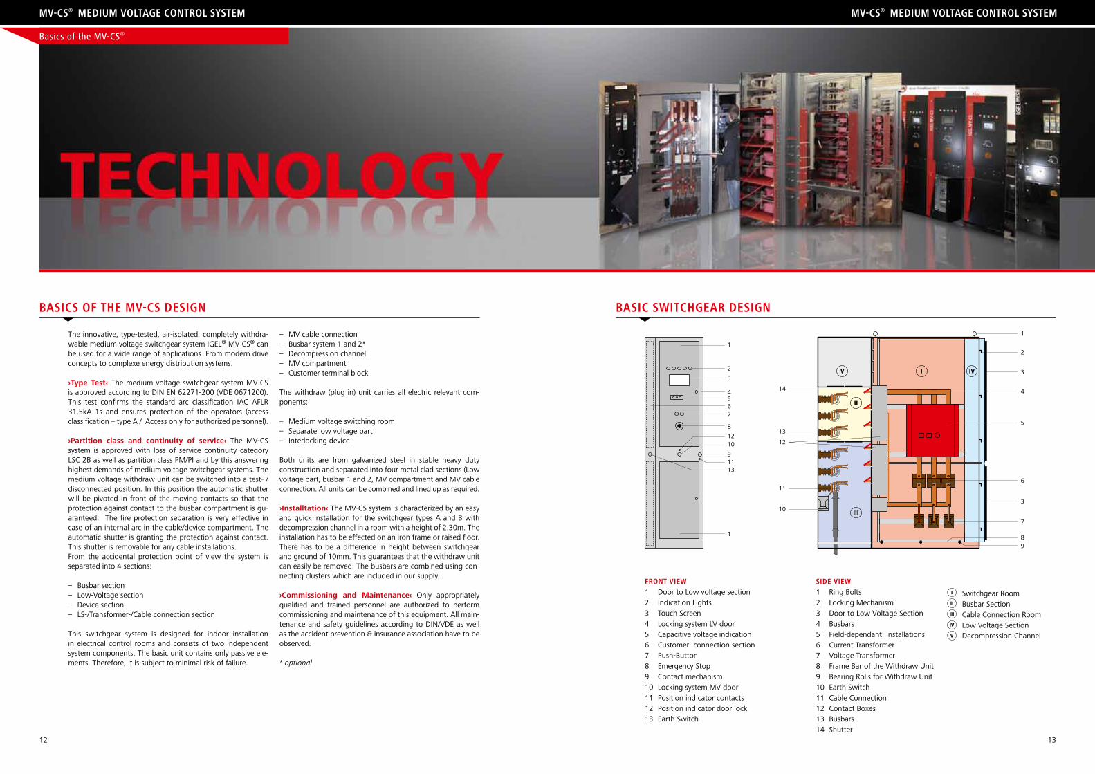
basics oF the Mv-cs Design basic sWitchgear Design
siDe vieW1 Ring Bolts2 Locking Mechanism3 Door to Low Voltage Section4 Busbars5 Field-dependant Installations6 Current Transformer7 Voltage Transformer8 Frame Bar of the Withdraw Unit 9 Bearing Rolls for Withdraw Unit10 Earth Switch11 Cable Connection12 Contact Boxes13 Busbars14 Shutter
The innovative, type-tested, air-isolated, completely withdra-wable medium voltage switchgear system IGEL® MV-CS® can be used for a wide range of applications. From modern drive concepts to complexe energy distribution systems.
›Type Test‹ The medium voltage switchgear system MV-CS is approved according to DIN EN 62271-200 (VDE 0671200). This test confirms the standard arc classification IAC AFLR 31,5kA 1s and ensures protection of the operators (access classification – type A / Access only for authorized personnel).
›Partition class and continuity of service‹ The MV-CS system is approved with loss of service continuity category LSC 2B as well as partition class PM/PI and by this answering highest demands of medium voltage switchgear systems. The medium voltage withdraw unit can be switched into a test- / disconnected position. In this position the automatic shutter will be pivoted in front of the moving contacts so that the protection against contact to the busbar compartment is gu-aranteed. The fire protection separation is very effective in case of an internal arc in the cable/device compartment. The automatic shutter is granting the protection against contact. This shutter is removable for any cable installations. From the accidental protection point of view the system is separated into 4 sections:
– Busbar section– Low-Voltage section– Device section– LS-/Transformer-/Cable connection section
This switchgear system is designed for indoor installation in electrical control rooms and consists of two independent system components. The basic unit contains only passive ele-ments. Therefore, it is subject to minimal risk of failure.
Basics of the MV-CS®
1
2
3
4567
8
1210
91113
1
IV IV
III
II
1
2
3
3
4
5
6
7
89
10
11
12
13
14
Switchgear RoomBusbar SectionCable Connection RoomLow Voltage SectionDecompression Channel
I
V
IV
III
II
– MV cable connection– Busbar system 1 and 2*– Decompression channel– MV compartment– Customer terminal block
The withdraw (plug in) unit carries all electric relevant com-ponents:
– Medium voltage switching room– Separate low voltage part– Interlocking device
Both units are from galvanized steel in stable heavy duty construction and separated into four metal clad sections (Low voltage part, busbar 1 and 2, MV compartment and MV cable connection. All units can be combined and lined up as required.
›Installtation‹ The MV-CS system is characterized by an easy and quick installation for the switchgear types A and B with decompression channel in a room with a height of 2.30m. The installation has to be effected on an iron frame or raised floor. There has to be a difference in height between switchgear and ground of 10mm. This guarantees that the withdraw unit can easily be removed. The busbars are combined using con-necting clusters which are included in our supply.
›Commissioning and Maintenance‹ Only appropriately qualified and trained personnel are authorized to perform commissioning and maintenance of this equipment. All main-tenance and safety guidelines according to DIN/VDE as well as the accident prevention & insurance association have to be observed.
* optional
Front vieW1 Door to Low voltage section2 Indication Lights3 Touch Screen4 Locking system LV door 5 Capacitive voltage indication6 Customer connection section7 Push-Button8 Emergency Stop9 Contact mechanism10 Locking system MV door11 Position indicator contacts 12 Position indicator door lock13 Earth Switch
14 15
Mv-c MeDiuM voltage cabinet Mv-c MeDiuM voltage cabinet
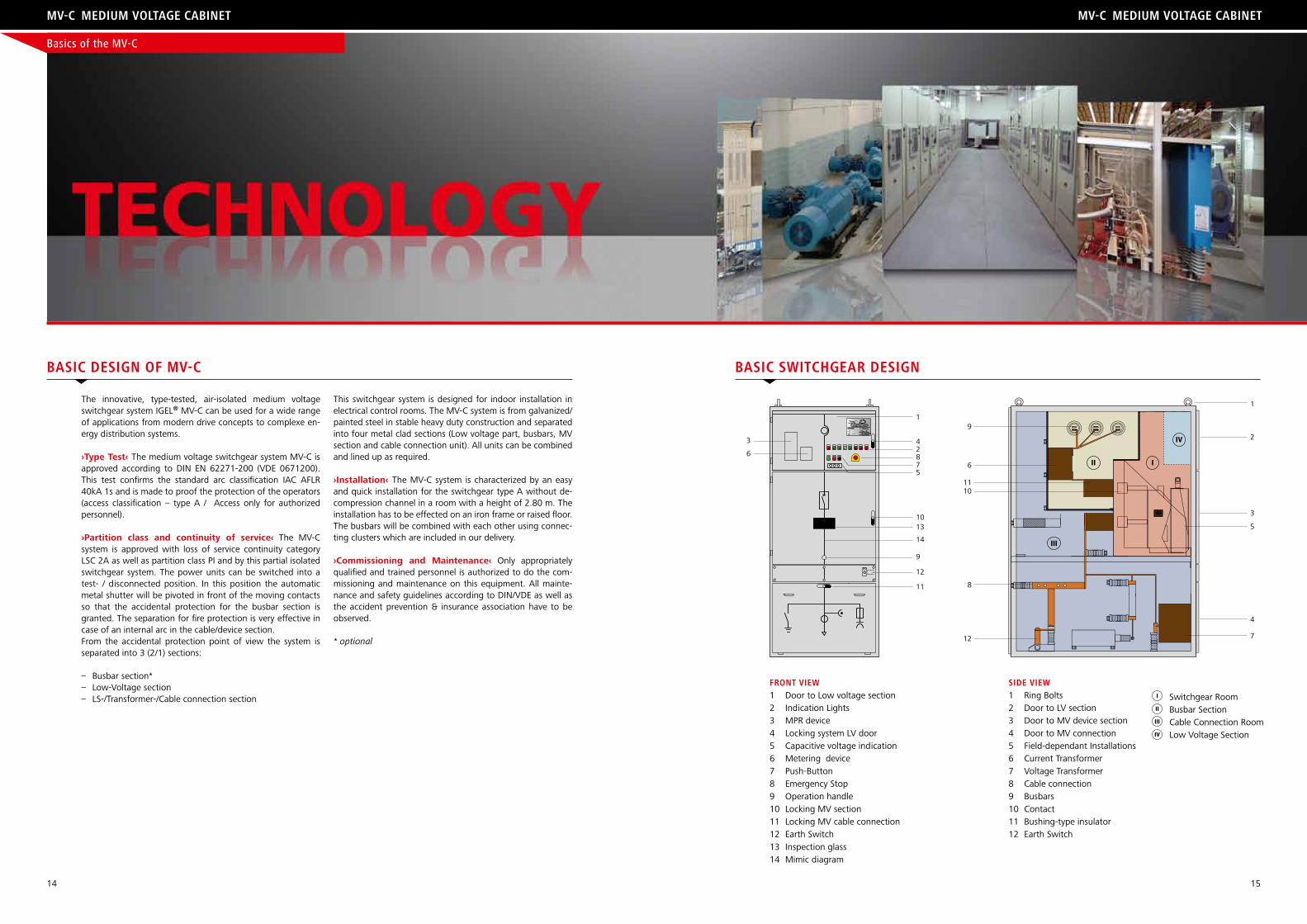
basic Design oF Mv-c
The innovative, type-tested, air-isolated medium voltage switchgear system IGEL® MV-C can be used for a wide range of applications from modern drive concepts to complexe en-ergy distribution systems.
›Type Test‹ The medium voltage switchgear system MV-C is approved according to DIN EN 62271-200 (VDE 0671200). This test confirms the standard arc classification IAC AFLR 40kA 1s and is made to proof the protection of the operators (access classification – type A / Access only for authorized personnel).
›Partition class and continuity of service‹ The MV-C system is approved with loss of service continuity category LSC 2A as well as partition class PI and by this partial isolated switchgear system. The power units can be switched into a test- / disconnected position. In this position the automatic metal shutter will be pivoted in front of the moving contacts so that the accidental protection for the busbar section is granted. The separation for fire protection is very effective in case of an internal arc in the cable/device section. From the accidental protection point of view the system is separated into 3 (2/1) sections:
– Busbar section*– Low-Voltage section– LS-/Transformer-/Cable connection section
This switchgear system is designed for indoor installation in electrical control rooms. The MV-C system is from galvanized/painted steel in stable heavy duty construction and separated into four metal clad sections (Low voltage part, busbars, MV section and cable connection unit). All units can be combined and lined up as required.
›Installation‹ The MV-C system is characterized by an easy and quick installation for the switchgear type A without de-compression channel in a room with a height of 2.80 m. The installation has to be effected on an iron frame or raised floor. The busbars will be combined with each other using connec-ting clusters which are included in our delivery.
›Commissioning and Maintenance‹ Only appropriately qualified and trained personnel is authorized to do the com-missioning and maintenance on this equipment. All mainte-nance and safety guidelines according to DIN/VDE as well as the accident prevention & insurance association have to be observed.
* optional
basic sWitchgear Design
Basics of the MV-C
1
42875
1013
14
9
12
11
3
6
Front vieW1 Door to Low voltage section2 Indication Lights3 MPR device4 Locking system LV door 5 Capacitive voltage indication6 Metering device7 Push-Button8 Emergency Stop9 Operation handle10 Locking MV section 11 Locking MV cable connection 12 Earth Switch13 Inspection glass14 Mimic diagram
siDe vieW1 Ring Bolts2 Door to LV section3 Door to MV device section 4 Door to MV connection 5 Field-dependant Installations6 Current Transformer7 Voltage Transformer8 Cable connection 9 Busbars10 Contact11 Bushing-type insulator12 Earth Switch
1
2
3
5
4
712
8
1011
6
9
I
IV
III
II
Switchgear RoomBusbar SectionCable Connection RoomLow Voltage Section
I
IV
III
II
16 17
Mv-cs® / Mv-c Mv-cs® / Mv-c
Basics of the Built-In Units
The IGEL® Electric Company develops, produces and sells me-dium voltage switchgear systems of a new generation. In this context the two switchgear systems MV-C and MV-CS present the “external frame” for the installed switchgear technique. The electrical relevant components are subject to a strict qua-lity control and will be selected according to the requested demands of each order. Not only the IGEL® parts are subject to this quality control but also all standard components of the switchgear technique.
A basic advantage is the independence of the design in re-spect of the manufacturers. All switchgear systems have been developed for all common switchgear devices. Due to this product-neutral platform IGEL® Electric will be in the position to always select the most convenient switchgear device. On the one hand the selection criteria may be based on technical
aspects like e.g. switching frequency, short circuit withstand or class. On the other hand our experiences with special pro-duct lines as well as the price play a decisive role. Additionally, we are able to meet the requirements of our customers by installing the requested switchgear devices, without being dependent on the switchgear of a single manufacturer. This also considerably reduces the spare part storage costs of our customers.
In the following the key requirements of the most important switchgear devices and components are listed.
sWitchgear
›Circuit Breaker‹according to standard: IED 62 271-100, vDE 0671-100Main switches are principally used in the field of energy dis-tribution. The main selection criteria are the switching per-formance as well as the short circuit power. For larger drive systems the main switches will be installed in the line- and bypass. In this special case the switching frequency is an ad-ditional selection criterion. ›Earth Switch‹according to standard: IEC 62 271-102; vDE 0671-102Earth switches have the function to first of all protect the personnel which is working on the switchgear or the con-nected switchgear parts. Depending on their configuration they should guarantee that there is no voltage in the panels.
›Fuses‹according to standard: IEC 60 282; vDE 0670-4Fuses are installed for switchgear and user protection. In the opposite to the circuit breaker the fuses limit the short-circuit current to a considerably lower maximum current value. This enables that some parts of the switchgear may be according to a lower short circuit as well as internal arc classification since they will be protected by the fuses. From the techni-cal point of view fuses are only applicable to a certain size. The performance limits may be extended in case of parallel switchgears.
›Load break switch‹according to standard: IEC 60 265-1; vDE 0670-301 In a medium voltage switchgear system the load break swit-ches will principally be used as control elements. By the load break switches certain sections of the switchgear system may be connected or disconnected.
›Isolation‹according to standard: IEC 60 071; vDE 0111
›Voltage transformers‹according to standard: IEC 60 044-2; vDE 0414-2 Voltage transformer will nearly be installed in every switch-gear system. Depending on the protection concept the vol-tage level is observed directly, will be switched off in certain situations or will only be indicated and passed on to the next higher-ranking protection installation.
›Current transformers‹according to standard: IEC 60 044-1, vDE 0414-1Current transformers form the basics of each protection sys-tem. Depending on the requested performances we use de-vices with the corresponding precision and saturation class. Especially in drive technology we often use double core trans-former since besides the protection function the transformer also is providing the control value for the drive technology.
›Contactors‹according to standard: IEC 60 470; vDE 60 871-1All contactors used in the medium voltage area are realized using the vacuum technique. These contactors provide a ma-ximum of switching possibilities and additionally may with-stand but not switch a certain short circuit current. Therefore, we have to install short circuit limiting elements upstream of the contactors. In case the net has high short circuit power the fuses have to be positioned upstream or circuit breakers have to be installed.
›Capacitors‹according to standard: IEC 60 871-1Capacitors are used to improve the power factor. Because of the extensive distribution of power electronics the harmonics should always be considered when deciding for a product. In case of doubt the capacitors have to be protected against high frequency disturbance by installing upstream connected chokes. For soft starter applications in general the careful se-lection of capacitors is granting the availability of the switch-gear.
18 19
Mv-cs® / Mv-c Mv-cs® / Mv-c
›Definition‹ The incoming field is referred to all fields which are used for the energy feeding of the switchgear system. In this case the source of supply voltage (transformer, out- going field, generator) is not decisive.›Applications‹ The incoming fields may be used for energy distribution as well as for drive technology systems. They have to connect the supply voltage with the busbar sys- tem of the switchgear system by installing the correspon- ding components.›Design‹ In general incoming fields will be equipped with withdrawable cuircut breakers. In combination with the corresponding protection device they guarantee the
›Definition‹ The outgoing field is referred to all fields which form the outgoing of a system and are connected to ano- ther system or the end user.›Applications‹ The outgoing fields are switching and controlling the connected systems. They also dispose of protection functions like e.g. the motor or overcurrent protection relay. ›Design‹ Depending on the demands of the connected system the corresponding components will be installed. In case of a low switching frequency (e.g. transformer)
protection of the switchgear system. Furthermore, the disconnector/fuse combination is installed very often. ›Features‹ Since the incoming fields are directly connected to the external supply voltage which in most cases will be supplied from components outside the control room special features are requested. A special locking mechanism has to guarantee that neither a switching operation in the incoming field nor in the upstream connected supply field cause an undesirable status (e.g. short circuit).
the outgoing field will be equipped with a circuit breaker or a main switch with fuses. For high switching frequencies (e.g. motor) vacuum contactors or a motor starting system has to be built in.›Features‹ For outgoing fields the personal protection is an important criterion. In order to guarantee safe works on connected components all outgoing cables are grounded. Additionally, a locking system is securing the outgoing field against unintentional reconnection.
outgoing FielD
›Definition‹ Coupling fields are referred to all fields which are connecting two busbar systems (coupling).›Applications‹ Complexe switchgear systems e.g. redundant systems or switchgear systems with two incoming fields have to offer the possibility of different con- figurations. In this case the coupling fields serve as connecting or final controlling element. ›Design‹ As switching component either disconnectors or circuit breakers are used.
›Features‹ Like the incoming fields also the coupling fields may produce unwanted and critical switching statuses. Therefore, all switching components which are installed into the coupling fields have to be completely integrated into the locking system.
coupling FielD
Often additional fuses, earth disconector as well as motor protection relays are installed into a soft starter.›Features‹ During the motor start-up the power electronic is producing heat. This has to be considered for the switch- gear design. The signal transmission by using fibre optics is granting a strict separation between low voltage and medium voltage section.
›Definition‹ Soft starters are designed to provide a smooth and stepless acceleration of electrical asynchronous mo- tors by using power electronic components (Thyristors). ›Applications‹ Applications which need a motor start to be grid protecting (reduced starting current) and/or mechanic protecting (reduced starting torque). ›Design‹ A soft starter always is with built in power electronic the so called power stacks. In the medium voltage section a bypass contactor as well as main switch are prescribed.
soFt starter
protection relay. Vacuum contactors are often used in combination with the corresponding fuses.›Features‹ See outgoing-field.
›Definition‹ Start-up units which start the motor by using common switching components (vacuum contactor or power switch).›Applications‹ Applications without any critical phase dur- ing start up in respect of loading the grid and torque peaks. ›Design‹ Switching component in form of a vacuum contac- tor or circuit breaker. Current transformer and motor
Dol / star-Delta
transformers and motor protection relays are installed.›Features‹ The high weight as well as the dimensions of this special transformer make it necessary to supply the starting transformer field in extended design.
›Definition‹ Autotransformers are motor start-up units using transformers tapping on the secondary part and supplying the motor with the corresponding ramped voltage.›Applications‹ Applications which need a reduced current during starting phase.›Design‹ Special transformer in the Korndorfer transition principle using specific switching components and supp- lying the motor with the corresponding ramped voltage. Very often protection components like fuses, current
autotransForMer
incoMing FielD
Built-In Units of the MV-CS® / MV-C
20 21
Mv-cs® / Mv-c Mv-cs® / Mv-c
Autotransformers in the Korndorfer transition principle reduce the motor voltage during the starting phase using a transfor-mer and the corresponding contactor control. The transfor-mer is tapping on the secondary part according to the cal-culated starting parameters and is supplying the motor with the corresponding reduced voltage. When motor reaches full speed the transformer star contactor will be switched off. During this phase the windings in the transformer serve as in-line inductance and bridge over the time until the by-pass contactors will be connected. This avoids voltage as well as current peaks when switching from starting voltage to nomi-nal voltage.
›Advantages‹ The transformer effect is reducing the main supply according to the transmission ratio motor voltage/line voltage. This starting method offers advantages for the heavy-duty starting.
›Disadvantages‹ During the starting phase the voltage is fix and cannot respond to application or mains fluctuations. The step increase of the starting current and the starting torque is producing mechanical and electric stress.
autotransForMers
›Advantage‹ : More economical than other starting methods. Small and not technically demanding.
›Disadvantage‹ High starting current and high starting tor-que. Current and torque peaks load the grid as well as the mechanic of the driven machine.
The direct online start is an electric mechanical procedure and starts the motor using mechanical switching components e.g. vacuum contactors or circuit breakers. The direct online start is still the most common starting procedure for asynchronous motors. Should there occur no mechanical or electrical stress during the starting phase this solution is an absolutely suffici-ent and an especially cost efficient method.
Dol
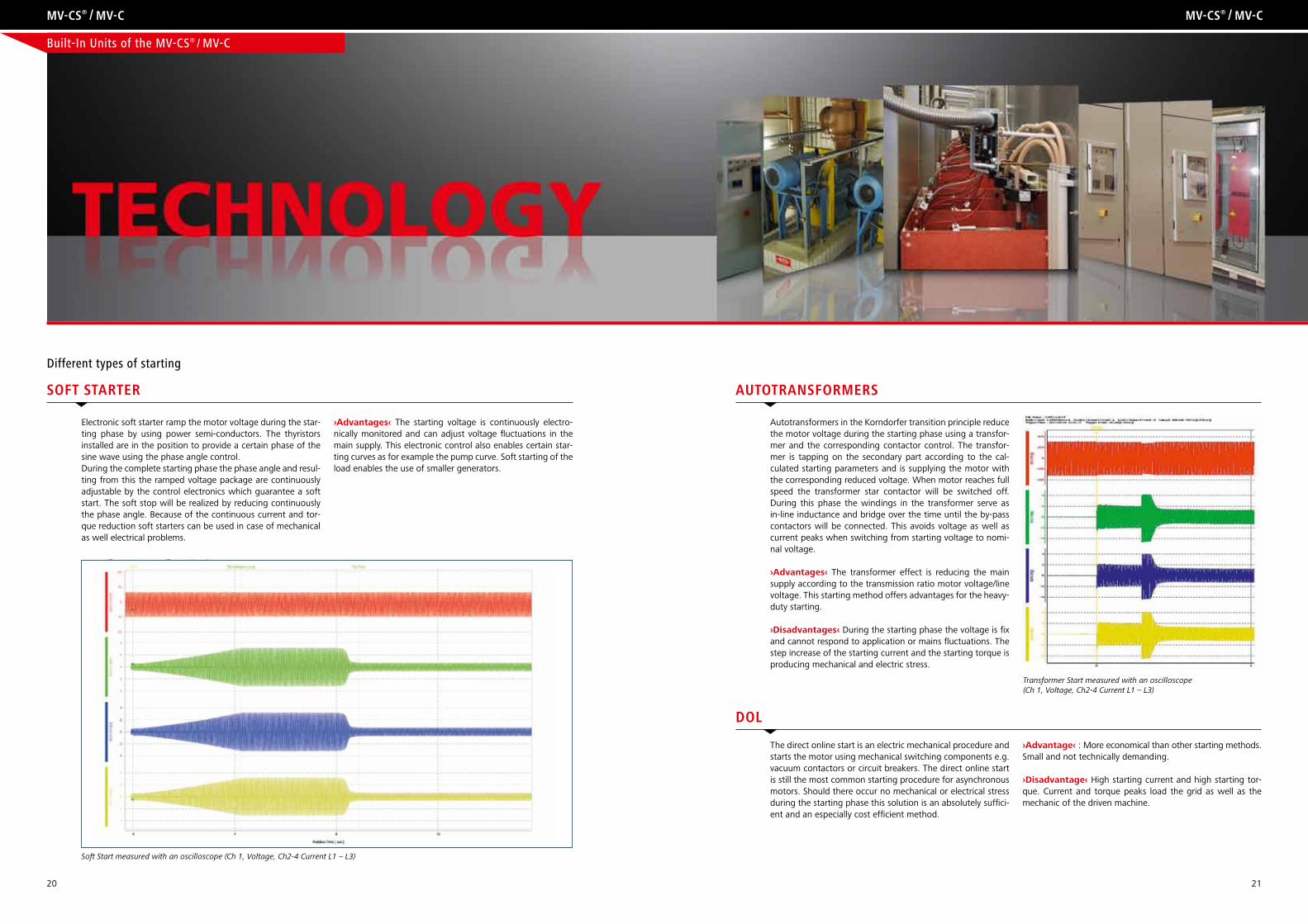
Electronic soft starter ramp the motor voltage during the star-ting phase by using power semi-conductors. The thyristors installed are in the position to provide a certain phase of the sine wave using the phase angle control. During the complete starting phase the phase angle and resul-ting from this the ramped voltage package are continuously adjustable by the control electronics which guarantee a soft start. The soft stop will be realized by reducing continuously the phase angle. Because of the continuous current and tor-que reduction soft starters can be used in case of mechanical as well electrical problems.
›Advantages‹ The starting voltage is continuously electro-nically monitored and can adjust voltage fluctuations in the main supply. This electronic control also enables certain star-ting curves as for example the pump curve. Soft starting of the load enables the use of smaller generators.
soFt starter
Different types of starting
Soft Start measured with an oscilloscope (Ch 1, Voltage, Ch2-4 Current L1 – L3)
Transformer Start measured with an oscilloscope(Ch 1, Voltage, Ch2-4 Current L1 – L3)
Built-In Units of the MV-CS® / MV-C
22 23
COMPONENT SELECTION TABLE MV-CS / MV-C COMPONENTS (LEGEND)
Mv-cs® / Mv-c Mv-cs® / Mv-c
Mv-cs Mv-c
soFt starter panel star-Delta-panelauto transForMer panel
circuit breaKer panel
contactor panel
coupling panel contactor panel coupling panel
circuit breaKer panel
MulitMotor panel
soFt starter panel
universal FielD
HH-Fuse
Capacitive Voltage Indicator
Motor Protection Relay
CurrentTransformer
Surge Protection
VacuumContactor
Earthing
Load Breaker
Multifunction Display
VoltageTransformer
Vacuum Circuit Breaker
Protcetion RelayUMZ
Circuit Breaker Panel
Contactor Panel
Coupling Panel
Universal Field
Soft Starter Panel
Multimotor Panel
Auto Transformer Panel
Star-Delta Panel
Components
x x x x x x x x
x x x x x x x x x x
x x x x x x
x x x x x x x x x x x x
x x x x x x x
x x x x x x x x
x x x x x x x x
x x x x x x x x x
MSR UMZ
x = possible option
Built-In Units of the MV-CS® / MV-C
24 25
– „Factory assembled, type tested medium voltage switchgears according to DIN EN 62271-200 (VDE 0671-200)– Metal-enclosed and metal-clad indoor-switchgear systems – Locking system according to IEC 62271-200/VDE 0671-200– All MV switching activities are only allowed with locked medium voltage door– Decompression channel integrated or on top– Flexible, brand-neutral switchgear technique– Up to 50°C ambient temperature– Comprehensive motor protection and control package– IP 41 as standard, up to IP 54 optional– Electronic potential transformer for voltage measurement and protection– Frequency range between 50 – 60Hz – Engineering included – Innovative low voltage test– Nominal voltage test – option
– IEC 62 271-200 tested– MV-CS or MV-C– LSC1, LSC2A, LSC2B– Up to 50kA upon request– Incoming field– Outgoing field– Transformer outgoing field– Coupling field– Measuring field – Current and voltage transformer– Power factor control – Tin plated busbars– Isolated busbars– Specially insulated cable glands– Special thick paint – Fan system – increased cooling– Control voltage: 110V – 220V AC, 24V – 220V DC– Halogen free and fire retardant materials – Marine Version– DIN GOST Version – Special dimensions
– Manufacturer-neutral– Feeder protection– AMZ– Motor protection– Transformer protection– Differential protection
– Multi-function programmable I/O’s– Opto-isolated control in- and outputs– Transformer 8A/250V– Analogue outputs– Analogue inputs– Profibus / Modbus– Touchscreen– SPS
Mv-cs® / Mv-c proDucts
control
protection options sWitchgear optionsaDvantages at a glance
Mv-cs / Mv-cEnergy Distribution
system voltage Current short Circuit Testing voltage Dimensions (mm) Weightkv a ka kv W h D kg
FusE-COnTaCTOr-COmbInaTIOn
3,6 320 16 – 31,5 20 / 40 600 – 1.000 2.300 900 – 1.200 450 – 1.100
7,2 400 16 – 31,5 20 / 60 600 – 1.000 2.300 900 – 1.200 500 – 1.200
12,0 400 16 – 31,5 28 / 75 900 – 1.000 2.300 900 – 1.700 500 – 1.200
17,5 320 16 – 31,5 38 / 95 1.000 – 1.200 2.300 900 – 1.700 800 – 1.300
CIrCuIT brEakEr
3,6 630 – 2.500 16 – 50* 20 / 40 600 – 1.000 2.300 900 – 1.200 450 – 1.100
7,2 630 – 2.500 16 – 50* 20 / 60 600 – 1.000 2.300 900 – 1.200 500 – 1.200
12,0 630 – 2.500 16 – 50* 28 / 75 900 – 1.000 2.300 900 – 1.700 500 – 1.200
17,5 630 – 2.500 16 – 50* 38 / 95 1.000 – 1.200 2.300 900 – 1.700 800 – 1.300
* 40 / 50 kA on request
Range 630 – 2. 500 A and 3,6 – 17 ,5 kV
1)1) 1)1)1)1)1)
approvals
1) case by case
Mv-cs® / Mv-c proDucts
26 27
– Up to 50°C ambient temperature– Comprehensive motor protection and control package– IP 41 as standard, up to IP65 optional– Advanced electronic potential transformer utilizing patent pending “wireless” voltage measurement system– Wide 45 – 65Hz range auto-frequency tracking – Engineering included– Automatic triggering of the firing angle (designed for marine, offshore and generator operating under continuous frequency variation)– Innovative low voltage test – testing of complete function– Nominal voltage test – option– Unique, patent pending fiber-optic firing system providing complete isolation between MV and LV compartments– Each soft starter is tested for partial discharge improving safety and ensuring long term reliability– Synchronous motor starting, utilizing unique module– Real-Time-Clock
– IEC 62 271-200 tested– MV-CS or MV-C– LSC1, LSC2A, LSC2B– Up to 50 kA upon request– Incoming field– Multi motor– Circuit breaker– Earth switch / Earth bolt– MV-fuses with striker-pin indication– Load disconnector – Current and voltage transformer– Power factor control– In-line-mouting – Tin plated busbars– Isolated busbars– Specially insulated cable glands– Motor Protection Relay– Differential Relay– Multifunction Display– Special thick paint– Fan system – increased cooling– Control voltage: 110V – 220V AC, 24V – 220V DC– Halogen free and fire retardant materials– Marine Version– DIN GOST Version – Special dimensions
Industrial– Compressors– Fans and blowers– Centrifuges– Hydraulic systems– Conveyors– Mills, crushers, shredders
marine and Offshore– Water and ballast pumps – Refrigeration chillers and compressors (hydraulic aggregates) – Thrusters– Main propulsion motors– Cargo Pumps– Generator ready – auto frequency tracking
– MSR-HD– MSR-K– Display– Too many starts– Too long starts– Electronic shear-pin– Short circuit protection– Under current– Asymmetric load– Ground fault current– Phase loss and phase sequence– Over/under frequency– Under/over voltage– External fault– PT 100 protection– Shorted SCR– Wrong motor connection– Starter over temperature– Power on without start signal– Open bypass contactor
– Closed control circuit through current measuring– Multi-function programmable I/O’s– Opto-isolated control in- and outputs– Transformer 8A/250V– Analogue outputs– Analogue inputs– Modbus / Profibus– Touchscreen – SPS
– Soft start and soft stop– Current limit– Pump control characteristics – Torque control– Dual adjust– Pulse start (kick start) – Tacho feedback
Mulit-Motor-Mcc-Formation with redundant supply
Mv-cs® / Mv-c proDuct range
control
Motor- anD starter protection sWitchgear options aDvantages at a glance
starting anD stopping
applications
isa-hDDigital Medium Voltage Soft Starter
isa-hD line-up of Mv-c system
Range 60 – 2 500 A and 1500 – 15 000 V
system voltage Current motor Dimensions (mm) Weightkv a kW hp W h D kg
2,3 60 – 1.600 200 – 5.400 270 – 7.200 900 – 1.100 2.300 900 – 1.200 500 – 1.200
3,3 60 – 1.600 280 – 7.700 370 – 10.300 900 – 1.100 2.300 900 – 1.200 550 – 1.250
4,16 60 – 1.600 360 – 9.200 480 – 13.000 900 – 1.100 2.300 900 – 1.200 550 – 1.300
6,0 70 – 1.600 610 – 14.000 820 – 18.500 1.100 – 1.500 2.300 900 – 1.300 850 – 1.350
6,6 70 – 1.600 670 – 15.500 900 – 20.500 1.100 – 1.500 2.300 900 – 1.300 850 – 1.350
10,0 70 – 1.600 1.020 – 23.000 1.370 – 30.500 1.400 – 3.500 2.300 900 – 1.400 2.100 – 2.800
11,0 70 – 1.600 1.120 – 25.500 1.510 – 34.000 1.400 – 3.500 2.300 900 – 1.400 2.100 – 2.800
13,8 70 – 1.600 1.410 – 31.500 1.900 – 42.000 1.600 – 4.200 2.400 900 – 1.700 2.800 – 3.100
15,0 70 – 1.600 1.530 – 35.000 2.060 – 46.500 1.600 – 4.200 2.400 900 – 1.700 3.150 – 4.200
1)1) 1)1)1)1)1)
approvals
1) case by case
Mv-cs® / Mv-c proDuct range
28 29
– IEC 62 271-200 tested– MV-CS or MV-C– LSC1, LSC2A, LSC2B– up to 50 kA – Incoming field– Circuit Breaker– Earth switch / Earth bolt – MV-fuses with striker-pin indication – Load disconnector– Current and voltage transformer– Power factor control– In-line-mouting– Tin plated busbars – Isolated busbars – Specially insulated cable glands– Motor Protection Relay– Differential Relay – Multifunction Display– Special thick paint – Fan system – increased cooling– Control voltage: 110V – 220V AC, 24V – 220V DC– Halogen free and fire retardant materials– Marine Version– DIN Gost Version– Special Dimensions
– MSR-HD– MSR-K– Display– Too many starts– Short circuit protection– Under current– Asymmetric load– Ground fault current– Phase loss and phase sequence– Over/under frequency– Under/over voltage– External fault– PT 100 protection
– Multi-function programmable I/O’s– Opto-isolated control in- and outputs– Transformer 8A/250V– Analogue outputs– Analogue inputs– Modbus / Profibus– Touchscreen– SPS
– Soft start and soft stop
control
Motor- unD starterschutz sWitchgear options aDvantages at a glance
– Up to 50°C ambient temperature– Comprehensive motor protection and control package– IP 41 as standard, up to IP65 optional– Advanced electronic potential transformer utilizing patent pending “wireless” voltage measurement system– Wide 50 – 60Hz range – Engineering included
starting anD stopping
applications
Dol-hDDigital Medium Voltage Direct Starter
system voltage Current motor Dimensions (mm) Weightkv a kW hp W h D kg
FusE-COnTaCTOr-COmbInaTIOn
3,6 320 200 – 1.700 270 – 2.300 600 – 1.000 2.300 900 – 1.200 450 – 1.100
7,2 400 670 – 4.200 900 – 5.500 600 – 1.000 2.300 900 – 1.200 500 – 1.200
12,0 400 1.120 – 7.000 1.510 – 9.500 900 – 1.000 2.300 900 – 1.700 500 – 1.200
17,5 320 1.530 – 10.000 2.060 – 13.500 1.000 – 1.200 2.300 900 – 1.700 800 – 1.300
CIrCuIT brEakEr
11,0 630 – 2.500 1.700 – 5.400 2.300 – 7.200 600 – 1.000 2.300 900 – 1.200 450 – 1.100
13,8 630 – 2.500 4.200 – 15.500 5.500 – 20.500 600 – 1.000 2.300 900 – 1.200 500 – 1.200
15,0 630 – 2.500 7.000 – 25.500 9.500 – 34.000 900 – 1.000 2.300 900 – 1.700 500 – 1.200
13,8 630 – 2.500 10.000 – 40.000 13.500 – 54.000 1.000 – 1.200 2.300 900 – 1.700 800 – 1.300
Industrial– Compressors– Fans and blowers– Centrifuges– Hydraulic systems– Conveyors– Mills, crushers, shredder
Range 60 – 2 500 A and 1500 – 17 500 V
1)1) 1)1)1)1)1)
approvals
1) case by case
Mv-cs® / Mv-c proDuct range Mv-cs® / Mv-c proDuct range
30 31
– Up to 50°C ambient temperature– Comprehensive motor protection and control package– IP 41 as standard, up to IP65 optional– Advanced electronic potential transformer utilizing patent pending “wireless” voltage measurement system– Wide 50 – 60Hz range – Engineering included– Closed control circuit by current measurement, Back-up via time control– Innovative low voltage test – testing of complete function– Nominal voltage test – option– Optic data logging– Real-Time-Clock
– IEC 62 271-200 tested– MV-CS or MV-C– LSC1, LSC2A, LSC2B– Up to 50 kA upon Request– Incoming Field– Multi motor– Circuit Breaker– Earth switch / Earth bolt– MV-fuses with striker-pin indication– Load disconnector– Current and voltage transformer– Power factor control– In-line-mouting – Tin plated busbars– Isolated busbars– Specially insulated cable glands– Motor Protection Relay– Differential Relay– Multifunction Display– Special thick paint– Fan system – increased cooling– Control voltage: 110V – 220V AC, 24V – 220V DC– Halogen free and fire retardant materials– Marine Version– DIN GOST Version – Special dimensions
– MSR-HD– MSR-K– Display– Too many starts– Short circuit protection– Under current– Asymmetric load– Ground fault current– Phase loss and phase sequence– Over/under frequency– Under/over voltage– External fault– PT 100 protection– Shorted SCR– Wrong motor connection– Starter over temperature– Power on without start signal– Open bypass contactor
– Closed control circuit through current measuring– Multi-function programmable I/O’s– Opto-isolated control in- and outputs– Transformer 8A/250V– Analogue outputs– Analogue inputs– Modbus / Profibus– Touchscreen– SPS
– Start and stop– Soft start– Current limit– Pump control characteristics– Torque control– Dual adjust through taps
control
Motor- anD starter protection sWitchgear options aDvantages at a glance
starting anD stopping
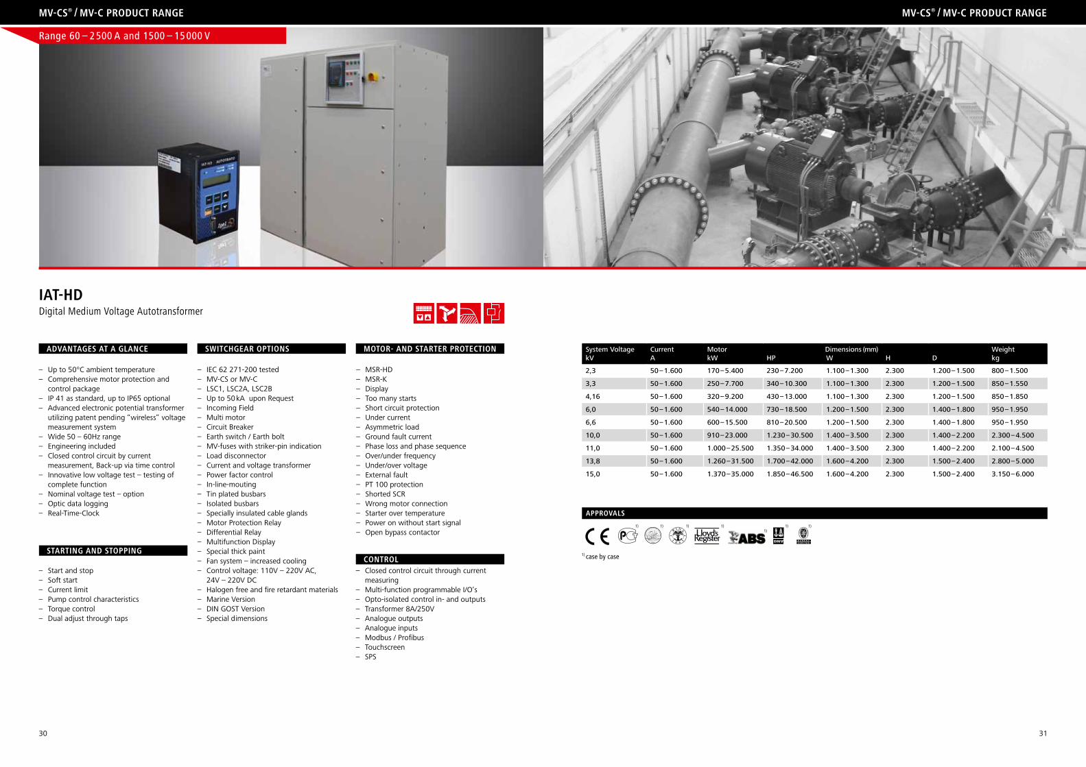
iat-hDDigital Medium Voltage Autotransformer
system voltage Current motor Dimensions (mm) Weightkv a kW hp W h D kg
2,3 50 – 1.600 170 – 5.400 230 – 7.200 1.100 – 1.300 2.300 1.200 – 1.500 800 – 1.500
3,3 50 – 1.600 250 – 7.700 340 – 10.300 1.100 – 1.300 2.300 1.200 – 1.500 850 – 1.550
4,16 50 – 1.600 320 – 9.200 430 – 13.000 1.100 – 1.300 2.300 1.200 – 1.500 850 – 1.850
6,0 50 – 1.600 540 – 14.000 730 – 18.500 1.200 – 1.500 2.300 1.400 – 1.800 950 – 1.950
6,6 50 – 1.600 600 – 15.500 810 – 20.500 1.200 – 1.500 2.300 1.400 – 1.800 950 – 1.950
10,0 50 – 1.600 910 – 23.000 1.230 – 30.500 1.400 – 3.500 2.300 1.400 – 2.200 2.300 – 4.500
11,0 50 – 1.600 1.000 – 25.500 1.350 – 34.000 1.400 – 3.500 2.300 1.400 – 2.200 2.100 – 4.500
13,8 50 – 1.600 1.260 – 31.500 1.700 – 42.000 1.600 – 4.200 2.300 1.500 – 2.400 2.800 – 5.000
15,0 50 – 1.600 1.370 – 35.000 1.850 – 46.500 1.600 – 4.200 2.300 1.500 – 2.400 3.150 – 6.000
Range 60 – 2 500 A and 1500 – 15 000 V
1)1) 1)1)1)1)1)
approvals
1) case by case
Mv-cs® / Mv-c proDuct range Mv-cs® / Mv-c proDuct range
32 33
– Up to 50°C ambient temperature– Comprehensive motor protection and control package– IP 41 as standard, up to IP65 optional– Advanced electronic potential transformer utilizing patent pending “wireless” voltage measurement system– Wide 50 – 60Hz range – Engineering included– Closed control circuit by current measurement, Back-up via time control– Innovative low voltage test – testing of complete function– Nominal voltage test – option– Optic data logging– Real-Time-Clock
– IEC 62 271-200 tested– MV-CS or MV-C– LSC1, LSC2A, LSC2B– Up to 50kA upon request– Incoming field– Circuit Breaker– Earth switch / Earth bolt– MV-fuses with striker-pin indication– Load disconnector– Current and voltage transformer – In-line-mouting – Tin plated busbars – Isolated busbars – Specially insulated cable glands– Multifunction Display– Special thick paint– Fan system – increased cooling– Control voltage: 110V – 220V AC, 24V – 220V DC– Halogen free and fire retardant materials– Marine Version– DIN GOST Version – Special Dimensions
– TSR-K– Display– Too many starts– Short circuit protection– Under current– Phase loss and phase sequence– Over/under frequency– Under/over voltage– External fault– Pt 100 protection– Starter short circuit – Power on without start signal– Open bypass contactor
– Multi-function programmable I/O’s Current limit – Opto-isolated control in- and outputs– Transformer 8A/250V – Modbus / Profibus– Touchscreen– SPS
– Start and Stopp– Current limit
control
Motor- anD starter protection sWitchgear options aDvantages at a glance
starting anD stopping
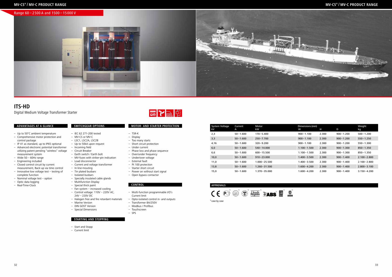
its-hDDigital Medium Voltage Transformer Starter
system voltage Current motor Dimensions (mm) Weightkv a kW W h D kg
2,3 50 – 1.600 170 – 5.400 900 – 1.100 2.300 900 – 1.200 500 – 1.200
3,3 50 – 1.600 250 – 7.700 900 – 1.100 2.300 900 – 1.200 550 – 1.250
4,16 50 – 1.600 320 – 9.200 900 – 1.100 2.300 900 – 1.200 550 – 1.300
6,0 50 – 1.600 540 – 14.000 1.100 – 1.500 2.300 900 – 1.300 850 – 1.350
6,6 50 – 1.600 600 – 15.500 1.100 – 1.500 2.300 900 – 1.300 850 – 1.350
10,0 50 – 1.600 910 – 23.000 1.400 – 3.500 2.300 900 – 1.400 2.100 – 2.800
11,0 50 – 1.600 1.000 – 25.500 1.400 – 3.500 2.300 900 – 1.400 2.100 – 2.800
13,8 50 – 1.600 1.260 – 31.500 1.600 – 4.200 2.300 900 – 1.400 2.800 – 3.100
15,0 50 – 1.600 1.370 – 35.000 1.600 – 4.200 2.300 900 – 1.400 3.150 – 4.200
Range 60 – 2 500 A and 1500 – 15 000 V
1)1) 1)1)1)1)1)
approvals
1) case by case
Mv-cs® / Mv-c proDuct range Mv-cs® / Mv-c proDuct range
34 35
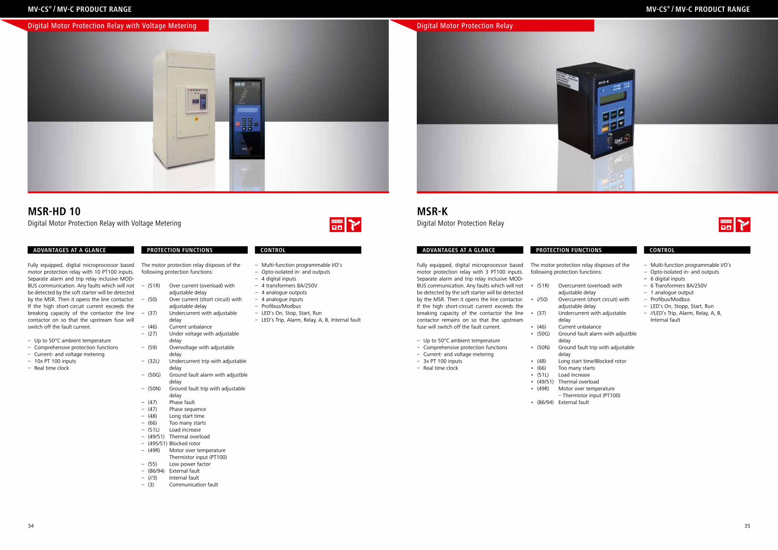
Fully equipped, digital microprocessor based motor protection relay with 10 PT100 inputs. Separate alarm and trip relay inclusive MOD-BUS communication. Any faults which will not be detected by the soft starter will be detected by the MSR. Then it opens the line contactor. If the high short-circuit current exceeds the breaking capacity of the contactor the line contactor on so that the upstream fuse will switch off the fault current.
– Up to 50°C ambient temperature– Comprehensive protection functions– Current- and voltage metering– 10x PT 100 inputs– Real time clock
The motor protection relay disposes of the following protection functions:
– (51R) Over current (overload) with adjustable delay– (50) Over current (short circuit) with adjustable delay– (37) Undercurrent with adjustable delay– (46) Current unbalance– (27) Under voltage with adjustable delay– (59) Overvoltage with adjustable delay– (32L) Undercurrent trip with adjustable delay– (50G) Ground fault alarm with adjustble delay– (50N) Ground fault trip with adjustable delay– (47) Phase fault– (47) Phase sequence– (48) Long start time– (66) Too many starts– (51L) Load increase– (49/51) Thermal overload– (49S/51) Blocked rotor– (49R) Motor over temperature Thermistor input (PT100) – (55) Low power factor– (86/94) External fault– (//3) Internal fault– (3) Communication fault
– Multi-function programmable I/O’s – Opto-isolated in- and outputs– 4 digital inputs– 4 transformers 8A/250V– 4 analogue outputs– 4 analogue inputs– Profibus/Modbus– LED’s On, Stop, Start, Run– LED’s Trip, Alarm, Relay, A, B, Internal fault
Mv-cs® / Mv-c proDuct range Mv-cs® / Mv-c proDuct range
aDvantages at a glance protection Functions control
Msr-hD 10Digital Motor Protection Relay with Voltage Metering
Fully equipped, digital microprocessor based motor protection relay with 3 PT100 inputs. Separate alarm and trip relay inclusive MOD-BUS communication. Any faults which will not be detected by the soft starter will be detected by the MSR. Then it opens the line contactor. If the high short-circuit current exceeds the breaking capacity of the contactor the line contactor remains on so that the upstream fuse will switch off the fault current.
– Up to 50°C ambient temperature– Comprehensive protection functions– Current- and voltage metering– 3x PT 100 inputs– Real time clock
The motor protection relay disposes of the following protection functions:
• (51R) Overcurrent(overload)with adjustable delay• (/50) Overcurrent(shortcircuit)with adjustable delay• (37) Undercurrentwithadjustable delay• (46) Currentunbalance• (50G) Groundfaultalarmwithadjustble delay• (50N) Groundfaulttripwithadjustable delay• (48) Longstarttime/Blockedrotor• (66) Toomanystarts• (51L) Loadincrease• (49/51) Thermaloverload• (49R) Motorovertemperature – Thermistor input (PT100) • (86/94) Externalfault
– Multi-function programmable I/O’s – Opto-isolated in- and outputs– 6 digital inputs– 6 Transformers 8A/250V– 1 analogue output– Profibus/Modbus– LED’s On, Stopp, Start, Run– //LED’s Trip, Alarm, Relay, A, B, Internal fault
aDvantages at a glance protection Functions control
Msr-KDigital Motor Protection Relay
Digital Motor Protection Relay with Voltage Metering Digital Motor Protection Relay
36 37
operating conDitions, insulation level, loaD level, internal arc QualiFication, protection classes
engineering engineering
cable connection, Delivery conDition, DiMensions anD installation
OPERATIONAL CONDITIONS
normal operating conditionsThe IGEL® Electric switchgears may be installed under normal opera-ting conditions as indoor-switchgears according to IEC 60594. The following limits have to be adhered to:Ambient temperature:– Maximum + 50°C– Maximum 24-hours average value + 45°C– Minimum value (according to indoor classification) -5°C– The installation elevation must be ≤ 1000 m above sea level.
CABLE CONNECTION
DIMENSION AND INSTALLATION – Mv-cs
The switchgear panels of IGEL® Electric may be supplied equipped with different cable connections. The dimensions of the single switchgear panels are depending on the product specific requirements:
switchgear panel up to 13,8 kv
Cable entry MV-CS MV-C MV-C ME MV-C-MECFrom top x x x xFrom bottom x x x x Cable exitFrom top x x x xFrom bottom x x x x
Important notice:Should the cable connection not be a standard version, please contact the producer in advance in order to discuss the details and prepare the production accordingly.
DELIVERY CONDITION
Upon delivery the IGEL® Electric switchgear panels are factory-assem-bled, the withdraw units are inserted and the doors are locked so that the switchgears are in operation position. At the factory the order conformity of the switchgear panels will be checked. Furthermore, a routine control according to IEC 62271-200 as well as a test of functionality and structure will be done. The busbar systems are only installed in switchgear panels with ≤ 3 panels.
The material for the busbars, the fixation and accessories will be pa-cked separately and are enclosed to the delivery. The busbars have a flat diameter and are consisting of copper, delivered in section parts which reach from panel to panel. Special fixing elements are not needed.
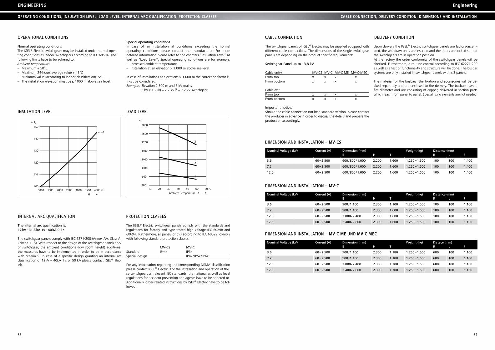
special operating conditionsIn case of an installation at conditions exceeding the normal operating conditions please contact the manufacturer. For more detailed information please refer to the chapters “Insulation Level” as well as “Load Level”. Special operating conditions are for example:– Increased ambient temperature– Installation at an elevation > 1.000 m above sea-level
In case of installations at elevations ≥ 1.000 m the correction factor k must be considered.Example: Elevation 2.500 m and 6 kV mains 6 kV x 1.2 (k) = 7.2 kV → = 7.2 kV switchgear
INSULATION LEVEL LOAD LEVEL
3000
2600
2200
1800
1400
1000
600
20010 20 30 40 50 60 70 °C
I
t
1
2
3
1,50
1,40
1,30
1,20
1,10
1,001000 1500 2000 2500 3000 3500 4000 m
m = 1
Ka
H
INTERNAL ARC QUALIFICATION
The internal arc qualification is: 12 kv – 31,5 ka 1s - 40 ka 0.5 s
The switchgear panels comply with IEC 6271-200 (Annex AA, Class A, Criteria 1– 5). With respect to the design of the switchgear panels and/or switchgear, the ambient conditions (low room height) additional the measures have to be implemented in order to be in accordance with criteria 5. In case of a specific design granting an internal arc classification of 12kV – 40kA 1 s or 50 kA please contact IGEL® Elec-tric.
PROTECTION CLASSES
The IGEL® Electric switchgear panels comply with the standards and regulations for factory and type tested high voltage IEC 60298 and 60694. Furthermore, all panels of this according to IEC 60529, comply with following standard protection classes:
mv-Cs mv-C Standard IP-4x IP3x Special design –––– IP4x / IP5x / IP6x
For any information regarding the corresponding NEMA classification please contact IGEL® Electric. For the installation and operation of the-se switchgears all relevant IEC standards, the national as well as local regulations for accident prevention and agents have to be adhered to. Additionally, order-related instructions by IGEL® Electric have to be fol-lowed.
nominal voltage (kv) Current (a) Dimension (mm) Weight (kg) Distance (mm)b h T r L F
3,6 60 – 2.500 600 / 800 / 1.000 2.200 1.600 1.250 – 1.500 100 100 1.400
7,2 60 – 2.500 600 / 800 / 1.000 2.200 1.600 1.250 – 1.500 100 100 1.400
12,0 60 – 2.500 600 / 800 / 1.000 2.200 1.600 1.250 – 1.500 100 100 1.400
DIMENSION AND INSTALLATION – Mv-c
nominal voltage (kv) Current (a) Dimension (mm) Weight (kg) Distance (mm)b h T r L F
3,6 60 – 2.500 900 / 1.100 2.300 1.100 1.250 – 1.500 100 100 1.100
7,2 60 – 2.500 900 / 1.100 2.300 1.600 1.250 – 1.500 100 100 1.100
12,0 60 – 2.500 2.000 / 2.400 2.300 1.600 1.250 – 1.500 100 100 1.100
17,5 60 – 2.500 2.400 / 2.800 2.300 1.600 1.250 – 1.500 100 100 1.100
DIMENSION AND INSTALLATION – Mv-c Me UND Mv-c Mec
nominal voltage (kv) Current (a) Dimension (mm) Weight (kg) Distace (mm)b h T r L F
3,6 60 – 2.500 900 / 1.100 2.300 1.180 1.250 – 1.500 600 100 1.100
7,2 60 – 2.500 900 / 1.100 2.300 1.180 1.250 – 1.500 600 100 1.100
12,0 60 – 2.500 2.000 / 2.400 2.300 1.700 1.250 – 1.500 600 100 1.100
17,5 60 – 2.500 2.400 / 2.800 2.300 1.700 1.250 – 1.500 600 100 1.100
38 39
SwITChGEAR
COMPONENTS
TRANSFORMER
IP RATING
INSULATION
INSTALLATION
SEMICONDUCTOR
MV-CS / MV-C
Circuit Breaker
Earthing Switch
Load Break Switch
Load Break Switch / Fuse Combination
HH-Fuses
Soft Starter
Voltage Indicator
Voltage Transformer
Current Transformer
–
–
–
Soft Starter
IEC 60 694
IEC 62 271-200
IEC 62 271-100
IEC 62 271-102
IEC 60 265-1
IEC 62 271-105
IEC 60 282
IEC 60 270
IEC 61 243-5
IEC 60 044-2
IEC 60 044-1
IEC 60 529
IEC 60 071
IEC 61 936-1
IEC 60 747-5-5
VDE 0670-1000
VDE 0671-200
VDE 0671-100
VDE 0671-102
VDE 0670-301
VDE 0671-105
VDE 0670-4
VDE 0682-415
VDE 0414-2
VDE 0414-1
VDE 0470-1
VDE 0111
VDE 0101
VDE 0884-5
EN 60 694
EN 62 271-200
IEC 62 271-100
IEC 62 271-102
IEC 60 265-1
IEC 62 271-105
IEC 60 282
EN 50 178
IEC 61 243-5
IEC 60 044-2
IEC 60 044-1
IEC 60 529
IEC 60 071
IEC 61 936-1
EN 60 74755
engineering
STANDARDS
MV-CS
MV-C
CERTIFIED QUALITY
enginnering
certiFicatesstanDarDs, rateD values Mv-cs / Mv-c
The IGEL® Electric switchgear complies to the present standards and regulations of the IEC type test. According to the harmonization treaty of the EC, the national standards conform to the IEC standards.
rating subjects
rated voltage 7,2 kv 12 kv
rated Frequency 50 hz / 60 hz 50 hz / 60 hz
rated Current 400 – 2.500 a 400 – 2.500 a
rated protection Class Ip 4x Ip 4x
rated short-duration power-frequency withstand voltage
20 kv 28 kv
rated lightning impulsewithstand voltage
60 kv 75 kv
rated short-time inrush current 1 s 16 – 31,5 ka 16 – 31,5 ka
rated peak withstand current 52 – 82 ka 52 – 82 ka
Internal arc Qualification IaC a FLr Isc ≤ 31,5 ka, t = 1 s
Category of availability LsC 2b LsC 2b
partition class pI /pm pI /pm
rating subjects
rated voltage 3,6 kv 7,2 kv 12 kv 17,5 kv
rated Frequency 50 hz / 60 hz 50 hz / 60 hz 50 hz / 60 hz 50 hz / 60 hz
rated Current 60 – 2.500 a 60 – 2.500 a 60 – 2.500 a 60 – 2.500 a
rated protection Class Ip 31 – Ip 65 Ip 31 – Ip 65 Ip 31 – Ip 65 Ip 31 – Ip 65
rated short-duration power-frequency withstand voltage
20 kv 20 kv 28 kv 38 kv
rated lightning impulsewithstand voltage
40 kv 60 kv 75 kv 95 kv
rated short-time inrush current 1 s 16 – 40 ka / 50 ka* 16 – 40 ka / 50 ka* 16 – 40 ka / 50 ka* 16 – 40 ka / 50 ka*
rated peak withstand current 52 – 100 ka / 125 ka* 52 – 100 ka / 125 ka* 52 – 100 ka / 125 ka* 52 – 100 ka / 125 ka*
Internal arc Qualification IaC a FL(r) Isc ≤ 40 ka, t = 1 s
Category of availability LsC 1 / LsC 2a / LsC 2b LsC 1 / LsC 2a / LsC 2b LsC 1 / LsC 2a / LsC 2b LsC1 / LsC ka / LsC2b
partition class pI /pm pI /pm pI /pm pI /pm
In times during which every small trading workshop is putting his qua-lity manual online there are significant differences in respect of the concept “quality”. In many companies this concept is reduced to the introduction of the ISO 9001 certification. Basically, the ISO 9001 certi-fication is only describing internal processes and by this a regulated and quality orientated production should be supported. The product design as well as the single production steps and techniques are not changed.
›Better is the enemy of good‹
This best describes the quality philosophy at the IGEL® Electric Com-pany. Our products as well as our production are regularly subject to external tests, approvals and audits and improved upon constantly. The main part of our production is yearly audited by the VDE as well as several major customers e.g. the world’s largest Electric group. For our company these audits are not seen as duties but as chances. Because of their extensive experience in quality management the auditors very often supported us to optimize our production processes.
Our product quality is based on highest quality demands. During their development our products have to pass all standard type tests accor-ding to the valid IEC standards and demands. These tests confirm the quality orientated development strategy. Especially the destroying tests (internal arc test) provide additional indications for the product opti-mization. Additionally to the routine tests our products are regularly tested in single approvals. Some examples of single approvals:
– TÜv, approval for the application in ex-environments– GL, Lr, abs, Dnv, bv …, approval for the shipbuilding– GOsT, CCC … , country-specific approvals– vds approval for the application in fire-extinguishing systems
Especially the single approvals with their different technical specifica-tions and set of rules present a special challenge for our engineers. Every time the product design must be checked and – if necessary – adjusted in respect of its conformity to the demanded specification. The fields of application such as shipbuilding, ex-area and fire-extingu-ishing systems show which quality criteria have been applied for our products.
As a medium-sized company producing moderate quantities a wide range of products is not convenient in respect of production technique as well as purchase reasons. Therefore, all design amendments due to new quality criteria will be automatically adopted in our serial produc-tion. This is the reason why each of our customers is profiting from our experiences with the worldwide most demanding testing institutes.
* upon request
40
Industrieweg 13 –1548324 SendenhorstGermany
Fon: +49 (0) 25 26 93 89 - 0Fax: +49 (0) 25 26 93 89 - 22
E-Mail: [email protected]
igel® electric gmbh
Copyright IGEL® Electric
Edition: 03.2012