Embed Size (px)
Citation preview
MP2100A SeriesBERTWave
Product Brochure
2 Product Brochure
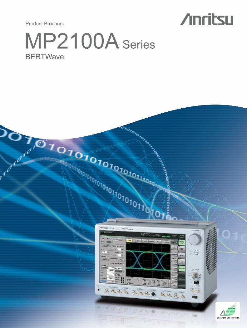
Eye/Pulse ScopeBERTMP2100A BERTWave
MP2101A BERTWave PE
MP2102A BERTWave SS
Slim All-in-One Instrument for BER and Eye-pattern Analysis
MP2100A series BERTWaveThe MP2100A series BERTWave cuts measurement times and assures signal integrity. Customers can tailor the configuration according to usage.
MP2100A BERTWaveAll-in-one instrument supporting simultaneous BER measurements and Eye-pattern analysis
MP2101A BERTWave PEBER tester supporting 125 Mbit/s to 12.5 Gbit/s
MP2102A BERTWave SSEye/Pulse pattern tester supporting high-speed mask tests
Cuts Measurement Times and Raises Productivity The rapid spread of the Internet and increases in network transmission capacity are driving development and manufacturing of FTTx and 10-Gbit Ethernet devices. As a result, R&D into high-speed transmission technologies and manufacturing of high-speed devices are both progressing at a fast pace. To assure the integrity of signals passing via these high-speed devices, the Bit Error Rate (BER) and Eye-pattern are measured using a BERT and sampling scope. The all-in-one MP2100A series BERTWave supporting simultaneous BER and Eye-pattern measurements is ideal for both R&D and manufacturing tests because it increases efficiency and cuts measurement costs by eliminating time-consuming setup.
Supports Electrical and Optical InterfacesWide Operation Frequency Range
Signal Integrity Analysis
Various Analysis Functions
Clock RecoverySimultaneous 2-channel BER Measurements
High-speed Remote TestsAll-in-one BER and Eye-pattern Measurements
High-speed Mask Tests
Cuts Measurement Times
Easy Operability, Flash Disk Drive, and Eco-friendlyFlexible Measurement
Low Equipment and Running Costs
BERT
Eye/Pulse Scope
Product Brochure 3
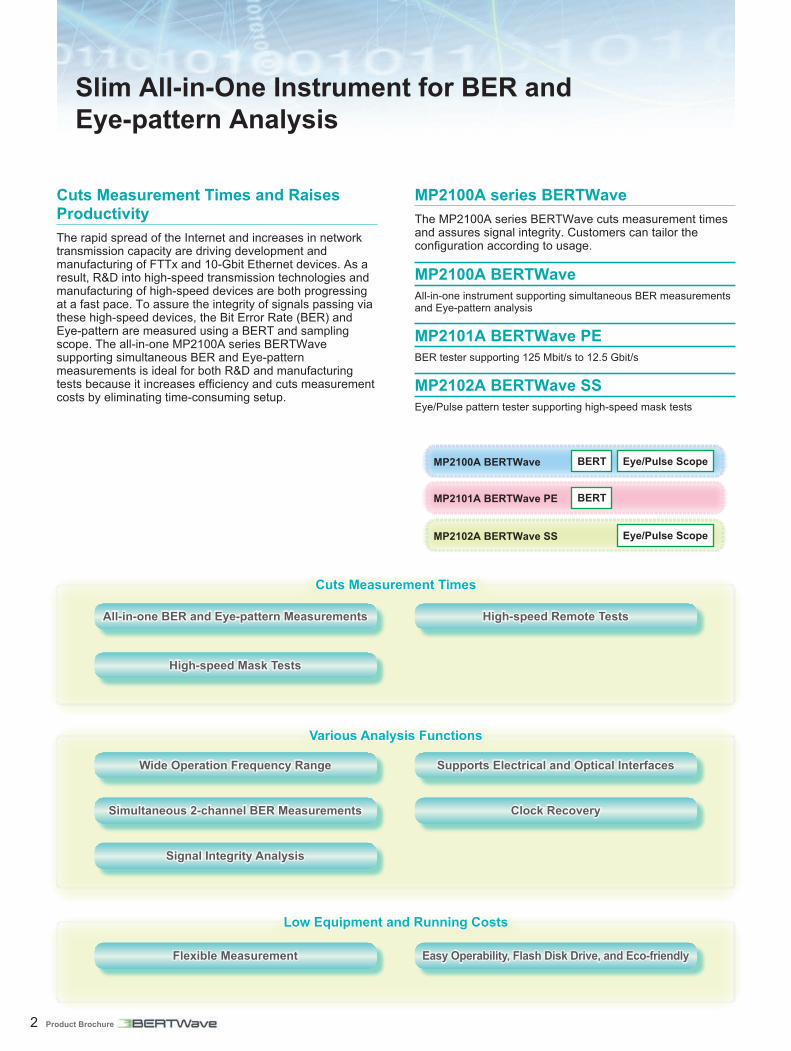
All-in-one BER and Eye-pattern MeasurementsSimultaneous BER and Eye/Pulse Scope measurements using an all-in-one tester halve investment costs and cut measurement times. The tracking function supports easy BERT and Eye/Pulse Scope settings.
High-speed Remote Tests The built-in remote high-speed mode supports mix remote functions for batch processing multiple commands and cuts BER measurement times by 30%* to 10 ms.*: Compared to MP1761C/62C
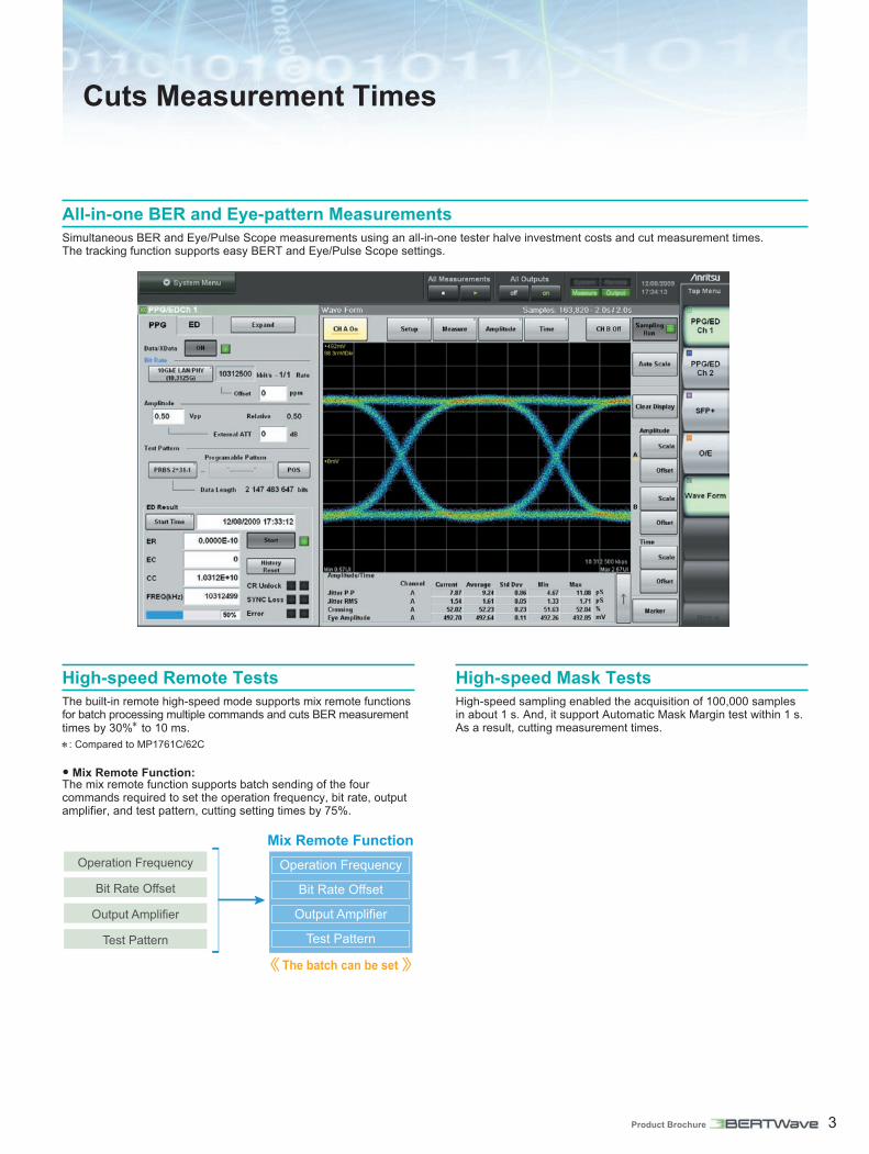
• Mix Remote Function:The mix remote function supports batch sending of the four commands required to set the operation frequency, bit rate, output amplifier, and test pattern, cutting setting times by 75%.
Cuts Measurement Times
High-speed Mask Tests High-speed sampling enabled the acquisition of 100,000 samples in about 1 s. And, it support Automatic Mask Margin test within 1 s. As a result, cutting measurement times.

4 Product Brochure
Insertion / OmissionThis can check how signal is involved.
Insertion: Change of 0→1Omission: Change of 1→0
Clock Recovery ED Clock Recovery Function (Standard):This is for inputting data signals and performing BER analysis without an external clock.
• 4 Gbit/s to 6.25 Gbit/s, 8 Gbit/s to 12.5 Gbit/sThis have been using the trigger of Scope.
Eye/Pulse Pattern Clock Recovery Function (Option-055):• 8.5 GHz to 12.5 GHz, 0.1 GHz to 2.7 GHzThis supports evaluation of characteristics of long-distance transmissions and equipment without clock output.
Signal Integrity Analysis The Eye/Pulse Scope supporting DC to 25 GHz offers signal integrity analysis using a variety of applications.
Time and Amplifier Tests
These tests supports measurement of 0 and 1 levels, SNR, Eye crosspoint ratio, Eye amplification, Eye height, Eye width, Jitter p-p values, Jitter RMS, Extinction ratio, Rise and Fall times, Duty cycle distortion, and Average power and OMA.In addition, the high-accuracy extinction ratio measurements close to ideal values are perfect for confirming the characteristics of optical modules.
Supports Electrical and Optical Interfaces One MP2100A supports both electrical and optical interfaces for performing simultaneous TRx evaluations of optical modules, cutting measurement times.
Wide Operation Frequency Range The BERT function supports bit rate from 125 Mbit/s to 12.5 Gbit/s (with Option-090) for evaluating devices and application supporting STM-1, 10 GFC and etc…
Various Analysis Functions
Simultaneous 2-channel BER MeasurementsExpansion of the BERT to 2 channels supports easy simultaneous TRx measurements, crosstalk tests and confirmation of adjacent lane interference.

Product Brochure 5
Eye Mask/Mask Margin Tests
Eye Mask and Mask Margin tests confirm product margin against standards to improve yield.
• Automatic measurement within 1 s• Supporting real time Mask Margin test
Mask Adjust
The Eye mask area can be adjusted either automatically or manually. As a result, the waveform mask can be measured without restrictions on the time axis.*: Can set when Align Method is User Defined.
Change Specified Mask Area
The specified mask area for the target application or user mask can be changed. Consequently, positions in the open Eye where the mask margin is maximum and minimum can be evaluated.
Mask Area Restriction On(45 degrees, 0.1UI)
Ideal Extinction Ratio Measurements
1. Ideal Bessel filtersBessel filters with the ideal frequency characteristics support high-accuracy extinction ratio measurement results.
2. High-accuracy results close to true value
Calibration using the reference light source holds error to less than ±0.05 dB (typ.).
3. Correction functionCorrection of the measured extinction ratio assures correlation with other instruments.
Correction Value Input Display
Frequency Characteristics (fc = 7.6 GHz)
High-accuracy Extinction Ratio Measurements Close to Ideal Values
Frequency [GHz]
S21
[dB
]
IEEE 802.3Anritsu's Bessel Filter

6 Product Brochure
Reference Trace Function
This function saves measured waveforms to compare saved data with waveforms being measured.
Skew Function
The built-in skew function moves the waveform on the time axis to adjust the waveform position.Therefore, this function can adjust the phase between channels of differential signal.
Histogram
Measuring averages, standard deviation and scatter of data in a specified area supports waveform data component analysis and troubleshooting.
Flexible MeasurementsEquipment costs are cut by choosing a custom configuration from the BERTWave, BERTWave PE, and BERTWave SS range of tailored measurement solutions.
• BERTWave : BER and Eye/Pulse measurements• BERTWave PE : BER measurement• BERTWave SS : Eye/Pulse measurement
Easy Operability, Flash Disk Drive, and Eco-designImproved Operability• PPG/ED simple design• 12.1-inch display• Intuitive GUI with touch panel
High Reliability• The flash drive makes hard-disk crashes a thing of the past.
Eco-design• 18-cm deep compact design• Dimensions: 341 (W) × 221 (H) × 180 (D) mm• Lightweight (7 kg Max.)• Low power consumption (300 VA Max.)
Low Cost and Eco-friendly Design

Product Brochure 7
Cuts Measurement Times
Simultaneous BER and Eye/Pulse Scope measurements using the all-in-one tester halve investment costs and cut measurement times. Use with the MP2100A BERTWave and MS9740A Optical Spectrum Analyzer cuts optical module measurement times.
• Simultaneous TRx MeasurementsOne MP2100A supports both electrical and optical interfaces for performing simultaneous TRx evaluations of optical modules, cutting measurement times.
• High-speed Remote TestsThe built-in remote high-speed mode supports mixed remote functions for batch processing multiple commands and cuts BER measurement times by 30% to 10 ms.
• High-speed Mask TestsHigh-speed sampling supports fast mask tests in about 12 s*, cutting measurement times.*: Typical value when capturing 1 x 10⁶ samples at bit rate of 10.3125 Gbit/s with PRBS31 test pattern, back-to-back
MP2100A Series BERTWave
MP2100A BERTWave
Optical Module Evaluations
Optical Transceiver Measurement Items
Measurement Items MP2100A BERTWave
MS9740A Optical
Spectrum Analyzer
Tx
Data Rate Tolerance √Center Wavelength √Side Mode Suppression Ratio √Average Optical Output Power (Min./Max.) √ √Extinction Ratio √Mask Test √
Rx Input Sensitivity (10–12) √*
*: Programmable optical attenuator is needed.

8 Product Brochure
Simultaneous TRx Measurements and Crosstalk Tests
Expansion of the MP2101A BERTWave PE to a 2-channel BERT supports simultaneous TRx measurements and crosstalk tests for high-speed, multilane active optical cables to help reduce crosstalk. Moreover, selecting the MP2100A BERTWave supports simultaneous Eye-pattern analysis to further improve manufacturing yields.
• Simultaneous 2-channel BER MeasurementsExpansion of the BERT to 2 channels supports easy simultaneous TRx measurements and confirms crosstalk tests.
• All-in-one BER and Eye-pattern*Simultaneous BER measurements and Eye-pattern analysis using an all-in-one tester does not require a separate BERT and sampling scope, halving equipment costs.
• Wide Operating Frequency Range*The BERT function supports bit rate from 125 Mbit/s to 12.5 Gbit/s (with Option-090) for evaluating devices and application supporting STM-1, 10 GFC and etc…*: The MP2100A BERTWave supports Eye-pattern analysis and Eye mask tests.
MP2100A BERTWave/MP2101A BERTWave PE
Active Optical Cable Evaluation
MP2102A BERTWave SS
Evaluation of Transmission Equipment Physical Layer
Physical Layer Evaluation
The MP2102A BERTWave SS clock recovery function eliminates the need for a trigger source when evaluating optical output characteristics, and the full range of mask patterns makes the MP2102A ideal for both evaluating the physical layer of equipment supporting various 2G, 4G, and 8GFC applications, and for testing optical transceivers at acceptance inspection.
• Clock RecoveryThe Eye/Pulse pattern Clock recovery (Option-055) function supports rates of 8.5 GHz to 12.5 GHz and 0.1 GHz to 2.7 GHz to perform mask tests for most applications.
• High-speed Mask TestsHigh-speed sampling supports fast mask tests in about 12 s*, cutting measurement times.*: Typical value when capturing 1 × 10⁶ samples at bit rate of 10.3125 Gbit/s with PRBS31 test pattern, back-to-back

Product Brochure 9
MP2100A-001 MP2100A-003 MP2101A-011 MP2101A-012 MP2102A-021 MP2102A-023
MP2100A Series BERTWave Composition
MP2100A BERTWave MP2102A BERTWave SSMP2101A BERTWave PE
Block Diagram
Interface ListInterface
MP2100A BERTWave MP2101A BERTWave PE MP2102A BERTWave SSMP2100A-001 MP2100A-003 MP2101A-011 MP2101A-012 MP2102A-021 MP2102A-023
2 Output (Electrical Data1, xData1) √ √ √ √2 Input (Electrical Data1/Scope1, Electrical xData1/Scope2) √ √2 Input (Electrical Data1/Scope1, Optical Data2/Scope2) √2 Input (Electrical Data1, xData1) √ √2 Input (Electrical Scope1, Scope2) √2 Input (Electrical Scope1, Optical Scope2) √
Additional Interface
2 Output (Electrical Data1, xData1) √*1 √*1 √2 Input (Electrical Data1, xData1) √*1 √*1 √XFP Slot √*2 √*2 √*2 √*2
SFP+ Slot √*3 √*3 √*3 √*3
Function ListInterface
MP2100A BERTWave MP2101A BERTWave PE MP2102A BERTWave SSMP2100A-001 MP2100A-003 MP2101A-011 MP2101A-012 MP2102A-021 MP2102A-023
Crosstalk tests √*1 √*1 √Optical Module Simultaneous TRx measurements (XFP) √*1, *4
1ch BER measurement √ √ √ √2ch BER measurement √*1 √*1 √Electrical integrity of signals tests- Time and Amplitude Tests- Histogram Test- Eye Mask/Mask Margin Tests
√ √ √ √
Optical integrity of signals tests- Time and Amplitude Tests- Histogram Test- Eye Mask/Mask Margin Tests
√ √
*1: Option-005 Selected*2: Option-050 Selected*3: Option-051 Selected*4: Option-050 or Option-051 Selected
10 Product Brochure
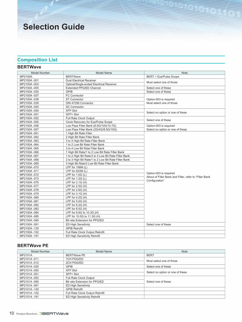
Composition ListBERTWave
Model Number Model Name NoteMP2100A BERTWave BERT + Eye/Pulse ScopeMP2100A -001 Dual Electrical Receiver Must select one of thoseMP2100A -003 Optical/Single-ended Electrical ReceiverMP2100A -005 Extended PPG/ED Channel Select one of theseMP2100A -030 GPIB Select one of theseMP2100A -037 FC Connector
Option-003 is required Must select one of those
MP2100A -038 ST ConnectorMP2100A -039 DIN 47256 ConnectorMP2100A -040 SC ConnectorMP2100A -050 XFP Slot Select no option or one of theseMP2100A -051 SFP+ SlotMP2100A -052 Full Rate Clock Output Select one of theseMP2100A -055 Clock Recovery for Eye/Pulse ScopeMP2100A -056 Low Pass Filter Bank (8.5G/10G/10.7G) Option-003 is required
Select no option or one of theseMP2100A -057 Low Pass Filter Bank (2G/4G/8.5G/10G)MP2100A -061 1 High Bit Rate Filter
Option-003 is required About of Filter Bank and Filter, refer to “Filter Bank Configuration”
MP2100A -062 2 High Bit Rate Filter BankMP2100A -063 3 to 4 High Bit Rate Filter BankMP2100A -064 1 to 2 Low Bit Rate Filter BankMP2100A -065 3 to 4 Low Bit Rate Filter BankMP2100A -066 1 High Bit Rate/1 to 2 Low Bit Rate Filter BankMP2100A -067 1 to 2 High Bit Rate/3 to 4 Low Bit Rate Filter BankMP2100A -068 2 to 3 High Bit Rate/1 to 2 Low Bit Rate Filter BankMP2100A -069 3 High Bit Rate/3 Low Bit Rate Filter BankMP2100A -070 LPF for 156M (L)MP2100A -071 LPF for 622M (L)MP2100A -072 LPF for 1.0G (L)MP2100A -073 LPF for 1.2G (L)MP2100A -076 LPF for 2.1G (H)MP2100A -077 LPF for 2.5G (H)MP2100A -078 LPF for 2.6G (H)MP2100A -079 LPF for 3.1G (H)MP2100A -080 LPF for 4.2G (H)MP2100A -081 LPF for 5.0G (H)MP2100A -082 LPF for 6.2G (H)MP2100A -083 LPF for 8.5G (H)MP2100A -084 LPF for 9.9G to 10.3G (H)MP2100A -085 LPF for 10.5G to 11.3G (H)MP2100A -090 Bit rate Extension for PPG/EDMP2100A -091 ED High Sensitivity Select one of theseMP2100A -130 GPIB RetrofitMP2100A -152 Full Rate Clock Output RetrofitMP2100A -191 ED High Sensitivity Retrofit
BERTWave PEModel Number Model Name Note
MP2101A BERTWave PE BERTMP2101A -011 1CH PGG/ED Must select one of thoseMP2101A -012 2CH PGG/EDMP2101A -030 GPIB Select one of theseMP2101A -050 XFP Slot Select no option or one of theseMP2101A -051 SFP+ SlotMP2101A -052 Full Rate Clock Output
Select one of theseMP2101A -090 Bit rate Extension for PPG/EDMP2101A -091 ED High SensitivityMP2101A -130 GPIB RetrofitMP2101A -152 Full Rate Clock Output RetrofitMP2101A -191 ED High Sensitivity Retrofit
Selection Guide
Product Brochure 11
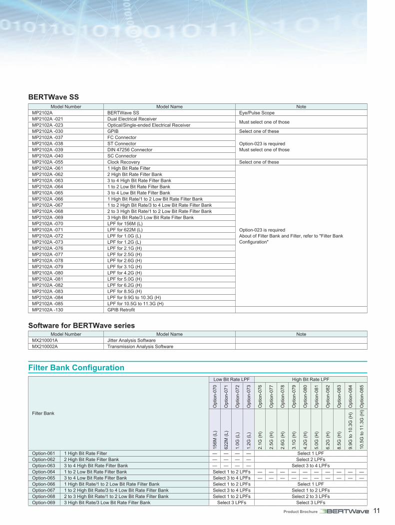
BERTWave SSModel Number Model Name Note
MP2102A BERTWave SS Eye/Pulse ScopeMP2102A -021 Dual Electrical Receiver Must select one of thoseMP2102A -023 Optical/Single-ended Electrical ReceiverMP2102A -030 GPIB Select one of theseMP2102A -037 FC Connector
Option-023 is required Must select one of those
MP2102A -038 ST ConnectorMP2102A -039 DIN 47256 ConnectorMP2102A -040 SC ConnectorMP2102A -055 Clock Recovery Select one of theseMP2102A -061 1 High Bit Rate Filter
Option-023 is required About of Filter Bank and Filter, refer to "Filter Bank Configuration"
MP2102A -062 2 High Bit Rate Filter BankMP2102A -063 3 to 4 High Bit Rate Filter BankMP2102A -064 1 to 2 Low Bit Rate Filter BankMP2102A -065 3 to 4 Low Bit Rate Filter BankMP2102A -066 1 High Bit Rate/1 to 2 Low Bit Rate Filter BankMP2102A -067 1 to 2 High Bit Rate/3 to 4 Low Bit Rate Filter BankMP2102A -068 2 to 3 High Bit Rate/1 to 2 Low Bit Rate Filter BankMP2102A -069 3 High Bit Rate/3 Low Bit Rate Filter BankMP2102A -070 LPF for 156M (L)MP2102A -071 LPF for 622M (L)MP2102A -072 LPF for 1.0G (L)MP2102A -073 LPF for 1.2G (L)MP2102A -076 LPF for 2.1G (H)MP2102A -077 LPF for 2.5G (H)MP2102A -078 LPF for 2.6G (H)MP2102A -079 LPF for 3.1G (H)MP2102A -080 LPF for 4.2G (H)MP2102A -081 LPF for 5.0G (H)MP2102A -082 LPF for 6.2G (H)MP2102A -083 LPF for 8.5G (H)MP2102A -084 LPF for 9.9G to 10.3G (H)MP2102A -085 LPF for 10.5G to 11.3G (H)MP2102A -130 GPIB Retrofit
Software for BERTWave seriesModel Number Model Name Note
MX210001A Jitter Analysis SoftwareMX210002A Transmission Analysis Software
Filter Bank Configuration
Filter Bank
Low Bit Rate LPF High Bit Rate LPF
Opt
ion-
070
Opt
ion-
071
Opt
ion-
072
Opt
ion-
073
Opt
ion-
076
Opt
ion-
077
Opt
ion-
078
Opt
ion-
079
Opt
ion-
080
Opt
ion-
081
Opt
ion-
082
Opt
ion-
083
Opt
ion-
084
Opt
ion-
085
156M
(L)
622M
(L)
1.0G
(L)
1.2G
(L)
2.1G
(H)
2.5G
(H)
2.6G
(H)
3.1G
(H)
4.2G
(H)
5.0G
(H)
6.2G
(H)
8.5G
(H)
9.9G
to 1
0.3G
(H)
10.5
G to
11.
3G (H
)
Option-061 1 High Bit Rate Filter — — — — Select 1 LPFOption-062 2 High Bit Rate Filter Bank — — — — Select 2 LPFsOption-063 3 to 4 High Bit Rate Filter Bank — — — — Select 3 to 4 LPFsOption-064 1 to 2 Low Bit Rate Filter Bank Select 1 to 2 LPFs — — — — — — — — — —Option-065 3 to 4 Low Bit Rate Filter Bank Select 3 to 4 LPFs — — — — — — — — — —Option-066 1 High Bit Rate/1 to 2 Low Bit Rate Filter Bank Select 1 to 2 LPFs Select 1 LPFOption-067 1 to 2 High Bit Rate/3 to 4 Low Bit Rate Filter Bank Select 3 to 4 LPFs Select 1 to 2 LPFsOption-068 2 to 3 High Bit Rate/1 to 2 Low Bit Rate Filter Bank Select 1 to 2 LPFs Select 2 to 3 LPFsOption-069 3 High Bit Rate/3 Low Bit Rate Filter Bank Select 3 LPFs Select 3 LPFs

12 Product Brochure
110
2
11
3
12
4
13
5
14
6
15
7
16
8
17
9
1819
1 Ground TerminalConnects antistatic wrist strap
2 Display12.1-inch touch panel
3 Rotary KnobChanges set value
4 Disk Access, Standby and Power Lamps5 Power Switch6 Optical Input Connector
Supported by MP2100A-003 and MP2102A-0237 Optical Transceiver Slot
Supports XFP modules when MP2100A/MP2101A-050 selected as well as SFP + module when MP2100A/MP2101A-051 selected
8 Optical Output Display LampWhen MP2100A/MP2101A-050 or MP2100A/MP2101A-051 selected
9 Optical Transceiver Received Signal Output TerminalWhen MP2100A/MP2101A-050 or MP2100A/MP2101A-051 selected
10 Optical Transceiver Transmitted Signal Input TerminalWhen MP2100A/MP2101A-050 or MP2100A/MP2101A-051 selected
11 USB Connector12 Error Detector CH2 Input Terminal
When MP2100A-005 or MP2101A-012 selected13 Pulse Pattern Generator CH2 Output Terminal
When MP2100A-005 or MP2101A-012 selected14 Error Detector CH1/Eye/Pulse Scope Input Terminal
A (in) and B (in) supported when MP2100A-001, MP2101A-011/012, or MP2102A-021 selected. A (in) supported when MP2100A-003 or MP2102A-023 selected
15 Pulse Pattern Generator CH1 Output TerminalWhen MP2100A or MP2101A selected
16 Clock Recovery Unit Output TerminalWhen MP2100A-055 or MP2102A-055 selected
17 Eye/Pulse Scope Trigger Input TerminalWhen MP2100A or MP2102A selected
18 Synchronized Pulse Output TerminalWhen MP2100A or MP2101A selected
19 Clock Input TerminalWhen MP2100A or MP2101A selected
Key Layout

Product Brochure 13
20
30
21
31
22
3223
24
25
26 27 28
29
20 10 MHz Clock InputWhen MP2100A or MP2101A selected
21 GPIB ConnectorWhen MP2100A/MP2101A/MP2102A-030 selected
22 Inlet
23 PS2 Mouse Port24 Serial Interface25 Ethernet Port26 Line Input27 Line Output28 Microphone Input29 USB Port30 Monitor Output (15 pins)31 Monitor Output (9 pins)/Serial Interface32 PS2 Keyboard Port
Rear
Left side

14 Product Brochure
MP2100A, MP2101A, MP2102A CommonInput Device Rotary Encoder, Touch Panel, Power SwitchLiquid-crystal Display 12.1 inch WXGA (1280 × 800)Remote Interface Ethernet, GPIB (Option-030)Circumjacent Connection VGA Output (SVGA), USB (5ports, Revision 2.0), Ethernet (2ports, 10/100/1000 BASE-T)OS Windows embedded standard 2009 (based on Windows XP SP3)Internal Memory Flash memory 8 GB (min.)Power Supply 100 V(ac) to 120 V(ac)/200 V(ac) to 240 V(ac) (100 V/200 V is unnecessary change.), 50 Hz/60 HzPower Consumption 300 VA (max.)
Temperature Range Operating: +5˚ to +40˚CStorage: –20˚ to +60˚C
Dimensions 341 (W) × 221.5 (H) × 180 (D) mm (Exclusive of surface projection)Mass 7 kg (max.) (With MP2100A-003 installing, Not contain other options)EMC EN61326-1, EN61000-3-2LVD EN61010-1
BERT• Common
External 10 MHz Input Connector Amplitude: 0.7 Vp-p to 2 Vp-p, AC coupledConnector: BNC connector, 50 Ω
External Ref Clock InputExternal 1/16 Clock InputAmplitude: 0.2 Vp-p to 1.5 Vp-p, AC coupledConnector: SMA connector, 50 Ω
Sync. Output
Output Level: VOL: –0.5 V to –0.3 V, VOH: –0.1 V to 0 V, 0.4 Vp-p (typ.)Connector: SMA connector, 50 Ω
Bit Rate Frequency Dividing Rate8.5G to 11.32G 1/8 PPG Clock, 1/16 PPG Clock, 1/64 PPG Clock, PPG Pattern Sync., 1/16 ED Clock
1/2 Rate 1/4 PPG Clock, 1/16 PPG Clock, 1/64 PPG Clock, PPG Pattern Sync., 1/4 ED Clock, 1/16 ED Clock
1/4 Rate 1/2 PPG Clock, 1/16 PPG Clock, PPG Pattern Sync.1/8 Rate 1/1 PPG Clock, PPG Pattern Sync.1/16 Rate 1/1 PPG Clock, PPG Pattern Sync.1/64 Rate 1/1 PPG Clock, PPG Pattern Sync.
• PPG
Operation Bit Rate
With MP2100A/MP2101A-090 Without MP2100A/MP2101A-090Variable bit-rate range (1 kbit/s step)
8 Gbit/s to 12.5 Gbit/sVariable bit-rate range (1 kbit/s step)
8.5 Gbit/s to 11.32 Gbit/s1/N bit-rate operation range
N=2: 4 Gbit/s to 6.25 Gbit/sN=4: 2 Gbit/s to 3.125 Gbit/sN=8: 1 Gbit/s to 1.5625 Gbit/sN=16: 500 Mbit/s to 781.25 Mbit/sN=32: 250 Mbit/s to 390.625 Mbit/sN=64: 125 Mbit/s to 195.312 Mbit/s
1/N bit-rate operation rangeN=2: 4.25 Gbit/s to 5.66 Gbit/sN=4: 2.125 Gbit/s to 2.83 Gbit/sN=8: 1.0625 Gbit/s to 1.415 Gbit/sN=16: 531.25 Mbit/s to 707.5 Mbit/sN=32: 265.625 Mbit/s to 353.75 Mbit/sN=64: 132.813 Mbit/s to 176.875 Mbit/s
Internal Reference Clock Accuracy ±10 ppmOffset Variability: ±100 ppm, 1 ppm step
Data Output
Data, xDataAmplitude: Variable 0.1 Vp-p to 0.8 Vp-p, 10 mV step, AC coupledTr/Tf: 25 ps (20 to 80%, typ.)Output Jitter: 3 ps rms (typ.)Connector: SMA connector, 50 Ω
Test Pattern PRBS: 27 – 1, 29 – 1, 215 – 1, 223 – 1, 231 – 1 (Invert ON/OFF)User Data: 1.3 Mbit/s (Editable Text File, Presence Sample File)
Error Addition Repeat, Single
Specifications

Product Brochure 15
● ED
Operation Bit Rate
With MP2100A/MP2101A-090 Without MP2100A/MP2101A-090Variable bit-rate range (1 kbit/s step)
8 Gbit/s to 12.5 Gbit/s
1/N bit-rate operation range*N=2: 4 Gbit/s to 6.25 Gbit/sN=4: 2 Gbit/s to 3.125 Gbit/sN=8: 1 Gbit/s to 1.5625 Gbit/sN=16: 500 Mbit/s to 781.25 Mbit/sN=32: 250 Mbit/s to 390.625 Mbit/sN=64: 125 Mbit/s to 195.312 Mbit/s
Variable bit-rate range (1 kbit/s step) 8.5 Gbit/s to 11.32 Gbit/s4.25 Gbit/s to 5.66 Gbit/s
Offset Capacity ±100 ppm
Electrical Data Input
Input Number: Data, xData, Single-ended or Differential (With MP2100A-001, MP2101A-011, MP2101A-012) Data, Single (With MP2100A-003)
Input Format: NRZ, Mark Ratio 50%Threshold: –0.085 V to +0.085 V, 1 mV stepConsecutive Identical Digit Tolerance: 72 bits (min.)Connector
MP2100A: K connector MP2101A: SMA connector
With MP2100A/MP2101A-090 Without MP2100A/MP2101A-0900.1 Vp-p to 0.8 Vp-p, AC coupled :
8.0 Gbit/s to 11.32 Gbit/s and 1/N bit rate above (10.3125 Gbit/s, single-ended 0.1 Vp-p, loopback, PRBS31, mark ratio 1/2, 20° to 30°C, BER <1E–12)
0.25 Vp-p to 0.8 Vp-p, AC coupled: 11.320001 Gbit/s to 12.5 Gbit/s and 1/N bit rate above (12.288 Gbit/s, single-ended 0.25 Vp-p, loopback, PRBS31, mark ratio 1/2, 20° to 30°C, BER <1E–12)
0.1 Vp-p to 0.8 Vp-p, AC coupled: 8.5 Gbit/s to 11.32 Gbit/s and 1/N bit rate above(10.3125 Gbit/s, single-ended 0.1 Vp-p, loopback, PRBS31, mark ratio 1/2, 20° to 30°C, BER <1E–12)
Optical Data Input (O/E Input)
Input Number: 1 (With MP2100A-003)Input Format: NRZ, Mark Ratio 50%Optical Sensitivity: –9 dBm (typ.)Another Specification is same Optical Data Input of Eye/Pulse Scope (O/E Input) specification.
Test Pattern PRBS: 27 – 1, 29 – 1, 215 – 1, 223 – 1, 231 – 1 (Invert ON/OFF)USER Data: 1.3 Mbit/s (Editable Text File, Presence Sample File)
Measurement Error Rate: 0.0001E-18 to 1.0000E-00Error Count: 1.0000E07 to 9.9999E17
*: When N is 4 or higher, asynchronous data recovery is used for the ED. In this case, the ED sync. clock cannot be used.
Eye/Pulse ScopeFunction Wave Display: Eye Pattern, Pulse Pattern
Measurement Function: Time and Amplitude tests, Histogram, Eye Mask/Mask Margin TestsSampling Speed 100 k sample/s (typ.)
Trigger Clock Input
Frequency: 0.1 GHz to 12.5 GHzSensitivity: 100 mVp-p (typ.)Maximum Amplitude: 2 Vp-pJitter
5 GHz to 12.5 GHz: 0.85 ps rms (typ.)1 GHz to 5 GHz: 1 ps rms (typ.)0.1 GHz to 1 GHz: 2 ps rms (typ.)
Connector: SMA connector, 50 Ω
Electrical Data Input
Input Number: A in, B in (A in is Data of BERT and B in is xData of BERT is use the common port)(With MP2100A-001, MP2102A-021)
Input Number: A in (A in is Data of BERT is use the common port) (With MP2100A-003, MP2102A-023)
Bandwidth (–3 dB): DC to 20 GHz (min.), DC to 25 GHz (typ.)Maximum Input: ±2 VInput Range: ±500 mV offset (min.)
±400 mV dynamic range (min.)

16 Product Brochure
Optical Data Input (O/E Input)
Input Number: 1 (B in)Fiber: 62.5 μm, Multimode, accepts single modeWavelength: 750 nm to 1650 nmBandwidth: DC to 9 GHz (typ., Unfiltered, –3 dB electrical)Responsively: 0.25 A/W (850 nm, typ.), 0.475 A/W (1310 nm, typ.), 0.45 A/W (1550 nm, typ.)Conversion Gain: 112.5 V/W (850 nm, typ.), 210 V/W (1310 nm, typ.), 200 V/W (1550 nm, typ.)Optical Noise: 15 μW (typ.)Optical Sensitivity
MP2100A: –12 dBm (typ., Without Filters) –9 dBm (typ., With Filters)
MP2102A: –15 dBm (typ., Without Clock Recovery and Filters) –12 dBm (typ., With Clock Recovery) –12 dBm (typ., With Filters) –9 dBm (typ., With Clock Recovery and Filters)
Maximum Input Power: –1 dBm or 794 µW (average) +2 dBm or 1.58 mW (peak)
Absolute Maximum Ratings: +5 dBm or 3.16 mW (peak)Optical Return Loss: –30 dB (typ.)Connector: Select one of these Options
Option-037 FC connectorOption-038 ST connectorOption-039 DIN 47256 connectorOption-040 SC connector
Clock Recovery (Option-055)
CRU InputConnector: SMA connector (Jack), 50 Ω (AC coupled)Amplitude: 100 mVp-p (typ.)Maximum Amplitude: 2 Vp-p: input before damage
CRU Output Connector: SMA connector (Jack), 50 Ω (AC coupled)Amplitude: 0.5 Vp-p to 1.5 Vp-p
Clock Rates 8.5 GHz to 12.5 GHz, 0.1 GHz to 2.7 GHzJitter, RMS (additive)
8.5 GHz to 12.5 GHz band: 10 mUI (typ.), 20 mUI (4 MHz loop BW, max.)0.1 GHz to 2.7 GHz band: 5 mUI (typ.)
Loop Bandwidth(typ.)
8.5 GHz to 12.5 GHz band: 1, 2, 4, or 8 MHz (Possible to change, typ.)0.1 GHz to 2.7 GHz band
2488.32 GHz: 200 kHz (typ.)622 MHz: 50 kHz (typ.)156 MHz: 20 kHz (typ.)
Low Pass Filter (156M) (Option-070) 0.116 GHz (–3 dB cut off typical) LPFLow Pass Filter (622M) (Option-071) 0.47 GHz (–3 dB cut off typical) LPFLow Pass Filter (1.0G) (Option-072) 0.80 GHz (–3 dB cut off typical) LPFLow Pass Filter (1.2G) (Option-073) 0.94 GHz (–3 dB cut off typical) LPFLow Pass Filter (2.1G) (Option-076) 1.6 GHz (–3 dB cut off typical) LPFLow Pass Filter (2.5G) (Option-077) 1.87 GHz (–3 dB cut off typical) LPFLow Pass Filter (2.6G) (Option-078) 2.0 GHz (–3 dB cut off typical) LPFLow Pass Filter (3.1G) (Option-079) 2.37 GHz (–3 dB cut off typical) LPFLow Pass Filter (4.2G) (Option-080) 3.2 GHz (–3 dB cut off typical) LPFLow Pass Filter (5.0G) (Option-081) 3.75 GHz (–3 dB cut off typical) LPFLow Pass Filter (6.2G) (Option-082) 4.61 GHz (–3 dB cut off typical) LPFLow Pass Filter (8.5G) (Option-083) 6.3 GHz (–3 dB cut off typical) LPFLow Pass Filter (9.9G to 10.3G) (Option-084) 7.6 GHz (–3 dB cut off typical) LPF
Low Pass Filter (10.5G to 11.3G) (Option-085) 8.2 GHz (–3 dB cut off typical) LPF

Product Brochure 17
XFP Slot (Option-050)
Tx Data InputSingle-ended data input: 0.2 Vp-p to 0.4 Vp-pInput waveform: NRZConnector: SMA connector, 50 Ω/GND
Rx Data Output
Single-end output level: 0.1 Vp-p (min.), 1.0 Vp-p (max.)
Output waveform: NRZConnector: SMA connector, 50 Ω/GND
Laser Safety IEC60825-1: 2007: CLASS 121CFR1040.10*
SFP+ Slot (Option-051)
Tx Data Input
Single-end input level: 0.6 Vp-p to 0.8 Vp-p (G0238A)0.25 Vp-p to 0.35 Vp-p (G0239A)
Input waveform: NRZConnector: SMA connector, 50 Ω/GND
Rx Data Output
Single-end output level: 0.10 Vp-p (min.), 1.0 Vp-p (max.)
Output waveform: NRZConnector: SMA connector, 50 Ω/GND
Laser Safety IEC60825-1: 2007: CLASS 121CFR1040.10*
*: All laser sources of this plug-in unit are classified as Class 1 according to IEC 60825-1 (2007). All laser sources comply with 21CFR 1040.10 except for deviations pursuant to Laser Notice No.50, dated 2007-June-24. The following descriptive labels are affixed to the product.
Full Rate Clock Output (Option-052)
Operation Frequency
The MP2100A/01A-052 supports output at the following bit rates.
With MP2100A/MP2101A-0908.0 GHz to 12.5 GHz (1/1 rate)4.0 GHz to 6.25 GHz (1/2 rate)2.0 GHz to 3.125 GHz (1/4 rate)1.0 GHz to 1.5625 GHz (1/8 rate)
Without MP2100A/MP2101A-0908.5 GHz to 11.32 GHz (1/1 rate)4.25 GHz to 5.66 GHz (1/2 rate)2.125 GHz to 2.83 GHz (1/4 rate)1.0625 GHz to 1.415 GHz (1/8 rate)
No clock is output when operating at the 1/16, 1/32, and 1/64 rates.
No. of Output Ports 1 (Single end)Amplitude 300 mVp-p to 750 mVp-pDuty 50±15%Tr/Tf 30 ps (20 to 80%) (typ.)
Jitter (RMS)2 ps rms (typ.) (10 GHz, Sync. Clock 1/8)2 ps rms (typ.) (12.5 GHz, Sync. Clock 1/8,
With MP2100A/MP2101A-090)Connector SMA connectorTermination 50 Ω/AC coupled
Reference Channel
Clock output synchronization targetCh1
PPG, ED: 1/1 rate, 1/2 rate operation selectableCh2
PPG: With MP2100A-005 or MP2101A-012ED: With MP2100A-005 or MP2101A-012 and
1/1 rate or 1/2 rateAlarm PLL Unlock Detect Function
ED High-sensitivity Output (Option-091)Jitter Standard Standardized jitter tolerance value per bit rate
Total Jitter: TJ [UI]10.3125 Gbps: 0.654.25 Gbps: 0.3252.125 Gbps: 0.325
Deterministic Jitter10.3125 Gbps: 0.454.25 Gbps: 0.2252.125 Gbps: 0.225
SJ (d-d) [UI](4 MHz)
10.3125 Gbps: 0.224.25 Gbps: 0.112.125 Gbps: 0.11
Eye Mask Standard
Standardized input Eye mask per bit rate
Y1: [mV]
MP2100A: Ch1 ED10.3125 Gbps: 504.25 Gbps: 502.125 Gbps: 50
MP2100A: Ch2 ED10.3125 Gbps: 254.25 Gbps: 252.125 Gbps: 25
MP2101A: Ch1 ED, Ch2 ED10.3125 Gbps: 254.25 Gbps: 252.125 Gbps: 25
X1: [UI]10.3125 Gbps: 0.3254.25 Gbps: 0.16252.125 Gbps: 0.1625

18 Product Brochure
MP2100A BERTWaveModel/Order No. Name
MP2100A−Main frame−BERTWave
MX210000A
−Standard accessories−Power Cord: 1BERTWave Control Software (CD-ROM, Operation manual): 1
MP2100A-001MP2100A-003MP2100A-005MP2100A-030MP2100A-037MP2100A-038MP2100A-039MP2100A-040MP2100A-050MP2100A-051MP2100A-052MP2100A-055MP2100A-056MP2100A-057MP2100A-061MP2100A-062MP2100A-063MP2100A-064MP2100A-065MP2100A-066MP2100A-067MP2100A-068MP2100A-069MP2100A-070MP2100A-071MP2100A-072MP2100A-073MP2100A-076MP2100A-077MP2100A-078MP2100A-079MP2100A-080MP2100A-081MP2100A-082MP2100A-083MP2100A-084MP2100A-085MP2100A-090MP2100A-091
−Option−Dual Electrical ReceiverOptical/Single-ended Electrical ReceiverExtended PPG/ED ChannelGPIBFC ConnectorST ConnectorDIN47256 ConnectorSC ConnectorXFP SlotSFP+ SlotFull Rate Clock OutputClock Recovery for Eye/Pulse ScopeLow Pass Filter Bank (8.5G/10G/10.7G)Low Pass Filter Bank (2G/4G/8.5G/10G)1 High Bit Rate Filter2 High Bit Rate Filter Bank3 to 4 High Bit Rate Filter Bank1 to 2 Low Bit Rate Filter Bank3 to 4 Low Bit Rate Filter Bank1 High Bit Rate/1 to 2 Low Bit Rate Filter Bank 1 to 2 High Bit Rate/3 to 4 Low Bit Rate Filter Bank2 to 3 High Bit Rate/1 to 2 Low Bit Rate Filter Bank3 High Bit Rate/3 Low Bit Rate Filter BankLPF for 156M (L)LPF for 622M (L)LPF for 1.0G (L)LPF for 1.2G (L)LPF for 2.1G (H)LPF for 2.5G (H)LPF for 2.6G (H)LPF for 3.1G (H)LPF for 4.2G (H)LPF for 5.0G (H)LPF for 6.2G (H)LPF for 8.5G (H)LPF for 9.9G to 10.3G (H)LPF for 10.5G to 11.3G (H)Bit Rate Extension for PPG/EDED High Sensitivity
MP2100A-130MP2100A-152MP2100A-191
GPIB Retrofit (Upgrade option to original order)Full Rate Clock Output RetrofitED High Sensitivity Retrofit
J1137J1341AJ1359A
−Standard accessories (MP2100A-001)−Terminator: 2Open (Coaxial connector cover): 5Coaxial Adaptor (K-P · K-J, SMA compatible): 2
J1137J1341AJ1359A
−Standard accessories (MP2100A-003)−Terminator: 2Open (Coaxial connector cover): 4Coaxial Adaptor (K-P · K-J, SMA compatible): 1
J1137J1341A
−Standard accessories (MP2100A-005)−Terminator: 2Open (Coaxial connector cover): 2
J1341A−Standard accessories (MP2100A-050)−Open (Coaxial connector cover): 2
J1341A−Standard accessories (MP2100A-051)−Open (Coaxial connector cover): 2
Model/Order No. Name
J1341A−Standard accessories (MP2100A-055)−Open (Coaxial connector cover): 1
MP2100A-ES310MP2100A-ES510
−Maintenance service−Three Years Extended Warranty ServiceFive Years Extended Warranty Service
MP2101A BERTWave PEModel/Order No. Name
MP2101A−Main frame−BERTWave PE
MX210000A
−Standard accessories−Power Cord: 1BERTWave Control Software (CD-ROM, Operation manual): 1
MP2101A-011MP2101A-012MP2101A-030MP2101A-050MP2101A-051MP2101A-052MP2101A-090MP2101A-091
−Option−1CH PPG/ED2CH PPG/EDGPIBXFP SlotSFP+ SlotFull Rate Clock OutputBit Rate Extension for PPG/EDED High Sensitivity
MP2101A-130MP2101A-152MP2101A-191
GPIB Retrofit (Upgrade option to original order)Full Rate Clock Output RetrofitED High Sensitivity Retrofit
J1137J1341A
−Standard accessories (MP2101A-011)−Terminator: 2Open (Coaxial connector cover): 4
J1137J1341A
−Standard accessories (MP2101A-012)−Terminator: 4Open (Coaxial connector cover): 6
J1341A−Standard accessories (MP2101A-050)−Open (Coaxial connector cover): 2
J1341A−Standard accessories (MP2101A-051)−Open (Coaxial connector cover): 2
MP2101A-ES310MP2101A-ES510
−Maintenance service−Three Years Extended Warranty ServiceFive Years Extended Warranty Service
Ordering Information
Please specify the model/order number, name and quantity when ordering.The names listed in the chart below are Order Names. The actual name of the item may differ from the Order Name.
Product Brochure 19
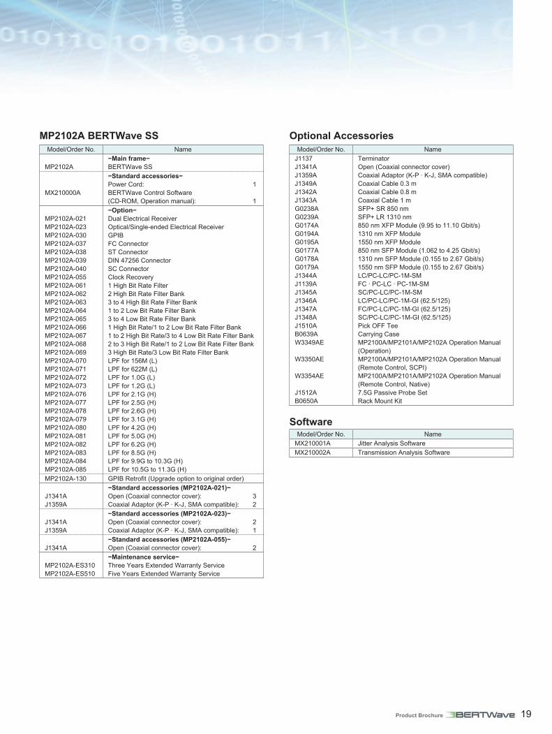
MP2102A BERTWave SSModel/Order No. Name
MP2102A−Main frame−BERTWave SS
MX210000A
−Standard accessories−Power Cord: 1BERTWave Control Software (CD-ROM, Operation manual): 1
MP2102A-021MP2102A-023MP2102A-030MP2102A-037MP2102A-038MP2102A-039MP2102A-040MP2102A-055MP2102A-061MP2102A-062MP2102A-063MP2102A-064MP2102A-065MP2102A-066MP2102A-067MP2102A-068MP2102A-069MP2102A-070MP2102A-071MP2102A-072MP2102A-073MP2102A-076MP2102A-077MP2102A-078MP2102A-079MP2102A-080MP2102A-081MP2102A-082MP2102A-083MP2102A-084MP2102A-085
−Option−Dual Electrical ReceiverOptical/Single-ended Electrical ReceiverGPIBFC ConnectorST ConnectorDIN 47256 ConnectorSC ConnectorClock Recovery1 High Bit Rate Filter2 High Bit Rate Filter Bank3 to 4 High Bit Rate Filter Bank1 to 2 Low Bit Rate Filter Bank3 to 4 Low Bit Rate Filter Bank1 High Bit Rate/1 to 2 Low Bit Rate Filter Bank 1 to 2 High Bit Rate/3 to 4 Low Bit Rate Filter Bank2 to 3 High Bit Rate/1 to 2 Low Bit Rate Filter Bank3 High Bit Rate/3 Low Bit Rate Filter BankLPF for 156M (L)LPF for 622M (L)LPF for 1.0G (L)LPF for 1.2G (L)LPF for 2.1G (H)LPF for 2.5G (H)LPF for 2.6G (H)LPF for 3.1G (H)LPF for 4.2G (H)LPF for 5.0G (H)LPF for 6.2G (H)LPF for 8.5G (H)LPF for 9.9G to 10.3G (H)LPF for 10.5G to 11.3G (H)
MP2102A-130 GPIB Retrofit (Upgrade option to original order)
J1341AJ1359A
−Standard accessories (MP2102A-021)−Open (Coaxial connector cover): 3Coaxial Adaptor (K-P · K-J, SMA compatible): 2
J1341AJ1359A
−Standard accessories (MP2102A-023)−Open (Coaxial connector cover): 2Coaxial Adaptor (K-P · K-J, SMA compatible): 1
J1341A−Standard accessories (MP2102A-055)−Open (Coaxial connector cover): 2
MP2102A-ES310MP2102A-ES510
−Maintenance service−Three Years Extended Warranty ServiceFive Years Extended Warranty Service
Optional AccessoriesModel/Order No. Name
J1137J1341AJ1359AJ1349AJ1342AJ1343AG0238AG0239AG0174AG0194AG0195AG0177AG0178AG0179AJ1344AJ1139AJ1345AJ1346AJ1347AJ1348AJ1510AB0639AW3349AE
W3350AE
W3354AE
J1512AB0650A
TerminatorOpen (Coaxial connector cover)Coaxial Adaptor (K-P · K-J, SMA compatible)Coaxial Cable 0.3 mCoaxial Cable 0.8 mCoaxial Cable 1 mSFP+ SR 850 nmSFP+ LR 1310 nm850 nm XFP Module (9.95 to 11.10 Gbit/s)1310 nm XFP Module 1550 nm XFP Module850 nm SFP Module (1.062 to 4.25 Gbit/s)1310 nm SFP Module (0.155 to 2.67 Gbit/s)1550 nm SFP Module (0.155 to 2.67 Gbit/s)LC/PC-LC/PC-1M-SMFC · PC-LC · PC-1M-SMSC/PC-LC/PC-1M-SMLC/PC-LC/PC-1M-GI (62.5/125)FC/PC-LC/PC-1M-GI (62.5/125)SC/PC-LC/PC-1M-GI (62.5/125)Pick OFF TeeCarrying CaseMP2100A/MP2101A/MP2102A Operation Manual (Operation)MP2100A/MP2101A/MP2102A Operation Manual (Remote Control, SCPI)MP2100A/MP2101A/MP2102A Operation Manual (Remote Control, Native)7.5G Passive Probe SetRack Mount Kit
SoftwareModel/Order No. Name
MX210001A Jitter Analysis SoftwareMX210002A Transmission Analysis Software

Anritsu Corporation 5-1-1 Onna, Atsugi-shi, Kanagawa, 243-8555 JapanPhone: +81-46-223-1111Fax: +81-46-296-1238
• U.S.A.Anritsu Company1155 East Collins Blvd., Suite 100, Richardson, TX 75081, U.S.A.Toll Free: 1-800-267-4878Phone: +1-972-644-1777Fax: +1-972-671-1877
• CanadaAnritsu Electronics Ltd.700 Silver Seven Road, Suite 120, Kanata, Ontario K2V 1C3, CanadaPhone: +1-613-591-2003 Fax: +1-613-591-1006
• Brazil Anritsu Eletrônica Ltda.Praça Amadeu Amaral, 27 - 1 Andar01327-010 - Bela Vista - São Paulo - SP - BrazilPhone: +55-11-3283-2511Fax: +55-11-3288-6940
• MexicoAnritsu Company, S.A. de C.V.Av. Ejército Nacional No. 579 Piso 9, Col. Granada11520 México, D.F., MéxicoPhone: +52-55-1101-2370Fax: +52-55-5254-3147
• U.K.Anritsu EMEA Ltd.200 Capability Green, Luton, Bedfordshire, LU1 3LU, U.K.Phone: +44-1582-433200 Fax: +44-1582-731303
• FranceAnritsu S.A.12 avenue du Québec, Bâtiment Iris 1- Silic 612,91140 VILLEBON SUR YVETTE, FrancePhone: +33-1-60-92-15-50Fax: +33-1-64-46-10-65
• GermanyAnritsu GmbHNemetschek Haus, Konrad-Zuse-Platz 1 81829 München, Germany Phone: +49-89-442308-0 Fax: +49-89-442308-55
• ItalyAnritsu S.r.l.Via Elio Vittorini 129, 00144 Roma, ItalyPhone: +39-6-509-9711 Fax: +39-6-502-2425
• SwedenAnritsu ABBorgarfjordsgatan 13A, 164 40 KISTA, SwedenPhone: +46-8-534-707-00 Fax: +46-8-534-707-30
• FinlandAnritsu ABTeknobulevardi 3-5, FI-01530 VANTAA, FinlandPhone: +358-20-741-8100Fax: +358-20-741-8111
• DenmarkAnritsu A/S (Service Assurance)Anritsu AB (Test & Measurement)Kay Fiskers Plads 9, 2300 Copenhagen S, DenmarkPhone: +45-7211-2200Fax: +45-7211-2210
• RussiaAnritsu EMEA Ltd. Representation Office in RussiaTverskaya str. 16/2, bld. 1, 7th floor.Russia, 125009, MoscowPhone: +7-495-363-1694Fax: +7-495-935-8962
• United Arab EmiratesAnritsu EMEA Ltd.Dubai Liaison OfficeP O Box 500413 - Dubai Internet CityAl Thuraya Building, Tower 1, Suit 701, 7th FloorDubai, United Arab EmiratesPhone: +971-4-3670352Fax: +971-4-3688460
• SingaporeAnritsu Pte. Ltd.60 Alexandra Terrace, #02-08, The Comtech (Lobby A)Singapore 118502Phone: +65-6282-2400Fax: +65-6282-2533
• IndiaAnritsu Pte. Ltd. India Branch Office3rd Floor, Shri Lakshminarayan Niwas, #2726, 80 ft Road, HAL 3rd Stage, Bangalore - 560 075, IndiaPhone: +91-80-4058-1300Fax: +91-80-4058-1301
• P.R. China (Hong Kong)Anritsu Company Ltd.Units 4 & 5, 28th Floor, Greenfield Tower, Concordia Plaza, No. 1 Science Museum Road, Tsim Sha Tsui East, Kowloon, Hong KongPhone: +852-2301-4980Fax: +852-2301-3545
• P.R. China (Beijing)Anritsu Company Ltd.Beijing Representative OfficeRoom 2008, Beijing Fortune Building, No. 5, Dong-San-Huan Bei Road, Chao-Yang District, Beijing 100004, P.R. ChinaPhone: +86-10-6590-9230Fax: +86-10-6590-9235
• KoreaAnritsu Corporation, Ltd.502, 5FL H-Square N B/D, 681Sampyeong-dong, Bundang-gu, Seongnam-si, Gyeonggi-do, 463-400 KoreaPhone: +82-31-696-7750Fax: +82-31-696-7751
• AustraliaAnritsu Pty. Ltd.Unit 21/270 Ferntree Gully Road, Notting Hill, Victoria 3168, AustraliaPhone: +61-3-9558-8177Fax: +61-3-9558-8255
• TaiwanAnritsu Company Inc.7F, No. 316, Sec. 1, NeiHu Rd., Taipei 114, TaiwanPhone: +886-2-8751-1816Fax: +886-2-8751-1817
Specifications are subject to change without notice.
1109
Printed on Recycled Paper
Please Contact:
Catalog No. MP2100Aseries-E-A-1-(6.00) Printed in Japan 26/SEP/2011 ddcw/CDT