Embed Size (px)
Citation preview
1
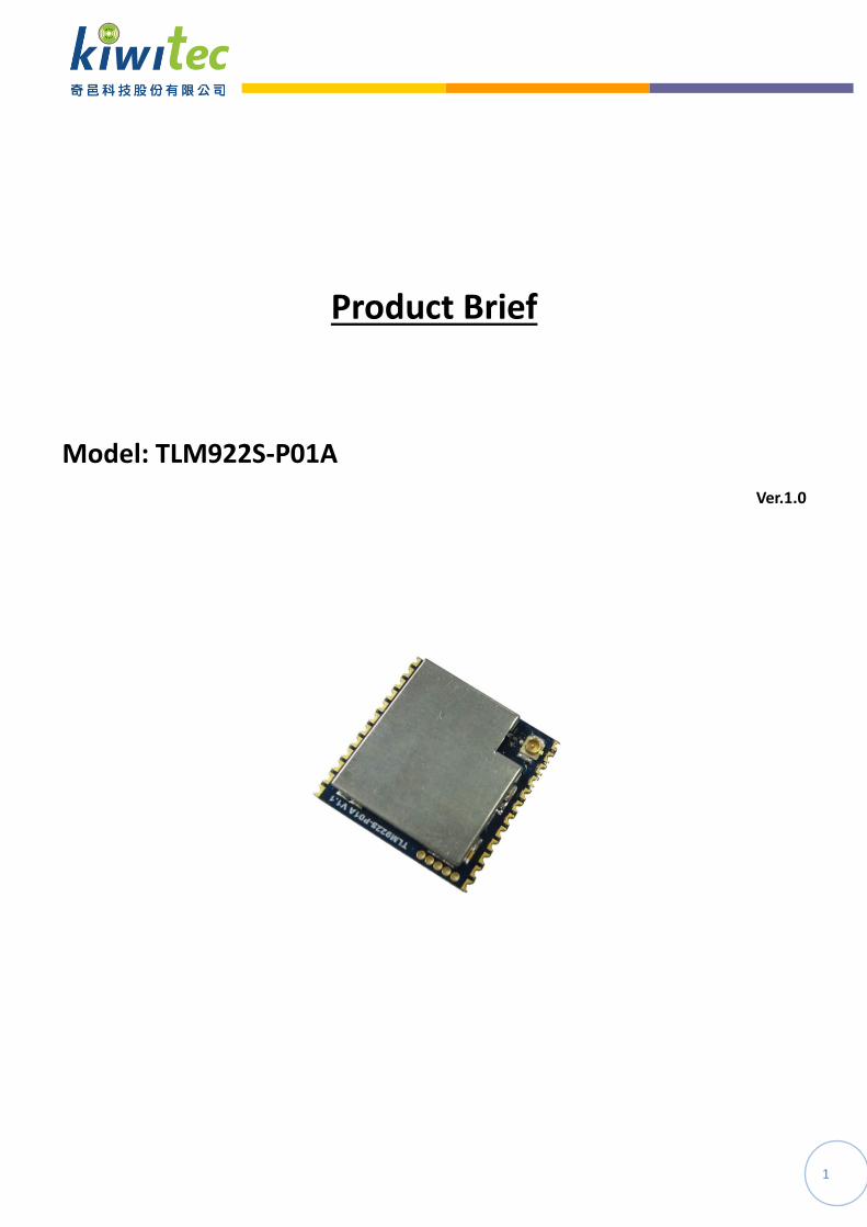
Product Brief
Model: TLM922S-P01A
Ver.1.0

2
Index
1. Overview ..................................................................................................... 3
2. Product Features ......................................................................................... 3
3. Application .................................................................................................. 4
4. Product Specifications ................................................................................. 4
5. PIN Definition .............................................................................................. 6
6. PCB Dimension ............................................................................................ 7
7. Pin Configuration ......................................................................................... 7
8. Distance Measurement in City .................................................................... 9
3
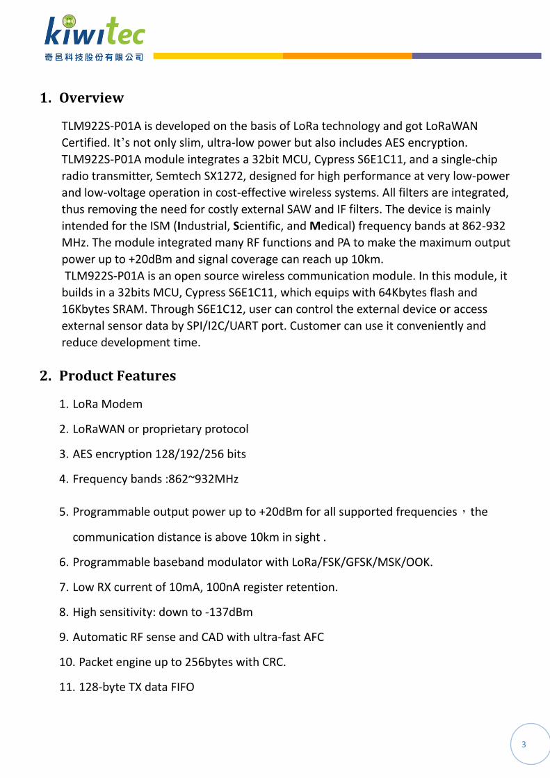
1. Overview
TLM922S-P01A is developed on the basis of LoRa technology and got LoRaWAN
Certified. It’s not only slim, ultra-low power but also includes AES encryption.
TLM922S-P01A module integrates a 32bit MCU, Cypress S6E1C11, and a single-chip
radio transmitter, Semtech SX1272, designed for high performance at very low-power
and low-voltage operation in cost-effective wireless systems. All filters are integrated,
thus removing the need for costly external SAW and IF filters. The device is mainly
intended for the ISM (Industrial, Scientific, and Medical) frequency bands at 862-932
MHz. The module integrated many RF functions and PA to make the maximum output
power up to +20dBm and signal coverage can reach up 10km.
TLM922S-P01A is an open source wireless communication module. In this module, it
builds in a 32bits MCU, Cypress S6E1C11, which equips with 64Kbytes flash and
16Kbytes SRAM. Through S6E1C12, user can control the external device or access
external sensor data by SPI/I2C/UART port. Customer can use it conveniently and
reduce development time.
2. Product Features
1. LoRa Modem
2. LoRaWAN or proprietary protocol
3. AES encryption 128/192/256 bits
4. Frequency bands :862~932MHz
5. Programmable output power up to +20dBm for all supported frequencies,the
communication distance is above 10km in sight .
6. Programmable baseband modulator with LoRa/FSK/GFSK/MSK/OOK.
7. Low RX current of 10mA, 100nA register retention.
8. High sensitivity: down to -137dBm
9. Automatic RF sense and CAD with ultra-fast AFC
10. Packet engine up to 256bytes with CRC.
11. 128-byte TX data FIFO

4
12. Transmit mode at +20dBm output power <140mA
13. Low current consumption at power down state <3uA
14. Small dimension: 23.5mm×23.2mm×3.1 mm
15. Certification: LoRaWAN, TELEC, VCCI
3. Application
1. Automation and safety alarm in the community.
2. Various automated smart meters, such as water meter, gas meter and electricity meter.
3. Long range communication data collection and integration.
4. Outdoor information monitoring and collection, such as temperature, humidity and air quality information.
5. Electricity facilities measurement and management, such as smart street lighting.
6. Agriculture and animal husbandry monitoring and management.
4. Product Specifications
Transceiver SX1272
MCU Cypress S6E1C11
Operating supply voltage DC 2.2~3.6V
Frequency 862~932MHz
Frequency accuracy ±10KHz
Modulation LoRa/GFSK/FSK/OOK/MSK
Transmit power -2~+20dBm
TX current consumption <140mA
Sleep State current consumption <3uA

5
Data rate 0.244~18.2Kbps(LoRa) / 300Kbps(FSK)
Spurious emissions and harmonics < -30dBm
Communication distance 10Km
Antenna impedance 50ohm
Operating temperature -40~+85 °C
Storage temperature range -50~+125°C
Dimension 23.5mm×23.2mm×3.1 mm
Certificate of Compliance LoRaWAN, VCCI, TELEC
Note:
The module transmission data rate will affect Transmission distance, the higher the data rate , the closer the distance, and the lower the receiving sensitivity.
The supply voltage to the module will affect TX power, in the operating supply voltage range, the lower the voltage to get the lower the TX power.
The antenna will strongly affect the communication distance, please select matched antenna and connect it correctly.
The module mount will affect the communication distance.

6
5. PIN Definition

7
6. PCB Dimension
7. Pin Configuration
PIN 1. PIN NAME 2. Description
1 3. MD0 4. During normal operation, input MD0="L".
5. During serial programming to Flash memory, input
MD0="H".
2 6. GPIO_ADC0 7. A/D converter analog input pin and
general-purpose I/O
3 8. SPI_MISO 9. SPI interface
4 10. SPI_MOSI 11. SPI interface
5 12. SPI_SCK 13. SPI interface

8
6 14. SPI_CS 15. SPI interface
7 16. I2C_SDA 17. I2C interface
8 18. I2C_SCL 19. I2C interface
9 20. GPIO_ADC1 21. A/D converter analog input pin and
general-purpose I/O
10 22. GND 23. RF ground
11 24. ANT 25. RF output signal
12 26. GND 27. RF ground
13 28. GND 29. System ground
14 30. GND 31. System ground
15 32. +3.3V 33. Power source
16 34. +3.3V 35. Power source
17 36. GPIO_INT2 37. External interrupt request and general-purpose I/O
18 38. SWCLK 39. Serial wire debug interface clock input pin
19 40. SWDIO 41. Serial wire debug interface data input output pin
20 42. GPIO_INT3 43. External interrupt request and general-purpose I/O
21 44. UART_RX 45. UART interface
22 46. UART_TX 47. UART interface
23 48. GPIO_INT0 49. External interrupt request and general-purpose I/O
24 50. RST_M0 51. External Reset Input pin.
Note:
The module power supply voltage range is DC 3.0~3.6V, above DC 3.6V, the module will damage. It is recommended work at DC 3.3 V.
The module interface use half circle pad to soldering on the system PCB board, the GND must soldering to the system digital GND reliably, or use connector to connect main-board .
The antenna must the get to the module’s ANT pin as close as possible.
The module’s pin GPIO_ADC and GPIO_INT are general digital I/O ports, they also can be programmable to A/D converter analog input pin and external interrupt pin.

9
8. Distance Measurement in City