Embed Size (px)
Citation preview
Copyright 2008 Carrier Corporation Form 45-3PD
The 45J,M,K,N,Q,R units were de-signed to maintain accurate tempera-tures in the conditioned zone. They offer:• Series units that provide constant
airflow to the zone to help maintain optimal occupant comfort
• Parallel units that draw primary air from the air source and warm air from the return plenum to satisfy zone temperature requirements
• 45K,N quiet fan units were designed with the lowest sound levels in the industry
• 45Q,R low profile units offer a low height (10 5/8 in.) for installation in compact spaces
Features/BenefitsCarrier’s 45J,M,K,N,Q,R fan-powered variable air volume (VAV) units are designed to maintain optimum temperatures in the conditioned zone through the accurate mixing of plenum return air and cold primary air to the zone.Flexible, high performance units
The 45 Series units are available in 6 sizes, with capacities ranging from 90 to 3700 cfm. All units have round inlets (6 in. to 16 in. diameter, depend-ing on model size and type) to fit stan-dard spiral and flex duct. Fan airflow is field-adjustable through the use of an electronic fan speed controller (SCR). The 45 Series units offer excellent per-formance characteristics and afford-ability in a compact unit with optimum physical dimensions.
45J,M,K,N,Q,RStandard, Quiet, and
Low Profile Fan PoweredVariable Air Volume Terminals
90 to 3900 CfmSeries Fan Box — 45J,K,Q
Parallel Fan Box — 45M,N,R
ProductData
45J,M
45K,N
45Q,R

2
The 45J,K,Q constant volume oper-ation unit’s recirculation fan draws cold air from the primary air duct and warm air from the return plenum in varying amounts to satisfy zone temperature requirements. Warm air and cold air blend in the unit fan before entering the discharge plenum. Optional heat-ing coils may be used for additional ter-minal heating requirements.
The 45M,N,R units feature intermit-tent parallel fan operation. It is de-signed to maintain optimum occupant comfort levels by supplying warm in-duced plenum air, cold primary air (VAV), or a mixture of both to condi-tion the space. The 45M,N,R fan cy-cles on to satisfy zone heating require-ments. Optional heating coils provide terminal heat only after the fan has cy-cled on.The 45K,N fan-powered variable air volume (VAV) units have a premium design with the lowest sound levels in the industry, as well as a multitude of linings to meet all IAQ (indoor air qual-ity) designs. The units are designed to allow maximum flexibility in configura-tion and control. Strong integral pan-el/post construction allows long lasting service access. Multi-voltage motors are standard. The series fan arrange-ment in the 45K unit has the lowest possible sound levels available, while providing a constant airflow to the space.
The 45Q,R units offer excellent performance characteristics and affordability in a compact unit with optimum low height physical dimen-sions (105/8 in. high).The standard unit casing is constructed of 22-gage zinc coated steel (20 gage optional) with 1/2 in. dual density fiber-glass insulation and a removable bot-tom panel for easy access. Recircula-tion fans, mounted on permanently lu-bricated, multi-voltage motors, combined with dual density insulation and foil lined option, ensure quiet and clean operation. An external filter op-tion offers quick access for routine maintenance.
All casings and liners meet UL-181 (Underwriters’ Laboratories) and NFPA-90A (National Fire Protection Association). Recirculation fan motors are certified in accordance with ARI (Air Conditioning and Refrigeration In-stitute) Standard 880.
Superior control offeringsEach 45 Series unit is supplied with a linear averaging flow probe as a stan-dard feature. This probe offers a flow averaging capability and results in flow sensing capability equal to any compet-itive unit. All units have a standard SCR.
Factory-installed control options in-clude pressure- independent pneumatic, analog electronic, and Carrier variable volume and temperature (VVT®) and
Product Integrated Controls (PIC). Both VVT and PIC controls are communicat-ing controls; the PIC units provide a control option compatible with theCarrier Comfort Network® (CCN)controls.
Pneumatic controls are available with linear actuators and either single-function or multi-function controller. The multi-function controller provides a simple switchover from normally open to normally closed applications.
Electronic control units feature afactory-installed enclosure that pro-vides easy access for field connections.
Designed for easy installationUnits have round inlets with a flange type discharge duct connection.
The units can be specified withelectric or hot water heat, and a num-ber of linings. Each unit features anintegral inlet attenuator for decreasing radiated sound.
Features/Benefits (cont)
Table of contentsPage
Features/Benefits. . . . . . . . . . . . . . . . . . . . . . . . . . . . . . . . . . . . . . . . . . . 1,2Options and Accessories. . . . . . . . . . . . . . . . . . . . . . . . . . . . . . . . . . . . . 3-11Selection Procedure . . . . . . . . . . . . . . . . . . . . . . . . . . . . . . . . . . . . . . . . . 11Application Data . . . . . . . . . . . . . . . . . . . . . . . . . . . . . . . . . . . . . . . . . . . 1245J,M Model Number Nomenclature . . . . . . . . . . . . . . . . . . . . . . . . . . . . . . . 13 Physical Data . . . . . . . . . . . . . . . . . . . . . . . . . . . . . . . . . . . . . . . . . 14-16 Dimensions . . . . . . . . . . . . . . . . . . . . . . . . . . . . . . . . . . . . . . . . . . 17-27
Performance Data . . . . . . . . . . . . . . . . . . . . . . . . . . . . . . . . . . . . . 28-39Electrical Data . . . . . . . . . . . . . . . . . . . . . . . . . . . . . . . . . . . . . . . . . . 40
45K,N Model Number Nomenclature . . . . . . . . . . . . . . . . . . . . . . . . . . . . . . . 41 Physical Data . . . . . . . . . . . . . . . . . . . . . . . . . . . . . . . . . . . . . . . . . 42,43 Dimensions . . . . . . . . . . . . . . . . . . . . . . . . . . . . . . . . . . . . . . . . . . 44-52 Performance Data . . . . . . . . . . . . . . . . . . . . . . . . . . . . . . . . . . . . . 53-73 Electrical Data . . . . . . . . . . . . . . . . . . . . . . . . . . . . . . . . . . . . . . . . . . 7445Q,R Model Number Nomenclature . . . . . . . . . . . . . . . . . . . . . . . . . . . . . . . 75 Physical Data . . . . . . . . . . . . . . . . . . . . . . . . . . . . . . . . . . . . . . . . . 76,77 Dimensions . . . . . . . . . . . . . . . . . . . . . . . . . . . . . . . . . . . . . . . . . . 78-85 Performance Data . . . . . . . . . . . . . . . . . . . . . . . . . . . . . . . . . . . . . 86-91 Electrical Data . . . . . . . . . . . . . . . . . . . . . . . . . . . . . . . . . . . . . . . . . . 92Guide Specifications. . . . . . . . . . . . . . . . . . . . . . . . . . . . . . . . . . . . . . 93-102

3
45J and 45M factory-installed options• 20 gage zinc-coated steel construction• 1-in. dual density fiberglass insulation liner• foil encapsulated fiberglass liner• cellular (fiber free) insulation liner• 120, 208/240, or 277 volt ECM (electronically com-
mutated motor) with controls• fused/non-fused door interlocking disconnect switch• induction inlet attenuator and induction air inlet filter• 80/20 nickel-chromium heating element• manual reset cutout• dust-tight control enclosure• hanger brackets• water coil vent and drain• fuse block• Chicago code constructionElectric heatElectric heat options are UL Listed, and meet NEC(National Electrical Code) requirements. Automatic resetthermal cutout and positive pressure airflow switch arestandard. Pneumatic electric switches are standard stepcontrollers when pneumatic control systems are specified.Magnetic contactors are standard step controllers whenelectronic control systems are specified. Control enclosurehouses all control components.Available heater voltages:• 120 v/single phase • 208/240,277 v/single phase• 208/240 v/3 phase/3-wire• 480 v/3 phase/4-wireElectric heat options:• mercury contactors• fuse block with fuses for primary overload protection• disconnect switches• fused disconnect switches• manual reset thermal cutout• dust-tight construction
Electric heaters are slip-in type, integrally mounted tothe terminal unit. Where possible, select heater so thatpower (kW) is a whole number (see Electrical Data section).Rounding to the nearest whole number has negligible im-pact on discharge temperature and power consumption.Hot water coilsHot water coils are enclosed in a galvanized steel casingand constructed of corrugated aluminum fins. The coiltubing is water leak tested to 400 psig. Vent and drainoptions are available.Features include:• 1/2 in. O.D. 0.016-in. thick copper coil tubing• aluminum corrugated fins. 10 per inch• coil casing — 20 gage galvanized steel• slip and drive cleat discharge duct connection• optional access panelControl optionsThe 45J and 45M units are offered with a wide variety offactory-mounted controls that regulate the volume of airdelivery from the unit and respond to cooling and heatingload requirements of the conditioned space. Stand-alonecontrols will fulfill the thermal requirements of a given con-trol space. These devices are available in both pneumatic
and electronic arrangements. Carrier VVT® electroniccontrols and PIC DDC (direct digital controls) are commu-nicating controls which are integrated with the building sys-tem. The PIC controls are compatible with CCN system.Many DDC control packages by others are available forconsignment mounting, as indicated.
Control offerings are: A: Analog Electronic C: PIC DDC ComfortID™ Electronic Controls (compatible with CCN) P: Pneumatic V: 3V™, VVT Electronic (45M only) N: No Controls or DDC by others
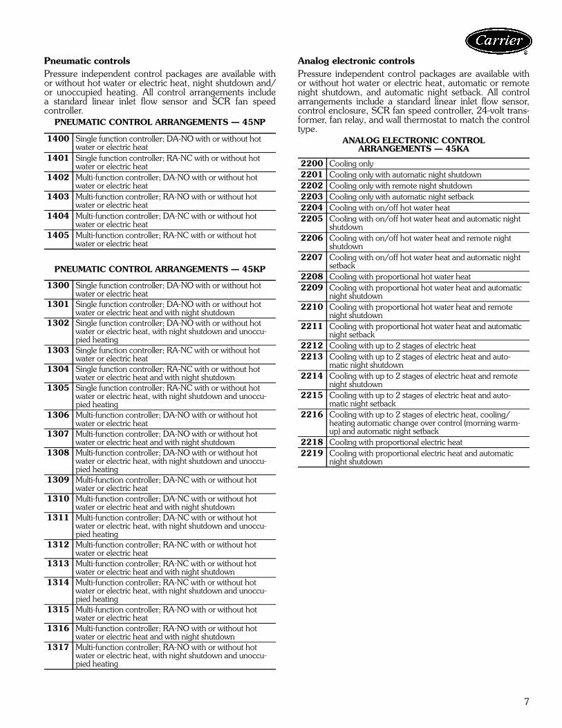
Each control approach offers a variety of operating func-tions; a control package number identifies combinations ofcontrol functions. Because of the variety of functions avail-able, circuit diagrams, operating sequences, and functiondescriptions are contained in separate Application Datapublications. Refer to the specific publication for details.Analog electronic controlsPressure independent control packages are available withor without hot water or electric heat, automatic or remotenight shutdown, and automatic night setback. All controlarrangements include a standard linear inlet flow sensor,control enclosure, SCR fan speed controller, transformerto 24 volts, fan relay, and wall thermostat to match thecontrol type.
ANALOG ELECTRONIC CONTROL ARRANGEMENTS — 45JA
2200 Cooling only2201 Cooling only with automatic night shutdown2202 Cooling only with remote night shutdown2203 Cooling only with automatic night setback2204 Cooling with on/off hot water heat2205 Cooling with on/off hot water heat and automatic
night shutdown2206 Cooling with on/off hot water heat and remote
night shutdown2207 Cooling with on/off hot water heat and automatic
night setback2208 Cooling with proportional hot water heat2209 Cooling with proportional hot water heat and
automatic night shutdown2210 Cooling with proportional hot water heat and
remote night shutdown2211 Cooling with proportional hot water heat and
automatic night setback2212 Cooling with up to 2 stages of electric heat2213 Cooling with up to 2 stages of electric heat and
automatic night shutdown2214 Cooling with up to 2 stages of electric heat and
remote night shutdown2215 Cooling with up to 2 stages of electric heat and
automatic night setback2216 Cooling with up to 2 stages of electric heat,
cooling/heating automatic change over control (morning warm-up) and automatic night setback
2218 Cooling with proportional electric heat
Options and accessories — 45J and 45M
4
ANALOG ELECTRONIC CONTROLARRANGEMENTS — 45MA
NOTE: The 45M control type 2313 is for SSR (solid-staterelay) heat only.Pneumatic controls Pressure independent control packages are available withor without hot water or electric heat, night shutdown and/or unoccupied heating. All control arrangements include astandard linear inlet flow sensor and SCR fan speed con-troller.
The single function controller provides single functions,i.e., DA-NO. Multi/4-function controllers are capable ofproviding DA-NO, DA-NC, RA-NC or RA-NO functions.
PNEUMATIC CONTROL ARRANGEMENTS — 45JP
PNEUMATIC CONTROL ARRANGEMENTS — 45MP
2300 Cooling with sequenced fan2301 Cooling with sequenced fan and auto. night
shutdown2302 Cooling with sequenced fan and auto. night
setback2303 Cooling with sequenced fan and on/off hot water
heat2304 Cooling with sequenced fan and on/off hot water
heat and automatic night shutdown2305 Cooling with sequenced fan and on/off hot water
heat and automatic night setback2306 Cooling with sequenced fan and proportional hot
water heat2307 Cooling with sequenced fan proportional hot
water heat and automatic night shutdown2308 Cooling with sequenced fan proportional hot
water heat and automatic night setback2309 Cooling with sequenced fan and up to 2-stages
of electrical heat2310 Cooling with sequenced fan up to 2-stages of
electric heat and automatic night shutdown2311 Cooling with sequenced fan up to 2-stages of
electric heat and automatic night setback2313 Cooling with sequenced fan and proportional
electric heat
DA — Direct acting thermostatRA — Reverse acting thermostatNO — Normally open damper positionNC — Normally closed damper position
1300 Single function controller; DA-NO with or without hot water or electric heat
1301 Single function controller; DA-NO with or without hot water or electric heat and with night shutdown
1302 Single function controller; DA-NO with or without hot water or electric heat, with night shutdown and unoccupied heating
1303 Single function controller; RA-NC with or without hot water or electric heat
1304 Single function controller; RA-NC with or without hot water or electric heat and with night shutdown
1305 Single function controller; RA-NC with or without hot water or electric heat, with night shutdown and unoccupied heating
1306 Multi-function controller; DA-NO with or without hot water or electric heat
1307 Multi-function controller; DA-NO with or without hot water or electric heat and with night shutdown
1308 Multi-function controller; DA-NO with or without hot water or electric heat, with night shutdown and unoccupied heating
1309 Multi-function controller; DA-NC with or without hot water or electric heat
1310 Multi-function controller; DA-NC with or without hot water or electric heat and with night shutdown
1311 Multi-function controller; DA-NC with or without hot water or electric heat, with night shutdown and unoccupied heating
1312 Multi-function controller; RA-NC with or without hot water or electric heat
1313 Multi-function controller; RA-NC with or without hot water or electric heat and with night shutdown
1314 Multi-function controller; RA-NC with or without hot water or electric heat, with night shutdown and unoccupied heating
1315 Multi-function controller; RA-NO with or without hot water or electric heat
1316 Multi-function controller; RA-NO with or without hot water or electric heat and with night shutdown
1317 Multi-function controller; RA-NO with or without hot water or electric heat, with night shutdown and unoccupied heating
1400 1 function DA-NO with or without optional heat1401 1 function RA-NC with or without optional heat1402 4 function DA-NO with or without optional heat1403 4 function RA-NO with or without optional heat1404 4 function DA-NC with or without optional heat 1405 4 function RA-NC with or without optional heat
Options and accessories — 45J and 45M (cont)
5
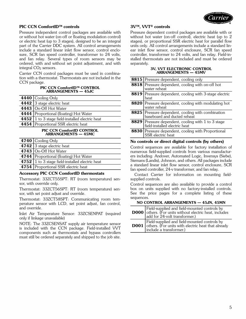
PIC CCN ComfortID™ controlsPressure independent control packages are available withor without hot water (on-off or floating modulation control)or electric heat (up to 3 stages), designed to be an integralpart of the Carrier DDC system. All control arrangementsinclude a standard linear inlet flow sensor, control enclo-sure, SCR fan speed controller, transformer to 24 volts,and fan relay. Several types of room sensors may beordered, with and without set point adjustment, and withintegral CO2 sensors.Carrier CCN control packages must be used in combina-tion with a thermostat. Thermostats are not included in theCCN package.
PIC CCN ComfortID™ CONTROLARRANGEMENTS — 45JC
PIC CCN ComfortID CONTROLARRANGEMENTS — 45MC
Accessory PIC CCN ComfortID thermostatsThermostat: 33ZCT55SPT: RT (room temperature) sen-sor, with override only.Thermostat: 33ZCT56SPT: RT (room temperature) sen-sor, with set point adjust and override.Thermostat: 33ZCT58SPT: Communicating room tem-perature sensor with LCD, set point adjust, fan control,and override.Inlet Air Temperature Sensor: 33ZCSENPAT (requiredonly if linkage unavailable)NOTE: The 33ZCSENSAT supply air temperature sensoris included with the CCN package. Field-installed VVTcomponents such as thermostats and bypass controllersmust still be ordered separately and shipped to the job site.
3V™, VVT® controlsPressure dependent control packages are available with orwithout hot water (on-off control), electric heat (up to 2stages), or proportional SSR electric heat for parallel flowunits only. All control arrangements include a standard lin-ear inlet flow sensor, control enclosure, SCR fan speedcontroller, transformer to 24 volts, and fan relay. Field-in-stalled thermostats are not included and must be orderedseparately.
3V, VVT ELECTRONIC CONTROLARRANGEMENTS — 45MV
No controls or direct digital controls (by others)Control sequences are available for factory installation ofnumerous field-supplied controls from various manufactur-ers including: Andover, Automated Logic, Invensys (Siebe),Siemans (Landis), Johnson, and others. All packages includea standard linear inlet flow sensor, control enclosure, SCRfan speed controller, 24-v transformer, and fan relay.
Contact Carrier for information on mounting field-supplied controls.Control sequences are also available to provide a controlbox on units supplied with no factory-installed controls.See the price pages for a complete listing of thesesequences.
NO CONTROL ARRANGEMENTS — 45JN, 45MN
4440 Cooling Only4442 3 stage electric heat4443 On-Off Hot Water4444 Proportional (floating) Hot Water4452 1 to 3 stage field-installed electric heat4454 Proportional SSR electric heat
4740 Cooling Only4742 3 stage electric heat4743 On-Off Hot Water4744 Proportional (floating) Hot Water4752 1 to 3 stage field-installed electric heat4754 Proportional SSR electric heat
8815 Pressure dependent, cooling only8818 Pressure dependent, cooling with on-off hot
water reheat8819 Pressure dependent, cooling with 3-stage electric
heat8820 Pressure dependent, cooling with modulating hot
water reheat8825 Pressure dependent, cooling with combination
baseboard and ducted reheat8829 Pressure dependent, cooling with 1 to 3 stage
field-installed electric heat8830 Pressure dependent, cooling with Proportional
SSR electric heat
D000Field-supplied and field-mounted controls by others. (For units without electric heat, includes add for 24-volt transformer.)
D001Field-supplied and field-mounted controls by others. (For units with electric heat that already include a transformer.)

6
45K and 45N factory-installed options• hot water heat (inlet or discharge, 45N)• electric heat • liners:
- 1-in. dual density fiberglass insulation- foil encapsulated fiberglass- cellular insulation- Steriliner- Sterilwall- no liner- perforated wall
• recirculated air filter• motor disconnect• motor fusing• dust-tight control enclosure• hanger brackets (not available with sterilwall liner
option)• fan motors, 277-v single phase ECM (electronically
commutated motor)Electric heatElectric heat options are UL listed, and meet NEC(National Electrical Code) requirements. Automatic resetthermal cutout and positive pressure airflow switch arestandard. Pneumatic electric switches are standard stepcontrollers when pneumatic control systems are specified.Magnetic contactors are standard step controllers whenelectronic control systems are specified. Control enclosurehouses all control components.Available heater voltages• 120 v/single phase• 208/240, 277 v/single phase• 208/240 v/3-phase/3-wire• 480 v/3-phase/4-wireElectric heat options• mercury contactors• fuse block with fuses for primary overload protection• disconnect switches• fused disconnect switches• manual reset thermal cutout• dust-tight construction
Electric heaters are slip-in type, integrally mounted tothe terminal unit. Where possible, select heater so thatpower (kW) is a whole number (see Electrical Data section).Rounding to the nearest whole number has negligibleimpact on discharge temperature and power consumption.Hot water coilsHot water coils are enclosed in a galvanized steel casingand constructed of corrugated aluminum fins. The coil tub-ing is water leak tested to 400 psig. Vent and drain optionsare available.Features include:• 1/2 in. O.D. 0.016-in. thick copper coil tubing• aluminum corrugated fins. 10 per inch• coil casing — 20 gage galvanized steel• slip and drive cleat discharge duct connection• optional access panelFan motors• Optional 277-volt, single-phase ECM (electronically
commutated motor) fan motors include either a DCU(digitally controlled unit) or ACU (analog controlled unit)speed controller. The DCU fan speed control can bemanually set at the factory and/or is manually field set
and is field adjustable. The ACU control providesa means to remotely set and/or adjust the fanspeed. (Available on 45K sizes 4, 6, and 7 on 45N sizes4 and 7.)
• Motor disconnect switch (not required if the unit isequipped with electric heat, including the door-lockingdisconnect option).
• Motor fusing (not required if unit is equipped with elec-tric heat, including the fusing option).
• 480-v, 3-phase, 3-wire units not available.Control optionsThe 45K,45N fan powered units are offered with a widevariety of factory-mounted controls that regulate the vol-ume of air delivery from the unit and respond to coolingand heating load requirements of the conditioned space.Stand-alone controls will fulfill the thermal requirements ofa given control space. These devices are available in bothpneumatic and electronic arrangements. Carrier VVT®electronic controls and PIC DDC (direct digital controls) arecommunicating controls which are integrated with thebuilding system. The PIC controls are compatible withCCN system. Many DDC control packages by others areavailable for consignment mounting, as indicated.The controls for the 45K are identified as follows: 45KA: Analog Electronic 45KC: PIC DDC ComfortID™ Electronic Controls (compatible with CCN) 45KP: Pneumatic 45KN: No Controls or DDC by othersThe controls for the 45N are identified as follows: 45NA: Analog Electronic 45NC: PIC DDC ComfortID™ Electronic Controls (compatible with CCN) 45NP: Pneumatic 45NV: 3V™, VVT® Electronic 45NN: No Controls or DDC by others
Each control approach offers a variety of operating func-tions; a control package number identifies combinations ofcontrol functions. The following tables list the basic func-tion arrangements for each of the basic control offerings.Because of the variety of functions available, circuit dia-grams, operating sequences, and function descriptions arecontained in separate Application Data publications. Referto the specific control publication for details.The single function controller provides single functions,i.e., DA-NO; multi-function controllers are capable of pro-viding DA-NO, DA-NC, RA-NC or RA-NO functions.DA — Direct acting thermostatNC — Normally closed damper positionNO — Normally open damper positionRA — Reverse acting thermostat
Options and accessories — 45K and 45N
7
Pneumatic controlsPressure independent control packages are available withor without hot water or electric heat, night shutdown and/or unoccupied heating. All control arrangements includea standard linear inlet flow sensor and SCR fan speedcontroller.
PNEUMATIC CONTROL ARRANGEMENTS — 45NP
PNEUMATIC CONTROL ARRANGEMENTS — 45KP
Analog electronic controlsPressure independent control packages are available withor without hot water or electric heat, automatic or remotenight shutdown, and automatic night setback. All controlarrangements include a standard linear inlet flow sensor,control enclosure, SCR fan speed controller, 24-volt trans-former, fan relay, and wall thermostat to match the controltype.
ANALOG ELECTRONIC CONTROLARRANGEMENTS — 45KA
1400 Single function controller; DA-NO with or without hot water or electric heat
1401 Single function controller; RA-NC with or without hot water or electric heat
1402 Multi-function controller; DA-NO with or without hot water or electric heat
1403 Multi-function controller; RA-NO with or without hot water or electric heat
1404 Multi-function controller; DA-NC with or without hot water or electric heat
1405 Multi-function controller; RA-NC with or without hot water or electric heat
1300 Single function controller; DA-NO with or without hot water or electric heat
1301 Single function controller; DA-NO with or without hot water or electric heat and with night shutdown
1302 Single function controller; DA-NO with or without hot water or electric heat, with night shutdown and unoccu-pied heating
1303 Single function controller; RA-NC with or without hot water or electric heat
1304 Single function controller; RA-NC with or without hot water or electric heat and with night shutdown
1305 Single function controller; RA-NC with or without hot water or electric heat, with night shutdown and unoccu-pied heating
1306 Multi-function controller; DA-NO with or without hot water or electric heat
1307 Multi-function controller; DA-NO with or without hot water or electric heat and with night shutdown
1308 Multi-function controller; DA-NO with or without hot water or electric heat, with night shutdown and unoccu-pied heating
1309 Multi-function controller; DA-NC with or without hot water or electric heat
1310 Multi-function controller; DA-NC with or without hot water or electric heat and with night shutdown
1311 Multi-function controller; DA-NC with or without hot water or electric heat, with night shutdown and unoccu-pied heating
1312 Multi-function controller; RA-NC with or without hot water or electric heat
1313 Multi-function controller; RA-NC with or without hot water or electric heat and with night shutdown
1314 Multi-function controller; RA-NC with or without hot water or electric heat, with night shutdown and unoccu-pied heating
1315 Multi-function controller; RA-NO with or without hot water or electric heat
1316 Multi-function controller; RA-NO with or without hot water or electric heat and with night shutdown
1317 Multi-function controller; RA-NO with or without hot water or electric heat, with night shutdown and unoccu-pied heating
2200 Cooling only2201 Cooling only with automatic night shutdown2202 Cooling only with remote night shutdown2203 Cooling only with automatic night setback2204 Cooling with on/off hot water heat2205 Cooling with on/off hot water heat and automatic night
shutdown2206 Cooling with on/off hot water heat and remote night
shutdown2207 Cooling with on/off hot water heat and automatic night
setback2208 Cooling with proportional hot water heat2209 Cooling with proportional hot water heat and automatic
night shutdown2210 Cooling with proportional hot water heat and remote
night shutdown2211 Cooling with proportional hot water heat and automatic
night setback2212 Cooling with up to 2 stages of electric heat2213 Cooling with up to 2 stages of electric heat and auto-
matic night shutdown2214 Cooling with up to 2 stages of electric heat and remote
night shutdown2215 Cooling with up to 2 stages of electric heat and auto-
matic night setback 2216 Cooling with up to 2 stages of electric heat, cooling/
heating automatic change over control (morning warm-up) and automatic night setback
2218 Cooling with proportional electric heat2219 Cooling with proportional electric heat and automatic
night shutdown

8
ANALOG ELECTRONIC CONTROLARRANGEMENTS — 45NA
PIC CCN ComfortID™ controlsPressure independent control packages are available withor without hot water (on-off or floating modulation control)or electric heat (up to 3 stages), designed to be an integralpart of the Carrier DDC system. All control arrangementsinclude a standard linear inlet flow sensor, control enclo-sure, SCR fan speed controller, 24-volt transformer, andfan relay. Several types of room sensors may be ordered,with and without set point adjustment, and with integralCO2 sensors. Carrier CCN control packages must be used in combina-tion with a thermostat. Thermostats are not included in theCCN package.
PIC CCN ComfortID™ CONTROLARRANGEMENTS — 45KC
PIC CCN ComfortID CONTROLARRANGEMENTS — 45NC
Accessory PIC CCN ComfortID thermostatsThermostat: 33ZCT55SPT: RT (room temperature) sen-sor, with override only.Thermostat: 33ZCT56SPT: RT (room temperature) sen-sor, with set point adjust and override.Thermostat: 33ZCT58SPT: Communicating room tem-perature sensor with LCD, set point adjust, fan control,and override.Inlet Air Temperature Sensor: 33ZCSENPAT (requiredonly if linkage unavailable)NOTE: The 33ZCSENSAT supply air temperature sensoris included with the CCN package. Field-installed VVTcomponents such as thermostats and bypass controllermust still be ordered separately and shipped to the job site.3V™, VVT® controlsPressure dependent control packages are available with orwithout hot water (on-off control), electric heat (up to 2stages), or proportional SSR electric heat for parallel flowunits only. All control arrangements include a standard lin-ear inlet flow sensor, control enclosure, SCR fan speedcontroller, transformer to 24 volts, and fan relay. Field-in-stalled thermostats are not included and must be orderedseparately.
3V, VVT ELECTRONIC CONTROLARRANGEMENTS — 45NV
No controls or direct digital electronic control arrangements (by others)Control sequences are available for factory installation offield-supplied controls from various manufacturers includ-ing: Andover, Automated Logic, Invensys (Siebe), Siemens(Landis), Johnson, and others.
All packages include a standard linear inlet flow sensor,control enclosure, SCR fan speed controller, 24-volt trans-former and fan relay.Control sequences are also available to provide a controlbox on units supplied with no factory-installed controls.These arrangements include: standard inlet linear flow sen-sor, control enclosure, SCR fan speed controller, 24-volttransformer and fan relay.
NO CONTROL ARRANGEMENTS — 45KN, 45NN
2300 Cooling with sequenced fan2301 Cooling with sequenced fan and automatic night shutdown2302 Cooling with sequenced fan and automatic night setback2303 Cooling with sequenced fan and on/off hot water heat2304 Cooling with sequenced fan, no/off hot water and auto-
matic night shutdown2305 Cooling with sequenced fan, on/off hot water heat and
automatic night setback2306 Cooling with sequenced fan and proportional hot water
heat2307 Cooling with sequenced fan, proportional hot water heat
and automatic night shutdown2308 Cooling with sequenced fan, proportional hot water heat
and automatic night setback2309 Cooling with sequenced fan and up to 2 stages of electric
heat2310 Cooling with sequenced fan, up to 2 stages of electric heat
and automatic night shutdown2311 Cooling with sequenced fan, up to 2 stages of electric heat
and automatic setback2313 Cooling with sequenced fan and proportional electric heat
4440 Cooling only4442 1-3 Stage electric heat4443 On-off hot water4444 Proportional (floating) hot water4452 1 to 3 stage field-installed electric heat4454 Proportional SSR electric heat
4740 Cooling only4742 1-3 Stage electric heat4743 On-off hot water4744 Proportional (floating) hot water4752 1 to 3 stage field-installed electric heat4754 Proportional SSR electric heat
8818 Pressure dependent, cooling with on-off hot water heat8819 Pressure dependent, cooling with 3-stage electric heat8815 Pressure dependent, cooling only8820 Pressure dependent, cooling with modulating hot water
heat8825 Pressure dependent, cooling with combination base-
board and ducted reheat8829 Pressure dependent, cooling with 1 to 3 stages of field-
supplied electric heat8830 Pressure dependent, cooling with proportional SSR elec-
tric heat
D000 Field-supplied and field-mounted controls by others. (For units without electric heat includes 24-volt transformer.)
D001 Field-supplied and field-mounted controls by others.(For units with electric heat and already includes atransformer.)
Options and accessories — 45K and 45N (cont)

9
45Q and 45R factory-installed options• foil encapsulated fiberglass liner• cellular (fiber free) insulation liner• mercury contactors• fused/non-fused door interlocking disconnect switch• recirculated air filter• motor fusing• manual reset cutout• dust-tight construction (control box and/or electric heat
control box)Electric heatElectric heat options are UL Listed and meet NEC(National Electrical Code) requirements. Automatic resetthermal cutout and positive pressure airflow switch arestandard. Pneumatic Electric (PE) switches are standardstep controllers when pneumatic control systems are spec-ified. Magnetic contactors are standard step controllerswhen electronic control systems are specified. Controlenclosure houses all control components.Available heater voltages• 120, 208/240, 277 v/single phase• 208/240 v/3 phase/3-wire• 480 v/3 phase/4-wire(480 v/3 phase /3-wire heaters may be ordered as special)Electric heat options• mercury contactors• fuse block with fuses for primary overload protection• disconnect switches• fused disconnect switches• manual reset thermal cutout• dust-tight construction
Electric heaters are slip-in type, integrally mounted tothe terminal unit. Where possible, select heater so thatpower (kW) is a whole number. Rounding to the nearestwhole number has negligible impact on discharge tempera-ture and power consumption.Hot water coilsHot water coils are enclosed in a galvanized steel casingand constructed of corrugated aluminum fins. The coil tub-ing is water leak tested to 400 psig. Vent and drain optionsare available.Features include:• 1/2 in. O.D. 0.016-in. thick copper coil tubing• aluminum corrugated fins. 10 per inch• coil casing — 20 gage galvanized steel• slip and drive cleat discharge duct connection• optional access panelControl optionsThe 45Q,45R unit is offered with a wide variety of factory-mounted controls that regulate the volume of air deliveryfrom the unit and respond to cooling and heating loadrequirements of the conditioned space.
Stand-alone controls will fulfill the thermal requirements ofa given control space. These devices are available in bothpneumatic and electronic arrangements. Carrier VVT®electronic controls and PIC DDC (direct digital controls) arecommunicating controls which are integrated with thebuilding system. The PIC controls are compatible withCCN system. Many DDC control packages by others areavailable for consignment mounting, as indicated.
Control offerings are:A: Analog ElectronicC: PIC DDC ComfortID™ Electronic Controls
(compatible with CCN)P: PneumaticV: 3V™, VVT Electronic (45R only)N: No Controls or DDC by others.Each control approach offers a variety of operating func-
tions; a control package number identifies combinations ofcontrol functions. Because of the variety of functions avail-able, circuit diagrams, operating sequences, and functiondescriptions are contained in separate Application Data publi-cations. Refer to the specific control publication for details.Pneumatic controlsPressure independent control packages are available withor without hot water or electric heat, night shutdown and/or unoccupied heating. All control arrangements includea standard linear inlet flow sensor and SCR fan speedcontroller.Single function controller: Provides single function,i.e., DA-NOMulti-function controller: Capable of providing DA-NO,DA-NC, RA-NC or RA-NO functions.
PNEUMATIC CONTROL ARRANGEMENTS — 45RP
DA — Direct acting thermostatNC — Normally closed damper positionNO — Normally open damper positionRA — Reverse acting thermostat
1400 Single function controller; DA-NO with or without hot water or electric heat
1401 Single function controller; RA-NC with or without hot water or electric heat
1402 Multi-function controller; DA-NO with or without hot water or electric heat
1403 Multi-function controller; RA-NO with or without hot water or electric heat
1404 Multi-function controller; DA-NC with or without hot water or electric heat
1405 Multi-function controller; RA-NC with or without hot water or electric heat
Options and accessories — 45Q and 45R

10
PNEUMATIC CONTROL ARRANGEMENTS — 45QP
Analog electronic controlsPressure independent control packages are available withor without hot water or electric heat, automatic or remotenight shutdown, and automatic night setback. All controlarrangements include a standard linear inlet flow sensor,control enclosure, SCR fan speed controller, 24-volt trans-former, fan relay, and wall thermostat to match the controltype.
ANALOG ELECTRONIC CONTROLARRANGEMENTS — 45QA
ANALOG ELECTRONIC CONTROLARRANGEMENTS — 45RA
1300 Single function controller; DA-NO with or without hot water or electric heat
1301 Single function controller; DA-NO with or without hot water or electric heat and with night shutdown
1302 Single function controller; DA-NO with or without hot water or electric heat, with night shutdown and unoccupied heating
1303 Single function controller; RA-NC with or without hot water or electric heat
1304 Single function controller; RA-NC with or without hot water or electric heat and with night shutdown
1305 Single function controller; RA-NC with or without hot water or electric heat, with night shutdown and unoccupied heating
1306 Multi-function controller; DA-NO with or without hot water or electric heat
1307 Multi-function controller; DA-NO with or without hot water or electric heat and with night shutdown
1308 Multi-function controller; DA-NO with or without hot water or electric heat, with night shutdown and unoccupied heating
1309 Multi-function controller; DA-NC with or without hot water or electric heat
1310 Multi-function controller; DA-NC with or without hot water or electric heat and with night shutdown
1311 Multi-function controller; DA-NC with or without hot water or electric heat, with night shutdown and unoccupied heating
1312 Multi-function controller; RA-NC with or without hot water or electric heat
1313 Multi-function controller; RA-NC with or without hot water or electric heat and with night shutdown
1314 Multi-function controller; RA-NC with or without hot water or electric heat, with night shutdown and unoccupied heating
1315 Multi-function controller; RA-NO with or without hot water or electric heat
1316 Multi-function controller; RA-NO with or without hot water or electric heat and with night shutdown
1317 Multi-function controller; RA-NO with or without hot water or electric heat, with night shutdown and unoccupied heating
2200 Cooling only2201 Cooling only with automatic night shutdown2202 Cooling only with remote night shutdown2203 Cooling only with automatic night setback2204 Cooling with on/off hot water heat2205 Cooling with on/off hot water heat and automatic
night shutdown2206 Cooling with on/off hot water heat and remote
night shutdown2207 Cooling with on/off hot water heat and automatic
night setback2208 Cooling with proportional hot water heat2209 Cooling with proportional hot water heat and
automatic night shutdown2210 Cooling with proportional hot water heat and
remote night shutdown2211 Cooling with proportional hot water heat and
automatic night setback2212 Cooling with up to 2 stages of electric heat2213 Cooling with up to 2 stages of electric heat and
automatic night shutdown2214 Cooling with up to 2 stages of electric heat and
remote night shutdown2215 Cooling with up to 2 stages of electric heat and
automatic night setback 2216 Cooling with up to 2 stages of electric heat and
morning warm-up2218 Cooling with proportional electric heat
2300 Cooling with sequenced fan2301 Cooling with sequenced fan and automatic night
shutdown2302 Cooling with sequenced fan and automatic night
setback2303 Cooling with sequenced fan and on/off hot water
heat2304 Cooling with sequenced fan, on/off hot water and
automatic night shutdown2305 Cooling with sequenced fan, on/off hot water
heat and automatic night setback2306 Cooling with sequenced fan and proportional hot
water heat2307 Cooling with sequenced fan, proportional hot
water heat and automatic night shutdown2308 Cooling with sequenced fan, proportional hot
water heat and automatic night setback2309 Cooling with sequenced fan and up to 2 stages of
electric heat2310 Cooling with sequenced fan, up to 2 stages of
electric heat and automatic night shutdown2311 Cooling with sequenced fan, up to 2 stages of
electric heat and automatic setback2313 Cooling with sequenced fan and proportional
electric heat
Options and accessories — 45Q and 45R (cont)

11
PIC CCN ComfortID™ controlsPressure Independent control packages are available withor without hot water (on-off or floating modulation control)or electric heat (up to 3 stages), designed to be an integralpart of the Carrier DDC control system. All controlarrangements include a standard linear inlet flow sensor,control enclosure, SCR fan speed controller, transformerto 24 volts, and fan relay. Several types of room sensorsmay be ordered, with and without set point adjustment,and with integral CO2 sensors. Carrier CCN control packages must be used in combina-tion with a thermostat. Thermostats are not included in theCCN package.
PIC CCN ComfortID CONTROLARRANGEMENTS — 45QC
PIC CCN ComfortID CONTROLARRANGEMENTS — 45RC
Accessory PIC CCN ComfortID thermostatsThermostat: 33ZCT55SPT: RT (room temperature) sen-sor, with override only.Thermostat: 33ZCT56SPT: RT (room temperature) sen-sor, with set point adjust and override.Thermostat: 33ZCT58SPT: Communicating room tem-perature sensor with LCD, set point adjust, fan control,and override.Inlet Air Temperature Sensor: 33ZCSENPAT (requiredonly if linkage unavailable)NOTE: The 33ZCSENSAT supply air temperature sensoris included with the CCN package. Field-installed VVTcomponents such as thermostats and bypass controllermust still be ordered separately and shipped to the job site.
3V™, VVT® controlsPressure dependent control packages are available with orwithout hot water (on-off control), electric heat (up to 2stages), or proportional SSR electric heat for parallel flowunits only. All control arrangements include a standard lin-ear inlet flow sensor, control enclosure, SCR fan speedcontroller, transformer to 24 volts, and fan relay. Field-in-stalled thermostats are not included and must be orderedseparately.
3V, VVT ELECTRONIC CONTROLARRANGEMENTS — 45RV
No controls or direct digital electronic control arrangements (by others)Control sequences are available for factory installation offield-supplied controls from various manufacturers includ-ing: Andover, Automated Logic, Invensys (Siebe), Siemans(Landis), Johnson, and others.
All packages include a standard linear inlet flow sensor,control enclosure, SCR fan speed controller, 24-volt trans-former and fan relay.Control sequences are also available to provide a controlbox on units supplied with no factory-installed controls.These arrangements include: standard inlet linear flow sen-sor, control enclosure, SCR fan speed controller, 24-volttransformer and fan relay.
NO CONTROL ARRANGEMENT — 45Q,45R
Selection procedureThe performance data tables, fan curves, electrical datatables and heat data tables in this document will provide aquick reference guide for unit selection.
Refer to the Carrier Air Terminal Builder electronicselection program for more detailed unit selection informa-tion.
4440 Cooling only4442 1-3 Stage electric heat4443 On-off hot water4444 Proportional (floating) hot water4452 1 to 3 stage field-installed electric heat4454 Proportional SSR electric heat
4740 Cooling only4742 1-3 Stage electric heat4743 On-off hot water4744 Proportional (floating) hot water4472 1 to 3 stage field-installed electric heat4474 Proportional SSR electric heat
8818 Pressure Independent, Cooling with on-off hot water
8819 Pressure Independent, Cooling with 3 stageelectric heat
8815 Pressure Dependent, Cooling only8820 Pressure Dependent, Cooling with modulating hot
water heat8825 Pressure Dependent, Cooling with combination
baseboard and ducted heat8829 Pressure Dependent, Cooling with 1 to 3 stages of
field-supplied electric heat8830 Pressure Dependent, Cooling with proportional
SSR electric heat
D000 Field-supplied and mounted controls by others. (For units without electric heat includes 24-volt transformer.)
D001 Field-supplied and mounted controls by others. (For units with electric heat and already includes a transformer.)

12
Airflow rangeCarrier fan-powered units include a linear averaging flowprobe in the unit inlet to allow pressure-independentcontrol of airflow on the basis of a control signal. The flowrange is limited by the sensitivity of the controlleremployed; the inlet duct conditions; and the size of theselected unit.
In most cases, inlet duct minimum airflows of less than350 fpm should be avoided to prevent erratic control. Aminimum flow less than 350 fpm results in pressure signalsless than 0.01 in. wg, which cannot be resolved reliably bymost control systems.
Maximum inlet flow limits are typically restricted to lessthan 2500 fpm by duct pressure loss limitations, althoughacoustical limits may also limit selection above this range.The 45 Series units will operate well up to 3000 fpm inletvelocity, and up to 6 in. inlet pressure, but with increasedpressure drop through the supply duct and high noiselevels.
System pressureControl of duct pressures is the most effective means ofensuring low noise levels, accurate flow control, andminimum energy use. The use of various fan-trackingtechniques can ensure optimum system efficiency andoperation. Response times of the fan tracking systemshould be adjustable in order to prevent system oscillationsbetween the pressure independent controllers and the fansystem.
Minimum inlet static pressure shown in the box flowtable is the pressure required by a given size box at aspecified airflow with the unit damper wide open. Thispressure was measured by tests conducted in accordancewith ARI Standard 880-98. The pressure shown is for theunit only. With a series flow design, the internal fan han-dles discharge options and ductwork, and minimum inletpressure is independent of unit options.
AcousticsThe primary determinant in the acoustics of a terminal isthe inlet, or duct, static pressure. While velocity (flow rate)is also a factor, significant reductions in sound can berealized by reducing duct pressures in the branch ductsupplying the unit.
Lined duct downstream of the unit is very effective inreducing discharge noise levels. System noise is increasedwhen lined duct is not used. Reduced inlet pressure dropwill help, provided the techniques used to reduce local ductpressure levels do not increase noise levels in the duct thatwill be carried into the space. If a discharge attenuator isemployed to reduce discharge sound, it should be locatedfar enough away from the unit fan that the resultant highvelocity/turbulent airflow does not create noise enteringthe silencer.
Radiated sound is the most predominant problem withseries fan powered terminals, especially when the fan isoperating. Keeping the unit at the lowest possible fanspeed will produce less sound in the space. Inlet silencersare seldom effective with well-designed fan terminals,especially at the low frequencies where problems areusually found. The 45 Series units have, in effect, a silencerbuilt into the induction port.
Acoustic performance dataAcoustic performance data shown for 45 Series units isbased on tests conducted in accordance with ARI Standard880-98. Data is presented as sound power for the unitsindicated. Application sound levels are provided as NClevels. These are determined by applying factors providedin ARI Standard 885-98, as indicated. Lined duct, ceilingeffect, and room attenuation are typical for many officespaces. These assumptions, for discharge (airborne) sound,also include a typical end reflection effect. Alternate effectscan be examined by using the air terminal builder programor ARI Standard 885-98, available at no charge fromARI’s web page (www.ari.org).
The supplied application data assumes that the soundpower levels are split, based on a fixed cfm maximum persplit, as indicated. This assumes, however, that split flowsare not directed to the same conditioned space. When twosplit flows are supplied to the same space, the effect ofpower splits is often negated, depending on the location ofthe supply outlets and the observer.
The addition of electric or hot water heat has little effecton sound power levels, either discharge or radiated. Sounddata presented for the unit is based on inlet pressure dropvs. sound generated. With series flow units, externalpressure drop has little effect on the sound produced by theunit.
Linings other than fiberglass can have a significant effecton unit sound power levels. Refer to the air terminal build-er selection program for information regarding alternatelinings.
If both the diffuser and the terminal are selected at thesame delivered sound power level, the discharge (airborne)sound levels should be combined, by octave band, with thesound power generated by the selected diffuser whenpredicting sound levels in the space. In many cases, diffus-ers generate higher frequency sound than the terminal,and the two power levels combine without raising the roomNC level. Each application of unit and diffuser must beexamined individually to verify that the net NC does notincrease. (Equal sound power levels, when added, increasethe sound level by 3 dB.) NOTE: Refer to Carrier publication “HVAC AcousticalApplication Guidelines” (Catalog No. 811-449) for moreinformation.
Application data

13
45
J,M S
eries Units
45 J – Standard Series Flow FanPowered Unit (Constant Volume)
Sensor Type1 – Linear Averaging (standard)
Liner0 – Standard (½ -in. thick)1 – Fiberglass (1 in. dual density)5 – Cellular6 – ½ in. Foil Encapsulated Liner9 – 1 in. Foil Encapsulated Liner
Controls A – AnalogP – PneumaticC – PIC CCN ControlsN – No Controls
Unit CasingLEFT RIGHT DESCRIPTION
1L 1 20 Gage Steel
Inlet Size06 – 6 in.08 – 8 in.10 – 10 in.12 – 12 in.14 – 14 in.16 – 16 in.
Control Codes* D00X – No Controls13XX – Pneumatic22XX – Analog44XX – PIC CCN Controls
Unit Size2 53 64 7
Voltage1 – 120-1-602 – 208/240-1-603 – 277-1-60
6 – 277-1-60 with ECM Motor
J
0L 0 22 Gage Steel
45 – 208/240-1-60 with ECM Motor
– 120-1-60 with ECM Motor
C
45M – Standard Parallel Flow FanPowered Unit (Variable Volume)
Sensor Type 1 – Linear Averaging (standard)
Liner 0 – Standard (½ -in. thick)1 – Fiberglass (1 in. dual density)5 – Cellular6 – ½ in. Foil Encapsulated Liner9 – 1 in. Foil Encapsulated Liner
Controls A – AnalogP – PneumaticC – PIC CCN ControlsV – 3V™ VVT® ControlsN – No Controls
Unit CasingLEFT RIGHT DESCRIPTION
1L 1 20 Gage Steel
Inlet Size06 – 6 in.08 – 8 in.10 – 10 in.12 – 12 in.14 – 14 in.16 – 16 in.
Control Codes* D00X – No Controls14XX – Pneumatic23XX – Analog47XX – PIC CCN Controls88XX – 3V VVT Controls
Unit Size2 53 64 7
Voltage 1 – 120-1-602 – 208/240-1-603 – 277-1-60
6 – 277-1-60 with ECM Motor
45M
0L 0 22 Gage Steel
4 – 120-1-60 with ECM Motor5 – 208/240-1-60 with ECM Motor
LEGEND
*See pages 3 to 5 for complete control code number list.
CCN — Carrier Comfort Network®ECM — Electronically Commutated MotorPIC — Product Integrated ControlsVVT — Variable Volume and Temperature
a45-486
a45-485
45M PARALLEL FAN POWERED TERMINALS
45J SERIES FAN POWERED TERMINALS
Model number nomenclature

14
45J,
M S
erie
s U
nits
45J SERIES FAN POWERED TERMINAL UNIT WEIGHTS (lb)
45M PARALLEL FAN POWERED TERMINAL UNIT WEIGHTS (lb)
LEGENDDDC — Direct Digital Controls
45J, 45M OPTIONAL FILTER SIZES AND PART NUMBERS
*45J size 7 requires two kits per unit (double filters and clips).
SIZE UNIT WITH PNEUMATIC CONTROLS
WITH DDC OR ANALOG CONTROLS WITH ELECTRIC HEATER
WITH HOT WATER1-Row 2-Row
2 70 74 79 100 89 913 70 74 79 100 90 924 85 89 94 117 107 1105 85 89 94 117 109 1136 100 104 109 135 125 1307 140 144 109 180 175 183
SIZE UNIT WITH PNEUMATIC CONTROLS
WITH DDC OR ANALOG CONTROLS WITH ELECTRIC HEATER
WITH HOT WATER1-Row 2-Row
2 114 118 123 144 133 1353 114 118 123 144 133 1354 115 119 124 147 134 1365 122 126 131 154 134 1366 123 127 132 155 135 1377 127 131 136 167 139 141
UNIT MODEL UNIT SIZE FILTER SIZE (in.) FILTER P/N FILTER KIT P/N
45J2,3 11x15x1 102649-1115 3503341115
4,5,6,7* 17x17x1 102649-1717 3503341717
45M2,3,4 15x15x1 102649-1515 35033415155,6,7 19x17x1 102649-1917 3503341917
45Jwith Attenuator
2,3 9x13x1 102649-0913 35033709134,5,6 13x15x1 102649-1315 3503371315
7* 15x15x1 102649-1515 3503371515
45Mwith Attenuator
2,3,4 13x13x1 102649-1313 35033713135,6,7 17x15x1 102649-1517 3503371715
Physical data
15
45
J,M S
eries Units
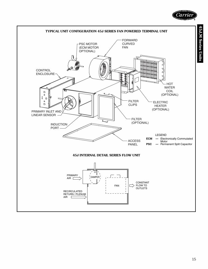
DAMPER
RECIRCULATEDRETURN / PLENUMAIR
CONSTANTFLOW TOOUTLETS
FAN
PRIMARYAIR
PSC MOTOR (ECM MOTOROPTIONAL)
FORWARDCURVEDFAN
CONTROLENCLOSURE
PRIMARY INLET ANDLINEAR SENSOR
INDUCTIONPORT
ACCESSPANEL
FILTER(OPTIONAL)
FILTERCLIPS
ELECTRICHEATER
(OPTIONAL)
HOTWATER
COIL(OPTIONAL)
TYPICAL UNIT CONFIGURATION 45J SERIES FAN POWERED TERMINAL UNIT
45J INTERNAL DETAIL SERIES FLOW UNIT
a45-487
LEGENDECM — Electronically Commutated
MotorPSC — Permanent Split Capacitor

16
45J,
M S
erie
s U
nits
DAMPER
BACKDRAFTDAMPER
RECIRCULATEDRETURN / PLENUMAIR
VARIABLEFLOW TOOUTLETS
FAN
PRIMARYAIR
FORWARD CURVED FAN PSC MOTOR
BACKDRAFTDAMPER
CONTROLENCLOSURE
HOTWATER
COIL(OPTIONAL)
ELECTRICHEATER
(OPTIONAL)
FILTER(OPTIONAL)
ACCESS PANEL
PRIMARYINLET ANDLINEARSENSOR
FILTERCLIPS
INDUCTIONPORT
TYPICAL UNIT CONFIGURATION 45M PARALLEL FAN POWERED TERMINAL UNIT
45M INTERNAL DETAIL PARALLEL FLOW UNIT
a45-488
PSC — Permanent Split Capacitor
Physical data (cont)

17
45
J,M S
eries Units
X
D
HB
1"Z
W
Y A
INLET VIEW
1/2"
ALLOW AT LEAST 36"CLEARANCE FOR CONTROLSAND PER NEC REQUIREMENTS
6 1/4"
HANGER BRACKET - (4 PLACES)
RECIRCULATEDAIR INLETPRIMARY
AIR INLET
DD
DISCHARGE
34"
20"
17"
PLAN VIEW – LEFT HAND BOXCONTROLS AND SENSORS NOT SHOWN
7 1/2"
1-5/16"
G 6"
CONTROLENCLOSURESEE NOTE 3
11 7/8"
15"
DISCHARGE VIEW
1/2" DIAMETERDAMPER SHAFT
CONTROLENCLOSURESEE NOTE 2
45J SERIES FAN POWERED VAV TERMINALS — SIZES 2-6
LEGEND
NOTES:1. Dimensions are given in inches.2. Available in left hand primary air configuration only (control enclosure available in left hand only).3. Digital or analog control enclosure: 20 in. x 117/8 in., Pneumatic enclosure: 17 in. x 15 in.
DD — Linear Averaging Sensor/Inlet (Inlet Sizes 6-10 DD = 37/8 in.; 12-14 DD = 57/8 in.)NEC — National Electrical Code
UNITSIZE
PRI.CFM
FANCFM HP INLET
SIZE W HRECIRC. AIR
D G X Y ZA B
2 515 560 1/10 6 21 15 9 13 57/8 63/4 71/2 53/8 1
3515 990 1/4 6 21 15 9 13 57/8 91/4 71/2 53/8 1
920 990 1/4 8 21 15 9 13 77/8 91/4 71/2 53/8 1
4920 1440 1/4 8 321/4 173/4 143/8 15 77/8 117/8 87/8 73/8 13/8
1430 1440 1/4 10 321/4 173/4 143/8 15 97/8 117/8 87/8 73/8 13/8
51430 2100 1/2 10 321/4 173/4 143/8 15 97/8 131/8 87/8 73/8 13/82060 2100 1/2 12 321/4 173/4 143/8 15 117/8 131/8 87/8 83/8 13/8
62060 2530 3/4 12 321/4 173/4 143/8 15 117/8 131/8 87/8 83/8 13/82530 2530 3/4 14 321/4 173/4 143/8 15 137/8 131/8 87/8 83/8 13/8
Dimensions

18
45J,
M S
erie
s U
nits
10"
1 3/4"
11"
32"
15"11 7/8"
DISCHARGE VIEW
1 1/2"
15"
52"
1 1/4" TYP15"
18"
9"
15 7/8"
26"
INLET VIEW
39 1/8"
20"
17"
ALLOW AT LEAST 36"CLEARANCE FOR CONTROLS DISCHARGE
DD
6 1/4"
RECIRCULATEDAIR INLET
1/2"
DISCHARGE
HANGER BRACKET - (4 PLACES)
CONTROLENCLOSURESEE NOTE 2
CONTROLENCLOSURESEE NOTE 2
1/2" DIAMETERDAMPER SHAFT RECIRCULATED
AIR INLET PRIMARYAIR INLET
PLAN VIEW - LEFT HAND BOXCONTROLS AND SENSORS NOT SHOWN
DISCHARGEOUTLETSEE NOTE 3
45J SERIES FAN POWERED VAV TERMINALS — SIZE 7
LEGENDDD — Linear Averaging Sensor/Inlet (Inlet Size 16 DD = 57/8 in.)
NOTES: 1. Dimensions are given in inches.2. Digital or analog control enclosure: 20 in. x 117/8 in., Pneumatic
enclosure: 17 in. x 15 in.3. Discharge outlet dimensions: 32 in. x 11 in.
UNITSIZE
PRIMARYCFM
FANCFM
MOTOR HP (Qty)
INLETSIZE
7 3660 3900 3/4 (2) 16
Dimensions (cont)

19
45
J,M S
eries Units
PLAN VIEW – LEFT HAND BOXCONTROLS AND SENSORS NOT SHOWN
INLET VIEW DISCHARGE VIEW
45J SERIES FAN POWERED VAV TERMINALS WITH ELECTRIC HEAT — SIZES 2-6
LEGEND
NOTES:1. Dimensions are given in inches.2. Available in left hand primary air configuration only (control enclusure available in left hand only).3. Digital or analog control enclosure: 31 in. x 117/8 in., Pneumatic enclosure: 17 in. x 15 in.
DD — Linear Averaging Sensor/Inlet (Inlet Sizes 6-10 DD = 37/8 in.; 12-16 DD = 57/8 in.)NEC — National Electrical Code
UNITSIZE
PRI.CFM
FANCFM HP INLET
SIZE W HRECIRC. AIR
DDISCHARGE
X Y ZA B F G
2 515 560 1/10 6 21 15 9 13 57/8 11 11 71/2 53/8 1
3515 990 1/4 6 21 15 9 13 57/8 11 11 71/2 53/8 1
920 990 1/4 8 21 15 9 13 77/8 11 11 71/2 53/8 1
4920 1440 1/4 8 321/4 173/4 143/8 15 77/8 13 141/2 87/8 73/8 13/8
1430 1440 1/4 10 321/4 173/4 143/8 15 97/8 13 141/2 87/8 73/8 13/8
51430 2100 1/2 10 321/4 173/4 143/8 15 97/8 13 141/2 87/8 73/8 13/82060 2100 1/2 12 321/4 173/4 143/8 15 117/8 13 141/2 87/8 83/8 13/8
62060 2530 3/4 12 321/4 173/4 143/8 15 117/8 13 141/2 87/8 83/8 13/82530 2530 3/4 14 321/4 173/4 143/8 15 137/8 13 141/2 87/8 83/8 13/8

20
45J,
M S
erie
s U
nits
INLET VIEW
DISCHARGE VIEWPLAN VIEW – LEFT HAND BOX
HANGERBRACKET - (4PLCS)
CONTROLS ANS SENSORS NOT SHOWN
LEGEND
NOTES:1. Dimensions are given in inches.2. Available in left hand primary air configuration only (control enclusure available in left hand only).3. Digital or analog control enclosure: 31 in. x 117/8 in., Pneumatic enclosure: 17 in. x 15 in.
DD — Linear Averaging Sensor/Inlet (Inlet Sizes 6-10 DD = 37/8 in.; 12-16 DD = 57/8 in.)NEC — National Electrical Code
UNITSIZE
INLETSIZE
PRIMARYCFM
FANCFM HP
7 16 3660 3900 3/4 (2)
45J SERIES FAN POWERED VAV TERMINALS WITH ELECTRIC HEAT — SIZE 7
Dimensions (cont)

21
45
J,M S
eries Units
CONTROLS AND SENSORS NOT SHOWNPLAN VIEW – LEFT HAND CONTROLS & WATER CONNECTION
DISCHARGE VIEW
INLET VIEW
45J SERIES FAN POWERED VAV TERMINALS WITH HOT WATER HEAT — SIZES 2-6
LEGENDDD — Linear Averaging Sensor/
Inlet (Inlet Sizes 6-10DD= 37/8 in.;12-16 DD = 57/8 in.)
NOTES:1. Dimensions are given in inches.2. Available in left hand primary air configuration only.3. Digital or Analog control enclosure: 31 in. x 117/8 in., Pneumatic enclosure: 17 in. x 15 in.4. 61/6 in. long connection with vent and drain.
UNITSIZE
PRI.CFM
FANCFM HP INLET
SIZE W HRECIRC. AIR
DDISCHARGE
X Y Z1 ROW 2 ROW A B F G
2 515 540 525 1/10 6 21 15 9 13 57/8 121/2 15 71/2 53/8 1
3515 825 800 1/4 6 21 15 9 13 57/8 121/2 15 71/2 53/8 1920 875 800 1/4 8 21 15 9 13 77/8 121/2 15 71/2 53/8 1
4920 1440 1310 1/4 8 321/4 173/4 143/8 15 77/8 121/2 22 87/8 73/8 13/8
1430 1440 1310 1/4 10 321/4 173/4 143/8 15 97/8 121/2 22 87/8 73/8 13/8
51430 1960 1800 1/2 10 321/4 173/4 143/8 15 97/8 15 22 87/8 73/8 13/82060 1960 1800 1/2 12 321/4 173/4 143/8 15 117/8 15 22 87/8 83/8 13/8
62060 2425 2275 3/4 12 321/4 173/4 143/8 15 117/8 15 241/2 87/8 83/8 13/82530 2425 2275 3/4 14 321/4 173/4 143/8 15 137/8 15 241/2 87/8 83/8 13/8
22
45J,
M S
erie
s U
nits
15 7/8"
INLET VIEW
26"
15"
52"
18"
9"
15"
1 1/4" TYP1 1/2"
PLAN VIEW – LEFT HAND CONTROL AND COIL CONNECTIONCONTROLS AND SENSORS NOT SHOWN
(1 ROW) 8"(2 ROW) 9 3/16"
RECIRCULATEDAIR INLET
3"
17"
1/2"
20"
6 1/4"
PRIMARYAIR INLET
RECIRCULATEDAIR INLET
DD
DISCHARGE DISCHARGE
39 1/8"
DISCHARGE VIEW
CONTROLENCLOSURESEE NOTE 4
9"1" FLANGE(2 PLCS)
1/2" FLANGE(2 PLCS)
15"
34"
HOT WATER COIL
11 7/8"
15"
3/4"
HANGER BRACKET - (4 PLCS)
1/2" DIAMETERDAMPER SHAFT
CONTROLENCLOSURESEE NOTE 4
ALLOW AT LEAST 36”CLEARANCE FOR CONTROLS
SEE NOTE 5
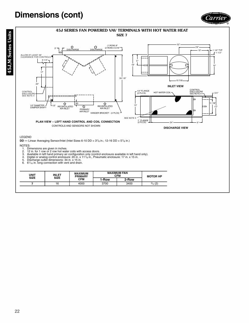
45J SERIES FAN POWERED VAV TERMINALS WITH HOT WATER HEATSIZE 7
LEGENDDD — Linear Averaging Sensor/Inlet (Inlet Sizes 6-10 DD = 37/8 in.; 12-16 DD = 57/8 in.)
NOTES:1. Dimensions are given in inches.2. 12 in. for 1 row or 2 row hot water coils with access doors.3. Available in left hand primary air configuration only (control enclosure available in left hand only).4. Digital or analog control enclosure: 20 in. x 117/8 in., Pneumatic enclosure: 17 in. x 15 in.5. Discharge outlet dimensions: 34 in. x 15 in.6. 61/16 in. long connection with vent and drain.
UNITSIZE
INLETSIZE
MAXIMUMPRIMARY
CFM
MAXIMUM FANCFM MOTOR HP
1-Row 2-Row7 16 4000 3700 3400 3/4 (2)
Dimensions (cont)

23
45
J,M S
eries Units
1" (25)
9 3/16"(233)
DISCHARGE
FIN DEPTH 2 5/32" (55)
2 3/32"(53)
MOUNTING HOLESON THIS FLANGEDSIDE ONLY
H
HPLUS1" (25)
1/2" (13) FLANGE DIMENSION
FINHEIGHT
FIN LENGTH
WW PLUS 2" (51)
1" (25)
1 1/8" (29)
2 CONNECTIONS5/8" (16) O.D.
12 MOUNTINGHOLES 3/16" (5)
1 1/8" (29)
DISCHARGE
3" (76) * 3" (76) *
1 17/32"(39)
1" (25)
8"(203)
FIN DEPTH 1 5/64" (27)
MOUNTING HOLES ONTHIS FLANGED SIDE ONLY
1/2" (13)
HPLUS1" (25)
H
FINHEIGHT
FIN LENGTH
WW PLUS 2" (51)
1" (25)
1 3/16"(30)
2 CONNECTIONS5/8" (16) O.D.
12 MOUNTINGHOLES 3/16" (5)
13/16" (21)
WOR 2 ,WEIV POTWOR 1 ,WEIV POT
FRONT VIEW, 2 ROW FRONT VIEW, 1 ROW
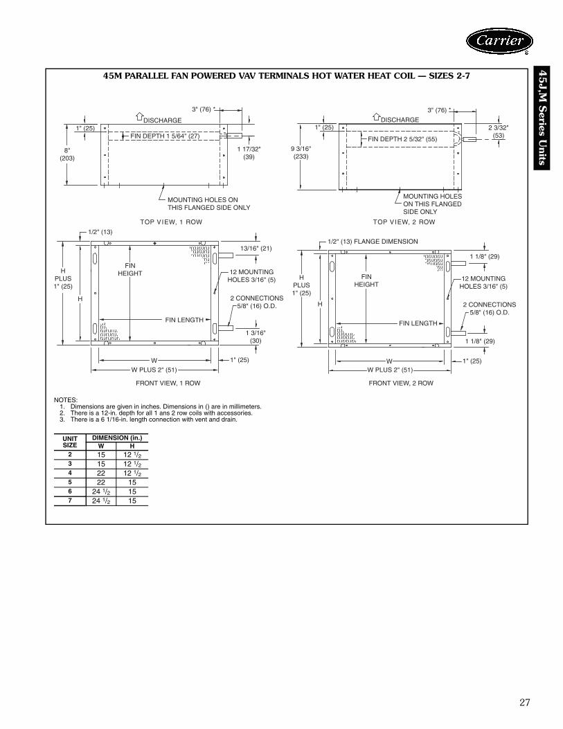
45J SERIES FAN POWERED VAV TERMINALS HOT WATER HEAT COIL — SIZES 2-7
NOTES:1. Dimensions are given in inches. Dimensions in () are in millimeters.2. There is a 12-in. depth for all 1 and 2 row coils with accessories.3. There is a 6 1/16-in. length connection with vent and drain.
UNITSIZE
DIMENSION (in.)W H
2 15 12 1/23 15 12 1/24 22 12 1/25 22 156 24 1/2 157 34 15
a45-489

24
45J,
M S
erie
s U
nits
F
Z
1 1/4"G
15"
11 7/8"
DISCHARGE VIEW
CONTROLENCLOSURESEE NOTE 2
W
X
D
Y A 3/4"
1"
B H
INLET VIEW
HANGER BRACKET - (4 PLCS)
BACKDRAFTDAMPER
PRIMARYAIR INLET
ALLOW AT LEAST 36"CLEARANCE FOR CONTROLS
1/2" DIAMETERDAMPER SHAFT
17"
20"
DD1/2"
6 1/4"DISCHARGE
RECIRCULATEDAIR INLET
34"
PLAN VIEW – LEFT HAND BOXCONTROLS AND SENSORS NOT SHOWN
45M PARALLEL FAN POWERED VAV TERMINALS — SIZES 2-7
LEGENDDD — Linear Averaging Sensor/Inlet (Inlet Sizes 6-10 DD = 37/8 in.; 12-16 DD = 57/8 in.)
NOTES:1. Dimensions are given in inches.2. Available in left hand primary air configuration only (control enclosure available in left hand only).3. Digital or analog control enclosure: 31 in. x 117/8 in., Pneumatic enclosure: 17 in. x 15 in.
UNITSIZE
PRI.CFM
FANCFM HP INLET
SIZE W HRECIRC. AIR
DDISCHARGE
X Y ZA B F G
2515 400 1/10 6 29 15 13 13 57/8 111/2 111/2 71/2 67/8 13/4920 400 1/10 8 29 15 13 13 77/8 111/2 111/2 71/2 67/8 13/4
3920 600 1/10 8 29 15 13 13 77/8 111/2 111/2 71/2 67/8 13/4
1430 600 1/10 10 29 15 13 13 97/8 111/2 111/2 71/2 67/8 13/4
41430 1050 1/4 10 29 15 13 13 97/8 111/2 111/2 71/2 67/8 13/42060 1050 1/4 12 29 15 13 13 117/8 111/2 111/2 71/2 67/8 13/4
52060 1500 1/2 12 37 173/4 17 153/4 117/8 14 151/2 87/8 9 17/82800 1500 1/2 14 37 173/4 17 153/4 137/8 14 151/2 87/8 9 17/8
62800 1800 1/2 14 37 173/4 17 153/4 137/8 14 151/2 87/8 9 17/83660 1800 1/2 16 37 173/4 17 153/4 157/8 14 151/2 87/8 9 17/8
7 3660 2200 3/4 16 37 173/4 17 153/4 157/8 14 151/2 87/8 9 17/8
Dimensions (cont)

25
45
J,M S
eries Units
ALLOW AT LEAST 24" CLEARANCEFOR REMOVAL OF HEATER RACK
UNINSULATEDHEATER CASING
DISCHARGE
PROVIDE36" MINIMUM ACCESSPER NEC REQUIREMENTS
6 1/4"9 3/4"
31"
17"
1/2"DIAMETERDAMPER SHAFT
1/2" DDPRIMARYAIR INLET
RECIRCULATEDAIR INLET
BACKDRAFTDAMPER
HANGERBRACKETS4 PLACES
34"
1" FLANGETYP G 1 1/4"
15"
11 7/8"F
Z
ELECTRICALHEAT ELEMENT
CONTROLENCLOSURE(SEE NOTE 2)
HEATER TERMINATIONENCLOSURE
X
Y A
D
B H
1"3/4"
CONTROL ENCLOSURE(SEE NOTE 2)
W
45M PARALLEL FAN POWERED VAV TERMINALS WITH ELECTRIC HEAT — SIZES 2-7
LEGENDDD — Linear Averaging Sensor/Inlet (Inlet Sizes 6-12 DD = 21/2 in.; 14-16 DD = 31/2 in.)NEC — National Electrical CodeNOTES:
1. Dimensions are given in inches.2. Available as left hand primary air configuration only (control enclosure available in left hand only).3. Digital or analog control enclosure: 29-in., pneumatic: 17-in.
UNITSIZE
PRI.CFM
FANCFM HP INLET
SIZE W HRECIRC. AIR
DDISCHARGE
X Y ZA B F G
2515 400 1/10 6 29 15 13 13 57/8 111/2 111/2 71/2 67/8 13/4920 400 1/10 8 29 15 13 13 77/8 111/2 111/2 71/2 67/8 13/4
3920 600 1/10 8 29 15 13 13 77/8 111/2 111/2 71/2 67/8 13/4
1430 600 1/10 10 29 15 13 13 97/8 111/2 111/2 71/2 67/8 13/4
41430 1050 1/4 10 29 15 13 13 97/8 111/2 111/2 71/2 67/8 13/42060 1050 1/4 12 29 15 13 13 117/8 111/2 111/2 71/2 67/8 13/4
52060 1500 1/2 12 37 173/4 17 153/4 117/8 14 151/2 87/8 9 17/82800 1500 1/2 14 37 173/4 17 153/4 137/8 14 151/2 87/8 9 17/8
62800 1800 1/2 14 37 173/4 17 153/4 137/8 14 151/2 87/8 9 17/83660 1800 1/2 16 37 173/4 17 153/4 157/8 14 151/2 87/8 9 17/8
7 3660 2200 3/4 16 37 173/4 17 153/4 157/8 14 151/2 87/8 9 17/8
PLAN VIEW — LEFT HAND BOX SHOWN(CONTROLS AND SENSORS NOT SHOWN)
INLET VIEW DISCHARGE VIEW

26
45J,
M S
erie
s U
nits
W
A
D
Y
X
HB
3/4"
1 "
INLET VIEW
HANGER BRACKET - (4 PLCS)
BACKDRAFTDAMPER
17"
1/2" DIAMETERDAMPER SHAFT
20"
DD
1/2"PRIMARYAIR INLET
ALLOW AT LEAST 36"CLEARANCE FOR CONTROLS
UNINSULATEDCOIL CASING
6 1/4"
3"
DISCHARGE
RECIRCULATEDAIR INLET
34"
PLAN VIEW – LEFT HAND BOXCONTROLS AND SENSORS NOT SHOWN
G
F
1/2" FLANGE(2 PLCS)
1" FLANGE(2 PLCS)
Z
11 7/8"
1 1/4"
15"
DISCHARGE VIEW
CONTROLENCLOSURESEE NOTE 4
SEE NOTE 3 SEE NOTE 4
(2 ROW) 9 3/16"(1 ROW) 8"
45M PARALLEL FAN POWERED VAV TERMINALS WITH HOT WATER HEAT — SIZES 2-7
LEGENDDD — Linear Averaging Sensor/Inlet (Inlet Sizes 6-12 DD = 21/2 in.; 14-16 DD = 31/2 in.)
NOTES:1. Dimensions are given in inches.2. Available in left hand primary air configuration only (control enclosure available in left hand only).3. 12-in. depth for all 1 and 2 row hot water coils with access doors.4. Digital or analog control enclosure: 20 in. x 117/8 in., Pneumatic enclosure: 17 in. x 15 in.5. Optional 61/16 in. long connection with vent and drain option.
UNITSIZE
PRI.CFM
FANCFM HP INLET
SIZE W HRECIRC. AIR
DDISCHARGE
X Y ZA B F G
2515 400 1/10 6 29 15 13 13 57/8 121/2 15 71/2 67/8 11/4920 400 1/10 8 29 15 13 13 77/8 121/2 15 71/2 67/8 11/4
3920 550 1/10 8 29 15 13 13 77/8 121/2 15 71/2 67/8 11/4
1430 550 1/10 10 29 15 13 13 97/8 121/2 15 71/2 67/8 11/4
41430 1000 1/4 10 29 15 13 13 97/8 121/2 22 71/2 67/8 11/42060 1000 1/4 12 29 15 13 13 117/8 121/2 22 71/2 67/8 11/4
52060 1400 1/4 12 37 173/4 17 153/4 117/8 15 22 87/8 9 11/22800 1400 1/2 14 37 173/4 17 153/4 137/8 15 22 87/8 9 11/2
62800 1700 1/2 14 37 173/4 17 153/4 137/8 15 241/2 87/8 9 11/23660 1700 1/2 16 37 173/4 17 153/4 157/8 15 241/2 87/8 9 11/2
7 3660 2000 3/4 16 37 173/4 17 153/4 157/8 15 241/2 87/8 9 11/2
Dimensions (cont)
27
45
J,M S
eries Units
1" (25)
9 3/16"(233)
DISCHARGE
FIN DEPTH 2 5/32" (55)
2 3/32"(53)
MOUNTING HOLESON THIS FLANGEDSIDE ONLY
H
HPLUS1" (25)
1/2" (13) FLANGE DIMENSION
FINHEIGHT
FIN LENGTH
WW PLUS 2" (51)
1" (25)
1 1/8" (29)
2 CONNECTIONS5/8" (16) O.D.
12 MOUNTINGHOLES 3/16" (5)
1 1/8" (29)
DISCHARGE
3" (76) * 3" (76) *
1 17/32"(39)
1" (25)
8"(203)
FIN DEPTH 1 5/64" (27)
MOUNTING HOLES ONTHIS FLANGED SIDE ONLY
1/2" (13)
HPLUS1" (25)
H
FINHEIGHT
FIN LENGTH
WW PLUS 2" (51)
1" (25)
1 3/16"(30)
2 CONNECTIONS5/8" (16) O.D.
12 MOUNTINGHOLES 3/16" (5)
13/16" (21)
WOR 2 ,WEIV POTWOR 1 ,WEIV POT
FRONT VIEW, 2 ROW FRONT VIEW, 1 ROW
45M PARALLEL FAN POWERED VAV TERMINALS HOT WATER HEAT COIL — SIZES 2-7
NOTES:1. Dimensions are given in inches. Dimensions in () are in millimeters.2. There is a 12-in. depth for all 1 ans 2 row coils with accessories.3. There is a 6 1/16-in. length connection with vent and drain.
UNITSIZE
DIMENSION (in.)W H
2 15 12 1/23 15 12 1/24 22 12 1/25 22 156 24 1/2 157 24 1/2 15
a45-490

28
45J,
M S
erie
s U
nits
UNIT CAPACITIES
45J SERIES FAN POWERED TERMINAL UNIT
45M PARALLEL FAN POWERED TERMINAL UNIT
LEGEND
*45J unit size 7 is not available with 120 v motor option.
NOTES:1. 45J maximum primary airflow (cfm) is set by the maximum
induced airflow, which may vary as a function of downstream pres-sure. Maximum airflow shown is based on the maximum inducedairflow (fan airflow) or 1.00 in. wg velocity pressure at inlet probe,whichever is less.
2. 45M maximum primary airflow (cfm) is based on 1.00 in. wg veloc-ity pressure signal (VP), per inlet size, using a standard linearaveraging sensor.
3. Minimum recommended primary airflow (cfm) is based on0.03 in. wg differential pressure of the linear inlet flow sensor, or0 airflow. 0.03 in. wg is equal to 15% to 20% of the nominal flowrating of the terminal. Less than 15% to 20% may result in greaterthan +5% control of box flow.
4. 45M maximum fan airflow (cfm) is based on 0.25 in. wg external(downstream) static pressure, and 45J maximum fan airflow isbased on 0.10 in. wg downstream static pressure (see pages 29and 34 for complete fan curves).
5. 45J or 45M minimum fan airflow (cfm) is based on maximum exter-nal (downstream) static pressure 0.60 in. wg.
6. Minimum primary airflow (cfm) listed is for all controls except CCNwhich is shown separately with lower available minimum cfm. SomeDDC controls supplied by others may have different limitations.
7. Do not select discharge temperature exceeding 120 F. In addition,ASHRAE recommends a maximum discharge temperature of 90 Fto avoid room air stratification when heating from the ceiling (2001Fundamentals, Chapter 32).
UNITSIZE
INLETSIZE(in.)
MOTORHP
MOTORAMPS FAN AIRFLOW (cfm) PRIMARY AIRFLOW (cfm)
120V 208/240V 277V Max Min Max Min Min CCN2 6 1/10 1.8 1.0 0.7 560 100 515 90 or 0 52 or 0
36
1/4 3.6 2.0 1.5990 300 515 90 or 0 52 or 0
8 990 300 920 170 or 0 93 or 0
48
1/4 5.0 2.8 2.11440 550 920 170 or 0 93 or 0
10 1440 550 1430 250 or 0 145 or 0
510
1/2 8.3 4.6 3.52100 1100 1430 250 or 0 145 or 0
12 2100 1100 2060 360 or 0 210 or 0
612
3/4 9.5 5.8 4.42530 1200 2060 360 or 0 210 or 0
14 2530 1200 2530 500 or 0 285 or 07* 16 (2) 3/4 N/A 13.2 9.9 3900 2100 3660 650 or 0 370 or 0
UNITSIZE
INLETSIZE(in.)
MOTORHP
MOTORAMPS
FAN AIRFLOW(cfm)
PRIMARY AIRFLOW(cfm)
MINIMUMOPERATINGPRESSURE
(in. wg)120V 208/240V 277V Max Min Max Min Min CCN No or EH 1 row HW 2 row HW
26
1/10 1.6 0.9 0.7400 50 515 90 or 0 52 or 0 .32 .37 .42
8 400 200 920 170 or 0 93 or 0 .33 .49 .64
38
1/10 2.0 1.2 0.9600 150 920 170 or 0 93 or 0 .33 .48 .56
10 600 300 1430 250 or 0 145 or 0 .35 .74 .94
410
1/4 3.2 1.9 1.41050 250 1430 250 or 0 145 or 0 .35 .52 .60
12 1050 480 2060 360 or 0 210 or 0 .36 .71 .88
512
1/2 7.3 4.1 3.11500 860 2060 360 or 0 210 or 0 .36 .60 .77
14 1500 860 2800 500 or 0 285 or 0 .34 .77 1.08
614
1/2 10.1 5.1 4.21800 930 2800 500 or 0 285 or 0 .34 .68 .92
16 1800 930 3660 650 or 0 370 or 0 .35 .94 1.367 16 3/4 9.5 5.8 4.4 2200 1140 3660 650 or 0 370 or 0 .35 .67 .89
ASHRAE — American Society of Heating, Refrigeration and Air Conditioning Engineers
CCN — Carrier Comfort Network®EH — Electric HeatHW — Hot Water Heat
Performance data
29
45
J,M S
eries Units
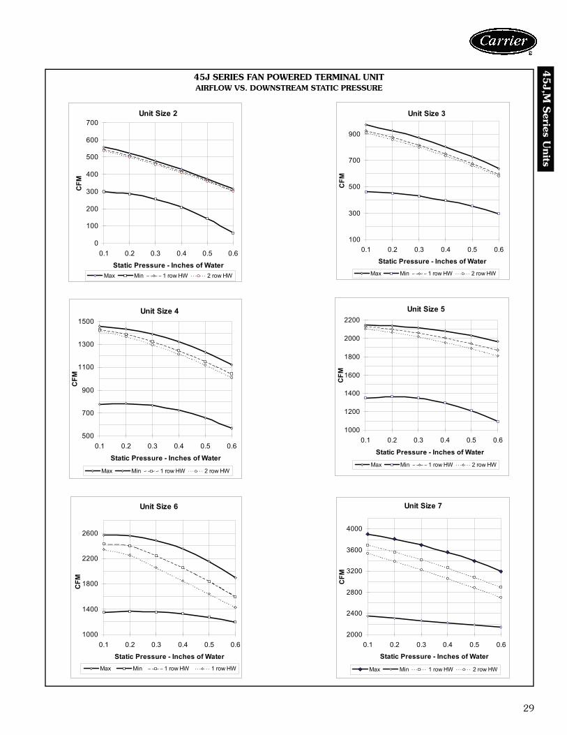
Unit Size 2
0
100
200
300
400
500
600
700
0.1 0.2 0.3 0.4 0.5 0.6
Static Pressure - Inches of Water
CFM
Max Min 1 row HW 2 row HW
45J SERIES FAN POWERED TERMINAL UNITAIRFLOW VS. DOWNSTREAM STATIC PRESSURE
Unit Size 3
100
300
500
700
900
0.1 0.2 0.3 0.4 0.5 0.6
Static Pressure - Inches of Water
CFM
Max Min 1 row HW 2 row HW
Unit Size 4
500
700
900
1100
1300
1500
0.1 0.2 0.3 0.4 0.5 0.6
Static Pressure - Inches of Water
CFM
Max Min 1 row HW 2 row HW
Unit Size 5
1000
1200
1400
1600
1800
2000
2200
0.1 0.2 0.3 0.4 0.5 0.6
Static Pressure - Inches of Water
CFM
Max Min 1 row HW 2 row HW
Unit Size 7
2000
2400
2800
3200
3600
4000
0.1 0.2 0.3 0.4 0.5 0.6
Static Pressure - Inches of Water
CFM
Max Min 1 row HW 2 row HW
Unit Size 6
1000
1400
1800
2200
2600
0.1 0.2 0.3 0.4 0.5 0.6
Static Pressure - Inches of Water
CFM
Max Min 1 row HW 1 row HW

30
45J,
M S
erie
s U
nits
45J SERIES FAN POWERED TERMINAL UNITDISCHARGE SOUND POWER DATA
LEGEND NOTES:1. ΔP is the difference in static pressure from inlet to discharge.2. Sound power levels are in decibels, re: 10-12 watts.3. End discharge sound power is the noise emitted from the unit discharge into the
duct.4. Discharge (external) static pressure is 0.25 in. wg.5. All sound data is based on tests conducted in accordance with ARI Standard
880-98.6. NC application data based on ARI 885-98 (2002 Addendum — Appendix E).
MODEL 45J SERIES FAN POWERED TERMINAL UNITAPPLICATION ASSUMPTIONS
UNITSIZE
INLETSIZE(in.)
FLOW RATE MIN ΔPsFAN ONLY FAN AND PRIMARY AT 0.5 ΔPs FAN AND PRIMARY AT 1.0 ΔPs
Octave Band Sound Power Lp Octave Band Sound Power Lp Octave Band Sound Power Lp
CFM L/s in. wg pa 2 3 4 5 6 7 NC 2 3 4 5 6 7 NC 2 3 4 5 6 7 NC
2 6
250 118 0.039 9.72 53 54 57 52 47 43 — 55 56 58 53 49 45 — 55 58 59 54 49 45 —
300 142 0.056 14.00 57 58 59 55 51 47 — 59 59 61 57 53 49 — 59 61 61 57 53 49 —
350 165 0.077 19.05 60 60 61 57 53 51 — 62 62 63 59 56 53 — 62 63 64 59 56 53 21
400 189 0.100 24.88 63 63 63 60 56 54 20 65 63 65 62 58 56 20 65 66 66 62 58 56 24
450 212 0.127 31.49 65 65 65 62 58 57 23 67 65 67 64 61 59 23 67 68 68 64 60 59 26
3 8
450 212 0.041 10.28 60 56 58 53 50 47 — 62 58 60 55 52 49 — 62 58 60 55 52 50 -
600 283 0.073 18.28 63 62 62 59 56 54 — 65 64 64 61 58 56 21 65 64 64 61 58 56 21
700 330 0.100 24.88 64 64 65 62 59 58 23 67 66 67 64 62 60 25 67 66 67 64 62 60 25
800 378 0.131 32.50 66 67 67 65 62 61 25 68 69 69 67 65 63 27 68 69 69 67 64 63 27
900 425 0.165 41.13 67 69 69 67 65 64 28 69 71 71 69 67 66 30 69 71 71 69 67 66 30
4 10
800 378 0.053 13.16 61 63 64 66 63 55 — 61 63 66 68 65 57 21 64 65 66 68 65 57 22
950 448 0.075 18.56 63 64 66 67 64 57 21 63 66 68 69 66 59 23 66 67 68 69 66 59 24
1100 519 0.100 24.88 64 66 68 67 65 59 23 64 67 70 69 67 61 25 68 68 70 70 67 61 26
1250 590 0.129 32.13 65 67 69 68 65 60 24 65 69 71 70 67 62 26 69 70 71 70 67 63 27
1400 661 0.162 40.31 67 68 71 68 65 62 26 67 70 71 70 68 63 28 70 71 73 70 68 64 29
5 12
1350 637 0.071 17.72 67 65 66 63 61 61 25 67 65 67 65 63 63 27 70 68 68 66 64 63 27
1525 720 0.091 22.61 69 67 68 66 64 64 28 69 67 70 68 66 66 30 72 71 70 69 67 66 30
1700 802 0.113 28.09 71 69 70 69 67 67 31 71 69 71 71 69 69 33 74 73 72 71 70 69 33
1875 885 0.137 34.17 72 71 71 72 70 69 33 72 71 73 72 72 72 35 75 75 74 74 72 72 35
2050 967 0.164 40.85 74 73 73 74 72 72 36 74 73 75 74 72 74 38 77 76 76 76 74 74 38
6 14
1400 661 0.044 11.06 68 68 63 60 58 57 26 70 70 64 62 60 59 28 70 70 65 62 60 59 28
1675 790 0.064 15.83 71 70 67 65 63 62 28 73 72 69 68 66 64 31 73 72 69 68 66 65 31
1950 920 0.086 21.46 74 72 70 70 68 67 31 76 74 72 72 70 69 33 76 74 72 72 70 69 33
2225 1050 0.112 27.93 76 74 73 74 72 71 35 78 76 75 76 74 73 36 78 76 75 76 74 73 36
2500 1180 0.142 35.27 78 75 76 77 75 74 38 80 78 78 79 77 74 38 80 78 78 79 77 76 40
7 16
2100 991 0.056 14.00 68 66 65 62 61 60 24 68 68 67 62 61 60 26 70 68 68 65 63 62 26
2675 1262 0.091 22.71 71 70 69 67 65 64 28 73 72 71 69 67 66 30 74 72 71 70 68 66 30
3050 1439 0.119 29.53 73 72 71 70 67 66 30 75 74 73 72 69 68 33 76 74 73 72 70 69 33
3425 1616 0.150 37.23 75 73 72 72 69 68 32 77 76 75 74 71 70 35 77 76 75 75 72 71 35
3800 1793 0.184 45.83 76 75 74 74 70 69 34 79 77 76 76 73 72 36 79 77 77 77 74 73 37
ARI — Air Conditioning and Refrigeration InstituteCFM — Air Volume (cubic feet per minute)Lp — Room Sound PressureMin ΔPs — MinimUm Operating Pressure Of The Primary Air ValueNC — ARI 880-98 Test Conditions— — Indicates an NC level less than 20
— SouNd Power Noise Criteria
ARI 885-98 OCTAVE BANDSDischarge < 300 cfm 2 3 4 5 6 7
Env Effect 2 1 0 0 0 0
Duct Lining, 5 ft, 8 x 8 x 1 in. 2 6 12 25 29 18
End Reflection 9 5 2 0 0 0
Power Division (0 outlets) 0 0 0 0 0 0
5 Ft, 8 in. Flex Duct 6 10 18 20 21 12
Space Effect 5 6 7 8 9 10
Total Attenuation 24 28 39 53 59 40
ARI 885-98 OCTAVE BANDSDischarge 300-700 cfm 2 3 4 5 6 7
Env Effect 2 1 0 0 0 0
Duct Lining, 5 ft, 12 x 12 x 1 in. 2 4 10 20 20 14
10 in. End Reflection 9 5 1 0 0 0
Power Division (2 outlets) 3 3 3 3 3 3
5 Ft, 8 in. Flex Duct 6 10 18 20 21 12
Space Effect 5 6 7 8 9 10
Total Attenuation 27 29 40 51 53 39
ARI 885-98 OCTAVE BANDSDischarge >700 cfm 2 3 4 5 6 7
Env Effect 2 1 0 0 0 0
Duct Lining, 5 ft, 15 x 15 x1 in. 2 3 9 18 17 12
End Reflection 9 5 2 0 0 0
Power Division (3 outlets) 5 5 5 5 5 5
5 Ft, 8 in. Flex Duct 6 10 18 20 21 12
Space Effect 5 6 7 8 9 10
Total Attenuation 29 30 41 51 52 39
Performance data (cont)

31
45
J,M S
eries Units
45J SERIES FAN POWERED TERMINAL UNIT (cont)RADIATED SOUND POWER DATA
LEGEND NOTES:1. ΔP is the difference in static pressure from inlet to discharge.2. Sound power levels are in decibels, re: 10-12 watts.3. Radiated sound power is the noise emitted from the unit casing and induction port.4. Discharge (external) static pressure is 0.25 in. wg.5. All sound data is based on tests conducted in accordance with ARI Standard
880-98.6. NC application data based on ARI 885-98 (2002 Addendum — Appendix E).
MODEL 45J SERIES FAN POWERED TERMINAL UNITAPPLICATION ASSUMPTIONS
UNITSIZE
INLETSIZE(in.)
FLOW RATE MIN ΔPsFAN ONLY FAN AND PRIMARY AT 0.5 ΔPs FAN AND PRIMARY AT 1.0 ΔPs
Octave Band Sound Power Lp Octave Band Sound Power Lp Octave Band Sound Power Lp
CFM L/s in. wg pa 2 3 4 5 6 7 NC 2 3 4 5 6 7 NC 2 3 4 5 6 7 NC
2 6
250 118 0.039 9.72 58 57 53 44 40 36 27 61 60 55 47 42 39 30 62 63 58 49 45 41 33
300 142 0.056 14.00 60 59 54 46 41 37 29 63 62 57 49 44 41 32 65 65 60 51 47 44 36
350 165 0.077 19.05 62 60 55 49 43 39 30 65 64 58 51 46 43 34 67 67 61 53 49 45 38
400 189 0.100 24.88 63 62 56 51 44 40 31 66 65 59 53 47 44 36 68 69 63 55 50 47 40
450 212 0.127 31.49 64 63 56 53 45 41 33 68 67 60 54 49 45 38 70 70 64 56 51 48 42
3 8
450 212 0.041 10.28 50 50 50 47 35 31 24 58 57 53 49 42 39 28 64 63 58 51 46 42 33
600 283 0.073 18.28 57 57 54 51 41 38 29 62 62 57 54 47 44 32 67 67 61 56 50 47 37
700 330 0.100 24.88 61 60 57 53 45 42 32 64 64 59 56 49 47 34 69 69 63 58 52 49 40
800 378 0.131 32.50 64 63 59 55 48 45 34 66 66 61 58 52 50 37 70 70 65 61 54 52 42
900 425 0.165 41.13 67 66 61 57 51 48 36 67 68 63 60 54 52 39 72 72 66 62 56 54 44
4 10
800 378 0.053 13.16 57 56 55 51 41 38 30 61 60 57 51 43 40 32 63 62 59 54 46 42 34
950 448 0.075 18.56 59 58 56 52 44 40 30 64 63 58 54 46 43 33 66 65 61 55 48 45 36
1100 519 0.100 24.88 61 60 57 53 46 42 31 66 65 59 55 48 45 36 68 67 62 57 50 47 38
1250 590 0.129 32.13 63 62 57 53 48 44 32 68 68 61 56 48 47 38 71 70 63 58 52 49 41
1400 661 0.162 40.31 65 63 58 54 50 46 33 70 69 62 57 50 48 41 72 72 65 59 54 51 43
5 12
1350 637 0.071 17.72 68 64 54 49 45 41 34 73 69 61 54 50 48 40 75 71 64 57 52 49 42
1525 720 0.091 22.61 69 65 56 51 48 44 35 75 70 62 56 52 49 41 76 72 65 58 54 51 44
1700 802 0.113 28.09 71 66 58 54 50 47 36 76 71 63 57 54 51 43 78 73 67 60 55 52 45
1875 885 0.137 34.17 72 66 59 55 52 49 38 77 72 65 58 55 53 44 79 74 68 61 57 54 47
2050 967 0.164 40.85 73 67 61 57 54 51 39 78 73 66 60 57 54 45 80 75 69 62 58 55 48
6 14
1400 661 0.044 11.06 68 63 55 51 47 43 33 71 67 59 53 49 47 37 73 69 62 56 51 49 40
1675 790 0.064 15.83 71 66 58 54 50 47 37 74 70 62 56 53 50 41 75 72 65 59 55 53 43
1950 920 0.086 21.46 74 68 60 57 53 50 40 76 72 65 59 56 54 44 78 74 68 61 58 56 46
2225 1050 0.112 27.93 76 70 62 59 56 53 43 78 74 67 59 58 57 47 80 77 70 63 61 59 49
2500 1180 0.142 35.27 78 72 64 62 58 56 45 80 76 69 62 61 59 49 82 79 72 65 63 62 51
7 16
2100 991 0.056 14.00 66 64 59 55 50 47 34 71 68 63 59 55 51 39 74 72 67 63 58 55 43
2675 1262 0.091 22.71 70 67 63 59 54 52 38 74 71 66 62 58 55 42 77 74 70 65 61 58 46
3050 1439 0.119 29.53 72 69 65 62 57 55 40 76 73 68 64 60 57 44 78 76 71 67 63 60 48
3425 1616 0.150 37.23 74 71 67 63 59 57 42 77 74 69 65 62 59 46 80 77 72 68 64 62 50
3800 1793 0.184 45.83 76 72 68 65 61 59 44 79 75 71 65 63 61 48 81 78 74 69 66 64 51
ARI — Air Conditioning and Refrigeration InstituteCFM — Air Volume (cubic feet per minute)Lp — Room Sound PressureMin ΔPs — Minimum Operating Pressure Of The Primary Air ValueNC — ARI 880-98 Test Conditions— — Indicates an NC level less than 20
— Sound Power Noise Criteria
ARI 885-98OCTAVE BANDS
2 3 4 5 6 7
Mineral Tile Space/Ceiling Effect 16 18 20 26 31 36
Environ. Effect 2 1 0 0 0 0
Total Attenuation 18 19 20 26 31 36

32
45J,
M S
erie
s U
nits
ARI CERTIFICATION RATINGS FOR 45J SERIES FAN POWERED TERMINAL UNIT
ARI CERTIFICATION RATINGS FOR AIR TERMINALS (RADIATED)
ARI CERTIFICATION RATINGS FOR AIR TERMINALS (DISCHARGE)
Notes for Sound Data Tables:Air Conditioning and Refrigeration Institute (ARI) andASHRAE (American Society of Heating, Refrigeration andAir Conditioning Engineers) provide guidance in bothmeasuring sound power levels (per ARI 880-98), and inestimating the resultant room sound pressure, typicallyshown as an NC level (per ARI 885-98 — 2002 addendum— Appendix E). American Society of Heating, Refrigera-tion and Air Conditioning Engineers (ASHRAE) handbooksprovide detailed acoustical guidance. Air Conditioning andRefrigeration Institute (ARI) Standard 885 is an applicationstandard which provides tables and equations for
determining acoustical deduction based on the ASHRAEguides, as well as additional information provided by man-ufacturers.
All sound data shown by octave bands is raw data with-out any corrections for room absorption or duct attenua-tion. This Sound Power data is tested in accordance withARI Standard 880-98.
Accurate sound level estimates for typical office spacesor other applications are reflected by NC values. TheseNC levels are calculated based on procedures from ARIStandard 885-98.
CORRECTION FACTORS FOR OTHER ENTERING CONDITIONS
NOTE: Do not select for discharge temperatures exceeding 120 F. Inaddition, ASHRAE recommends a maximum discharge temperature of
90 F to avoid room air temperature stratification when heating from theceiling (2001 Fundamentals, Chapter 32).
UNIT SIZE
FAN PRIMARY CFM MIN. Ps
FAN ONLY SOUND POWER FAN PLUS PRIMARY AT 1.5 in. INLET
Octave Bands Octave BandsCFM Watts 2 3 4 5 6 7 2 3 4 5 6 7
2 400 200 400 0.1 63 63 57 52 45 42 70 72 65 57 52 493 700 380 700 0.1 64 63 58 54 46 43 73 75 66 60 54 504 1100 520 1100 0.1 67 64 60 55 48 44 75 75 67 61 55 515 1600 945 1600 0.1 72 68 63 58 52 48 78 76 68 62 56 526 2100 1100 2100 0.1 75 71 64 62 57 54 80 78 71 67 61 597 2800 2770 2800 0.1 77 74 68 63 59 56 82 81 76 69 64 62
UNITSIZE
FANFAN ONLY SOUND POWER
Octave BandsCFM Watts 2 3 4 5 6 7
2 400 200 64 64 65 61 57 553 700 380 66 66 65 63 61 604 1100 520 66 66 68 68 66 655 1600 945 71 70 70 69 68 686 2100 1100 73 73 74 74 71 717 2800 2770 78 76 74 73 70 70
ΔT 50 60 70 80 90 100 115 125 140 150Factor 0.44 0.52 0.61 0.70 0.79 0.88 1.00 1.07 1.20 1.30
Performance data (cont)

33
45
J,M S
eries Units
45J SERIES FAN POWERED TERMINAL UNITHOT WATER COIL DATA CAPACITIES
PS — Static Pressure Drop (in.)NOTES:
1. Hot water coil capacities are in MBtuh (MBtuh = 1000 Btuh).2. Btuh = 1.08 x cfm x ΔT (Temp rise across coil).3. Data is based upon 180 F entering water and 55 F entering air.4. Head Loss is measured in feet of water.5. Tables are based upon a temperature difference of 115 F between entering air and entering
water. For other temperature differences, multiply MBtuh values by the Correction Factorstable on page 32.
6. LAT (Leaving Air Temperature) = Entering Air Temp + air temp rise.7. Air temperature rise = 927 x MBtuh/cfm.8. Water temperature drop = 2.04 x MBtuh/gpm.9. Connections: All coils are 5/8-in. OD male solder.
10. Coils are not for steam application. Contact your Carrier representative for steam coil data.11. Do not select for discharge temperatures exceeding 120 F. In addition, ASHRAE recom-
mends a maximum discharge temperature of 95 F to avoid room air stratification whenheating from the ceiling (2001 Fundamentals, Chapter 32.)
UNITSIZE ROWS FLOW RATE
(Gpm)HEADLOSS
AIRFLOW (cfm)300 330 360 390 420 450 480 510 540
2 One Row
1.0 0.20 11.9 12.3 12.6 13.0 13.2 13.6 14.0 14.3 14.72.0 0.70 13.3 13.8 14.2 14.6 15.0 15.5 16.0 16.5 16.94.0 2.50 14.1 14.7 15.2 15.7 16.1 16.7 17.3 17.9 18.46.0 5.20 14.5 15.1 15.6 16.1 16.5 17.2 17.8 18.4 19.0
Airside Δ PS 0.02 0.02 0.03 0.03 0.04 0.04 0.04 0.05 0.05
2 Two Rows
1.0 0.50 19.3 20.2 21.1 21.9 22.7 23.4 24.1 24.7 25.33.0 3.30 22.7 24.2 25.5 26.8 28.1 29.2 30.3 31.4 32.44.0 5.50 23.3 24.8 26.2 27.6 28.9 30.1 31.3 32.5 33.65.0 8.20 23.6 25.2 26.6 28.1 29.4 30.7 32.0 33.2 34.3
Airside Δ PS 0.04 0.04 0.05 0.06 0.07 0.07 0.08 0.09 0.10
UNITSIZE ROWS FLOW RATE
(Gpm)HEADLOSS
AIRFLOW (cfm)450 505 560 615 670 725 780 835 890
3 One Row
1.0 0.20 13.6 14.3 14.9 15.5 16.0 16.5 16.9 17.3 17.72.0 0.70 15.5 16.4 17.2 18.0 18.7 19.4 20.0 20.6 21.24.0 2.50 16.7 17.8 18.8 19.7 20.6 21.4 22.2 22.9 23.66.0 5.20 17.2 18.3 19.4 20.4 21.3 22.2 23.0 23.8 24.6
Airside Δ PS 0.04 0.05 0.06 0.07 0.08 0.09 0.10 0.12 0.13
3 Two Rows
1.0 0.50 23.4 24.6 25.6 26.6 27.4 28.2 28.9 29.5 30.13.0 3.30 29.2 31.2 33.1 34.8 36.4 37.9 39.3 40.6 41.94.0 5.50 30.1 32.3 34.3 36.2 37.9 39.6 41.1 42.6 44.05.0 8.20 30.7 33.0 35.1 37.1 38.9 40.7 42.3 43.9 45.4
Airside Δ PS 0.07 0.09 0.11 0.13 0.15 0.17 0.20 0.22 0.25
UNITSIZE ROWS FLOW RATE
(Gpm)HEADLOSS
AIRFLOW (cfm)800 875 950 1025 1100 1175 1250 1325 1400
4 One Row
1.0 0.20 20.3 21.0 21.6 22.2 22.7 23.2 23.7 24.1 24.52.0 0.80 24.1 25.1 26.0 26.9 27.7 28.5 29.2 29.9 30.54.0 2.90 26.6 27.9 29.0 30.1 31.2 32.2 33.1 34.0 34.86.0 5.90 27.6 29.0 30.2 31.4 32.6 33.7 34.7 35.7 36.6
Airside Δ PS 0.06 0.07 0.08 0.09 0.10 0.11 0.12 0.14 0.15
4 Two Rows
1.0 0.50 33.4 34.4 35.3 36.1 36.8 37.5 38.1 38.6 39.13.0 3.70 46.0 48.2 50.2 52.1 53.9 55.5 57.1 58.6 60.04.0 6.20 48.1 50.5 52.8 54.9 56.9 58.8 60.6 62.3 64.05.0 9.20 49.5 52.1 54.5 56.8 58.9 61.0 63.0 64.8 66.6
Airside Δ PS 0.11 0.12 0.14 0.16 0.19 0.21 0.23 0.26 0.28
UNITSIZE ROWS FLOW RATE
(Gpm)HEADLOSS
AIRFLOW (cfm)1400 1480 1560 1640 1720 1800 1880 1960 2040
5 One Row
1.0 0.30 26.7 27.1 27.5 27.9 28.3 28.7 29.0 29.3 29.62.0 1.00 33.3 34.0 34.7 35.4 36.0 36.6 37.2 37.8 38.34.0 3.50 38.0 39.0 39.9 40.8 41.7 42.6 43.4 44.1 44.96.0 7.20 40.0 41.1 42.1 43.1 44.1 45.0 45.9 46.8 47.7
Airside Δ PS 0.11 0.12 0.13 0.14 0.15 0.17 0.18 0.19 0.21
5 Two Rows
1.0 0.60 41.5 42.0 42.5 42.9 43.3 43.7 44.1 44.4 44.73.0 4.50 64.5 66.1 67.5 69.0 70.3 71.6 72.8 74.0 75.14.0 7.50 68.8 70.7 72.4 74.1 75.7 77.2 78.6 80.0 81.45.0 11.20 71.7 73.7 75.6 77.5 79.2 80.9 82.5 84.1 85.6
Airside Δ PS 0.20 0.22 0.25 0.27 0.29 0.32 0.34 0.37 0.40
UNITSIZE ROWS FLOW RATE
(Gpm)HEADLOSS
AIRFLOW (cfm)1400 1525 1640 1760 1880 2000 2120 2240 2360
6 One Row
1.0 0.30 27.9 28.6 29.2 29.8 30.4 30.9 31.3 31.8 32.22.0 1.10 34.9 36.1 37.1 38.1 39.1 40.0 40.8 41.6 42.34.0 3.70 39.9 41.5 42.9 44.3 45.6 46.8 48.0 49.1 50.26.0 7.50 42.0 43.7 45.3 46.9 48.3 49.7 51.1 52.3 53.6
Airside Δ PS 0.09 0.10 0.12 0.13 0.15 0.17 0.19 0.20 0.22
6 Two Rows
1.0 0.70 42.7 43.5 44.2 44.8 45.4 45.9 46.3 46.7 47.13.0 4.70 67.1 69.5 71.8 73.9 75.9 77.7 79.4 81.0 82.64.0 7.80 71.7 74.5 77.2 79.7 82.1 84.3 86.3 88.3 90.25.0 11.60 74.6 77.8 80.8 83.5 86.2 88.6 91.0 93.2 95.3
Airside Δ PS 0.17 0.20 0.22 0.25 0.28 0.32 0.35 0.39 0.42
UNITSIZE ROWS FLOW RATE
(Gpm)HEADLOSS
AIRFLOW (cfm)1800 1950 2100 2250 2400 2550 2700 2850 3000
7 One Row
1.0 0.40 34.0 34.8 35.5 36.1 36.6 37.2 37.6 38.1 38.52.0 1.20 44.3 45.6 46.9 48.1 49.2 50.2 51.1 52.1 52.94.0 4.20 51.8 53.7 55.5 57.2 58.8 60.3 61.8 63.2 64.56.0 8.60 54.9 57.0 59.1 61.1 62.9 64.7 66.4 68.0 69.5
Airside Δ PS 0.08 0.09 0.10 0.12 0.13 0.14 0.16 0.17 0.19
7 Two Rows
1.0 0.80 48.6 49.2 49.7 50.2 50.6 51.0 51.3 51.6 51.93.0 5.30 83.7 86.5 89.0 91.3 93.5 95.5 97.3 99.1 100.74.0 8.90 90.7 94.1 97.2 100.1 102.8 105.3 107.7 109.9 112.05.0 13.20 95.3 99.1 102.6 105.9 109.0 112.0 114.7 117.3 119.8
Airside Δ PS 0.15 0.17 0.19 0.22 0.24 0.27 0.30 0.33 0.36

34
45J,
M S
erie
s U
nits 45M PARALLEL FAN POWERED TERMINAL UNIT
FAN CURVES
Unit Size 2
0
100
200
300
400
500
600
0.1 0.2 0.3 0.4 0.5 0.6
Static Pressure - Inches of Water
CFM
Max Min 1 Row HW 2 Row HW
Unit Size 4
100200300400500600700800900
1000110012001300
0.1 0.2 0.3 0.4 0.5 0.6
Static Pressure - Inches of Water
CFM
Max Min 1 Row HW 2 Row HW
Unit Size 6
400
600
800
1000
1200
1400
1600
1800
2000
0.1 0.2 0.3 0.4 0.5 0.6
Static Pressure - Inches of Water
CFM
Max Min 1 Row Coil 2 Row Coil
Unit Size 7
700
900
1100
1300
1500
1700
1900
2100
2300
2500
0.1 0.2 0.3 0.4 0.5 0.6
Static Pressure - Inches of Water
CFM
Max Min 1 Row Coil 2 Row Coil
Unit Size 3
100
200
300
400
500
600
700
800
0.1 0.2 0.3 0.4 0.5 0.6
Static Pressure - Inches of Water
CFM
Max Min 1 Row HW 2 Row HW
Unit Size 5
400
600
800
1000
1200
1400
1600
1800
2000
0.1 0.2 0.3 0.4 0.5 0.6
Static Pressure - Inches of Water
CFM
Max Min 1 Row HW 2 Row HW
Performance data (cont)
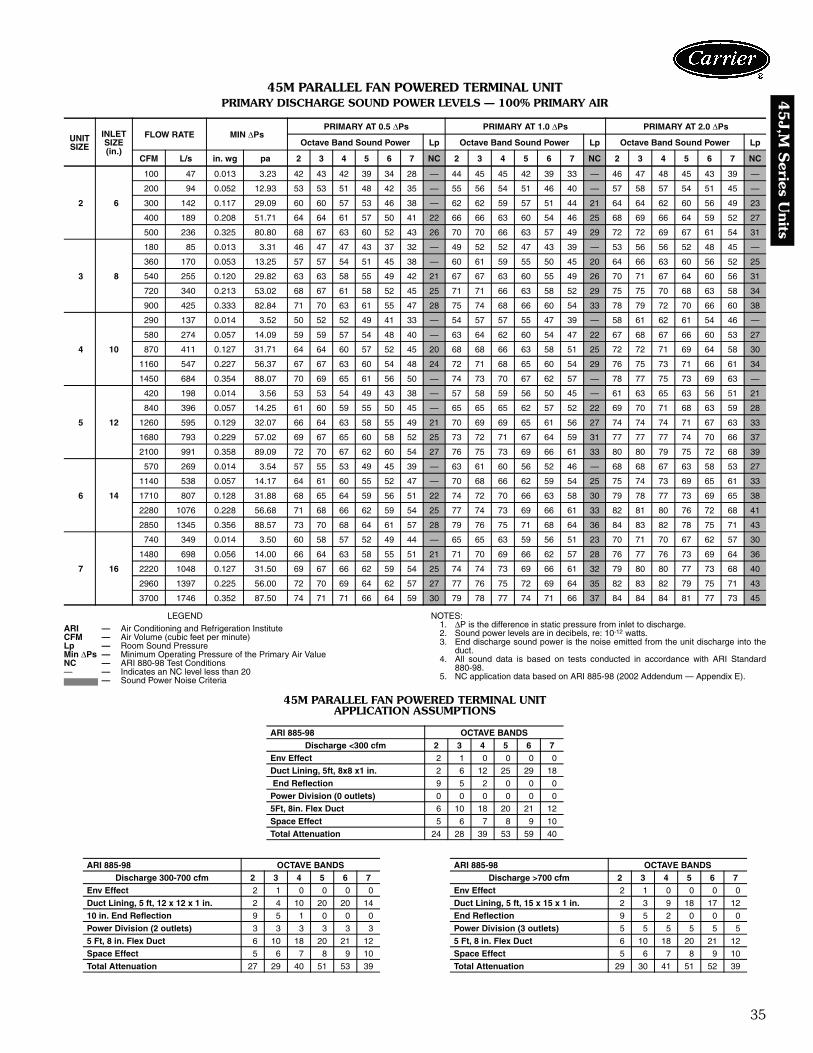
35
45
J,M S
eries Units
45M PARALLEL FAN POWERED TERMINAL UNITPRIMARY DISCHARGE SOUND POWER LEVELS — 100% PRIMARY AIR
LEGEND NOTES:1. ΔP is the difference in static pressure from inlet to discharge.2. Sound power levels are in decibels, re: 10-12 watts.3. End discharge sound power is the noise emitted from the unit discharge into the
duct.4. All sound data is based on tests conducted in accordance with ARI Standard
880-98.5. NC application data based on ARI 885-98 (2002 Addendum — Appendix E).
45M PARALLEL FAN POWERED TERMINAL UNIT APPLICATION ASSUMPTIONS
UNIT SIZE
INLET SIZE(in.)
FLOW RATE MIN ΔPsPRIMARY AT 0.5 ΔPs PRIMARY AT 1.0 ΔPs PRIMARY AT 2.0 ΔPs
Octave Band Sound Power Lp Octave Band Sound Power Lp Octave Band Sound Power Lp
CFM L/s in. wg pa 2 3 4 5 6 7 NC 2 3 4 5 6 7 NC 2 3 4 5 6 7 NC
2 6
100 47 0.013 3.23 42 43 42 39 34 28 — 44 45 45 42 39 33 — 46 47 48 45 43 39 —
200 94 0.052 12.93 53 53 51 48 42 35 — 55 56 54 51 46 40 — 57 58 57 54 51 45 —
300 142 0.117 29.09 60 60 57 53 46 38 — 62 62 59 57 51 44 21 64 64 62 60 56 49 23
400 189 0.208 51.71 64 64 61 57 50 41 22 66 66 63 60 54 46 25 68 69 66 64 59 52 27
500 236 0.325 80.80 68 67 63 60 52 43 26 70 70 66 63 57 49 29 72 72 69 67 61 54 31
3 8
180 85 0.013 3.31 46 47 47 43 37 32 — 49 52 52 47 43 39 — 53 56 56 52 48 45 —
360 170 0.053 13.25 57 57 54 51 45 38 — 60 61 59 55 50 45 20 64 66 63 60 56 52 25
540 255 0.120 29.82 63 63 58 55 49 42 21 67 67 63 60 55 49 26 70 71 67 64 60 56 31
720 340 0.213 53.02 68 67 61 58 52 45 25 71 71 66 63 58 52 29 75 75 70 68 63 58 34
900 425 0.333 82.84 71 70 63 61 55 47 28 75 74 68 66 60 54 33 78 79 72 70 66 60 38
4 10
290 137 0.014 3.52 50 52 52 49 41 33 — 54 57 57 55 47 39 — 58 61 62 61 54 46 —
580 274 0.057 14.09 59 59 57 54 48 40 — 63 64 62 60 54 47 22 67 68 67 66 60 53 27
870 411 0.127 31.71 64 64 60 57 52 45 20 68 68 66 63 58 51 25 72 72 71 69 64 58 30
1160 547 0.227 56.37 67 67 63 60 54 48 24 72 71 68 65 60 54 29 76 75 73 71 66 61 34
1450 684 0.354 88.07 70 69 65 61 56 50 — 74 73 70 67 62 57 — 78 77 75 73 69 63 —
5 12
420 198 0.014 3.56 53 53 54 49 43 38 — 57 58 59 56 50 45 — 61 63 65 63 56 51 21
840 396 0.057 14.25 61 60 59 55 50 45 — 65 65 65 62 57 52 22 69 70 71 68 63 59 28
1260 595 0.129 32.07 66 64 63 58 55 49 21 70 69 69 65 61 56 27 74 74 74 71 67 63 33
1680 793 0.229 57.02 69 67 65 60 58 52 25 73 72 71 67 64 59 31 77 77 77 74 70 66 37
2100 991 0.358 89.09 72 70 67 62 60 54 27 76 75 73 69 66 61 33 80 80 79 75 72 68 39
6 14
570 269 0.014 3.54 57 55 53 49 45 39 — 63 61 60 56 52 46 — 68 68 67 63 58 53 27
1140 538 0.057 14.17 64 61 60 55 52 47 — 70 68 66 62 59 54 25 75 74 73 69 65 61 33
1710 807 0.128 31.88 68 65 64 59 56 51 22 74 72 70 66 63 58 30 79 78 77 73 69 65 38
2280 1076 0.228 56.68 71 68 66 62 59 54 25 77 74 73 69 66 61 33 82 81 80 76 72 68 41
2850 1345 0.356 88.57 73 70 68 64 61 57 28 79 76 75 71 68 64 36 84 83 82 78 75 71 43
7 16
740 349 0.014 3.50 60 58 57 52 49 44 — 65 65 63 59 56 51 23 70 71 70 67 62 57 30
1480 698 0.056 14.00 66 64 63 58 55 51 21 71 70 69 66 62 57 28 76 77 76 73 69 64 36
2220 1048 0.127 31.50 69 67 66 62 59 54 25 74 74 73 69 66 61 32 79 80 80 77 73 68 40
2960 1397 0.225 56.00 72 70 69 64 62 57 27 77 76 75 72 69 64 35 82 83 82 79 75 71 43
3700 1746 0.352 87.50 74 71 71 66 64 59 30 79 78 77 74 71 66 37 84 84 84 81 77 73 45
ARI — Air Conditioning and Refrigeration InstituteCFM — Air Volume (cubic feet per minute)Lp — Room Sound PressureMin ΔPs — Minimum Operating Pressure of the Primary Air ValueNC — ARI 880-98 Test Conditions— — Indicates an NC level less than 20
— Sound Power Noise Criteria
ARI 885-98 OCTAVE BANDSDischarge <300 cfm 2 3 4 5 6 7
Env Effect 2 1 0 0 0 0
Duct Lining, 5ft, 8x8 x1 in. 2 6 12 25 29 18
End Reflection 9 5 2 0 0 0
Power Division (0 outlets) 0 0 0 0 0 0
5Ft, 8in. Flex Duct 6 10 18 20 21 12
Space Effect 5 6 7 8 9 10
Total Attenuation 24 28 39 53 59 40
ARI 885-98 OCTAVE BANDSDischarge 300-700 cfm 2 3 4 5 6 7
Env Effect 2 1 0 0 0 0
Duct Lining, 5 ft, 12 x 12 x 1 in. 2 4 10 20 20 14
10 in. End Reflection 9 5 1 0 0 0
Power Division (2 outlets) 3 3 3 3 3 3
5 Ft, 8 in. Flex Duct 6 10 18 20 21 12
Space Effect 5 6 7 8 9 10
Total Attenuation 27 29 40 51 53 39
ARI 885-98 OCTAVE BANDSDischarge >700 cfm 2 3 4 5 6 7
Env Effect 2 1 0 0 0 0
Duct Lining, 5 ft, 15 x 15 x 1 in. 2 3 9 18 17 12
End Reflection 9 5 2 0 0 0
Power Division (3 outlets) 5 5 5 5 5 5
5 Ft, 8 in. Flex Duct 6 10 18 20 21 12
Space Effect 5 6 7 8 9 10
Total Attenuation 29 30 41 51 52 39
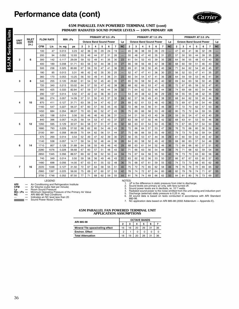
36
45J,
M S
erie
s U
nits
45M PARALLEL FAN POWERED TERMINAL UNIT (cont)PRIMARY RADIATED SOUND POWER LEVELS — 100% PRIMARY AIR
LEGEND NOTES:1. ΔP is the difference in static pressure from inlet to discharge.2. Sound levels are primary air only, with fans turned off.3. Sound power levels are in decibels, re: 10-12 watts.4. Radiated sound power is the noise emitted from the unit casing and induction port5. Discharge (external) static pressure is 0.25 in. wg.6. All sound data is based on tests conducted in accordance with ARI Standard
880-98.7. NC application data based on ARI 885-98 (2002 Addendum — Appendix E).
45M PARALLEL FAN POWERED TERMINAL UNIT APPLICATION ASSUMPTIONS
UNIT SIZE
INLET SIZE(in.)
FLOW RATE MIN ΔPsPRIMARY AT 0.5 ΔPs PRIMARY AT 1.0 ΔPs PRIMARY AT 2.0 ΔPs
Octave Band Sound Power Lp Octave Band Sound Power Lp Octave Band Sound Power Lp
CFM L/s in. wg pa 2 3 4 5 6 7 NC 2 3 4 5 6 7 NC 2 3 4 5 6 7 NC
2 6
100 47 0.013 3.23 42 36 35 29 24 19 — 45 38 38 33 28 23 — 47 40 41 36 32 28 —
200 94 0.052 12.93 53 46 44 37 31 26 — 55 48 47 40 35 31 21 57 50 50 44 39 35 24
300 142 0.117 29.09 59 52 49 41 35 30 23 61 54 52 45 39 35 26 64 56 55 48 43 40 30
400 189 0.208 51.71 63 56 52 44 38 33 27 66 58 56 48 42 38 30 68 60 59 51 46 43 34
500 236 0.325 80.80 67 59 55 47 41 36 31 69 61 58 50 45 40 34 71 64 62 54 49 45 37
3 8
180 85 0.013 3.31 48 42 42 35 30 25 — 52 47 47 41 36 30 21 56 52 53 47 41 35 27
360 170 0.053 13.25 56 50 49 41 36 31 23 60 54 54 47 41 36 28 64 59 59 53 46 41 34
540 255 0.120 29.82 61 54 52 45 40 35 27 65 59 58 50 45 40 32 69 64 63 56 50 45 38
720 340 0.213 53.02 64 57 55 47 42 38 30 68 62 60 53 47 42 35 72 67 65 59 52 47 41
900 425 0.333 82.84 67 59 57 49 44 39 32 71 64 62 55 49 44 38 74 69 68 60 54 49 43
4 10
290 137 0.014 3.52 47 42 42 36 30 23 — 53 49 48 42 36 29 23 58 55 55 48 42 35 29
580 274 0.057 14.09 57 51 50 43 37 32 24 62 57 56 49 43 38 31 68 64 62 55 49 44 38
870 411 0.127 31.71 63 56 54 47 42 37 29 68 62 61 53 48 43 36 73 69 67 59 54 49 42
1160 547 0.227 56.37 67 60 57 50 45 40 32 72 66 64 56 51 46 39 77 72 70 62 57 53 46
1450 684 0.354 88.07 70 63 60 52 47 43 35 75 69 66 58 53 49 42 80 75 72 64 59 55 49
5 12
420 198 0.014 3.56 50 46 46 40 36 31 — 54 51 50 43 40 36 24 59 55 54 47 43 40 29
840 396 0.057 14.25 59 54 53 47 43 37 27 63 58 57 50 46 42 32 68 63 61 53 50 46 36
1260 595 0.129 32.07 64 58 57 51 47 40 32 68 63 61 54 50 45 36 73 67 65 57 54 50 40
1680 793 0.229 57.02 68 62 60 54 49 43 35 72 66 64 57 53 47 39 76 70 68 60 56 52 44
2100 991 0.358 89.09 70 64 62 56 51 44 37 75 68 66 59 55 49 41 79 73 70 62 59 54 47
6 14
570 269 0.014 3.54 52 49 47 42 39 30 21 56 55 53 47 44 36 28 61 60 59 53 49 42 34
1140 538 0.057 14.17 59 54 52 46 44 36 26 64 60 58 52 49 42 33 68 66 63 57 54 48 39
1710 807 0.128 31.88 64 58 55 49 46 40 29 68 63 61 54 52 46 36 73 69 66 60 57 51 42
2280 1076 0.228 56.68 67 60 57 51 48 43 32 71 66 63 56 54 48 38 76 71 68 62 59 54 44
2850 1345 0.356 88.57 69 62 58 52 50 44 34 74 67 64 58 55 50 40 78 73 70 63 60 56 46
7 16
740 349 0.014 3.50 59 58 56 49 46 43 31 63 62 62 56 53 50 37 66 67 67 63 60 57 43
1480 698 0.056 14.00 67 63 61 55 52 48 36 70 68 67 61 59 55 43 74 73 73 68 65 62 49
2220 1048 0.127 31.50 72 67 64 58 55 51 40 75 72 70 65 62 58 46 78 76 76 72 69 65 52
2960 1397 0.225 56.00 75 69 67 60 57 53 42 78 74 72 67 64 60 48 82 79 78 74 71 67 55
3700 1746 0.352 87.50 77 71 68 62 59 55 44 81 76 74 69 66 62 50 84 81 80 76 73 69 57
ARI — Air Conditioning and Refrigeration InstituteCFM — Air Volume (cubic feet per minute)Lp — Room Sound PressureMin ΔPs — Minimum Operating Pressure of the Primary Air ValueNC — ARI 880-98 Test Conditions— — Indicates an NC level less than 20
— Sound Power Noise Criteria
ARI 885-98OCTAVE BANDS
2 3 4 5 6 7
Mineral Tile space/ceiling effect 16 18 20 26 31 36
Environ. Effect 2 1 0 0 0 0
Total Attenuation 18 19 20 26 31 36
Performance data (cont)

37
45
J,M S
eries Units
45M PARALLEL FAN POWERED TERMINAL UNIT (cont)FAN SOUND POWER LEVELS — FAN ONLY
LEGEND NOTES:1. Sound levels are 100% recirculated air with fan on.2. Discharge (external) static pressure is 0.25 in. wg.3. Sound power levels are in decibels, re: 10-12 watts.4. End discharge sound power is the noise emitted from the unit dis-
charge into the duct.5. Radiated sound power is the noise emitted from the unit casing
and induction port.6. All sound data is based on tests conducted in accordance with ARI
Standard 880-98.7. NC application data based on ARI 885-98 (2002 Addendum —
Appendix E).
UNITSIZE
FLOW RATERADIATED SOUND POWER DISCHARGE SOUND POWER
Octave Bands Lp Octave Bands Lp
CFM L/s 2 3 4 5 6 7 NC 2 3 4 5 6 7 NC
2
190 90 65 61 56 52 47 42 31 55 54 54 52 47 45 —250 118 66 63 58 54 49 44 33 58 57 56 54 50 48 —310 146 68 64 59 55 50 46 34 60 60 58 56 52 50 —370 175 69 65 60 56 51 47 35 62 62 60 58 53 52 —430 203 70 66 61 56 52 48 36 64 64 61 59 55 54 22
3
300 142 57 52 51 43 39 34 25 42 45 48 44 38 33 —375 177 59 55 53 46 42 39 28 48 50 52 49 44 40 —450 212 61 57 55 49 45 42 30 54 55 56 53 48 46 —525 248 63 59 57 51 48 45 32 59 59 59 56 52 51 —600 283 64 61 58 53 50 48 33 63 62 61 59 56 55 —
4
500 236 57 60 52 45 43 41 29 54 59 58 50 48 47 —640 302 60 62 56 50 47 46 32 57 61 60 55 52 51 —775 366 62 64 59 54 51 50 34 59 62 62 59 56 55 —910 429 64 65 61 58 54 53 37 61 63 63 62 58 58 22
1050 496 65 66 64 61 57 56 39 62 64 64 64 61 60 24
5
925 437 58 58 62 61 51 46 37 58 63 60 56 54 53 —1070 505 63 62 63 62 54 51 39 61 64 62 59 57 56 211210 571 66 65 65 64 57 55 40 63 65 64 62 60 59 231360 642 70 68 66 65 60 58 42 64 66 66 65 62 62 261500 708 72 71 67 66 62 61 43 66 67 67 67 64 64 28
6
980 462 61 62 62 54 50 47 37 62 62 60 52 51 50 —1190 562 64 65 64 58 54 51 39 64 64 63 59 55 54 211400 661 67 68 65 60 57 55 41 66 66 66 64 58 58 231610 760 69 70 66 63 60 58 42 68 68 68 68 61 61 251820 859 71 73 67 65 63 60 44 69 69 70 72 64 64 28
7
1200 566 65 63 61 57 54 52 37 69 60 62 59 57 57 211450 684 67 66 64 60 58 56 39 71 63 64 63 60 60 241700 802 69 68 65 63 61 59 41 71 65 66 66 63 63 271950 920 71 69 67 65 63 61 43 72 68 68 69 65 65 292200 1038 73 71 68 67 65 63 44 73 70 69 72 67 67 31
ARI — Air Conditioning and Refrigeration InstituteCFM — Air Volume (cubic feet per minute)Lp — Room Sound PressureNC — ARI 880-98 Test Conditions— — Indicates an NC level less than 20
— Sound Power Noise Criteria

38
45J,
M S
erie
s U
nits
ARI CERTIFICATION RATINGS FOR 45M PARALLEL FAN POWERED TERMINAL UNIT
ARI CERTIFICATION RATING POINTS — DISCHARGE ARI CERTIFICATION RATING POINTS — RADIATED
ARI CERTIFICATION RATING POINTS — FAN ONLY
Notes for Sound Data Tables:Air Conditioning and Refrigeration Institute (ARI) andASHRAE (American Society of Heating, Refrigeration andAir Conditioning Engineers) provide guidance in bothmeasuring sound power levels (per ARI 880-98), and inestimating the resultant room sound pressure, typicallyshown as an NC level (per ARI 885-98 — 2002 addendum— Appendix E). American Society of Heating, Refrigera-tion and Air Conditioning Engineers (ASHRAE) handbooksprovide detailed acoustical guidance. Air Conditioning andRefrigeration Institute (ARI) Standard 885 is an applicationstandard which provides tables and equations for determin-
ing acoustical deduction based on the ASHRAE guides, aswell as additional information provided by manufacturers.
All sound data shown by octave bands is raw data with-out any corrections for room absorption or duct attenua-tion. This Sound Power data is tested in accordance withARI Standard 880-98.
Accurate sound level estimates for typical office spacesor other applications are reflected by NC values. TheseNC levels are calculated based on procedures from ARIStandard 885-98.
CASE SIZE
INLET SIZE(in.)
PRI. CFM
MIN.Δ PS
SOUND POWER AT 1.5 in. Δ PSOctave Bands
2 3 4 5 6 72 6 400 0.200 74 73 65 62 58 523 8 700 0.200 75 75 69 66 61 554 10 1100 0.200 76 76 71 69 64 585 12 1600 0.200 77 77 76 72 68 636 14 2100 0.200 78 78 77 73 69 647 16 2800 0.200 79 79 78 74 70 65
CASE SIZE
INLET SIZE(in.)
PRI. CFM
MIN.Δ PS
SOUND POWER AT 1.5 in. Δ PSOctave Bands
2 3 4 5 6 72 6 392 0.200 67 59 57 50 44 383 8 698 0.200 70 64 63 56 51 464 10 1090 0.200 75 70 67 58 55 495 12 1570 0.200 76 71 68 59 55 506 14 2136 0.200 77 72 69 60 56 527 16 2790 0.200 81 79 77 71 68 65
UNITSIZE
FANWATTS
FANCFM
FAN ONLY DISCHARGE SOUND POWER FAN ONLY RADIATED SOUND POWEROctave Bands Octave Bands
2 3 4 5 6 7 2 3 4 5 6 72 190 350 66 62 60 58 55 53 72 66 61 57 52 483 230 525 67 63 61 59 56 55 73 67 62 59 54 494 350 925 68 65 65 66 62 62 74 68 64 63 59 585 800 1350 69 69 68 69 66 66 75 74 68 67 64 626 800 1500 70 70 70 72 67 67 76 74 68 68 65 637 1030 1950 74 71 71 72 68 68 77 75 69 69 66 65
Performance data (cont)
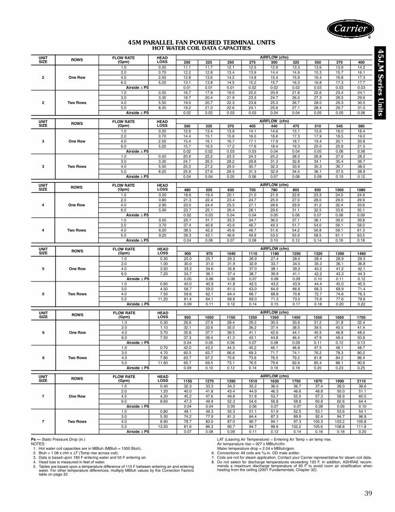
39
45
J,M S
eries Units
45M PARALLEL FAN POWERED TERMINAL UNITSHOT WATER COIL DATA CAPACITIES
Ps — Static Pressure Drop (in.)NOTES:
1. Hot water coil capacities are in MBtuh (MBtuh = 1000 Btuh).2. Btuh = 1.08 x cfm x ΔT (Temp rise across coil).3. Data is based upon 180 F entering water and 55 F entering air.4. Head loss is measured in feet of water.5. Tables are based upon a temperature difference of 115 F between entering air and entering
water. For other temperature differences, multiply MBtuh values by the Correction Factorstable on page 32.
LAT (Leaving Air Temperature) = Entering Air Temp + air temp rise.Air temperature rise = 927 x MBtuh/cfm.Water temperature drop = 2.04 x MBtuh/gpm.
6. Connections: All coils are 5/8-in. OD male solder.7. Coils are not for steam application. Contact your Carrier representative for steam coil data.8. Do not select for discharge temperatures exceeding 120 F. In addition, ASHRAE recom-
mends a maximum discharge temperature of 95 F to avoid room air stratification whenheating from the ceiling (2001 Fundamentals, Chapter 32).
UNITSIZE ROWS FLOW RATE
(Gpm)HEADLOSS
AIRFLOW (cfm)200 225 250 275 300 325 350 375 400
2 One Row
1.0 0.20 11.1 11.7 12.1 12.5 12.9 13.3 13.6 13.9 14.22.0 0.70 12.2 12.8 13.4 13.9 14.4 14.9 15.3 15.7 16.14.0 2.50 12.8 13.6 14.2 14.8 15.4 15.9 16.4 16.8 17.36.0 5.20 13.1 13.8 14.5 15.2 15.7 16.3 16.8 17.3 17.7
Airside Δ PS 0.01 0.01 0.01 0.02 0.02 0.02 0.03 0.03 0.03
2 Two Rows
1.0 0.50 16.7 17.9 19.0 20.0 20.9 21.8 22.6 23.4 24.13.0 3.30 18.7 20.4 21.9 23.3 24.7 26.0 27.3 28.5 29.64.0 5.50 19.0 20.7 22.3 23.8 25.3 26.7 28.0 29.3 30.55.0 8.20 19.2 21.0 22.6 24.1 25.6 27.1 28.4 29.7 31.0
Airside Δ PS 0.02 0.02 0.03 0.03 0.04 0.04 0.05 0.05 0.06
UNITSIZE ROWS FLOW RATE
(Gpm)HEADLOSS
AIRFLOW (cfm)300 335 370 405 440 475 510 545 580
3 One Row
1.0 0.20 12.9 13.4 13.9 14.1 14.6 15.1 15.6 16.0 16.42.0 0.70 14.4 15.1 15.6 16.0 16.6 17.3 17.9 18.5 19.04.0 2.50 15.4 16.1 16.7 17.1 17.9 18.7 19.4 20.1 20.86.0 5.20 15.7 16.5 17.2 17.6 18.4 19.3 20.0 20.8 21.5
Airside Δ PS 0.02 0.02 0.03 0.03 0.04 0.04 0.05 0.06 0.06
3 Two Rows
1.0 0.50 20.9 22.2 23.3 24.3 25.2 28.0 26.8 27.6 28.23.0 3.30 24.7 26.5 28.2 29.8 31.3 32.8 34.1 35.4 36.74.0 5.50 25.3 27.2 29.0 30.7 32.3 33.9 35.3 36.7 38.05.0 8.20 25.9 27.6 29.5 31.3 32.9 34.5 36.1 37.5 38.9
Airside Δ PS 0.04 0.04 0.05 0.06 0.07 0.08 0.09 0.10 0.12
UNITSIZE ROWS FLOW RATE
(Gpm)HEADLOSS
AIRFLOW (cfm)480 555 630 705 780 855 930 1005 1080
4 One Row
1.0 0.20 18.6 19.4 20.1 21.0 21.9 22.6 23.3 24.0 24.62.0 0.80 21.3 22.4 23.4 24.7 25.9 27.0 28.0 29.0 29.94.0 2.90 23.0 24.4 25.5 27.1 28.6 29.9 31.2 32.4 33.66.0 5.90 23.7 25.1 26.4 28.1 29.6 31.1 32.5 33.8 35.1
Airside Δ PS 0.02 0.03 0.04 0.04 0.05 0.06 0.07 0.08 0.09
4 Two Rows
1.0 0.50 29.7 31.7 33.3 34.7 36.0 37.1 38.1 39.0 39.83.0 3.70 37.4 40.8 43.9 46.7 49.3 51.7 54.0 56.1 58.04.0 6.20 38.5 42.2 45.6 46.7 51.6 54.2 56.8 59.1 61.35.0 9.20 39.3 43.1 46.6 49.9 53.0 55.9 58.5 61.1 63.5
Airside Δ PS 0.04 0.06 0.07 0.08 0.10 0.12 0.14 0.16 0.18
UNITSIZE ROWS FLOW RATE
(Gpm)HEADLOSS
AIRFLOW (cfm)900 970 1040 1110 1180 1250 1320 1390 1460
5 One Row
1.0 0.30 25.0 25.7 26.3 26.9 27.4 28.0 28.4 28.9 29.32.0 1.00 30.0 31.0 31.9 32.9 33.7 34.5 35.3 36.1 36.84.0 3.50 33.3 34.6 35.8 37.0 38.1 39.2 40.2 41.2 42.16.0 7.20 34.7 36.1 37.4 38.7 39.9 41.1 42.2 43.3 44.3
Airside Δ PS 0.05 0.06 0.06 0.07 0.08 0.09 0.10 0.11 0.12
5 Two Rows
1.0 0.60 40.0 40.9 41.8 42.5 43.2 43.9 44.4 45.0 45.53.0 4.50 56.7 59.0 61.0 63.0 64.9 66.6 68.3 69.9 71.44.0 7.50 59.6 62.1 64.4 66.7 68.8 70.8 72.7 74.6 76.35.0 11.20 61.4 64.1 66.6 69.0 71.3 73.5 75.6 77.6 79.6
Airside Δ PS 0.09 0.11 0.12 0.14 0.15 0.17 0.18 0.20 0.22
UNITSIZE ROWS FLOW RATE
(Gpm)HEADLOSS
AIRFLOW (cfm)950 1050 1150 1250 1350 1450 1550 1650 1750
6 One Row
1.0 0.30 26.6 27.6 28.4 29.2 30.0 30.6 31.2 31.8 32.42.0 1.10 32.1 33.6 35.0 36.2 37.4 38.5 39.5 40.5 41.44.0 3.70 35.8 37.7 39.5 41.1 42.6 44.1 45.5 46.8 48.06.0 7.50 37.3 39.4 41.3 43.1 44.8 46.4 47.9 49.4 50.8
Airside Δ PS 0.04 0.05 0.06 0.07 0.08 0.09 0.11 0.12 0.13
6 Two Rows
1.0 0.70 42.0 43.2 44.3 45.2 46.1 46.8 47.5 48.1 48.73.0 4.70 60.5 63.7 66.6 69.3 71.7 74.1 76.2 78.3 80.24.0 7.80 63.7 67.2 70.6 73.6 76.5 79.2 81.8 84.2 86.45.0 11.60 65.7 69.5 73.1 76.5 79.6 82.6 85.4 88.1 90.6
Airside Δ PS 0.09 0.10 0.12 0.14 0.16 0.18 0.20 0.23 0.25
UNITSIZE ROWS FLOW RATE
(Gpm)HEADLOSS
AIRFLOW (cfm)1150 1270 1390 1510 1630 1750 1870 1990 2110
7 One Row
1.0 0.40 32.3 33.3 34.3 35.2 36.0 36.7 37.4 38.0 38.62.0 1.20 40.0 41.8 43.4 44.9 46.3 46.6 48.8 50.0 51.14.0 4.20 45.2 47.6 49.8 51.8 53.7 55.5 57.3 58.9 60.56.0 8.60 47.3 49.9 52.3 54.6 56.8 58.8 60.8 62.6 64.4
Airside Δ PS 0.04 0.04 0.05 0.06 0.07 0.07 0.08 0.09 0.10
7 Two Rows
1.0 0.80 48.1 49.3 50.3 51.1 51.9 52.5 53.1 53.6 54.13.0 5.30 74.2 77.9 81.3 84.4 87.3 89.9 92.4 94.7 96.94.0 8.90 78.7 83.0 87.0 90.7 94.1 97.3 100.3 103.2 105.85.0 13.20 81.6 86.3 90.7 94.7 98.6 102.2 105.6 108.8 111.8
Airside Δ PS 0.07 0.08 0.09 0.11 0.12 0.14 0.16 0.18 0.20

40
45J,
M S
erie
s U
nits
45J SERIES FAN POWERED TERMINAL UNIT WITH ELECTRIC HEAT — kW RANGES
LEGEND
NOTES: 1. Three-stage heaters are not available with analog controls.2. Pneumatic and digital controlled terminals are available with up to
3 stages of heat. Analog controlled terminals are available with1 or 2 stages of heat only.
3. Heaters require a minimum of 0.03 in. wg downstream staticpressure to ensure proper operation.
45M PARALLEL FAN POWERED TERMINAL UNIT WITH ELECTRIC HEAT — kW RANGES
4. kW/Voltage ratings are sized not to exceed 48 amps so NEC coderequirement for circuit fusing is not necessary.
Electric heat selection — Specify electric duct heatersusing voltage, kW and number of steps.Select heater so that power (kW) matches available electricheat options. Tables show maximum, minimum andavailable kW’s within those ranges. Rounding to thenearest whole number has negligible impact on dischargetemperature. If the fan is selected for less than maximumspeed, then the maximum operating kW would be lowerthan the maximum kW shown in the table. Calculate kWbased on the available fan cfm. A minimum of 70 cfm isrequired per kW.Total fan cfm/70 cfm = max allowable kWThe Total kW required for the unit is based on the sumof both (A) room Btuh load and (B) the Btuh required toraise the entering air temperature to the desired room airtemperature. Total kW = room Btuh + ΔBtuh
where Δt = desired room temp. – air entering electricheater (typically 70 F)
Determine what the desired discharge air temp will be. Donot select for discharge air temperatures exceeding 120 F.In addition note that ASHRAE recommends a maximumdischarge temperature of 90 F to avoid room air tempera-ture stratification when heating from the ceiling (2001Fundamentals, Chapter 32).
LAT = Discharge air temp EAT = Air temp to heater
The desired heating airflow for the space can be verifiedby the following:
ELECTRIC HEAT kW OPTIONS
UNITSIZE
MAXIMUM kW120 V 208 V 240 V 277 V 208/240 V 480 V
Single Phase 3 Phase2 5.0 5.0 5.0 5.0 5.0 5.03 5.0 5.0 5.0 5.0 5.0 5.04 4.5 9.0 9.0 10.0 12.0 13.05 4.5 9.0 9.0 12.0 14.0 19.06 4.5 8.5 8.5 12.0 13.0 23.07 N/A 6.5 7.5 10.0 11.0 25.0
STAGESMINIMUM kW
120 V 208 V 240 V 277 V 208/240 V 480 VSingle Phase 3 Phase
1 .5 .5 .5 .5 1.5 1.52 1.0 1.0 1.0 1.0 1.5 1.53 1.5 1.5 1.5 1.5 1.5 1.5
kW — Heating Capacity (kilowatts)
UNITSIZE
MAXIMUM kW120 V 208 V 240 V 277 V 208/240 V 480 V
Single Phase 3 Phase2 4.0 4.0 4.0 4.0 4.0 4.03 5.5 6.0 6.0 6.0 6.0 6.04 5.0 6.0 6.0 6.0 6.0 6.05 4.5 9.0 9.0 12.0 12.0 12.06 4.5 8.0 9.0 12.0 14.0 14.07 4.5 8.5 8.5 12.0 15.0 18.0
STAGESMINIMUM kW
120 V 208 V 240 V 277 V 208/240 V 480 VSingle Phase 3 Phase
1 .5 .5 .5 .5 1.5 1.52 1.0 1.0 1.0 1.0 1.5 1.53 1.5 1.5 1.5 1.5 1.5 1.5
Single Phase — Amperes = Watts (kW x 1000)Line Voltage
Three Phase — Amperes = Watts (kW x 1000)Line Voltage x 1.73
room Btuh kW = room Btuh3413
Δ Btuh kW = cfm x Δt3160
Δt = (LAT – EAT ) = kW x 3160cfm
cfm = kW x 3160Δt
UNIT AVAILABLE kW
45J
0.5, 1.0, 1.5, 2.0, 2.5, 3.0, 3.5, 4.0, 4.5, 5.0, 5.5, 6.0, 6.5, 7.0, 7.5, 8.0, 8.5, 9.0, 9.5, 10.0, 11.0, 12.0, 13.0, 14.0, 15.0, 16.0, 17.0, 18.0, 19.0, 20.0, 22.0, 23.0, 24.0, 25.0
45M
0.5, 1.0, 1.5, 2.0, 2.5, 3.0, 3.5, 4.0, 4.5, 5.0, 5.5, 6.0, 6.5, 7.0, 7.5, 8.0, 8.5, 9.0, 9.5, 10.0, 11.0, 12.0, 13.0, 14.0, 15.0, 16.0, 17.0, 18.0
Electrical data

41
45K
,N S
eries Units
45 K – Quiet Series Flow FanPowered Unit (Constant Volume)
Sensor Type1 – Linear Averaging (standard)
Liner0 – Standard (½ in. thick)1 – Fiberglass (1 in. dual density)2 – Steriliner3 – No Liner4 – Sterilwall with ½ in. Dual Density Liner5 – Cellular6 – ½ in. Foil Encapsulated Liner8 – Sterilwall with 1 in. Dual Density Liner9 – 1 in. Foil Encapsulated LinerA – Perforated Wall with ½ in. Dual Density LinerB – Perforated Wall with 1 in. Dual Density LinerC – Perforated Wall with ½ in. Foil Encapsulated LinerD – Perforated Wall with 1 in. Foil Encapsulated LinerE – Steriliner Perforated Wall
Controls A – AnalogP – PneumaticC – PIC CCN ControlsN – No Controls
Unit CasingLEFT RIGHT DESCRIPTION
1L 1R 20 Gage Steel
Inlet Size06 – 6 in.08 – 8 in.10 – 10 in.12 – 12 in.14 – 14 in.16 – 16 in.
Control Codes* D00X – No Controls13XX – Pneumatic22XX – Analog44XX – PIC CCN Controls
Unit Size2 53 64 7
Voltage1 – 120-1-602 – 208/240-1-603 – 277-1-606 – 277-1-60 with ECM Motor†
C
45N – Quiet Parallel Flow FanPowered Unit (Variable Volume)
Sensor Type 1 – Linear Averaging (standard)
Liner 0 – Standard (½ in. thick)1 – Fiberglass (1 in. dual density)2 – Steriliner3 – No Liner4 – Sterilwall with ½ in. Dual Density Liner5 – Cellular6 – ½ in. Foil Encapsulated Liner8 – Sterilwall with 1 in. Dual Density Liner9 – 1 in. Foil Encapsulated LinerA – Perforated Wall with ½ in. Dual Density LinerB – Perforated Wall with 1 in. Dual Density LinerC – Perforated Wall with ½ in. Foil Encapsulated LinerD – Perforated Wall with 1 in. Foil Encapsulated LinerE – Steriliner Perforated Wall
Controls A – AnalogP – PneumaticC – PIC CCN ControlsV – 3V™ VVT® ControlsN – No Controls
Unit Casing LEFT RIGHT DESCRIPTION
1L 1R 20 Gage Steel
Inlet Size 06 – 6 in.08 – 8 in.10 – 10 in.12 – 12 in.14 – 14 in.16 – 16 in.
Control Codes* D00X – No Controls14XX – Pneumatic23XX – Analog47XX – PIC CCN Controls88XX – 3V VVT Controls
Unit Size 2 5 3 6 4 7
Voltage 1 – 120-1-602 – 208/240-1-603 – 277-1-606 – 277-1-60 with ECM Motor**
LEGENDCCN — Carrier Comfort Network®ECM — Electronically Commutated MotorPIC — Product Integrated ControlsVVT — Variable Volume and Temperature
a45-491
a45-492
45N QUIET PARALLEL FAN POWERED TERMINALS
45K QUIET SERIES FAN POWERED TERMINALS
*See pages 6 to 8 for complete control code number list.†Sizes 3, 6, and 7 only.**Sizes 4 and 7 only.
Model number nomenclature
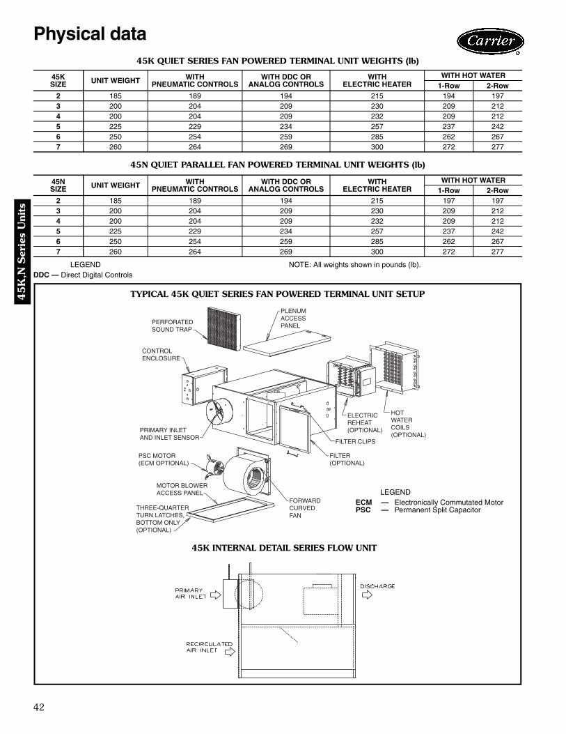
42
45
K,N
Ser
ies
Uni
ts
45K QUIET SERIES FAN POWERED TERMINAL UNIT WEIGHTS (lb)
45N QUIET PARALLEL FAN POWERED TERMINAL UNIT WEIGHTS (lb)
LEGENDDDC — Direct Digital Controls
NOTE: All weights shown in pounds (lb).
45KSIZE UNIT WEIGHT WITH
PNEUMATIC CONTROLSWITH DDC OR
ANALOG CONTROLSWITH
ELECTRIC HEATERWITH HOT WATER
1-Row 2-Row2 185 189 194 215 194 1973 200 204 209 230 209 2124 200 204 209 232 209 2125 225 229 234 257 237 2426 250 254 259 285 262 2677 260 264 269 300 272 277
45NSIZE UNIT WEIGHT WITH
PNEUMATIC CONTROLSWITH DDC OR
ANALOG CONTROLSWITH
ELECTRIC HEATERWITH HOT WATER
1-Row 2-Row2 185 189 194 215 197 1973 200 204 209 230 209 2124 200 204 209 232 209 2125 225 229 234 257 237 2426 250 254 259 285 262 2677 260 264 269 300 272 277
PERFORATEDSOUND TRAP
CONTROLENCLOSURE
PRIMARY INLETAND INLET SENSOR
PSC MOTOR(ECM OPTIONAL)
MOTOR BLOWERACCESS PANEL
FORWARDCURVEDFAN
FILTER(OPTIONAL)
ELECTRICREHEAT(OPTIONAL)
HOTWATERCOILS(OPTIONAL)
PLENUMACCESSPANEL
THREE-QUARTERTURN LATCHES, BOTTOM ONLY(OPTIONAL)
FILTER CLIPS
TYPICAL 45K QUIET SERIES FAN POWERED TERMINAL UNIT SETUP
45K INTERNAL DETAIL SERIES FLOW UNIT
LEGENDECM — Electronically Commutated MotorPSC — Permanent Split Capacitor
Physical data
a45-493

43
45K
,N S
eries Units
45K,N OPTIONAL FILTER SIZES AND PART NUMBERS
UNIT UNIT SIZE FILTER SIZE FILTER P/N FILTER KIT P/N
45K,N2,3,4 17X17X1 102649-1717 35033417175,6,7 22X19X1 102649-2219 3503342219
CONTROLENCLOSURE
PRIMARYINLET SENSOR
FORWARDCURVEDFAN
MOTOR BLOWERACCESS PANEL
PSC MOTOR(ECM MOTOR OPTIONAL)
FILTER (OPTIONAL)
FILTER CLIPS
HOT WATER COIL(OPTIONAL WITH PLENUM MOUNTING)
ELECTRICREHEAT(OPTIONAL)
INLET ACCESSPANEL
BACKDRAFT DAMPER
THREE-QUARTERTURN FASTENERS, BOTTOM ONLY(OPTIONAL)
TYPICAL 45N QUIET PARALLEL FAN POWERED TERMINAL UNIT SETUP
45N INTERNAL DETAIL PARALLEL FLOW UNIT
a45-494
LEGENDECM — Electronically Commutated MotorPSC — Permanent Split Capacitor

44
45
K,N
Ser
ies
Uni
ts
LEGENDDD — Linear Averaging Sensor/Inlet (Inlet Sizes: 6-10 DD = 37/8-in.; 12-16 DD = 57/8-in.)
NOTE: Dimensions are given in inches.
45K QUIET SERIES FAN POWERED TERMINAL UNITS
INLET VIEW DISCHARGE VIEWPLAN VIEW — LEFT HAND UNIT SHOWNRIGHT HAND AVAILABLE(CONTROLS NOT SHOWN)
TINUEZIS
TELNIEZIS
.IRPMFC
NAFMFC PH L W H
RIA.CRICERD
EGRAHCSIDX Y Z
A B F G
2 68
515035
035035
01/101/1
39 1/2 8/1638/163
61/18161/181
8/1518/151
5151
8/758/75
1111
4141
99
66
8/138/13
36801
5150290011
001100110011
4/14/14/1
8/1638/1638/163
61/18161/18161/181
8/1518/1518/151
515151
8/758/778/79
111111
414141
999
667
8/138/138/13
480121
02900310031
003100310031
4/14/14/1
717171
8/778/798/711
111111
414141
678
5012141
034100910091
009100910091
2/12/12/1
8/1248/1248/124
8/1648/1648/164
61/10261/10261/102
8/1028/1028/102
717171
8/798/7118/731
515151
717171
010101
7801
2/152/152/15
601214161
0341060200620062
0062006200620062
4/34/34/34/3
8/1248/1248/1248/124
8/1648/1648/1648/164
61/10261/10261/10261/102
8/1028/1028/1028/102
71717171
8/798/7118/7318/751
51515151
71717171
01010101
7801
4/101
2/152/152/152/15
701214161
0341060200820663
0003000300030003
1111
8/1248/1248/1248/124
8/1648/1648/1648/164
61/10261/10261/10261/102
8/1028/1028/1028/102
71717171
8/798/7118/7318/751
51515151
71717171
01010101
7801
4/101
2/152/152/152/15
39 1/239 1/2
39 1/239 1/2
39 1/24/121 0011 0011 8/163 61/181 8/151 51 8/79 11 41 9 7 8/138/1248/1248/124
8/1648/1648/164
61/10261/10261/102
8/1028/1028/102
010101
2/152/152/15
Dimensions

45
45K
,N S
eries Units
HEATERTERMINATIONENCLOSURE(ALLOW 36” CLEARANCE FORELECTRICAL ENCLOSURES)
11 7/8”
HANGER BRACKETS-(4 PLS)
LEGENDDD — Linear Averaging Sensor/Inlet (Inlet Sizes: 6-10 DD = 37/8-in.; 12-16 DD = 57/8-in.)
NOTE: Dimensions are given in inches.
45K QUIET SERIES FAN POWERED TERMINAL UNITSWITH ELECTRIC HEAT AND ELECTRONIC CONTROLS
INLET VIEW DISCHARGE VIEWPLAN VIEW — LEFT HAND UNIT SHOWNRIGHT HAND AVAILABLE
(CONTROLS NOT SHOWN)
TINUEZIS
TELNIEZIS
.IRPMFC
NAFMFC PH L W H
RIA.CRICERD
EGRAHCSIDX Y
A B F G
2 68
515035
035035
01/101/1
39 1/2 8/1638/163
61/18161/181
8/1518/151
5151
8/758/75
1 1/211 1/21
4 1/214 1/21
99
66
8/728/72
36801
5150290011
001100110011
4/14/14/1
8/1638/1638/163
61/18161/18161/181
8/1518/1518/151
515151
8/758/778/79
1 1/211 1/211 1/21
4 1/214 1/214 1/21
999
667
8/728/728/72
480121
02900310031
003100310031
4/14/14/1
717171
8/778/798/711
1 1/211 1/211 1/21
4 1/214 1/214 1/21
678
5012141
034100910091
009100910091
2/12/12/1
8/1248/1248/124
8/1648/1648/164
61/10261/10261/102
8/1028/1028/102
717171
8/798/7118/731
515151
717171
010101
7801
2/152/152/15
601214161
0341060200620062
0062006200620062
4/34/34/34/3
8/1248/1248/1248/124
8/1648/1648/1648/164
61/10261/10261/10261/102
8/1028/1028/1028/102
71717171
8/798/7118/7318/751
51515151
71717171
01010101
7801
4/101
2/152/152/152/15
701214161
0341060200820663
0003000300030003
1111
8/1248/1248/1248/124
8/1648/1648/1648/164
61/10261/10261/10261/102
8/1028/1028/1028/102
71717171
8/798/7118/7318/751
51515151
71717171
01010101
7801
4/101
2/152/152/152/15
39 1/239 1/2
39 1/239 1/2
39 1/24/121 0011 0011 8/163 61/181 8/151 51 8/79 1 1/21 4 1/21 9 7 8/728/1248/1248/124
8/1648/1648/164
61/10261/10261/102
8/1028/1028/102
JZ
33333333344444444444
010101
2/152/152/15
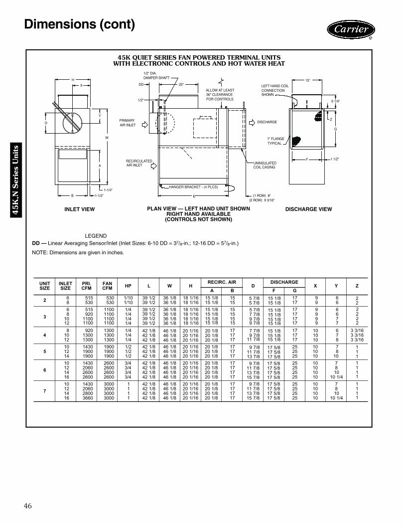
46
45
K,N
Ser
ies
Uni
ts
HANGER BRACKET - (4 PLCS)
L
1-1/4"
B 1-1/2"
H
D
RECIRCULATEDAIR INLET
PRIMARYAIR INLET
A
Y
W
X
1/2" DIA.DAMPER SHAFT
1/2"
DD 20"
(1 ROW) 8"(2 ROW) 9 3/16"
UNINSULATEDCOIL CASING
1" FLANGETYPICAL
DISCHARGE
F
LEFT HAND COILCONNECTIONSHOWN
15"
1 1/2"
Z
G
6 1/4"
ALLOW AT LEAST36" CLEARANCEFOR CONTROLS
LEGENDDD — Linear Averaging Sensor/Inlet (Inlet Sizes: 6-10 DD = 37/8-in.; 12-16 DD = 57/8-in.)
NOTE: Dimensions are given in inches.
45K QUIET SERIES FAN POWERED TERMINAL UNITSWITH ELECTRONIC CONTROLS AND HOT WATER HEAT
INLET VIEW DISCHARGE VIEWPLAN VIEW — LEFT HAND UNIT SHOWNRIGHT HAND AVAILABLE(CONTROLS NOT SHOWN)
TINUEZIS
TELNIEZIS
.IRPMFC
NAFMFC PH L W H
RIA.CRICERD
EGRAHCSIDX Y Z
A B F G
2 68
515035
035035
01/101/1
39 1/2 8/1638/163
61/18161/181
8/1518/151
5151
7171
99
66
36801
5150290011
001100110011
4/14/14/1
8/1638/1638/163
61/18161/18161/181
8/1518/1518/151
515151
717171
999
667
480121
02900310031
003100310031
4/14/14/1
717171
717171
678
16/3316/3316/33
5012141
034100910091
009100910091
2/12/12/1
8/1248/1248/124
8/1648/1648/164
61/10261/10261/102
8/1028/1028/102
717171
525252
010101
7801
601214161
0341060200620062
0062006200620062
4/34/34/34/3
8/1248/1248/1248/124
8/1648/1648/1648/164
61/10261/10261/10261/102
8/1028/1028/1028/102
71717171
52525252
01010101
7801
4/101
701214161
0341060200820663
0003000300030003
1111
8/1248/1248/1248/124
8/1648/1648/1648/164
61/10261/10261/10261/102
8/1028/1028/1028/102
71717171
8/798/7118/7318/751
52525252
01010101
7801
4/101
39 1/239 1/2
39 1/239 1/2
39 1/24/121 0011 0011 8/163 61/181 8/151 51 71 9 78/1248/1248/124
8/1648/1648/164
61/10261/10261/102
8/1028/1028/102
8/758/758/758/778/798/79
8/778/798/711
8/798/7118/7318/751
8/798/7118/731
010101
222222
11111111
111
8/578/5718/5718/571
1
8/578/5718/5718/571
1
8/578/5718/571
1
8/1518/1518/151
8/1518/1518/1518/151
8/1518/151
Dimensions (cont)
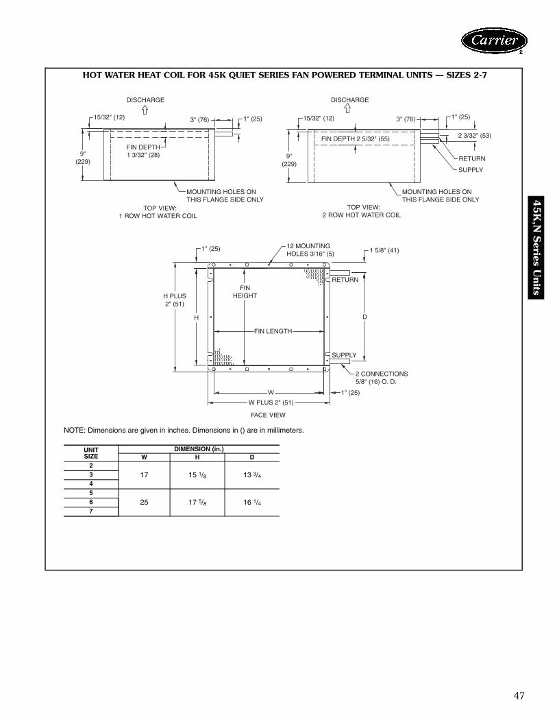
47
45K
,N S
eries Units
9"(229)
15/32" (12)
DISCHARGE
3" (76)
FIN DEPTH1 3/32" (28)
1" (25)
MOUNTING HOLES ONTHIS FLANGE SIDE ONLY
9"(229)
15/32" (12)
DISCHARGE
3" (76) 1" (25)
2 3/32" (53)
RETURN
SUPPLY
MOUNTING HOLES ONTHIS FLANGE SIDE ONLY
1 5/8" (41)
RETURN
D
SUPPLY
2 CONNECTIONS5/8" (16) O. D.
1" (25)W
W PLUS 2" (51)
FIN LENGTH
FINHEIGHT
H
H PLUS2" (51)
1" (25) 12 MOUNTINGHOLES 3/16" (5)
TOP VIEW:1 ROW HOT WATER COIL
TOP VIEW:2 ROW HOT WATER COIL
FACE VIEW
FIN DEPTH 2 5/32" (55)
HOT WATER HEAT COIL FOR 45K QUIET SERIES FAN POWERED TERMINAL UNITS — SIZES 2-7
NOTE: Dimensions are given in inches. Dimensions in () are in millimeters.
UNITSIZE
DIMENSION (in.)W H D
2
17 15 1/8 13 3/4345
25 17 5/8 16 1/467
a45-495

48
45
K,N
Ser
ies
Uni
ts
BUTTONACCESS
LEGENDDD — Linear Averaging Sensor/Inlet (Inlet Sizes: 6-10 DD = 37/8-in.; 12-16 DD = 57/8-in.)
NOTE: Dimensions are given in inches.
45N QUIET PARALLEL FAN POWERED TERMINAL UNITS
INLET VIEW DISCHARGE VIEWPLAN VIEW — LEFT HAND UNIT SHOWNRIGHT HAND AVAILABLE
(CONTROLS NOT SHOWN)
TINUEZIS
TELNIEZIS
.IRPMFC
NAFMFC PH L W H
RIA.CRICERD
EGRAHCSIDX Y Z
A B F G
2 68
515035
035035
01/101/1
39 1/2 8/1638/163
61/18161/181
8/1518/151
5151
8/758/75
1111
4141
99
66
8/138/13
36801
5150290011
001100110011
4/14/14/1
8/1638/1638/163
61/18161/18161/181
8/1518/1518/151
515151
8/758/778/79
111111
414141
999
667
8/138/138/13
480121
02900310031
003100310031
4/14/14/1
717171
8/778/798/711
111111
414141
678
5012141
034100910091
009100910091
2/12/12/1
8/1248/1248/124
8/1648/1648/164
61/10261/10261/102
8/1028/1028/102
717171
8/798/7118/731
515151
717171
010101
7801
2/152/152/15
601214161
0341060200620062
0062006200620062
4/34/34/34/3
8/1248/1248/1248/124
8/1648/1648/1648/164
61/10261/10261/10261/102
8/1028/1028/1028/102
71717171
8/798/7118/7318/751
51515151
71717171
01010101
7801
4/101
2/152/152/152/15
701214161
0341060200820663
0003000300030003
1111
8/1248/1248/1248/124
8/1648/1648/1648/164
61/10261/10261/10261/102
8/1028/1028/1028/102
71717171
8/798/7118/7318/751
51515151
71717171
01010101
7801
4/101
2/152/152/152/15
39 1/239 1/2
39 1/239 1/2
39 1/24/121 0011 0011 8/163 61/181 8/151 51 8/79 11 41 9 7 8/138/1248/1248/124
8/1648/1648/164
61/10261/10261/102
8/1028/1028/102
010101
2/152/152/15
Dimensions (cont)

49
45K
,N S
eries Units
HANGER BRACKETS-(4 PLS)
HEATER TERMINATION ENCLOSURE
LEGENDDD — Linear Averaging Sensor/Inlet (Inlet Sizes: 6-10 DD = 37/8-in.; 12-16 DD = 57/8-in.)
NOTE: Dimensions are given in inches.
45N QUIET PARALLEL FAN POWERED TERMINAL UNITSWITH ELECTRIC HEAT AND ELECTRONIC CONTROLS
INLET VIEW DISCHARGE VIEWPLAN VIEW — LEFT HAND UNIT SHOWNRIGHT HAND AVAILABLE
(CONTROLS NOT SHOWN)
TINUEZIS
TELNIEZIS
.IRPMFC
NAFMFC PH L W H
RIA.CRICERD
EGRAHCSIDX Y
A B F G
2 68
515035
035035
01/101/1
39 1/2 8/1638/163
61/18161/181
8/1518/151
5151
8/758/75
1 1/211 1/21
4 1/214 1/21
99
66
8/728/72
36801
5150290011
001100110011
4/14/14/1
8/1638/1638/163
61/18161/18161/181
8/1518/1518/151
515151
8/758/778/79
1 1/211 1/211 1/21
4 1/214 1/214 1/21
999
667
8/728/728/72
480121
02900310031
003100310031
4/14/14/1
717171
8/778/798/711
1 1/211 1/211 1/21
4 1/214 1/214 1/21
678
5012141
034100910091
009100910091
2/12/12/1
8/1248/1248/124
8/1648/1648/164
61/10261/10261/102
8/1028/1028/102
717171
8/798/7118/731
515151
717171
010101
7801
2/152/152/15
601214161
0341060200620062
0062006200620062
4/34/34/34/3
8/1248/1248/1248/124
8/1648/1648/1648/164
61/10261/10261/10261/102
8/1028/1028/1028/102
71717171
8/798/7118/7318/751
51515151
71717171
01010101
7801
4/101
2/152/152/152/15
701214161
0341060200820663
0003000300030003
1111
8/1248/1248/1248/124
8/1648/1648/1648/164
61/10261/10261/10261/102
8/1028/1028/1028/102
71717171
8/798/7118/7318/751
51515151
71717171
01010101
7801
4/101
2/152/152/152/15
39 1/239 1/2
39 1/239 1/2
39 1/24/121 0011 0011 8/163 61/181 8/151 51 8/79 1 1/21 4 1/21 9 7 8/728/1248/1248/124
8/1648/1648/164
61/10261/10261/102
8/1028/1028/102
JZ
33333333344444444444
010101
2/152/152/15

50
45
K,N
Ser
ies
Uni
ts
LEGENDDD — Linear Averaging Sensor/Inlet (Inlet Sizes: 6-10 DD = 37/8-in.; 12-16 DD = 57/8-in.)
NOTE: Dimensions are given in inches.
45N QUIET PARALLEL FAN POWERED TERMINAL UNITS WITH ELECTRONIC CONTROLSAND HOT WATER HEAT ON UNIT DISCHARGE
INLET VIEW DISCHARGE VIEWPLAN VIEW — LEFT HAND UNIT SHOWN(COIL CONNECTIONS SHOWN ON LEFT SIDE,
BUT AVAILABLE ON EITHER HAND)
L
HANGER BRACKET - (4 PLCS)1-1/4"
B 1-1/2"
DPRIMARYAIR INLET
A
W
Y
H
X
1/2"
RECIRCULATEDAIR INLET
1/2" DIA.DAMPER SHAFT
DD 20"
Z(1 ROW) 8"
(2 ROW) 9 3/16"F 1 1/2"
LEFT HAND COILCONNECTIONSHOWN
UNINSULATEDCOIL CASING
DISCHARGE
ALLOW AT LEAST36" CLEARANCEFOR CONTROLENCLOSURE
6 1/4"
1" FLANGETYPICAL
11 7/8"
G
BOTTOMACCESS
TINUEZIS
TELNIEZIS
.IRPMFC
NAFMFC PH L W H
RIA.CRICERD
EGRAHCSIDX Y Z
A B F G
2 68
515035
035035
01/101/1
39 1/2 8/1638/163
61/18161/181
8/1518/151
5151
7171
99
66
36801
5150290011
001100110011
4/14/14/1
8/1638/1638/163
61/18161/18161/181
8/1518/1518/151
515151
717171
999
667
480121
02900310031
003100310031
4/14/14/1
717171
717171
678
16/3316/3316/33
5012141
034100910091
009100910091
2/12/12/1
8/1248/1248/124
8/1648/1648/164
61/10261/10261/102
8/1028/1028/102
717171
525252
010101
7801
601214161
0341060200620062
0062006200620062
4/34/34/34/3
8/1248/1248/1248/124
8/1648/1648/1648/164
61/10261/10261/10261/102
8/1028/1028/1028/102
71717171
52525252
01010101
7801
4/101
701214161
0341060200820663
0003000300030003
1111
8/1248/1248/1248/124
8/1648/1648/1648/164
61/10261/10261/10261/102
8/1028/1028/1028/102
71717171
8/798/7118/7318/751
52525252
01010101
7801
4/101
39 1/239 1/2
39 1/239 1/2
39 1/24/121 0011 0011 8/163 61/181 8/151 51 71 9 78/1248/1248/124
8/1648/1648/164
61/10261/10261/102
8/1028/1028/102
8/758/758/758/778/798/79
8/778/798/711
8/798/7118/7318/751
8/798/7118/731
010101
222222
11111111
111
8/578/5718/5718/571
1
8/578/5718/5718/571
1
8/578/5718/571
1
8/1518/1518/151
8/1518/1518/1518/151
8/1518/151
Dimensions (cont)
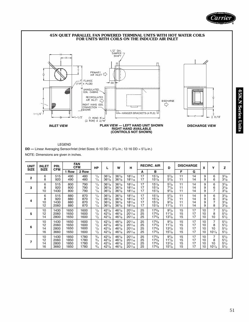
51
45K
,N S
eries Units
HANGER BRACKETS-(4 PLS)
45N QUIET PARALLEL FAN POWERED TERMINAL UNITS WITH HOT WATER COILSFOR UNITS WITH COILS ON THE INDUCED AIR INLET
LEGENDDD — Linear Averaging Sensor/Inlet (Inlet Sizes: 6-10 DD = 37/8-in.; 12-16 DD = 57/8-in.)
NOTE: Dimensions are given in inches.
UNITSIZE
INLETSIZE
PRI.CFM
FANCFM HP L W H
RECIRC. AIRD
DISCHARGEX Y Z
1 Row 2 Row A B F G
2 6 515 490 480 1/4 361/8 361/8 181/16 17 151/8 57/8 11 14 9 6 31/88 920 490 480 1/4 361/8 361/8 181/16 17 151/8 57/8 11 14 9 6 31/8
36 515 800 790 1/4 361/8 361/8 181/16 17 151/8 57/8 11 14 9 6 31/88 920 800 790 1/4 361/8 361/8 181/16 17 151/8 77/8 11 14 9 6 31/8
10 1430 800 790 1/4 361/8 361/8 181/16 17 151/8 97/8 11 14 9 7 31/8
4
6 515 880 870 1/4 361/8 361/8 181/16 17 151/8 57/8 11 14 9 6 31/88 920 880 870 1/4 361/8 361/8 181/16 17 151/8 77/8 11 14 9 6 31/8
10 1430 880 870 1/4 361/8 361/8 181/16 17 151/8 97/8 11 14 9 7 31/812 2060 880 870 1/4 361/8 361/8 181/16 17 151/8 117/8 11 14 9 8 31/8
510 1430 1650 1600 1/2 421/8 461/8 201/16 25 175/8 97/8 15 17 10 7 51/212 2060 1650 1600 1/2 421/8 461/8 201/16 25 175/8 117/8 15 17 10 8 51/214 2800 1650 1600 1/2 421/8 461/8 201/16 25 175/8 137/8 15 17 10 10 51/2
6
10 1430 1650 1600 1/2 421/8 461/8 201/16 25 175/8 97/8 15 17 10 7 51/212 2060 1650 1600 1/2 421/8 461/8 201/16 25 175/8 117/8 15 17 10 8 51/214 2800 1650 1600 1/2 421/8 461/8 201/16 25 175/8 137/8 15 17 10 10 51/216 3660 1650 1600 1/2 421/8 461/8 201/16 25 175/8 157/8 15 17 10 101/4 51/2
7
10 1430 1850 1780 3/4 421/8 461/8 201/16 25 175/8 97/8 15 17 10 7 51/212 2060 1850 1780 3/4 421/8 461/8 201/16 25 175/8 117/8 15 17 10 8 51/214 2800 1850 1780 3/4 421/8 461/8 201/16 25 175/8 137/8 15 17 10 10 51/216 3660 1850 1780 3/4 421/8 461/8 201/16 25 175/8 157/8 15 17 10 101/4 51/2
INLET VIEW DISCHARGE VIEWPLAN VIEW — LEFT HAND UNIT SHOWNRIGHT HAND AVAILABLE
(CONTROLS NOT SHOWN)

52
45
K,N
Ser
ies
Uni
ts
9"(229)
15/32" (12)
DISCHARGE
3" (76)
FIN DEPTH1 3/32" (28)
1" (25)
MOUNTING HOLES ONTHIS FLANGE SIDE ONLY
9"(229)
15/32" (12)
DISCHARGE
3" (76) 1" (25)
2 3/32" (53)
RETURN
SUPPLY
MOUNTING HOLES ONTHIS FLANGE SIDE ONLY
1 5/8" (41)
RETURN
D
SUPPLY
2 CONNECTIONS5/8" (16) O. D.
1" (25)W
W PLUS 2" (51)
FIN LENGTH
FINHEIGHT
H
H PLUS2" (51)
1" (25) 12 MOUNTINGHOLES 3/16" (5)
TOP VIEW:1 ROW HOT WATER COIL
TOP VIEW:2 ROW HOT WATER COIL
FACE VIEW
FIN DEPTH 2 5/32" (55)
HOT WATER HEAT COIL FOR 45N QUIET PARALLEL FAN POWERED TERMINAL UNITS — SIZES 2-7
NOTE: Dimensions are given in inches. Dimensions in () are in millimeters.
UNITSIZE
DIMENSION (in.)W H D
2
17 15 1/8 13 3/4345
25 17 5/8 16 1/467
a45-496
Dimensions (cont)

53
45K
,N S
eries Units
Unit Size 2
0
100
200
300
400
500
600
0.1 0.2 0.3 0.4 0.5 0.6External Static Pressure (in. wg)
m)
fc( yticap a
C na
F
Max Min 1 row HW 2 row HW
Unit Size 3
0
200
400
600
800
1000
1200
0.1 0.2 0.3 0.4 0.5 0.6External Static Pressure (in. wg)
m)
fc( yticapa
C na
F
Max Min 1 row HW 2 row HW
Unit Size 4
400
600
800
1000
1200
1400
1600
0.1 0.2 0.3 0.4 0.5 0.6External Static Pressure (in. wg)
mfc( yticapa
C na
F)
Max Min 1 row HW 2 row HW
Unit Size 5
200
600
1000
1400
1800
2200
0.1 0.2 0.3 0.4 0.5 0.6External Static Pressure (in. wg)
m)
fc(
ytic
ap
aC
na
F
Max Min 1 row HW 2 row HW
Unit Size 6
800
1200
1600
2000
2400
2800
0.1 0.2 0.3 0.4 0.5 0.6External Static Pressure (in. wg)
mfc( yticapa
C na
F)
Max Min 1 row HW 1 Row HW
Unit Size 7
1200
1600
2000
2400
2800
3200
0.1 0.2 0.3 0.4 0.5 0.6External Static Pressure (in. wg)
)mfc( ytica
paC
n aF
Max Min 1 row HW 2 row HW
45K QUIET SERIES FAN POWERED TERMINAL UNITS — FAN CURVES WITH PSC MOTOR OPTIONAIRFLOW VS. DOWNSTREAM STATIC PRESSURE
NOTES:1. Fan speed controller (SCR) is standard with each unit. Fan curve minimums indicate
maximum achievable flow reductions using speed control.2. Units must be selected to operate within the flow envelopes shown.3. Fan air discharge will be reduced approximately 5% when the unit is equipped with
factory-supplied electric heating coils.
LEGENDPSC — Permanent Split Capacitor
Performance data

54
45
K,N
Ser
ies
Uni
ts
45K QUIET SERIES FAN POWERED TERMINAL UNITS — FAN CURVES WITH ECM MOTOR OPTIONAIRFLOW VS. DOWNSTREAM STATIC PRESSURE
45K UNIT SIZE 4
0100200300400500600700800900
100011001200130014001500
0.1 0.2 0.3 0.4 0.5 0.6Static Pressure (in. wg)
Fan
Cap
acity
(cf
m)
45K UNIT SIZE 6
0
200
400
600
800
1000
1200
1400
1600
1800
2000
2200
0.1 0.2 0.3 0.4 0.5 0.6Static Pressure (in. wg)
Fan
Cap
acity
(cf
m)
45K UNIT SIZE 7
0
500
1000
1500
2000
2500
3000
0.1 0.2 0.3 0.4 0.5 0.6Static Pressure (in. wg)
Fan
Cap
acity
(cf
m)
Flow Range Outside Range
Flow Range Outside Range
Flow Range Outside Range
LEGENDECM — Electronically Commutated Motor
3
Performance data (cont)

55
45K
,N S
eries Units
45K quiet series fan powered terminal unit1. 45K maximum primary airflow (cfm) is based on
1.00 in. wg velocity pressure signal (VP), fromstandard Carrier linear averaging sensor.
2. Minimum recommended airflow (cfm) is based on0.03 in. wg differential pressure of the linear inletflow sensor, or 0 airflow, 0.03 in. wg is equal to 15%to 20% of the nominal flow rating of the terminal.Less than 15% to 20% may result in greater than±5% control of box flow.
3. Maximum induced airflow (cfm) is based on0.25 in. wg external downstream static pressure.
4. Minimum fan airflow (cfm) is based on maximumexternal (downstream) static pressure 0.6 in. wg.
5. Minimum primary airflow (cfm) listed is for all controlsexcept CCN controls, which is shown separately withlower available minimum cfm. Some DDC controlssupplied by others may have different limitations.
6. Motor amp draw = Power (w)/Voltage.
45K QUIET SERIES FAN POWERED TERMINAL UNITS (PSC MOTOR)
LEGEND *Max based on 0.1 in. wg downstream Ps for PSC motors. See Catalog for com-plete fan curves. Min based on 0.6 in. wg downstream Ps for PSC motors.
†For all controls except CCN controls. Some DDC controls supplied by others mayhave differing limitations.
NOTES:1. Data is based on tests conducted in accordance with ARI Standard 880-98.2. Minimum airflow for cooling or cooling with hot water heat is the minimum
flow rate controllable by the unit volume controller; shutoff or zero is alsoacceptable.
45K QUIET SERIES FAN POWERED TERMINAL UNITS (ECM MOTOR)
LEGEND
*Special order.†This value is based on signal of 0.03 in. wg differential pressure of the linear
averaging probe.
NOTES:1. Data is based on tests conducted in accordance with ARI Standard 880-98.2. Minimum airflow for cooling or cooling with hot water heat is the minimum
flow rate controllable by the unit volume controller; shutoff or zero is alsoacceptable.
UNITSIZE
INLETSIZE (in.)
PSC MOTORHP
MOTOR AMPS PRIMARY AIRFLOW FAN AIRFLOW*120 VFLA
208 VFLA
240 VFLA
277 VFLA
Max with PSC Min† Min CCN Max
PSCMinPSC
26 1/10 1.4 0.8 0.8 0.6
500 90 or 0 52 or 0530 50
8 530 170 or 0 93 or 0
36
1/4 4.3 2.4 2.4 1.8500 90 or 0 52 or 0
1150 1858 900 170 or 0 93 or 010 1150 250 or 0 145 or 0
4
6
1/4 4.3 2.4 2.4 1.8
500 90 or 0 52 or 0
1425 5008 900 170 or 0 93 or 0
10 1400 250 or 0 145 or 012 1425 360 or 0 210 or 0
510
1/2 8.3 4.4 4.4 3.51400 250 or 0 145 or 0
1900 80012 1900 360 or 0 210 or 014 1900 500 or 0 285 or 0
6
10
3/4 9.5 5.0 5.0 4.4
1400 250 or 0 145 or 0
2600 120012 2100 360 or 0 210 or 014 2500 500 or 0 285 or 016 2600 650 or 0 370 or 0
7
10
1 12.8 7.1 7.1 5.3
1400 250 or 0 145 or 0
3000 125012 2100 360 or 0 210 or 014 2500 500 or 0 285 or 016 3000 650 or 0 370 or 0
ARI — Air Conditioning and Refrigeration InstituteCCN — Carrier Comfort Network® ControlsDDC — Direct Digital ControlFLA — Full Load AmpsPSC — Permanent Split Capacitor MotorPs — Static Pressure
UNITSIZE
INLETSIZE (in.)
ECM MOTORHP
ECM MOTOR AMPS PRIMARY AIRFLOW FAN AIRFLOW120 V FLA* 240 V FLA* 277 V FLA Max with ECM Min† Min CCN Max ECM Min ECM
3
6
1/2 7.7 5.0 4.1
500 90 or 0 52 or 0
1030 2508 900 170 or 0 93 or 0
10 1400 250 or 0 145 or 012 1400 360 or 0 209 or 0
6
10
1 12.8 9.4 6.9
1400 250 or 0 145 or 0
2000 50012 2000 360 or 0 209 or 014 2000 500 or 0 284 or 016 2000 650 or 0 370 or 0
7
10 1400 250 or 0 145 or 0
2500 60012 2100 360 or 0 209 or 014 2500 500 or 0 284 or 016 2500 650 or 0 370 or 0
ARI — Air Conditioning and Refrigeration InstituteCCN — Carrier Comfort Network ControlsECM — Electronically Commutated MotorFLA — Full Load Amps

56
45
K,N
Ser
ies
Uni
ts
45K QUIET SERIES FAN POWERED TERMINAL UNITSHOT WATER COIL DATA
See Legend and Notes on page 20.
UNITSIZE ROWS
FLOW RATE (gpm)
HEADLOSS
AIRFLOW (cfm)
200 240 280 320 360 400 440 480 520
2 One Row
1.0 0.30 12.0 12.9 13.7 14.4 15.0 15.6 16.1 16.5 16.92.0 1.00 13.1 14.3 15.3 16.2 17.0 17.7 18.3 18.9 19.44.0 3.20 13.7 15.1 16.2 17.2 18.1 19.0 19.7 20.4 21.16.0 6.70 14.0 15.4 16.6 17.6 18.6 19.5 20.3 21.0 21.7Airside Δ PS 0.01 0.01 0.01 0.01 0.02 0.02 0.02 0.03 0.03
2 Two Rows
1.0 0.60 16.7 18.7 20.4 22.0 23.4 24.6 25.8 26.8 27.72.0 2.00 18.1 20.6 22.8 24.9 26.8 28.6 30.2 31.7 33.24.0 6.90 18.8 21.6 24.2 26.5 28.8 30.9 32.9 34.7 36.56.0 14.30 19.1 22.0 24.6 27.1 29.5 31.7 33.9 35.9 37.8Airside Δ PS 0.01 0.01 0.02 0.02 0.03 0.04 0.04 0.05 0.06
UNITSIZE ROWS
FLOW RATE (gpm)
HEADLOSS
AIRFLOW (cfm)
300 370 440 510 580 650 720 790 860
3 One Row
1.0 0.30 14.1 15.2 16.1 16.8 17.4 18.2 19.0 19.6 20.32.0 1.00 15.7 17.1 18.3 19.3 20.1 21.2 22.3 23.3 24.24.0 3.20 16.7 18.4 19.7 20.9 21.9 23.3 24.5 25.7 26.86.0 6.70 17.1 18.8 20.3 21.5 22.6 24.0 25.4 26.7 27.9Airside Δ PS 0.01 0.02 0.02 0.03 0.02 0.04 0.05 0.06 0.07
3 Two Rows
1.0 0.60 21.2 23.7 25.8 27.5 29.0 30.3 31.5 32.5 33.42.0 2.00 23.9 27.2 30.2 32.8 35.2 37.3 39.2 41.0 42.64.0 6.90 25.4 29.3 32.9 36.1 39.1 41.8 44.3 46.7 48.95.0 10.30 25.7 29.8 33.4 36.8 39.9 42.8 45.5 48.0 50.3Airside Δ PS 0.02 0.03 0.04 0.05 0.07 0.08 0.10 0.12 0.13
UNITSIZE ROWS
FLOW RATE (gpm)
HEADLOSS
AIRFLOW (cfm)
300 375 450 525 600 675 750 825 900
4 One Row
1.0 0.30 14.1 15.2 16.2 16.9 17.6 18.5 19.3 20.0 20.62.0 1.00 15.7 17.2 18.5 19.5 20.4 21.6 22.7 23.7 24.74.0 3.20 16.7 18.5 19.9 21.2 22.3 23.7 25.0 26.3 27.56.0 6.70 17.1 18.9 20.5 21.8 23.0 24.5 26.0 27.3 28.6Airside Δ PS 0.01 0.02 0.02 0.03 0.04 0.05 0.06 0.07 0.08
4 Two Rows
1.0 0.60 21.2 23.9 26.0 27.9 29.4 30.8 32.0 33.0 33.92.0 2.00 23.9 27.5 30.6 33.3 35.8 38.0 40.0 41.8 43.54.0 6.90 25.4 29.6 33.3 36.7 39.9 42.7 45.3 47.8 50.15.0 10.30 25.7 30.0 33.9 37.5 40.8 43.8 46.6 49.2 51.6Airside Δ PS 0.02 0.03 0.04 0.06 0.07 0.09 0.11 0.13 0.15
UNITSIZE ROWS
FLOW RATE (gpm)
HEADLOSS
AIRFLOW (cfm)
500 620 740 860 980 1100 1220 1340 1460
5 One Row
1.0 0.40 22.1 23.6 24.8 25.8 26.5 27.7 28.6 29.5 30.32.0 1.30 25.6 27.8 29.6 31.1 32.3 34.0 35.6 37.0 38.34.0 4.40 27.7 30.4 32.7 34.6 36.1 38.3 40.3 42.2 44.06.0 9.00 28.5 31.4 33.9 36.0 37.6 40.0 42.3 44.4 46.3Airside Δ PS 0.01 0.02 0.02 0.03 0.03 0.04 0.05 0.06 0.07
5 Two Rows
1.0 0.80 31.9 35.0 37.4 39.3 40.9 42.2 43.4 44.3 45.22.0 2.70 38.0 43.0 47.3 51.0 54.2 57.0 59.5 61.8 63.84.0 9.20 41.5 47.9 53.6 58.6 63.2 67.4 71.2 74.7 78.05.0 13.70 42.3 48.9 54.9 60.3 65.2 69.7 73.9 77.8 81.4Airside Δ PS 0.02 0.03 0.04 0.05 0.07 0.08 0.10 0.11 0.13
Performance data (cont)

57
45K
,N S
eries Units
45K QUIET SERIES FAN POWERED TERMINAL UNITS (cont)HOT WATER COIL DATA (cont)
LEGENDPS — Static Pressure Drop (in. wg)
NOTES:1. Hot water coil capacities are in MBtuh (MBtuh = 1000 Btuh).2. Btuh = 1.08 x cfm x ΔT (Temp rise across coil).3. Data is based upon 180 F entering water and 55 F entering air.4. Head Loss is in feet of water.
5. Tables are based upon a temperature difference of 125 F betweenentering air and entering water. For other temperature differences,multiply MBtuh values by factors below.
6. LAT (Leaving Air Temperature) = Entering Air Temp + air temp rise.7. Air temperature rise = 927 x MBtuh/cfm.8. Water temperature drop = 2.04 x MBtuh/gpm.9. Connections: All coils are 5/8-in. OD male solder.
10. Coils are not for steam application. Contact a Carrier representa-tive for steam coil data.
CORRECTION FACTORS FOR OTHER ENTERING CONDITIONS
NOTE: Do not select for discharge temperatures exceeding 120 F. Inaddition, ASHRAE recommends a maximum discharge temperature of90 F to avoid room air temperature stratification when heating from theceiling (2001 Fundamentals, Chapter 32).
UNITSIZE ROWS
FLOW RATE (gpm)
HEADLOSS
AIRFLOW (cfm)
400 575 750 925 1100 1275 1450 1625 1800
6 One Row
1.0 0.40 20.4 23.1 24.9 26.3 27.7 29.1 30.3 31.3 32.22.0 1.30 23.3 27.0 29.7 31.9 34.0 36.2 38.2 40.0 41.64.0 4.40 25.0 29.5 32.8 35.8 38.3 41.2 43.9 46.3 48.56.0 9.00 25.6 30.4 34.1 37.0 40.0 43.2 46.2 48.9 51.4Airside Δ PS 0.01 0.01 0.02 0.03 0.04 0.06 0.07 0.08 0.10
6 Two Rows
1.0 0.80 28.6 33.9 37.6 40.2 42.2 43.8 45.1 46.1 47.02.0 2.70 33.1 41.3 47.8 52.8 57.0 60.6 63.7 66.3 68.74.0 9.20 35.5 45.6 54.0 61.1 67.4 72.8 77.7 82.1 86.15.0 13.70 36.0 46.5 55.4 63.0 69.7 75.7 81.1 85.9 90.4Airside Δ PS 0.01 0.03 0.04 0.06 0.08 0.10 0.13 0.16 0.19
UNITSIZE ROWS
FLOW RATE (gpm)
HEADLOSS
AIRFLOW (cfm)
900 965 1130 1295 1460 1625 1790 1955 2120
7 One Row
1.0 0.40 25.3 26.4 27.9 29.2 30.3 31.3 32.2 32.9 33.62.0 1.30 30.4 32.0 34.4 36.5 38.3 40.0 41.5 42.9 44.24.0 4.40 33.7 35.8 38.8 41.5 44.0 46.3 48.4 50.4 52.26.0 9.00 35.0 37.3 40.6 43.6 46.3 48.9 51.3 53.5 55.5Airside Δ PS 0.02 0.03 0.04 0.06 0.07 0.08 0.10 0.12 0.13
7 Two Rows
1.0 0.80 38.4 40.7 42.5 44.0 45.2 46.1 47.0 47.7 48.32.0 2.70 49.2 53.8 57.7 61.0 63.8 66.3 68.5 70.5 72.24.0 9.20 56.2 62.6 68.4 73.4 78.0 82.1 85.8 89.3 92.55.0 13.70 57.7 64.6 70.8 76.4 81.4 85.9 90.1 94.0 97.6Airside Δ PS 0.05 0.06 0.08 0.11 0.13 0.16 0.19 0.22 0.26
ΔT 50 60 70 80 90 100 115 125 140 150Factor 0.40 0.48 0.56 0.64 0.72 0.80 0.88 1.00 1.12 1.20

58
45
K,N
Ser
ies
Uni
ts
45N QUIET PARALLEL FAN POWERED TERMINAL UNITS — FAN CURVES WITH PSC MOTOR OPTIONAIRFLOW VS. DOWNSTREAM STATIC PRESSURE
LEGENDPSC — Permanent Split Capacitor
NOTES:1. Fan speed controller (SCR) is standard with each unit. Fan curve minimums indicate maximum achievable flow reductions using
speed control.2. Units must be selected to operate within the flow envelopes shown.3. Fan air discharge will be reduced approximately 5% when the unit is equipped with factory-supplied electric heating coils.
Unit Size 2
0
100
200
300
400
500
600
0.1 0.2 0.3 0.4 0.5 0.6External Static Pressure (in. wg)
Fan
Cap
acit
y (c
fm)
Max Min 1 Row HW 2 Row HW
Unit Size 3
0100200300400500600700800900
0.1 0.2 0.3 0.4 0.5 0.6External Static Pressure (in. wg)
Fan
Cap
acit
y (c
fm)
Max Min 1 Row HW 2 Row HW
Unit Size 4
0
200
400
600
800
1000
0.1 0.2 0.3 0.4 0.5 0.6External Static Pressure (in. wg)
Fan
Cap
acit
y (c
fm)
Max Min 1 Row HW 2 Row HW
Unit Size 5
200
600
1000
1400
1800
0.1 0.2 0.3 0.4 0.5 0.6External Static Pressure (in. wg)
Fan
Cap
acit
y (c
fm)
Max Min 1 Row HW 2 Row HW
Unit Size 6
200
600
1000
1400
1800
0.1 0.2 0.3 0.4 0.5 0.6External Static Pressure (in. wg)
Fan
Cap
acit
y (c
fm)
Max Min 1 Row Coil 2 Row Coil
Unit Size 7
600
1000
1400
1800
2200
2600
0.1 0.2 0.3 0.4 0.5 0.6External Static Pressure (in. wg)
Fan
Cap
acit
y (c
fm)
Max Min 1 Row Coil 2 Row Coil
Performance data (cont)

59
45K
,N S
eries Units
45N QUIET PARALLEL FAN POWERED TERMINAL UNITS — FAN CURVES WITH ECM OPTIONAIRFLOW VS. DOWNSTREAM STATIC PRESSURE
45N UNIT SIZE 4
200
300
400
500
600
700
800
900
1000
1100
0.1 0.2 0.3 0.4 0.5 0.6Static Pressure (in. wg)
Fan
Cap
acity
(cf
m)
45N UNIT SIZE 7
300
400
500
600
700
800
900
1000
1100
1200
1300
1400
1500
1600
1700
0.1 0.2 0.3 0.4 0.5 0.6Static Pressure (in. wg)
Fan
Cap
acity
(cf
m)
Fan Operating Range Outside Operating RangeFan Operating Range Outside Operating Range
LEGENDECM — Electronically Commutated Motor

60
45
K,N
Ser
ies
Uni
ts
45N quiet parallel fan powered terminal unit1. 45N maximum primary airflow (cfm) is based on
1.00 in. wg velocity pressure signal (VP), fromstandard Carrier linear averaging sensor.
2. Minimum recommended airflow (cfm) is based on0.03 in. wg differential pressure of the linear inletflow sensor, or 0 airflow, 0.03 in. wg is equal to 15%to 20% of the nominal flow rating of the terminal.Less than 15% to 20% may result in greater than±5% control of box flow.
3. Maximum induced airflow (cfm) is based on0.25 in. wg external downstream static pressure.
4. Minimum fan airflow (cfm) is based on maximumexternal (downstream) static pressure 0.6 in. wg.
5. Minimum primary airflow (cfm) listed is for all controlsexcept CCN controls, which is shown separately withlower available minimum cfms. Some DDC controlssupplied by others may have different limitations.
6. Motor amp draw = Power (w)/Voltage.
45N QUIET PARALLEL FAN POWERED TERMINAL UNITS (PSC MOTOR)
LEGEND *Max based on 0.25 in. wg downstream Ps for PSC motors. See Catalog for com-plete fan curves. Min based on 0.6 in. wg downstream Ps for PSC motors.
†For all controls except CCN controls. Some DDC controls supplied by others mayhave differing limitations.
NOTE: Data is based on tests conducted in accordance with ARI (Air Conditioningand Refrigeration Institute) Standard 880-98.
45N QUIET PARALLEL FAN POWERED TERMINAL UNITS (ECM MOTOR)
LEGEND *Special order.†For all controls except CCN controls. Some DDC controls supplied by others may
have differing limitations. This value is based on a signal of 0.03 in. wg differen-tial pressure of the linear averaging flow probe.
NOTE: Data is based on tests conducted in accordance with ARI (Air Conditioningand Refrigeration Institute) Standard 880-98.
UNITSIZE
INLETSIZE (in.)
MOTORHp
MOTOR AMPS FAN AIRFLOW* PRIMARY AIRFLOW MINIMUM PRESSURES, Ps in. wg120 V 208/240 V 277 V Max Min Max Min† Min CCN No or EH 1 Row HW 2 Row HW
26 1/4 2.6 1.5 1.1 500 50
515 90 or 0 52 or 0 0.31 0.34 0.368 920 160 or 0 93 or 0 0.33 0.42 0.50
36
1/4 3.1 1.7 1.3 800 50515 90 or 0 52 or 0 0.31 0.34 0.35
8 920 160 or 0 93 or 0 0.33 0.41 0.4410 1430 250 or 0 145 or 0 0.32 0.52 0.58
4
6
1/4 3.4 1.9 1.4 900 50
515 90 or 0 52 or 0 0.31 0.34 0.348 920 160 or 0 93 or 0 0.33 0.41 0.43
10 1430 250 or 0 145 or 0 0.32 0.51 0.5812 2060 360 or 0 210 or 0 0.34 0.77 0.91
510
1/2 7.3 4.1 3.1 1700 3751430 250 or 0 145 or 0 0.32 0.39 0.58
12 2060 360 or 0 210 or 0 0.34 0.48 0.9114 2800 480 or 0 285 or 0 0.28 0.48 1.08
6
10
1/2 7.3 4.1 3.1 1800 400
1430 250 or 0 145 or 0 0.32 0.39 0.4312 2060 360 or 0 210 or 0 0.34 0.49 0.5814 2800 480 or 0 285 or 0 0.28 0.49 0.6116 3660 630 or 0 370 or 0 0.28 0.63 0.85
7
10
3/4 9.5 5.8 4.4 2000 625
1430 250 or 0 145 or 0 0.32 0.39 0.4312 2060 360 or 0 210 or 0 0.34 0.48 0.5814 2800 480 or 0 285 or 0 0.28 0.48 0.6116 3660 630 or 0 370 or 0 0.28 0.62 0.85
CCN — Carrier Comfort Network® ControlsDDC — Direct Digital ControlsEH — Electric HeatHW — Hot WaterPs — Static PressurePSC — Permanent Split Capacitor Motor
UNITSIZE
INLETSIZE (in.)
MOTORHp
ECM MOTOR AMPS PRIMRY AIRFLOW ECM FAN AIRFLOW120 V FLA* 240 V FLA* 277 V FLA Max Min† Min CCN Max Min
4
6
1/2 7.7 5.0 4.1
500 90 or 0 52 or 0
1000 2508 900 170 or 0 93 or 0
10 1400 250 or 0 145 or 012 2100 360 or 0 210 or 0
7
10
1 12.8 9.4 6.9
1400 250 or 0 145 or 0
1600 40012 2100 360 or 0 210 or 014 2500 500 or 0 285 or 016 3300 650 or 0 370 or 0
CCN — Carrier Comfort Network ControlsDDC — Direct Digital ControlsECM — Electronically Commutated MotorFLA — Full Load Amps
Performance data (cont)

61
45K
,N S
eries Units
45N QUIET PARALLEL FAN POWERED TERMINAL UNITSHOT WATER COIL DATA
See Legend and Notes on page 25.
UNITSIZE ROWS
FLOWRATE(gpm)
HEADLOSS
AIRFLOW (cfm)
150 190 230 270 310 350 390 430 470
2 One Row
1.0 0.30 10.5 11.7 12.7 13.6 14.3 14.9 15.4 15.9 16.42.0 1.00 11.3 12.8 14.0 15.0 16.0 16.8 17.5 18.1 18.84.0 3.20 11.7 13.4 14.7 15.9 17.0 17.9 18.8 19.5 20.36.0 6.70 11.9 13.6 15.0 16.3 17.4 18.4 19.3 20.1 20.8Airside Δ PS 0.01 0.01 0.01 0.01 0.01 0.01 0.02 0.02 0.02
2 Two Rows
1.0 0.60 13.8 16.1 18.2 20.0 21.6 23.0 24.3 25.5 26.52.0 4.20 14.9 17.9 20.6 23.1 25.4 27.6 29.6 31.5 33.34.0 6.90 15.0 18.1 20.9 23.5 26.0 28.2 30.4 32.4 34.35.0 10.30 15.1 18.3 21.1 23.8 26.3 28.6 30.9 32.9 34.9Airside Δ PS 0.01 0.01 0.01 0.02 0.02 0.03 0.03 0.04 0.05
UNITSIZE ROWS
FLOWRATE(gpm)
HEADLOSS
AIRFLOW (cfm)
200 265 330 395 460 525 590 655 720
3 One Row
1.0 0.30 12.0 13.5 14.6 15.5 16.3 16.9 17.5 18.3 19.02.0 1.00 13.1 14.9 16.4 17.6 18.6 19.5 20.3 21.3 22.34.0 3.20 13.7 15.8 17.5 18.9 20.1 21.2 22.1 23.3 24.56.0 6.70 14.0 16.1 17.9 19.4 20.7 21.8 22.8 24.1 25.4Airside Δ PS 0.01 0.01 0.01 0.02 0.02 0.03 0.04 0.04 0.05
3 Two Rows
1.0 0.60 16.7 19.8 22.3 24.5 26.3 27.9 29.2 30.4 31.53.0 4.20 18.6 22.8 26.5 29.8 32.8 35.5 38.0 40.4 42.54.0 6.90 18.8 23.2 27.1 30.6 33.8 36.7 39.5 42.0 44.35.0 10.30 19.0 23.5 27.5 31.1 34.4 37.5 40.3 43.0 45.5Airside Δ PS 0.01 0.02 0.03 0.03 0.04 0.06 0.07 0.08 0.10
UNITSIZE ROWS
FLOWRATE(gpm)
HEADLOSS
AIRFLOW (cfm)
200 275 350 425 500 575 650 725 800
4 One Row
1.0 0.30 12.0 13.6 14.9 15.9 16.7 17.3 18.2 19.0 19.72.0 1.00 13.1 15.2 16.8 18.1 19.2 20.0 21.2 22.4 23.44.0 3.20 13.7 16.1 17.9 19.5 20.8 21.8 23.3 24.6 25.96.0 6.70 14.0 16.4 18.4 20.0 21.4 22.5 24.0 25.5 26.9Airside Δ PS 0.01 0.01 0.01 0.02 0.03 0.04 0.04 0.05 0.06
4 Two Rows
1.0 0.60 16.7 20.2 23.0 25.4 27.3 28.9 30.3 31.6 32.73.0 4.20 18.6 23.4 27.6 31.2 34.5 37.5 40.2 42.6 44.94.0 6.90 18.8 23.8 28.2 32.1 35.6 38.8 41.8 44.5 47.05.0 10.30 19.0 24.1 28.6 32.7 36.4 39.7 42.8 45.7 48.3Airside Δ PS 0.01 0.02 0.03 0.04 0.05 0.07 0.08 0.10 0.12
UNITSIZE ROWS
FLOWRATE(gpm)
HEADLOSS
AIRFLOW (cfm)
500 645 790 935 1080 1225 1370 1515 1660
5 One Row
1.0 0.40 22.1 23.9 25.2 26.4 27.5 28.7 29.7 30.7 31.52.0 1.30 25.6 28.2 30.2 32.0 33.7 35.6 37.3 38.9 40.34.0 4.40 27.7 30.9 33.5 35.7 37.9 40.4 42.7 44.8 46.86.0 9.00 28.5 32.0 34.8 37.2 39.6 42.3 44.9 47.2 49.4Airside Δ PS 0.01 0.02 0.02 0.03 0.04 0.05 0.06 0.07 0.09
5 Two Rows
1.0 0.80 31.9 35.5 38.2 40.3 42.0 43.4 44.5 45.5 46.32.0 2.70 38.0 44.0 48.9 53.0 56.6 59.6 62.3 64.7 66.83.0 5.60 40.3 47.3 53.3 58.5 63.1 67.1 70.7 74.0 77.04.0 9.20 41.5 49.1 55.7 61.5 66.7 71.3 75.6 79.4 82.9Airside Δ PS 0.02 0.03 0.04 0.06 0.08 0.10 0.12 0.14 0.17
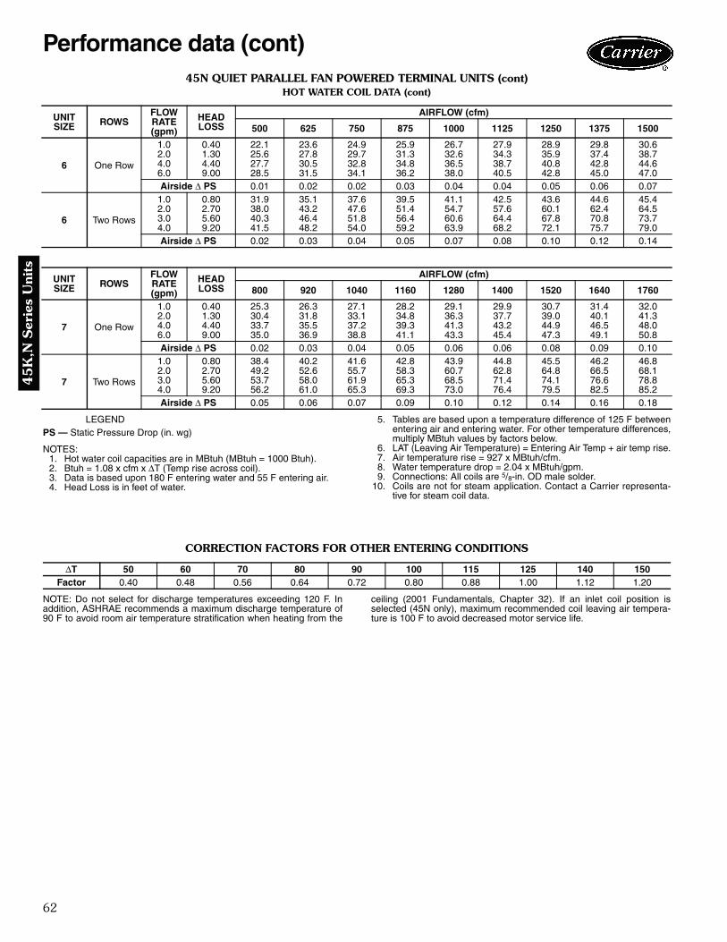
62
45
K,N
Ser
ies
Uni
ts
45N QUIET PARALLEL FAN POWERED TERMINAL UNITS (cont)HOT WATER COIL DATA (cont)
LEGENDPS — Static Pressure Drop (in. wg)
NOTES:1. Hot water coil capacities are in MBtuh (MBtuh = 1000 Btuh).2. Btuh = 1.08 x cfm x ΔT (Temp rise across coil).3. Data is based upon 180 F entering water and 55 F entering air.4. Head Loss is in feet of water.
5. Tables are based upon a temperature difference of 125 F betweenentering air and entering water. For other temperature differences,multiply MBtuh values by factors below.
6. LAT (Leaving Air Temperature) = Entering Air Temp + air temp rise.7. Air temperature rise = 927 x MBtuh/cfm.8. Water temperature drop = 2.04 x MBtuh/gpm.9. Connections: All coils are 5/8-in. OD male solder.
10. Coils are not for steam application. Contact a Carrier representa-tive for steam coil data.
CORRECTION FACTORS FOR OTHER ENTERING CONDITIONS
NOTE: Do not select for discharge temperatures exceeding 120 F. Inaddition, ASHRAE recommends a maximum discharge temperature of90 F to avoid room air temperature stratification when heating from the
ceiling (2001 Fundamentals, Chapter 32). If an inlet coil position isselected (45N only), maximum recommended coil leaving air tempera-ture is 100 F to avoid decreased motor service life.
UNITSIZE ROWS
FLOWRATE(gpm)
HEADLOSS
AIRFLOW (cfm)
500 625 750 875 1000 1125 1250 1375 1500
6 One Row
1.0 0.40 22.1 23.6 24.9 25.9 26.7 27.9 28.9 29.8 30.62.0 1.30 25.6 27.8 29.7 31.3 32.6 34.3 35.9 37.4 38.74.0 4.40 27.7 30.5 32.8 34.8 36.5 38.7 40.8 42.8 44.66.0 9.00 28.5 31.5 34.1 36.2 38.0 40.5 42.8 45.0 47.0Airside Δ PS 0.01 0.02 0.02 0.03 0.04 0.04 0.05 0.06 0.07
6 Two Rows
1.0 0.80 31.9 35.1 37.6 39.5 41.1 42.5 43.6 44.6 45.42.0 2.70 38.0 43.2 47.6 51.4 54.7 57.6 60.1 62.4 64.53.0 5.60 40.3 46.4 51.8 56.4 60.6 64.4 67.8 70.8 73.74.0 9.20 41.5 48.2 54.0 59.2 63.9 68.2 72.1 75.7 79.0Airside Δ PS 0.02 0.03 0.04 0.05 0.07 0.08 0.10 0.12 0.14
UNITSIZE ROWS
FLOWRATE(gpm)
HEADLOSS
AIRFLOW (cfm)
800 920 1040 1160 1280 1400 1520 1640 1760
7 One Row
1.0 0.40 25.3 26.3 27.1 28.2 29.1 29.9 30.7 31.4 32.02.0 1.30 30.4 31.8 33.1 34.8 36.3 37.7 39.0 40.1 41.34.0 4.40 33.7 35.5 37.2 39.3 41.3 43.2 44.9 46.5 48.06.0 9.00 35.0 36.9 38.8 41.1 43.3 45.4 47.3 49.1 50.8Airside Δ PS 0.02 0.03 0.04 0.05 0.06 0.06 0.08 0.09 0.10
7 Two Rows
1.0 0.80 38.4 40.2 41.6 42.8 43.9 44.8 45.5 46.2 46.82.0 2.70 49.2 52.6 55.7 58.3 60.7 62.8 64.8 66.5 68.13.0 5.60 53.7 58.0 61.9 65.3 68.5 71.4 74.1 76.6 78.84.0 9.20 56.2 61.0 65.3 69.3 73.0 76.4 79.5 82.5 85.2Airside Δ PS 0.05 0.06 0.07 0.09 0.10 0.12 0.14 0.16 0.18
ΔT 50 60 70 80 90 100 115 125 140 150Factor 0.40 0.48 0.56 0.64 0.72 0.80 0.88 1.00 1.12 1.20
Performance data (cont)

63
45K
,N S
eries Units
ARI CERTIFICATION RATING POINTS45K QUIET SERIES FAN POWERED TERMINAL UNITS DISCHARGE
45K QUIET SERIES FAN POWERED TERMINAL UNITS RADIATED
45N QUIET PARALLEL FAN POWEREDTERMINAL UNITS DISCHARGE
45N QUIET PARALLEL FAN POWEREDTERMINAL UNITS RADIATED
45N QUIET PARALLEL FAN POWERED TERMINAL UNITS FAN ONLY
LEGEND
Notes for Sound Data Tables:Air Conditioning and Refrigeration Institute (ARI) andASHRAE (American Society of Heating, Refrigeration andAir Conditioning Engineers) provide guidance in both mea-suring sound power levels (per ARI 880-98), and in esti-mating the resultant room sound pressure, typically shownas an NC level (per ARI 885-98 - 2002 addendum - Ap-pendix E). American Society of Heating, Refrigeration,and Air Conditioning Engineers (ASHRAE) handbooksprovide detailed acoustical guidance. Air Conditioning andRefrigeration Institute (ARI) Standard 885 is an application
standard which provides tables and equations for determin-ing acoustical deduction based on the ASHRAE guides, aswell as additional information provided by manufacturers.
All sound data shown by octave bands is raw data with-out any corrections for room absorption or duct attenua-tion. This Sound Power data is tested in accordance withARI Standard 880-98.
The NC values reflect a more accurate sound level esti-mate for typical office spaces or other applications. TheseNC levels are calculated based on procedures from ARIStandard 885-98.
UNITSIZE
FANCFM
FAN ONLY SOUND POWEROctave Bands
2 3 4 5 6 72 400 65 59 54 46 41 433 700 63 62 62 56 57 574 1100 68 67 67 63 60 615 1600 70 68 67 67 64 646 2100 73 72 70 71 69 707 2800 80 78 73 75 73 75
UNITSIZE
INLETSIZE
PRIM.CFM
MINPs
FAN PLUS PRIMARY AT1.5 IN. INLETOctave Bands
2 3 4 5 6 72 8 400 0.10 66 57 55 50 47 433 10 700 0.10 66 60 57 52 46 454 12 1100 0.10 67 64 58 52 50 505 12 1600 0.10 69 64 64 58 53 506 14 2100 0.10 71 66 66 60 55 537 16 2800 0.10 77 69 70 64 59 57
UNITSIZE
FANCFM
FAN ONLY SOUND POWEROctave Bands
2 3 4 5 6 72 400 64 54 50 46 40 333 700 65 57 52 48 41 374 1100 66 61 57 50 45 405 1600 68 62 61 57 49 456 2100 69 63 62 59 52 477 2800 74 68 66 63 58 54
UNITSIZE
INLETSIZE
PRIM.CFM
MINΔ Ps
SOUND POWER AT 1.5 IN. Δ PsOctave Bands
2 3 4 5 6 72 6 400 0.200 61 57 51 45 41 383 8 700 0.200 64 62 53 49 44 394 10 1100 0.200 69 65 57 55 50 445 12 1600 0.200 68 61 57 55 52 456 14 2100 0.200 69 62 60 57 53 467 16 2800 0.200 75 67 65 61 58 52
UNITSIZE
INLETSIZE
PRIM.CFM
MINΔ Ps
SOUND POWER AT 1.5 IN. Δ PsOctave Bands
2 3 4 5 6 72 6 400 0.200 54 48 45 39 37 353 8 700 0.200 62 55 50 44 40 324 10 1100 0.200 63 57 51 45 42 405 12 1600 0.200 65 58 53 48 44 416 14 2100 0.200 70 60 56 50 47 427 16 2800 0.200 74 67 65 62 61 59
UNITSIZE
FANWATTS
FANCFM
FAN ONLY RADIATED SOUND POWER FAN ONLY DISCHARGE SOUND POWEROctave Bands Octave Bands
2 3 4 5 6 7 2 3 4 5 6 72 280 400 66 61 58 53 49 45 65 64 62 57 53 503 300 700 71 69 64 59 53 52 69 69 68 62 60 594 350 800 67 65 61 57 51 50 66 65 65 59 58 565 655 1350 72 67 64 62 60 57 69 66 66 63 62 616 700 1550 73 71 67 63 59 56 71 71 69 65 63 627 1005 1800 75 72 69 67 63 61 74 72 71 68 67 66
Ps — Static PressureΔPs — Difference in Static Pressure from the Inlet to the Discharge

64
45
K,N
Ser
ies
Uni
ts
45K QUIET SERIES FAN POWERED TERMINAL UNITS WITH PSC MOTORRADIATED SOUND POWER DATA
LEGEND NOTES:1. ΔP is the difference in static pressure from the inlet to discharge.2. Sound power levels are in decibels, re: 10-12 watts.3. Radiated sound power is the noise emitted from the unit casing and induc-
tion port.4. Discharge (external) static pressure is 0.25 in. wg.5. All sound data is based on tests conducted in accordance with ARI Stan-
dard 880-98.6. NC Application data based on ARI 885-98 (2002 addendum — Appendix E).
APPLICATION ASSUMPTIONS
UNITSIZE
INLETSIZE(in.)
FLOW RATE MIN ΔPs FAN ONLY FAN + PRIMARY AT 0.5 ΔPs FAN + PRIMARY AT 1.0 ΔPs
CFM L/s in. wg paOctave Band Sound Power,
Lw Lp Octave Band Sound Power, Lw Lp Octave Band Sound Power,
Lw Lp
2 3 4 5 6 7 NC 2 3 4 5 6 7 NC 2 3 4 5 6 7 NC
2 6
200 94 0.025 6.22 56 45 44 39 33 27 — 58 48 46 42 38 30 20 58 49 48 43 40 35 22275 130 0.047 11.76 59 48 46 42 36 29 21 61 51 49 44 40 33 24 61 51 50 45 42 37 24350 165 0.077 19.05 61 50 48 44 38 31 24 64 52 50 46 42 34 27 64 53 52 47 44 39 27425 201 0.113 28.09 63 51 49 45 40 33 26 65 54 52 48 43 36 29 65 55 53 48 45 40 29500 236 0.156 38.88 65 53 50 47 41 34 28 67 55 53 49 45 37 31 67 56 54 49 47 41 31
3 8
600 283 0.073 18.28 59 54 50 45 38 35 24 62 57 53 47 41 38 27 62 57 54 48 43 40 29700 330 0.100 24.88 61 56 52 47 41 37 26 63 58 54 49 43 39 29 63 59 56 50 44 42 30800 378 0.131 32.50 62 57 54 50 43 39 28 65 59 56 52 45 41 30 64 60 57 52 46 43 32900 425 0.165 41.13 64 58 55 52 45 41 30 66 60 55 53 45 41 30 66 61 58 54 47 45 33
1000 472 0.204 50.78 65 59 57 53 46 43 31 67 59 57 53 46 43 31 67 62 59 56 48 46 34
4 10
700 330 0.040 10.08 59 58 50 44 38 33 27 61 58 53 46 41 36 27 61 61 54 47 44 41 30850 401 0.060 14.86 60 59 53 46 40 35 28 62 59 55 46 43 38 29 62 61 56 49 45 43 31
1000 472 0.083 20.57 61 59 55 48 43 37 30 63 59 55 48 45 39 30 63 62 58 51 47 44 321150 543 0.109 27.20 62 60 57 50 44 39 31 64 60 57 50 44 41 31 64 62 59 52 48 46 341300 614 0.140 34.76 63 61 58 51 46 41 33 65 61 58 51 46 41 33 65 63 60 53 49 47 35
5 12
1100 519 0.047 11.76 60 54 56 51 43 38 31 63 57 58 54 47 42 33 64 59 60 54 49 46 351260 595 0.062 15.43 62 56 57 52 45 40 32 65 58 59 55 48 43 34 65 60 61 56 50 47 361425 673 0.079 19.74 64 57 59 54 47 42 34 66 59 59 56 49 45 34 66 61 62 57 50 48 371590 750 0.099 24.57 65 58 60 56 48 44 35 67 58 60 56 48 44 35 67 62 63 58 51 49 381750 826 0.120 29.77 66 60 61 57 50 46 37 66 60 61 57 50 46 37 66 63 64 57 52 50 39
6 14
1400 661 0.044 11.06 62 54 56 52 45 40 31 64 56 58 54 47 43 33 64 59 59 55 49 47 341675 790 0.064 15.83 64 57 58 55 47 43 33 66 57 58 57 49 45 33 67 61 61 57 51 49 371950 920 0.086 21.46 66 59 60 57 50 45 35 68 59 60 59 50 47 35 69 62 63 59 53 50 382225 1050 0.112 27.93 68 61 62 59 52 47 37 68 61 62 59 52 47 37 70 64 64 61 54 52 402500 1180 0.142 35.27 70 63 63 61 53 49 39 70 63 63 61 53 49 39 72 65 66 61 56 53 41
7 16
1500 708 0.029 7.14 68 57 57 53 46 41 32 68 59 57 55 48 45 32 70 59 59 55 48 48 341840 868 0.043 10.75 69 60 60 56 50 45 35 69 62 60 58 52 47 35 72 62 62 58 52 50 372175 1026 0.060 15.01 71 63 62 59 53 48 37 73 65 62 61 55 50 38 73 65 65 61 55 52 402500 1180 0.080 19.84 72 65 64 61 55 51 39 74 67 66 63 57 51 41 74 67 66 63 57 54 422850 1345 0.104 25.78 73 67 66 63 57 53 41 75 69 68 65 59 53 43 76 69 68 65 60 56 44
ARI — Air Conditioning and Refrigeration InstituteCFM — Air Volume (cubic feet per minute)Lp — Room Sound PressureLw — Sound PowerMin ΔPs — Minimum Static Pressure Required to Achieve Rated AirflowNC — ARI 885-98 Test Conditions (see Application Assumptions below)Ps — Static PressurePSC — Permanent Split Capacitor— — Indicates an NC Level less than 20
Sound Power Noise Criteria
ARI 885-98 OCTAVE BANDSRADIATED 2 3 4 5 6 7
Environ. Effect 2 1 0 0 0 0Mineral Tile Space/Ceiling Effect 16 18 20 26 31 36Total Attenuation 18 19 20 26 31 36
Performance data (cont)

65
45K
,N S
eries Units
45K QUIET SERIES FAN POWERED TERMINAL UNITS WITH ECM OPTIONRADIATED SOUND POWER DATA
LEGEND NOTES:1. ΔP is the difference in static pressure from the inlet to discharge.2. Sound power levels are in decibels, re: 10-12 watts.3. Radiated sound power is the noise emitted from the unit casing and induc-
tion port.4. Discharge (external) static pressure is 0.25 in. wg.5. All sound data is based on tests conducted in accordance with ARI Stan-
dard 880-98.6. NC Application data based on ARI 885-98 (2002 addendum — Appendix E).
APPLICATION ASSUMPTIONS
UNITSIZE
INLETSIZE(in.)
FLOW RATE MIN ΔPs FAN ONLY FAN + PRIMARY AT 0.5 ΔPs FAN + PRIMARY AT 1.0 ΔPs
CFM L/s in. wg paOctave Band Sound Power,
Lw Lp Octave Band Sound Power,Lw Lp Octave Band Sound Power,
Lw Lp
2 3 4 5 6 7 NC 2 3 4 5 6 7 NC 2 3 4 5 6 7 NC
4
6
350 165 0.077 19.05 54 55 42 36 29 23 24 59 59 48 41 38 32 28 58 60 51 43 42 39 29400 189 0.100 24.88 55 56 44 37 31 25 25 59 59 50 42 39 33 29 59 61 52 44 43 40 30450 212 0.127 31.49 56 56 45 39 32 27 25 60 60 51 44 40 34 29 60 61 53 45 44 41 31500 236 0.156 38.88 57 57 46 40 33 28 26 61 60 52 45 41 35 30 61 61 54 46 45 42 31550 260 0.189 47.05 57 57 47 41 35 29 26 62 61 52 45 41 36 30 61 62 55 47 45 43 32
8
350 165 0.025 6.22 54 55 42 36 29 23 24 57 58 47 40 36 30 27 57 59 49 42 40 37 28500 236 0.051 12.70 57 57 46 40 33 28 26 60 59 50 43 39 34 29 60 60 52 45 43 40 30650 307 0.086 21.46 58 58 50 43 37 32 27 61 60 53 46 41 36 30 61 61 55 48 45 42 31825 389 0.139 34.56 60 59 52 46 40 35 28 63 61 55 48 44 38 31 63 62 57 50 47 44 32
1000 472 0.204 50.78 61 59 55 48 43 37 30 64 62 57 50 45 40 32 64 63 59 52 48 46 34
10
600 283 0.030 7.40 58 57 49 42 36 31 27 60 57 51 44 39 34 27 60 60 53 46 42 40 29800 378 0.053 13.16 60 59 52 46 40 34 28 62 59 54 47 42 37 29 62 61 55 48 45 42 31
1000 472 0.083 20.57 61 59 55 48 43 37 30 63 59 55 48 45 39 30 63 62 58 51 47 44 321200 566 0.119 29.61 63 60 57 50 45 40 32 65 60 57 50 45 41 32 64 63 59 53 48 46 341400 661 0.162 40.31 64 61 59 52 47 42 34 66 61 59 52 47 42 34 66 63 61 54 50 47 36
6
12
500 236 0.010 2.43 47 39 44 35 29 23 — 52 46 48 43 37 34 22 53 50 50 44 40 39 24800 378 0.025 6.22 54 46 49 43 36 31 24 58 51 53 48 42 38 28 59 55 55 49 45 43 29
1100 519 0.047 11.76 58 51 53 48 41 36 28 62 54 56 52 45 41 31 62 58 58 53 48 46 331400 661 0.077 19.05 62 54 56 52 45 40 31 65 57 59 55 48 44 34 65 60 61 56 50 48 361750 826 0.120 29.77 65 57 59 55 48 43 34 68 60 61 58 51 47 37 68 63 63 59 53 51 38
14
600 283 0.008 2.03 49 42 46 38 32 26 — 53 46 49 44 37 34 23 54 50 51 44 40 39 25900 425 0.018 4.57 55 48 51 45 38 32 25 58 51 53 49 42 38 28 59 54 55 49 44 43 29
1200 566 0.033 8.13 59 52 54 49 42 37 29 62 54 57 52 45 41 31 62 57 58 53 47 45 331500 708 0.051 12.70 63 55 57 53 46 41 32 65 57 59 55 48 44 34 65 60 60 56 50 47 352000 944 0.091 22.57 67 59 61 57 50 46 36 68 59 61 57 50 48 36 69 63 63 59 53 51 39
7 16
600 283 0.005 1.14 60 42 46 40 30 23 22 60 44 46 40 32 35 22 60 44 46 40 33 40 221000 472 0.013 3.17 64 50 52 47 39 33 28 64 52 52 47 41 40 28 64 52 52 47 41 44 281500 708 0.029 7.14 68 57 57 53 46 41 32 68 59 57 55 48 45 32 70 59 59 55 48 48 342000 944 0.051 12.70 70 61 61 57 51 46 36 72 63 61 59 53 49 37 72 63 63 60 53 51 392500 1180 0.080 19.84 72 65 64 61 55 51 39 74 67 66 63 57 51 41 74 67 66 63 57 54 42
ARI — Air Conditioning and Refrigeration InstituteCFM — Air Volume (cubic feet per minute)ECM — Electrically Commutated MotorLp — Room Sound PressureLw — Sound PowerMin ΔPs — Minimum Static Pressure Required to Achieve Rated AirflowNC — ARI 885-98 Test Conditions (see Application Assumptions below)Ps — Static Pressure— — Indicates an NC Level less than 20
Sound Power Noise Criteria
ARI 885-98 OCTAVE BANDSRADIATED 2 3 4 5 6 7
Environ. Effect 2 1 0 0 0 0Mineral Tile Space/Ceiling Effect 16 18 20 26 31 36Total Attenuation 18 19 20 26 31 36
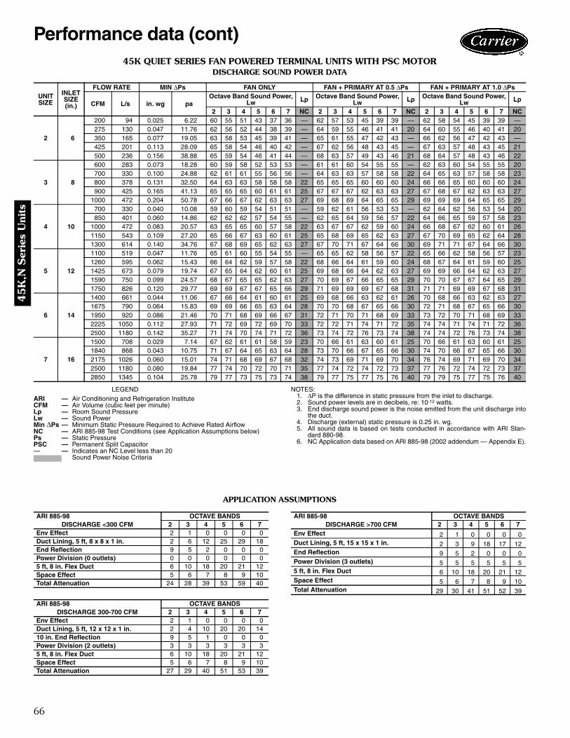
66
45
K,N
Ser
ies
Uni
ts
45K QUIET SERIES FAN POWERED TERMINAL UNITS WITH PSC MOTORDISCHARGE SOUND POWER DATA
LEGEND NOTES:1. ΔP is the difference in static pressure from the inlet to discharge.2. Sound power levels are in decibels, re: 10-12 watts.3. End discharge sound power is the noise emitted from the unit discharge into
the duct.4. Discharge (external) static pressure is 0.25 in. wg.5. All sound data is based on tests conducted in accordance with ARI Stan-
dard 880-98.6. NC Application data based on ARI 885-98 (2002 addendum — Appendix E).
APPLICATION ASSUMPTIONS
UNITSIZE
INLETSIZE(in.)
FLOW RATE MIN ΔPs FAN ONLY FAN + PRIMARY AT 0.5 ΔPs FAN + PRIMARY AT 1.0 ΔPs
CFM L/s in. wg paOctave Band Sound Power,
Lw Lp Octave Band Sound Power,Lw Lp Octave Band Sound Power,
Lw Lp
2 3 4 5 6 7 NC 2 3 4 5 6 7 NC 2 3 4 5 6 7 NC
2 6
200 94 0.025 6.22 60 55 51 43 37 36 — 62 57 53 45 39 39 — 62 58 54 45 39 39 —275 130 0.047 11.76 62 56 52 44 38 39 — 64 59 55 46 41 41 20 64 60 55 46 40 41 20350 165 0.077 19.05 63 58 53 45 39 41 — 65 61 55 47 42 43 — 66 62 56 47 42 43 —425 201 0.113 28.09 65 58 54 46 40 42 — 67 62 56 48 43 45 — 67 63 57 48 43 45 21500 236 0.156 38.88 65 59 54 46 41 44 — 68 63 57 49 43 46 21 68 64 57 48 43 46 22
3 8
600 283 0.073 18.28 60 59 58 52 53 53 — 61 61 60 54 55 55 — 62 63 60 54 55 55 20700 330 0.100 24.88 62 61 61 55 56 56 — 64 63 63 57 58 58 22 64 65 63 57 58 58 23800 378 0.131 32.50 64 63 63 58 58 58 22 65 65 65 60 60 60 24 66 66 65 60 60 60 24900 425 0.165 41.13 65 65 65 60 61 61 25 67 67 67 62 63 63 27 67 68 67 62 63 63 27
1000 472 0.204 50.78 67 66 67 62 63 63 27 69 68 69 64 65 65 29 69 69 69 64 65 65 29
4 10
700 330 0.040 10.08 59 60 59 54 51 51 — 59 62 61 56 53 53 — 62 64 62 56 53 54 20850 401 0.060 14.86 62 62 62 57 54 55 — 62 65 64 59 56 57 22 64 66 65 59 57 58 23
1000 472 0.083 20.57 63 65 65 60 57 58 22 63 67 67 62 59 60 24 66 68 67 62 60 61 261150 543 0.109 27.20 65 66 67 63 60 61 25 65 68 69 65 62 63 27 67 70 69 65 62 64 281300 614 0.140 34.76 67 68 69 65 62 63 27 67 70 71 67 64 66 30 69 71 71 67 64 66 30
5 12
1100 519 0.047 11.76 65 61 60 55 54 55 — 65 65 62 58 56 57 22 65 66 62 58 56 57 231260 595 0.062 15.43 66 64 62 59 57 58 22 68 66 64 61 59 60 24 68 67 64 61 59 60 251425 673 0.079 19.74 67 65 64 62 60 61 25 69 68 66 64 62 63 27 69 69 66 64 62 63 271590 750 0.099 24.57 68 67 65 65 62 63 27 70 69 67 66 65 65 29 70 70 67 67 64 65 291750 826 0.120 29.77 69 69 67 67 65 66 29 71 69 69 69 67 68 31 71 71 69 69 67 68 31
6 14
1400 661 0.044 11.06 67 66 64 61 60 61 25 69 68 66 63 62 61 26 70 68 66 63 62 63 271675 790 0.064 15.83 69 69 66 65 63 64 28 70 70 68 67 65 66 30 72 71 68 67 65 66 301950 920 0.086 21.46 70 71 68 69 66 67 31 72 71 70 71 68 69 33 73 72 70 71 68 69 332225 1050 0.112 27.93 71 72 69 72 69 70 33 72 72 71 74 71 72 35 74 74 71 74 71 72 362500 1180 0.142 35.27 71 74 70 74 71 72 36 73 74 72 76 73 74 38 74 74 72 76 73 74 38
7 16
1500 708 0.029 7.14 67 62 61 61 58 59 23 70 66 61 63 60 61 25 70 66 61 63 60 61 251840 868 0.043 10.75 71 67 64 65 63 64 28 73 70 66 67 65 66 30 74 70 66 67 65 66 302175 1026 0.060 15.01 74 71 68 69 67 68 32 74 73 69 71 69 70 34 76 74 69 71 69 70 342500 1180 0.080 19.84 77 74 70 72 70 71 35 77 74 72 74 72 73 37 77 76 72 74 72 73 372850 1345 0.104 25.78 79 77 73 75 73 74 38 79 77 75 77 75 76 40 79 79 75 77 75 76 40
ARI — Air Conditioning and Refrigeration InstituteCFM — Air Volume (cubic feet per minute)Lp — Room Sound PressureLw — Sound PowerMin ΔPs — Minimum Static Pressure Required to Achieve Rated AirflowNC — ARI 885-98 Test Conditions (see Application Assumptions below)Ps — Static PressurePSC — Permanent Split Capacitor— — Indicates an NC Level less than 20
Sound Power Noise Criteria
ARI 885-98 OCTAVE BANDSDISCHARGE <300 CFM 2 3 4 5 6 7
Env Effect 2 1 0 0 0 0Duct Lining, 5 ft, 8 x 8 x 1 in. 2 6 12 25 29 18End Reflection 9 5 2 0 0 0Power Division (0 outlets) 0 0 0 0 0 05 ft, 8 in. Flex Duct 6 10 18 20 21 12Space Effect 5 6 7 8 9 10Total Attenuation 24 28 39 53 59 40
ARI 885-98 OCTAVE BANDSDISCHARGE 300-700 CFM 2 3 4 5 6 7
Env Effect 2 1 0 0 0 0Duct Lining, 5 ft, 12 x 12 x 1 in. 2 4 10 20 20 1410 in. End Reflection 9 5 1 0 0 0Power Division (2 outlets) 3 3 3 3 3 35 ft, 8 in. Flex Duct 6 10 18 20 21 12Space Effect 5 6 7 8 9 10Total Attenuation 27 29 40 51 53 39
ARI 885-98 OCTAVE BANDSDISCHARGE >700 CFM 2 3 4 5 6 7
Env Effect 2 1 0 0 0 0Duct Lining, 5 ft, 15 x 15 x 1 in. 2 3 9 18 17 12End Reflection 9 5 2 0 0 0Power Division (3 outlets) 5 5 5 5 5 55 ft, 8 in. Flex Duct 6 10 18 20 21 12Space Effect 5 6 7 8 9 10Total Attenuation 29 30 41 51 52 39
Performance data (cont)

67
45K
,N S
eries Units
45K QUIET SERIES FAN POWERED TERMINAL UNITS WITH ECM OPTIONDISCHARGE SOUND POWER DATA
LEGEND NOTES:1. ΔP is the difference in static pressure from the inlet to discharge.2. Sound power levels are in decibels, re: 10-12 watts.3. End discharge sound power is the noise emitted from the unit discharge into
the duct.4. Discharge (external) static pressure is 0.25 in. wg.5. All sound data is based on tests conducted in accordance with ARI Stan-
dard 880-98.6. NC Application data based on ARI 885-98 (2002 addendum — Appendix E).
APPLICATION ASSUMPTIONS
UNITSIZE
INLETSIZE(in.)
FLOW RATE MIN ΔPs FAN ONLY FAN + PRIMARY AT 0.5 ΔPs FAN + PRIMARY AT 1.0 ΔPs
CFM L/s in. wg paOctave Band Sound Power,
Lw Lp Octave Band Sound Power,Lw Lp Octave Band Sound Power,
Lw Lp
2 3 4 5 6 7 NC 2 3 4 5 6 7 NC 2 3 4 5 6 7 NC
4
6
350 165 0.077 19.05 51 51 49 41 38 36 — 55 56 53 45 43 41 — 56 59 53 45 43 42 —400 189 0.100 24.88 53 52 51 43 41 39 — 56 58 55 47 45 44 — 57 60 55 48 46 45 —450 212 0.127 31.49 54 54 53 46 43 42 — 58 59 56 50 47 46 — 59 61 57 50 48 47 —500 236 0.156 38.88 55 55 54 47 45 44 — 59 61 58 52 49 48 — 60 63 59 52 50 49 20550 260 0.189 47.05 56 57 56 49 46 46 — 60 62 59 53 51 50 — 61 64 60 54 51 51 22
8
350 165 0.025 6.22 51 51 49 41 38 36 — 54 55 52 44 41 40 — 55 57 52 44 42 40 —500 236 0.051 12.70 55 55 54 47 45 44 — 58 59 57 50 48 47 — 59 61 58 51 48 48 —650 307 0.086 21.46 58 59 58 52 49 49 — 61 62 61 55 52 52 20 62 64 61 55 53 53 22825 389 0.139 34.56 61 62 62 57 54 54 — 64 65 65 59 57 57 22 64 67 65 60 57 58 24
1000 472 0.204 50.78 63 65 65 60 57 58 22 66 68 67 63 60 61 25 67 69 68 63 61 62 27
10
600 283 0.030 7.40 57 58 57 51 48 47 — 59 60 59 53 50 50 — 60 62 59 53 51 50 —800 378 0.053 13.16 61 62 61 56 53 53 20 61 64 63 58 55 56 23 63 65 64 58 56 56 25
1000 472 0.083 20.57 63 65 65 60 57 58 22 63 67 67 62 59 60 24 66 68 67 62 60 61 261200 566 0.119 29.61 66 67 67 63 60 62 26 66 69 69 65 63 64 28 68 70 70 66 63 65 291400 661 0.162 40.31 67 69 70 66 63 65 29 67 71 72 68 65 67 31 70 72 72 68 66 68 32
6
12
500 236 0.010 2.43 60 53 54 38 40 41 — 63 57 56 41 43 43 — 65 57 57 41 43 43 —800 378 0.025 6.22 63 59 59 49 49 50 — 66 62 61 52 52 52 23 68 63 61 52 52 53 25
1100 519 0.047 11.76 66 63 62 56 55 56 20 68 66 65 59 58 59 23 70 66 65 59 58 59 241400 661 0.077 19.05 67 66 64 61 60 61 25 70 69 67 64 63 63 27 72 69 67 64 63 64 271750 826 0.120 29.77 69 69 67 66 64 65 29 72 72 69 69 67 68 32 73 72 70 69 67 68 32
14
600 283 0.008 2.03 61 55 56 42 44 45 — 63 58 57 45 45 45 — 65 58 58 45 46 45 —900 425 0.018 4.57 64 60 60 51 51 52 — 66 63 62 54 53 52 — 67 63 62 54 53 52 —
1200 566 0.033 8.13 66 64 63 58 57 58 22 68 66 65 60 59 58 24 69 67 65 60 59 60 241500 708 0.051 12.70 68 67 65 63 61 62 26 70 69 67 65 63 62 27 71 69 67 65 63 64 282000 944 0.091 22.57 70 71 68 69 67 68 31 72 71 70 71 69 69 33 73 73 70 71 69 70 34
7 16
600 283 0.005 1.14 50 41 43 41 36 36 — 56 49 43 43 36 39 — 57 50 43 43 36 38 —1000 472 0.013 3.17 59 53 53 52 48 49 — 63 58 53 54 50 51 — 64 59 53 54 50 51 —1400 661 0.029 7.14 66 61 59 59 56 57 21 69 64 59 61 58 59 23 69 65 59 61 58 59 231900 897 0.051 12.70 72 68 65 66 63 64 28 74 70 67 68 65 67 30 74 71 67 68 65 67 302500 1180 0.080 19.84 77 74 70 72 70 71 35 77 74 72 74 72 73 37 77 76 72 74 72 73 37
ARI — Air Conditioning and Refrigeration InstituteCFM — Air Volume (cubic feet per minute)ECM — Electrically Commutated MotorLp — Room Sound PressureLw — Sound PowerMin ΔPs — Minimum Static Pressure Required to Achieve Rated AirflowNC — ARI 885-98 Test Conditions (see Application Assumptions below)Ps — Static Pressure— — Indicates an NC Level less than 20
Sound Power Noise Criteria
ARI 885-98 OCTAVE BANDSDISCHARGE <300 CFM 2 3 4 5 6 7
Env Effect 2 1 0 0 0 0Duct Lining, 5 ft, 8 x 8 x 1 in. 2 6 12 25 29 18End Reflection 9 5 2 0 0 0Power Division (0 outlets) 0 0 0 0 0 05 ft, 8 in. Flex Duct 6 10 18 20 21 12Space Effect 5 6 7 8 9 10Total Attenuation 24 28 39 53 59 40
ARI 885-98 OCTAVE BANDSDISCHARGE 300-700 CFM 2 3 4 5 6 7
Env Effect 2 1 0 0 0 0Duct Lining, 5 ft, 12 x 12 x 1 in. 2 4 10 20 20 1410 in. End Reflection 9 5 1 0 0 0Power Division (2 outlets) 3 3 3 3 3 35 ft, 8 in. Flex Duct 6 10 18 20 21 12Space Effect 5 6 7 8 9 10Total Attenuation 27 29 40 51 53 39
ARI 885-98 OCTAVE BANDSDISCHARGE >700 CFM 2 3 4 5 6 7
Env Effect 2 1 0 0 0 0Duct Lining, 5 ft, 15 x 15 x 1 in. 2 3 9 18 17 12End Reflection 9 5 2 0 0 0Power Division (3 outlets) 5 5 5 5 5 55 ft, 8 in. Flex Duct 6 10 18 20 21 12Space Effect 5 6 7 8 9 10Total Attenuation 29 30 41 51 52 39

68
45
K,N
Ser
ies
Uni
ts
45N QUIET PARALLEL FAN POWERED TERMINAL UNITS WITH PSC MOTORPRIMARY RADIATED SOUND POWER DATA — 100% PRIMARY
LEGEND
APPLICATION ASSUMPTIONS
NOTE: Ceiling type — Mineral Fiber, 5/8 in. — 35 lb/cu ft.
NOTES:1. ΔP is the difference in static pressure from the inlet to discharge.2. Sound power levels are in decibels, re: 10-12 watts.3. Radiated sound power is the noise emitted from the unit casing and induc-
tion port.4. Discharge (external) static pressure is 0.25 in. wg.5. All sound data is based on tests conducted in accordance with ARI Stan-
dard 880-98.6. NC Application data based on ARI 885-98 (2002 addendum — Appendix E).
UNITSIZE
INLETSIZE(in.)
FLOW RATE MIN ΔPs PRIMARY AT 0.5 ΔPs PRIMARY AT 1.0 ΔPs PRIMARY AT 2.0 ΔPs
CFM L/s in. wg paOctave Band Sound Power,
Lw Lp Octave Band Sound Power,Lw Lp Octave Band Sound Power,
Lw Lp
2 3 4 5 6 7 NC 2 3 4 5 6 7 NC 2 3 4 5 6 7 NC
2 6
100 47 0.013 3.1 35 29 26 23 23 23 — 37 31 29 26 27 28 — 39 33 31 29 31 33 —200 94 0.050 12.4 43 37 34 29 27 25 — 45 39 37 32 31 30 — 47 41 39 35 35 35 —300 142 0.113 28.0 48 42 39 33 30 27 — 50 44 41 36 34 32 — 52 46 44 39 38 37 —400 189 0.200 49.8 51 46 42 36 31 28 — 54 47 44 39 36 33 — 56 49 47 42 40 38 21500 236 0.313 77.8 54 48 44 38 33 28 — 56 50 47 41 37 33 21 58 52 49 44 41 38 24
3 8
180 85 0.013 3.3 35 33 32 26 22 21 — 39 37 36 30 26 28 — 42 40 40 33 30 34 —360 170 0.053 13.2 44 40 38 33 29 26 — 47 44 42 36 33 33 — 51 47 46 40 38 39 —540 255 0.119 29.6 49 44 41 37 33 29 — 52 48 45 40 38 36 — 56 51 49 44 42 42 23720 340 0.212 52.7 52 47 44 39 36 31 — 56 51 48 43 41 38 21 59 54 51 47 45 44 26900 425 0.331 82.3 55 50 45 42 39 33 — 59 53 49 45 43 39 24 62 56 53 49 48 46 28
4 10
290 137 0.014 3.5 39 34 32 25 19 16 — 43 37 35 29 22 21 — 47 40 38 32 26 26 —580 274 0.056 13.8 47 42 40 33 28 24 — 51 46 43 37 31 29 — 56 49 46 40 35 34 —870 411 0.125 31.1 52 47 44 38 33 29 — 57 51 47 42 37 34 21 61 54 50 45 40 39 25
1160 547 0.222 55.3 56 51 47 42 37 32 21 60 54 51 45 41 37 25 64 58 54 48 44 42 281450 684 0.348 86.5 59 54 50 44 40 34 24 63 57 53 48 43 39 27 67 61 56 51 47 44 31
5 12
420 198 0.014 3.4 38 37 34 32 26 20 — 41 40 38 35 30 25 — 44 43 42 38 33 30 —840 396 0.055 13.7 49 45 41 38 33 28 — 52 48 45 41 37 33 — 55 51 49 44 40 38 23
1260 595 0.124 30.9 55 49 45 42 37 32 — 58 53 49 45 40 37 23 61 56 52 48 44 42 271680 793 0.221 54.9 59 53 47 44 40 35 21 62 56 51 47 43 40 26 66 59 55 51 47 46 302100 991 0.345 85.7 63 55 49 46 42 38 26 66 58 53 49 45 43 30 69 61 57 52 49 48 34
6 14
570 269 0.015 3.7 44 39 37 32 26 22 — 48 44 41 35 30 28 — 53 48 46 39 34 34 —1140 538 0.059 14.7 53 47 44 39 34 28 — 57 51 48 42 38 34 22 62 56 53 46 42 40 271710 807 0.133 33.0 58 51 48 43 39 32 22 63 55 52 47 43 38 27 67 60 57 50 47 44 322280 1076 0.236 58.7 62 54 51 46 42 35 25 67 58 55 50 46 41 30 71 63 60 53 50 47 362850 1345 0.368 91.7 65 56 53 48 45 37 28 69 61 57 52 49 43 34 74 65 62 56 53 49 40
7 16
740 349 0.014 3.5 49 43 40 36 31 27 — 54 49 46 43 39 37 — 60 55 52 50 46 47 271480 698 0.056 13.9 57 50 48 44 39 34 22 63 56 54 51 47 44 28 68 62 60 58 55 54 352220 1048 0.126 31.3 62 55 52 48 44 38 26 68 60 58 55 52 48 33 73 66 64 62 60 58 402960 1397 0.224 55.6 66 58 55 51 48 41 30 71 63 61 58 56 51 37 77 69 68 65 63 61 443700 1746 0.349 86.9 68 60 58 54 51 44 33 74 66 64 61 58 54 40 80 72 70 68 66 64 47
ARI — Air Conditioning and Refrigeration InstituteCFM — Air Volume (cubic feet per minute)Lp — Room Sound PressureLw — Sound PowerMin ΔPs — Minimum Static Pressure Required to Achieve Rated AirflowNC — ARI 885-98 Test Conditions (see Application Assumptions below)Ps — Static PressurePSC — Permanent Split Capacitor— — Indicates an NC Level less than 20
Sound Power Noise Criteria
ARI 885-98RADIATED ATTENUATION VALUES
Octave Bands2 3 4 5 6 7
Environ. Effect 2 1 0 0 0 0Plenum/Room Effect 16 18 20 26 31 36Total Attenuation 18 19 20 26 31 36
Performance data (cont)
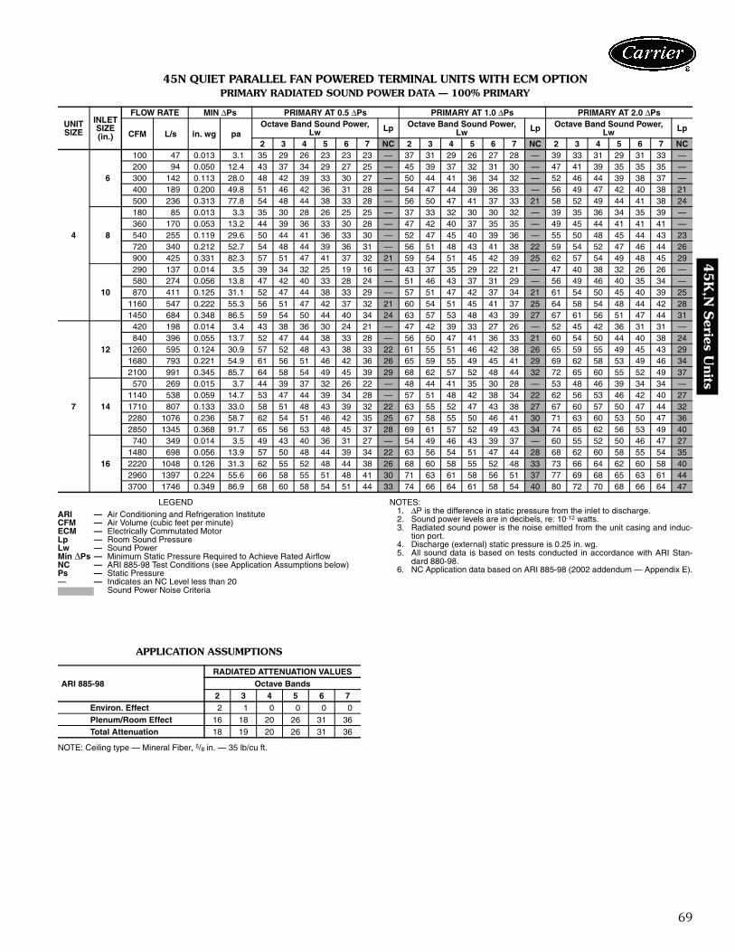
69
45K
,N S
eries Units
45N QUIET PARALLEL FAN POWERED TERMINAL UNITS WITH ECM OPTIONPRIMARY RADIATED SOUND POWER DATA — 100% PRIMARY
LEGEND
APPLICATION ASSUMPTIONS
NOTE: Ceiling type — Mineral Fiber, 5/8 in. — 35 lb/cu ft.
NOTES:1. ΔP is the difference in static pressure from the inlet to discharge.2. Sound power levels are in decibels, re: 10-12 watts.3. Radiated sound power is the noise emitted from the unit casing and induc-
tion port.4. Discharge (external) static pressure is 0.25 in. wg.5. All sound data is based on tests conducted in accordance with ARI Stan-
dard 880-98.6. NC Application data based on ARI 885-98 (2002 addendum — Appendix E).
UNITSIZE
INLETSIZE(in.)
FLOW RATE MIN ΔPs PRIMARY AT 0.5 ΔPs PRIMARY AT 1.0 ΔPs PRIMARY AT 2.0 ΔPs
CFM L/s in. wg paOctave Band Sound Power,
Lw Lp Octave Band Sound Power,Lw Lp Octave Band Sound Power,
Lw Lp
2 3 4 5 6 7 NC 2 3 4 5 6 7 NC 2 3 4 5 6 7 NC
4
6
100 47 0.013 3.1 35 29 26 23 23 23 — 37 31 29 26 27 28 — 39 33 31 29 31 33 —200 94 0.050 12.4 43 37 34 29 27 25 — 45 39 37 32 31 30 — 47 41 39 35 35 35 —300 142 0.113 28.0 48 42 39 33 30 27 — 50 44 41 36 34 32 — 52 46 44 39 38 37 —400 189 0.200 49.8 51 46 42 36 31 28 — 54 47 44 39 36 33 — 56 49 47 42 40 38 21500 236 0.313 77.8 54 48 44 38 33 28 — 56 50 47 41 37 33 21 58 52 49 44 41 38 24
8
180 85 0.013 3.3 35 30 28 26 25 25 — 37 33 32 30 30 32 — 39 35 36 34 35 39 —360 170 0.053 13.2 44 39 36 33 30 28 — 47 42 40 37 35 35 — 49 45 44 41 41 41 —540 255 0.119 29.6 50 44 41 36 33 30 — 52 47 45 40 39 36 — 55 50 48 45 44 43 23720 340 0.212 52.7 54 48 44 39 36 31 — 56 51 48 43 41 38 22 59 54 52 47 46 44 26900 425 0.331 82.3 57 51 47 41 37 32 21 59 54 51 45 42 39 25 62 57 54 49 48 45 29
10
290 137 0.014 3.5 39 34 32 25 19 16 — 43 37 35 29 22 21 — 47 40 38 32 26 26 —580 274 0.056 13.8 47 42 40 33 28 24 — 51 46 43 37 31 29 — 56 49 46 40 35 34 —870 411 0.125 31.1 52 47 44 38 33 29 — 57 51 47 42 37 34 21 61 54 50 45 40 39 25
1160 547 0.222 55.3 56 51 47 42 37 32 21 60 54 51 45 41 37 25 64 58 54 48 44 42 281450 684 0.348 86.5 59 54 50 44 40 34 24 63 57 53 48 43 39 27 67 61 56 51 47 44 31
7
12
420 198 0.014 3.4 43 38 36 30 24 21 — 47 42 39 33 27 26 — 52 45 42 36 31 31 —840 396 0.055 13.7 52 47 44 38 33 28 — 56 50 47 41 36 33 21 60 54 50 44 40 38 24
1260 595 0.124 30.9 57 52 48 43 38 33 22 61 55 51 46 42 38 26 65 59 55 49 45 43 291680 793 0.221 54.9 61 56 51 46 42 36 26 65 59 55 49 45 41 29 69 62 58 53 49 46 342100 991 0.345 85.7 64 58 54 49 45 39 29 68 62 57 52 48 44 32 72 65 60 55 52 49 37
14
570 269 0.015 3.7 44 39 37 32 26 22 — 48 44 41 35 30 28 — 53 48 46 39 34 34 —1140 538 0.059 14.7 53 47 44 39 34 28 — 57 51 48 42 38 34 22 62 56 53 46 42 40 271710 807 0.133 33.0 58 51 48 43 39 32 22 63 55 52 47 43 38 27 67 60 57 50 47 44 322280 1076 0.236 58.7 62 54 51 46 42 35 25 67 58 55 50 46 41 30 71 63 60 53 50 47 362850 1345 0.368 91.7 65 56 53 48 45 37 28 69 61 57 52 49 43 34 74 65 62 56 53 49 40
16
740 349 0.014 3.5 49 43 40 36 31 27 — 54 49 46 43 39 37 — 60 55 52 50 46 47 271480 698 0.056 13.9 57 50 48 44 39 34 22 63 56 54 51 47 44 28 68 62 60 58 55 54 352220 1048 0.126 31.3 62 55 52 48 44 38 26 68 60 58 55 52 48 33 73 66 64 62 60 58 402960 1397 0.224 55.6 66 58 55 51 48 41 30 71 63 61 58 56 51 37 77 69 68 65 63 61 443700 1746 0.349 86.9 68 60 58 54 51 44 33 74 66 64 61 58 54 40 80 72 70 68 66 64 47
ARI — Air Conditioning and Refrigeration InstituteCFM — Air Volume (cubic feet per minute)ECM — Electrically Commutated MotorLp — Room Sound PressureLw — Sound PowerMin ΔPs — Minimum Static Pressure Required to Achieve Rated AirflowNC — ARI 885-98 Test Conditions (see Application Assumptions below)Ps — Static Pressure— — Indicates an NC Level less than 20
Sound Power Noise Criteria
ARI 885-98RADIATED ATTENUATION VALUES
Octave Bands2 3 4 5 6 7
Environ. Effect 2 1 0 0 0 0Plenum/Room Effect 16 18 20 26 31 36Total Attenuation 18 19 20 26 31 36
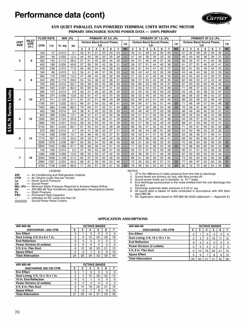
70
45
K,N
Ser
ies
Uni
ts
45N QUIET PARALLEL FAN POWERED TERMINAL UNITS WITH PSC MOTORPRIMARY DISCHARGE SOUND POWER DATA — 100% PRIMARY
LEGEND NOTES:1. ΔP is the difference in static pressure from the inlet to discharge.2. Sound levels are primary air only, with fans turned off.3. Sound power levels are in decibels, re: 10-12 watts.4. End discharge sound power is the noise emitted from the unit discharge into
the duct.5. Discharge (external) static pressure is 0.25 in. wg.6. All sound data is based on tests conducted in accordance with ARI Stan-
dard 880-98.7. NC Application data based on ARI 885-98 (2002 addendum — Appendix E).
APPLICATION ASSUMPTIONS
UNITSIZE
INLETSIZE(in.)
FLOW RATE MIN ΔPs PRIMARY AT 0.5 ΔPs PRIMARY AT 1.0 ΔPs PRIMARY AT 2.0 ΔPs
CFM L/s in. wg paOctave Band Sound Power,
Lw Lp Octave Band Sound Power,Lw Lp Octave Band Sound Power,
Lw Lp
2 3 4 5 6 7 NC 2 3 4 5 6 7 NC 2 3 4 5 6 7 NC
2 6
100 47 0.013 3.1 32 31 27 23 23 24 — 35 31 28 24 26 29 — 37 32 28 25 29 34 —200 94 0.050 12.4 44 43 39 33 30 28 — 47 44 39 34 33 32 — 49 45 40 36 36 37 —300 142 0.113 28.0 51 51 45 39 34 30 — 54 51 46 40 37 35 — 56 52 47 41 40 39 —400 189 0.200 49.8 57 56 50 43 36 31 — 59 57 51 44 40 36 — 61 57 51 46 43 41 —500 236 0.313 77.8 60 60 54 46 39 33 — 63 61 54 47 42 37 — 65 61 55 49 45 42 —
3 8
180 85 0.013 3.3 35 41 40 31 26 23 — 39 43 42 33 29 28 — 43 46 45 36 33 33 —360 170 0.053 13.2 47 49 45 38 32 28 — 51 52 47 40 36 33 — 55 55 50 43 39 37 —540 255 0.119 29.6 54 54 48 42 36 31 — 58 57 50 45 39 35 — 62 60 53 47 43 40 —720 340 0.212 52.7 59 58 50 45 39 33 — 63 60 53 48 42 37 — 67 63 55 50 46 42 —900 425 0.331 82.3 63 60 52 47 41 34 — 67 63 54 50 44 39 — 71 66 57 52 48 44 23
4 10
290 137 0.014 3.5 40 41 40 33 26 20 — 43 43 42 36 29 23 — 45 46 45 38 32 27 —580 274 0.056 13.8 53 51 47 43 37 30 — 56 53 49 45 40 34 — 58 56 52 48 43 37 —870 411 0.125 31.1 61 57 51 48 43 36 — 63 59 54 51 46 40 — 66 62 56 53 49 43 —
1160 547 0.222 55.3 66 61 54 52 48 41 — 69 64 57 55 51 44 20 71 66 59 57 54 48 231450 684 0.348 86.5 70 64 57 55 51 44 22 73 67 59 58 54 48 25 75 69 61 60 57 51 28
5 12
420 198 0.014 3.4 38 41 42 33 25 20 — 43 45 45 37 29 26 — 48 49 49 40 33 31 —840 396 0.055 13.7 48 47 47 42 35 28 — 53 51 51 45 39 34 — 58 55 54 48 43 39 —
1260 595 0.124 30.9 54 51 50 46 41 33 — 59 55 54 49 45 38 — 64 59 57 53 49 44 —1680 793 0.221 54.9 58 53 53 50 45 36 — 63 57 56 53 49 42 — 68 61 59 56 53 47 —2100 991 0.345 85.7 61 55 54 52 48 39 — 66 59 57 55 52 44 — 71 63 61 59 56 50 23
6 14
570 269 0.015 3.7 45 41 39 34 27 21 — 49 46 44 38 31 26 — 54 50 48 42 35 32 —1140 538 0.059 14.7 54 48 46 43 37 31 — 59 53 51 47 42 36 — 63 58 56 51 46 41 —1710 807 0.133 33.0 59 53 51 48 44 36 — 64 58 56 52 48 41 — 68 62 60 56 52 47 —2280 1076 0.236 58.7 63 56 54 52 48 40 — 68 61 59 56 52 45 — 72 66 63 60 56 50 242850 1345 0.368 91.7 66 58 56 54 51 43 — 71 63 61 58 55 48 22 75 68 66 62 60 53 28
7 16
740 349 0.014 3.5 47 43 43 38 31 23 — 52 47 47 42 35 28 — 56 51 51 45 38 32 —1480 698 0.056 13.9 58 52 50 47 42 35 — 62 56 55 51 46 39 — 67 60 59 54 49 44 —2220 1048 0.126 31.3 64 57 55 52 49 42 — 68 61 59 56 52 46 — 73 65 64 60 56 50 252960 1397 0.224 55.6 68 61 58 56 53 46 — 73 65 63 60 57 51 25 77 69 67 63 60 55 313700 1746 0.349 86.9 71 64 61 59 57 50 23 76 68 65 63 60 55 29 80 72 70 66 64 59 35
ARI — Air Conditioning and Refrigeration InstituteCFM — Air Volume (cubic feet per minute)Lp — Room Sound PressureLw — Sound PowerMin ΔPs — Minimum Static Pressure Required to Achieve Rated AirflowNC — ARI 885-98 Test Conditions (see Application Assumptions below)Ps — Static PressurePSC — Permanent Split Capacitor— — Indicates an NC Level less than 20
Sound Power Noise Criteria
ARI 885-98 OCTAVE BANDSDISCHARGE <300 CFM 2 3 4 5 6 7
Env Effect 2 1 0 0 0 0Duct Lining, 5 ft, 8 x 8 x 1 in. 2 6 12 25 29 18End Reflection 9 5 2 0 0 0Power Division (0 outlets) 0 0 0 0 0 05 ft, 8 in. Flex Duct 6 10 18 20 21 12Space Effect 5 6 7 8 9 10Total Attenuation 24 28 39 53 59 40
ARI 885-98 OCTAVE BANDSDISCHARGE 300-700 CFM 2 3 4 5 6 7
Env Effect 2 1 0 0 0 0Duct Lining, 5 ft, 12 x 12 x 1 in. 2 4 10 20 20 1410 in. End Reflection 9 5 1 0 0 0Power Division (2 outlets) 3 3 3 3 3 35 ft, 8 in. Flex Duct 6 10 18 20 21 12Space Effect 5 6 7 8 9 10Total Attenuation 27 29 40 51 53 39
ARI 885-98 OCTAVE BANDSDISCHARGE >700 CFM 2 3 4 5 6 7
Env Effect 2 1 0 0 0 0Duct Lining, 5 ft, 15 x 15 x 1 in. 2 3 9 18 17 12End Reflection 9 5 2 0 0 0Power Division (3 outlets) 5 5 5 5 5 55 ft, 8 in. Flex Duct 6 10 18 20 21 12Space Effect 5 6 7 8 9 10Total Attenuation 29 30 41 51 52 39
Performance data (cont)

71
45K
,N S
eries Units
45N QUIET PARALLEL FAN POWERED TERMINAL UNITS WITH ECM MOTORPRIMARY DISCHARGE SOUND POWER DATA — 100% PRIMARY
LEGEND NOTES:1. ΔP is the difference in static pressure from the inlet to discharge.2. Sound levels are primary air only, with fans turned off.3. Sound power levels are in decibels, re: 10-12 watts.4. End discharge sound power is the noise emitted from the unit discharge into
the duct.5. Discharge (external) static pressure is 0.25 in. wg.6. All sound data is based on tests conducted in accordance with ARI Stan-
dard 880-98.7. NC Application data based on ARI 885-98 (2002 addendum — Appendix E).
APPLICATION ASSUMPTIONS
UNITSIZE
INLETSIZE(in.)
FLOW RATE MIN Ps PRIMARY AT 0.5 Ps PRIMARY AT 1.0 Ps PRIMARY AT 2.0 Ps
CFM L/s in. wg paOctave Band Sound Power,
Lw Lp Octave Band Sound Power,Lw Lp Octave Band Sound Power,
Lw Lp
2 3 4 5 6 7 NC 2 3 4 5 6 7 NC 2 3 4 5 6 7 NC
4
6
100 47 0.013 3.1 32 31 27 23 23 24 — 35 31 28 24 26 29 — 37 32 28 25 29 34 —200 94 0.050 12.4 44 43 39 33 30 28 — 47 44 39 34 33 32 — 49 45 40 36 36 37 —300 142 0.113 28.0 51 51 45 39 34 30 — 54 51 46 40 37 35 — 56 52 47 41 40 39 —400 189 0.200 49.8 57 56 50 43 36 31 — 59 57 51 44 40 36 — 61 57 51 46 43 41 —500 236 0.313 77.8 60 60 54 46 39 33 — 63 61 54 47 42 37 — 65 61 55 49 45 42 —
8
180 85 0.013 3.3 35 41 40 31 26 23 — 39 43 42 33 29 28 — 43 46 45 36 33 33 —360 170 0.053 13.2 47 49 45 38 32 28 — 51 52 47 40 36 33 — 55 55 50 43 39 37 —540 255 0.119 29.6 54 54 48 42 36 31 — 58 57 50 45 39 35 — 62 60 53 47 43 40 —720 340 0.212 52.7 59 58 50 45 39 33 — 63 60 53 48 42 37 — 67 63 55 50 46 42 —900 425 0.331 82.3 63 60 52 47 41 34 — 67 63 54 50 44 39 — 71 66 57 52 48 44 23
10
290 137 0.014 3.5 40 41 40 33 26 20 — 43 43 42 36 29 23 — 45 46 45 38 32 27 —580 274 0.056 13.8 53 51 47 43 37 30 — 56 53 49 45 40 34 — 58 56 52 48 43 37 —870 411 0.125 31.1 61 57 51 48 43 36 — 63 59 54 51 46 40 — 66 62 56 53 49 43 —
1160 547 0.222 55.3 66 61 54 52 48 41 — 69 64 57 55 51 44 20 71 66 59 57 54 48 231450 684 0.348 86.5 70 64 57 55 51 44 22 73 67 59 58 54 48 25 75 69 61 60 57 51 28
7
12
420 198 0.014 3.4 38 41 42 33 25 20 — 43 45 45 37 29 26 — 48 49 49 40 33 31 —840 396 0.055 13.7 48 47 47 42 35 28 — 53 51 51 45 39 34 — 58 55 54 48 43 39 —
1260 595 0.124 30.9 54 51 50 46 41 33 — 59 55 54 49 45 38 — 64 59 57 53 49 44 —1680 793 0.221 54.9 58 53 53 50 45 36 — 63 57 56 53 49 42 — 68 61 59 56 53 47 —2100 991 0.345 85.7 61 55 54 52 48 39 — 66 59 57 55 52 44 — 71 63 61 59 56 50 23
14
570 269 0.015 3.7 45 41 39 34 27 21 — 49 46 44 38 31 26 — 54 50 48 42 35 32 —1140 538 0.059 14.7 54 48 46 43 37 31 — 59 53 51 47 42 36 — 63 58 56 51 46 41 —1710 807 0.133 33.0 59 53 51 48 44 36 — 64 58 56 52 48 41 — 68 62 60 56 52 47 —2280 1076 0.236 58.7 63 56 54 52 48 40 — 68 61 59 56 52 45 — 72 66 63 60 56 50 242850 1345 0.368 91.7 66 58 56 54 51 43 — 71 63 61 58 55 48 22 75 68 66 62 60 53 28
16
740 349 0.014 3.5 47 43 43 38 31 23 — 52 47 47 42 35 28 — 56 51 51 45 38 32 —1480 698 0.056 13.9 58 52 50 47 42 35 — 62 56 55 51 46 39 — 67 60 59 54 49 44 —2220 1048 0.126 31.3 64 57 55 52 49 42 — 68 61 59 56 52 46 — 73 65 64 60 56 50 252960 1397 0.224 55.6 68 61 58 56 53 46 — 73 65 63 60 57 51 25 77 69 67 63 60 55 313700 1746 0.349 86.9 71 64 61 59 57 50 23 76 68 65 63 60 55 29 80 72 70 66 64 59 35
ARI — Air Conditioning and Refrigeration InstituteCFM — Air Volume (cubic feet per minute)ECM — Electrically Commutated MotorLp — Room Sound PressureLw — Sound PowerMin ΔPs — Minimum Static Pressure Required to Achieve Rated AirflowNC — ARI 885-98 Test Conditions (see Application Assumptions below)Ps — Static Pressure— — Indicates an NC Level less than 20
Sound Power Noise Criteria
ARI 885-98 OCTAVE BANDSDISCHARGE <300 CFM 2 3 4 5 6 7
Env Effect 2 1 0 0 0 0Duct Lining, 5 ft, 8 x 8 x 1 in. 2 6 12 25 29 18End Reflection 9 5 2 0 0 0Power Division (0 outlets) 0 0 0 0 0 05 ft, 8 in. Flex Duct 6 10 18 20 21 12Space Effect 5 6 7 8 9 10Total Attenuation 24 28 39 53 59 40
ARI 885-98 OCTAVE BANDSDISCHARGE 300-700 CFM 2 3 4 5 6 7
Env Effect 2 1 0 0 0 0Duct Lining, 5 ft, 12 x 12 x 1 in. 2 4 10 20 20 1410 in. End Reflection 9 5 1 0 0 0Power Division (2 outlets) 3 3 3 3 3 35 ft, 8 in. Flex Duct 6 10 18 20 21 12Space Effect 5 6 7 8 9 10Total Attenuation 27 29 40 51 53 39
ARI 885-98 OCTAVE BANDSDISCHARGE >700 CFM 2 3 4 5 6 7
Env Effect 2 1 0 0 0 0Duct Lining, 5 ft, 15 x 15 x 1 in. 2 3 9 18 17 12End Reflection 9 5 2 0 0 0Power Division (3 outlets) 5 5 5 5 5 55 ft, 8 in. Flex Duct 6 10 18 20 21 12Space Effect 5 6 7 8 9 10Total Attenuation 29 30 41 51 52 39
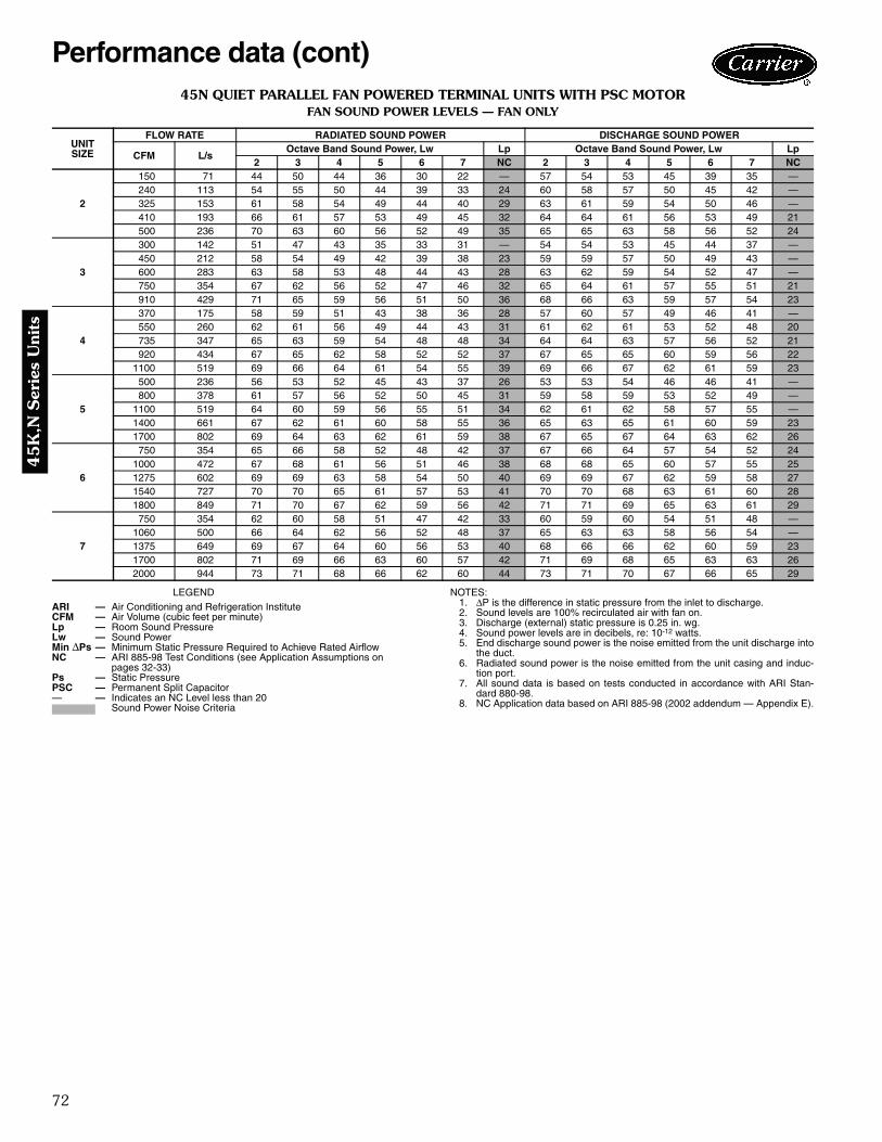
72
45
K,N
Ser
ies
Uni
ts
45N QUIET PARALLEL FAN POWERED TERMINAL UNITS WITH PSC MOTORFAN SOUND POWER LEVELS — FAN ONLY
LEGEND NOTES:1. ΔP is the difference in static pressure from the inlet to discharge.2. Sound levels are 100% recirculated air with fan on.3. Discharge (external) static pressure is 0.25 in. wg.4. Sound power levels are in decibels, re: 10-12 watts.5. End discharge sound power is the noise emitted from the unit discharge into
the duct.6. Radiated sound power is the noise emitted from the unit casing and induc-
tion port.7. All sound data is based on tests conducted in accordance with ARI Stan-
dard 880-98.8. NC Application data based on ARI 885-98 (2002 addendum — Appendix E).
UNITSIZE
FLOW RATE RADIATED SOUND POWER DISCHARGE SOUND POWER
CFM L/sOctave Band Sound Power, Lw Lp Octave Band Sound Power, Lw Lp
2 3 4 5 6 7 NC 2 3 4 5 6 7 NC
2
150 71 44 50 44 36 30 22 — 57 54 53 45 39 35 —240 113 54 55 50 44 39 33 24 60 58 57 50 45 42 —325 153 61 58 54 49 44 40 29 63 61 59 54 50 46 —410 193 66 61 57 53 49 45 32 64 64 61 56 53 49 21500 236 70 63 60 56 52 49 35 65 65 63 58 56 52 24
3
300 142 51 47 43 35 33 31 — 54 54 53 45 44 37 —450 212 58 54 49 42 39 38 23 59 59 57 50 49 43 —600 283 63 58 53 48 44 43 28 63 62 59 54 52 47 —750 354 67 62 56 52 47 46 32 65 64 61 57 55 51 21910 429 71 65 59 56 51 50 36 68 66 63 59 57 54 23
4
370 175 58 59 51 43 38 36 28 57 60 57 49 46 41 —550 260 62 61 56 49 44 43 31 61 62 61 53 52 48 20735 347 65 63 59 54 48 48 34 64 64 63 57 56 52 21920 434 67 65 62 58 52 52 37 67 65 65 60 59 56 22
1100 519 69 66 64 61 54 55 39 69 66 67 62 61 59 23
5
500 236 56 53 52 45 43 37 26 53 53 54 46 46 41 —800 378 61 57 56 52 50 45 31 59 58 59 53 52 49 —
1100 519 64 60 59 56 55 51 34 62 61 62 58 57 55 —1400 661 67 62 61 60 58 55 36 65 63 65 61 60 59 231700 802 69 64 63 62 61 59 38 67 65 67 64 63 62 26
6
750 354 65 66 58 52 48 42 37 67 66 64 57 54 52 241000 472 67 68 61 56 51 46 38 68 68 65 60 57 55 251275 602 69 69 63 58 54 50 40 69 69 67 62 59 58 271540 727 70 70 65 61 57 53 41 70 70 68 63 61 60 281800 849 71 70 67 62 59 56 42 71 71 69 65 63 61 29
7
750 354 62 60 58 51 47 42 33 60 59 60 54 51 48 —1060 500 66 64 62 56 52 48 37 65 63 63 58 56 54 —1375 649 69 67 64 60 56 53 40 68 66 66 62 60 59 231700 802 71 69 66 63 60 57 42 71 69 68 65 63 63 262000 944 73 71 68 66 62 60 44 73 71 70 67 66 65 29
ARI — Air Conditioning and Refrigeration InstituteCFM — Air Volume (cubic feet per minute)Lp — Room Sound PressureLw — Sound PowerMin ΔPs — Minimum Static Pressure Required to Achieve Rated AirflowNC — ARI 885-98 Test Conditions (see Application Assumptions on
pages 32-33)Ps — Static PressurePSC — Permanent Split Capacitor— — Indicates an NC Level less than 20
Sound Power Noise Criteria
Performance data (cont)

73
45K
,N S
eries Units
45N QUIET PARALLEL FAN POWERED TERMINAL UNITS WITH ECM OPTIONFAN SOUND POWER LEVELS — FAN ONLY
LEGEND NOTES:1. ΔP is the difference in static pressure from the inlet to discharge.2. Sound levels are 100% recirculated air with fan on.3. Discharge (external) static pressure is 0.25 in. wg.4. Sound power levels are in decibels, re: 10-12 watts.5. End discharge sound power is the noise emitted from the unit discharge into
the duct.6. Radiated sound power is the noise emitted from the unit casing and induc-
tion port.7. All sound data is based on tests conducted in accordance with ARI Stan-
dard 880-98.8. NC Application data based on ARI 885-98 (2002 addendum — Appendix E).
UNITSIZE
FLOW RATE RADIATED SOUND POWER DISCHARGE SOUND POWER
CFM L/sOctave Band Sound Power, Lw Lp Octave Band Sound Power, Lw Lp
2 3 4 5 6 7 NC 2 3 4 5 6 7 NC
4
400 189 59 59 52 44 39 38 28 58 61 58 50 47 42 —525 248 61 61 55 48 43 42 31 61 62 60 53 51 47 21650 307 64 62 58 52 46 46 33 63 63 62 55 54 50 21775 366 65 64 60 55 49 49 35 65 64 64 58 56 53 22900 425 67 65 61 57 51 51 37 66 65 65 59 58 56 23
7
800 378 63 60 59 52 48 43 34 61 60 60 55 52 49 —1100 519 67 64 62 57 53 49 37 65 63 63 59 57 55 211400 661 69 67 64 60 57 54 40 68 66 66 62 60 59 251700 802 71 69 66 63 60 57 42 71 69 68 65 63 63 262000 944 73 71 68 66 62 60 44 73 71 70 67 66 65 29
ARI — Air Conditioning and Refrigeration InstituteCFM — Air Volume (cubic feet per minute)ECM — Electrically Commutated MotorLp — Room Sound PressureLw — Sound PowerMin ΔPs — Minimum Static Pressure Required to Achieve Rated AirflowNC — ARI 885-98 Test Conditions (see Application Assumptions on
pages 32-33)Ps — Static Pressure— — Indicates an NC Level less than 20
Sound Power Noise Criteria
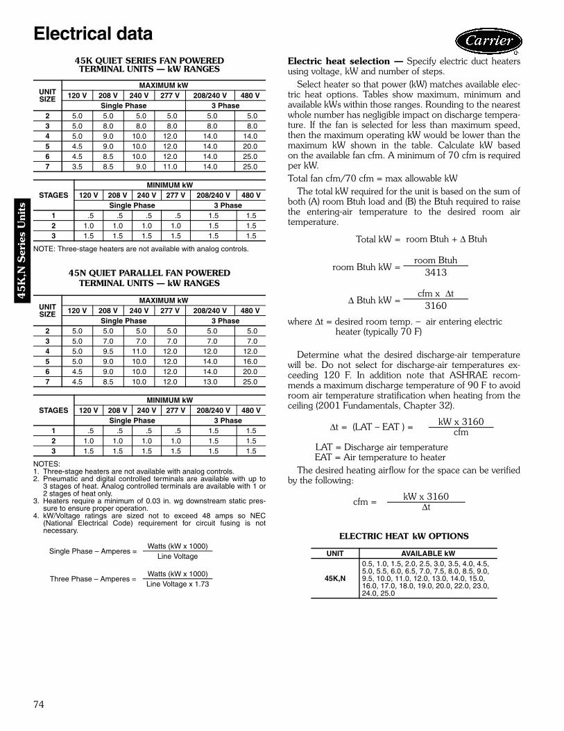
74
45
K,N
Ser
ies
Uni
ts
45K QUIET SERIES FAN POWEREDTERMINAL UNITS — kW RANGES
NOTE: Three-stage heaters are not available with analog controls.
45N QUIET PARALLEL FAN POWEREDTERMINAL UNITS — kW RANGES
NOTES: 1. Three-stage heaters are not available with analog controls.2. Pneumatic and digital controlled terminals are available with up to
3 stages of heat. Analog controlled terminals are available with 1 or2 stages of heat only.
3. Heaters require a minimum of 0.03 in. wg downstream static pres-sure to ensure proper operation.
4. kW/Voltage ratings are sized not to exceed 48 amps so NEC(National Electrical Code) requirement for circuit fusing is notnecessary.
Electric heat selection — Specify electric duct heatersusing voltage, kW and number of steps.
Select heater so that power (kW) matches available elec-tric heat options. Tables show maximum, minimum andavailable kWs within those ranges. Rounding to the nearestwhole number has negligible impact on discharge tempera-ture. If the fan is selected for less than maximum speed,then the maximum operating kW would be lower than themaximum kW shown in the table. Calculate kW basedon the available fan cfm. A minimum of 70 cfm is requiredper kW.Total fan cfm/70 cfm = max allowable kW
The total kW required for the unit is based on the sum ofboth (A) room Btuh load and (B) the Btuh required to raisethe entering-air temperature to the desired room airtemperature.
where Δt = desired room temp. – air entering electricheater (typically 70 F)
Determine what the desired discharge-air temperaturewill be. Do not select for discharge-air temperatures ex-ceeding 120 F. In addition note that ASHRAE recom-mends a maximum discharge temperature of 90 F to avoidroom air temperature stratification when heating from theceiling (2001 Fundamentals, Chapter 32).
LAT = Discharge air temperature EAT = Air temperature to heater
The desired heating airflow for the space can be verifiedby the following:
ELECTRIC HEAT kW OPTIONS
UNITSIZE
MAXIMUM kW120 V 208 V 240 V 277 V 208/240 V 480 V
Single Phase 3 Phase2 5.0 5.0 5.0 5.0 5.0 5.03 5.0 8.0 8.0 8.0 8.0 8.04 5.0 9.0 10.0 12.0 14.0 14.05 4.5 9.0 10.0 12.0 14.0 20.06 4.5 8.5 10.0 12.0 14.0 25.07 3.5 8.5 9.0 11.0 14.0 25.0
STAGESMINIMUM kW
120 V 208 V 240 V 277 V 208/240 V 480 VSingle Phase 3 Phase
1 .5 .5 .5 .5 1.5 1.52 1.0 1.0 1.0 1.0 1.5 1.53 1.5 1.5 1.5 1.5 1.5 1.5
UNITSIZE
MAXIMUM kW120 V 208 V 240 V 277 V 208/240 V 480 V
Single Phase 3 Phase2 5.0 5.0 5.0 5.0 5.0 5.03 5.0 7.0 7.0 7.0 7.0 7.04 5.0 9.5 11.0 12.0 12.0 12.05 5.0 9.0 10.0 12.0 14.0 16.06 4.5 9.0 10.0 12.0 14.0 20.07 4.5 8.5 10.0 12.0 13.0 25.0
STAGESMINIMUM kW
120 V 208 V 240 V 277 V 208/240 V 480 VSingle Phase 3 Phase
1 .5 .5 .5 .5 1.5 1.52 1.0 1.0 1.0 1.0 1.5 1.53 1.5 1.5 1.5 1.5 1.5 1.5
Single Phase – Amperes =Watts (kW x 1000)
Line Voltage
Three Phase – Amperes =Watts (kW x 1000)Line Voltage x 1.73
Total kW = room Btuh + Δ Btuh
room Btuh kW =room Btuh
3413
Δ Btuh kW =cfm x Δt
3160
Δt = (LAT – EAT ) = kW x 3160cfm
cfm = kW x 3160Δt
UNIT AVAILABLE kW
45K,N
0.5, 1.0, 1.5, 2.0, 2.5, 3.0, 3.5, 4.0, 4.5, 5.0, 5.5, 6.0, 6.5, 7.0, 7.5, 8.0, 8.5, 9.0, 9.5, 10.0, 11.0, 12.0, 13.0, 14.0, 15.0, 16.0, 17.0, 18.0, 19.0, 20.0, 22.0, 23.0, 24.0, 25.0
Electrical data
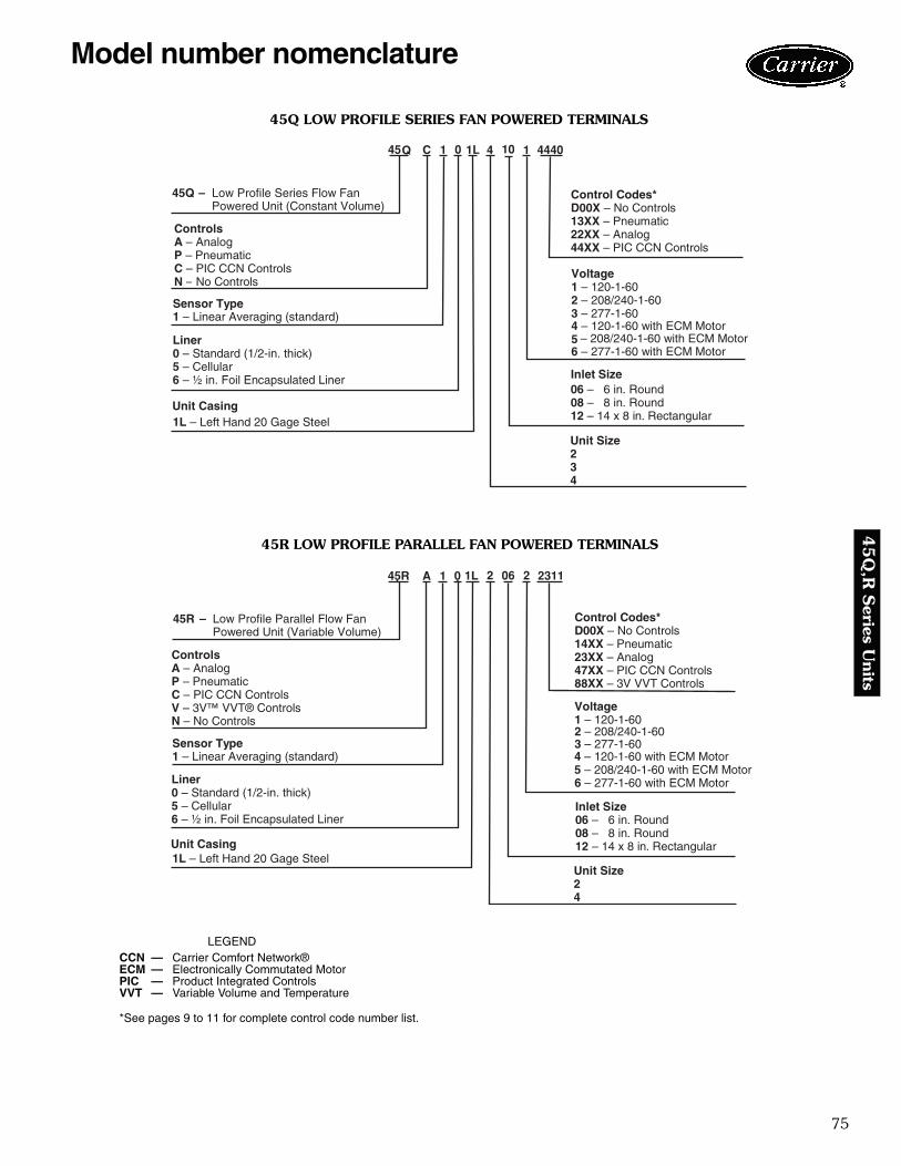
75
45
Q,R
Series U
nits
45Q – Low Profile Series Flow FanPowered Unit (Constant Volume)
Sensor Type1 – Linear Averaging (standard)
Liner0 – Standard (1/2-in. thick)5 – Cellular6 – ½ in. Foil Encapsulated Liner
Controls A – AnalogP – PneumaticC – PIC CCN ControlsN – No Controls
Unit Casing
Inlet Size
Control Codes* D00X – No Controls13XX – Pneumatic22XX – Analog44XX – PIC CCN Controls
Unit Size234
Voltage1 – 120-1-602 – 208/240-1-603 – 277-1-60
6 – 277-1-60 with ECM Motor
Q
45 – 208/240-1-60 with ECM Motor
– 120-1-60 with ECM Motor
1L – Left Hand 20 Gage Steel
06 – 6 in. Round08 – 8 in. Round12 – 14 x 8 in. Rectangular
C
45R – Low Profile Parallel Flow FanPowered Unit (Variable Volume)
Sensor Type 1 – Linear Averaging (standard)
Liner 0 – Standard (1/2-in. thick)5 – Cellular6 – ½ in. Foil Encapsulated Liner
Controls A – AnalogP – PneumaticC – PIC CCN ControlsV – 3V™ VVT® ControlsN – No Controls
Unit Casing1L – Left Hand 20 Gage Steel
Inlet Size06 – 6 in. Round08 – 8 in. Round12 – 14 x 8 in. Rectangular
Control Codes* D00X – No Controls14XX – Pneumatic23XX – Analog47XX – PIC CCN Controls88XX – 3V VVT Controls
Unit Size24
Voltage 1 – 120-1-602 – 208/240-1-603 – 277-1-60
6 – 277-1-60 with ECM Motor
45R
4 – 120-1-60 with ECM Motor5 – 208/240-1-60 with ECM Motor
1L0 2
LEGEND
*See pages 9 to 11 for complete control code number list.
CCN — Carrier Comfort Network®ECM — Electronically Commutated MotorPIC — Product Integrated ControlsVVT — Variable Volume and Temperature
a45-497
a45-498
45R LOW PROFILE PARALLEL FAN POWERED TERMINALS
45Q LOW PROFILE SERIES FAN POWERED TERMINALS
Model number nomenclature

76
45
Q,R
Ser
ies
Uni
ts
45Q LOW PROFILE SERIES FAN POWERED TERMINAL UNIT WEIGHTS (lb)
45R LOW PROFILE PARALLEL FAN POWERED TERMINAL UNIT WEIGHTS (lb)
DDC — Direct Digital Controls
FILTER SIZES
Size Base Unit With PneumaticControls
With DDC orAnalog Controls With Electric Heat With Hot Water Coils
(1 Row/2 Row)2 60 64 69 75 70/ 723 70 74 79 85 80/ 824 110 114 119 132 122/124
Size Base Unit With PneumaticControls
With DDC orAnalog Controls With Electric Heat With Hot Water Coils
(1 Row/2 Row)2 80 84 89 95 88/ 904 90 94 99 110 98/100
UNIT SIZE FILTER SIZE (in.)45Q Sizes 2, 3 15 x 10
45Q Size 4 (2) 12 x 10
45R All 18 x 10
522
2066
100
1000
10000
10
CFM
CFM
@
One
Inch
Signal
927
45QInlet Probe CMF vs Signal Graph
0.01 0.02 0.04 0.06 0.1 0.2 0.3 0.4 0.80.6 1.0 1
0.0 1.2 1.8 2.3 3.4 4.6 5.8 6.8 8.2 9.7 11
Inlet Size 8 in. x 14 in.
Inlet Size 8 in.
Inlet Size 6 in.
Pressure Differential in. wgVolts, Analog Controls
522
2066
100
1000
10000
10
CFM
CFM
@
One
Inch
Signal
927
45RInlet Probe CMF vs Signal Graph
0.01 0.02 0.04 0.06 0.1 0.2 0.3 0.4 0.80.6 1.0 1
0.0 1.2 1.8 2.3 3.4 4.6 5.8 6.8 8.2 9.7 11
Inlet Size 8 in. x 14 in.
Inlet Size 8 in.
Inlet Size 6 in.
Pressure Differential in. wgVolts, Analog Controls
45Q LOW PROFILE SERIES FAN POWEREDTERMINAL UNIT — LINEAR PROBE
CFM VS. SIGNAL GRAPH
45R LOW PROFILE PARALLEL FAN POWEREDTERMINAL UNIT — LINEAR PROBE
CFM VS. SIGNAL GRAPH
Physical data

77
45
Q,R
Series U
nits
PSC MOTOR (ECM MOTOROPTIONAL)
FORWARDCURVEDFAN
CONTROLENCLOSURE
PRIMARY INLET ANDLINEAR SENSOR
INDUCTIONPORT
ACCESSPANEL
FILTER(OPTIONAL)
FILTERCLIPS
ELECTRICHEATER
(OPTIONAL)
HOTWATER
COIL(OPTIONAL)
FORWARD CURVED FAN PSC MOTOR
BACKDRAFTDAMPER
CONTROLENCLOSURE
HOTWATER
COIL(OPTIONAL)
ELECTRICHEATER
(OPTIONAL)
FILTER(OPTIONAL)
ACCESS PANEL
PRIMARYINLET ANDLINEARSENSOR
FILTERCLIPS
INDUCTIONPORT
TYPICAL UNIT CONFIGURATION — 45Q LOW PROFILE SERIES FAN POWERED TERMINAL UNIT
TYPICAL UNIT CONFIGURATION — 45R LOW PROFILE PARALLEL FAN POWERED TERMINAL UNIT
LEGENDECM — Electronically Commutated MotorPSC — Permanent Split Capacitor
PSC — Permanent Split Capacitor
a45-499
a45-500

78
45
Q,R
Ser
ies
Uni
ts
INLET VIEW PLAN VIEW DISCHARGE VIEW
10 5/8"
14 5/8"
5 5/8"
5"
8 3/4"
34 1/8"
26"
6 3/8"
20"5/8"
3 7/8"
CONTROLSENCLOSURE
2 1/8"
9"
2 1/4"
10 5/8"
6 1/4"
INDUCEDAIR INLET
PRIMARYAIR INLET6Ó OR 8 ”
NOMINALSIZES
PRIMARYAIR INLET
DISCHARGE VIEWPLAN VIEWINLET VIEW
7 7/8"
13 1/2”
11"
8 3/4"
10 5/8"
INDUCEDAIR INLET
INDUCEDAIR INLET
34 1/8"
43"
6 3/8"
20"5/8"
3 7/8”
CONTROLSENCLOSURE
20 1/2"
10 5/8"
2 1/8"
11 1/4"
6 1/4"
45Q — LOW PROFILE SERIES FAN POWERED TERMINAL UNIT COOLING ONLYWITH ELECTRONIC CONTROLS, SIZES 2 AND 3
45Q — LOW PROFILE SERIES FAN POWERED TERMINAL UNIT COOLING ONLYWITH ELECTRONIC CONTROLS, SIZE 4
Dimensions

79
45
Q,R
Series U
nits
INLET VIEW PLAN VIEW DISCHARGE VIEW
14 5/8"
8 3/4"
5 1/2"
10 5/8"
5"
INDUCEDAIR INLET
34 1/8"
26"
31"
3 7/8”
6 1/4"
9 3/4"
CONTROLSENCLOSURE
ELECTRICHEATER
10 1/2"
TYPFLANGE
1"
8 3/8"
PRIMARYAIR INLET6” OR 8”
NOMINALSIZES
5/8"
26"
INLET VIEW PLAN VIEW DISCHARGE VIEW
7 7/8"13 1/2”
8 3/4"
10 5/8"
11”
INDUCEDAIR INLET
PRIMARYAIR INLET
INDUCEDAIR INLET 34 1/8"
43"
6 3/8"
5/8"
3 7/8”
9 3/4"
31" CONTROLSENCLOSURE
ELECTRICHEATER
8 1/2"
11 1/4"
20 1/2"
TYPFLANGE
1"
43"
45Q — LOW PROFILE SERIES FAN POWERED TERMINAL UNITWITH ELECTRIC HEAT AND ELECTRONIC CONTROLS, SIZES 2 AND 3
45Q — LOW PROFILE SERIES FAN POWERED TERMINAL UNITWITH ELECTRIC HEAT AND ELECTRONIC CONTROLS, SIZE 4

80
45
Q,R
Ser
ies
Uni
ts
INLET VIEW DISCHARGE VIEW
14 5/8"
8 3/4"
5 1/2"
10 5/8"
5"
INDUCEDAIR INLET
34 1/8" 9 3/8”
26"
6 3/8"
20"5/8"
3 7/8”
CONTROLSENCLOSURE
UNINSULATEDHOT WATERCOIL CASING
21 1/8"
FLANGETYP
7/8"2 1/8”
8 5/8"
PRIMARYAIR INLET6” OR 8”
NOMINALSIZES
21 1/8”
PLAN VIEW
PLAN VIEW DISCHARGE VIEWINLET VIEW
7 7/8"13 1/2”
8 3/4"
10 5/8"
11"
INDUCEDAIR INLET
PRIMARYAIR INLET
INDUCEDAIR INET
34 1/8" 9 3/8"
43"
6 3/8"
20"5/8"
3 7/8”
UNINSULATEDHOT WATERCOIL CASING
CONTROLSENCLOSURE
28 1/8"
8 5/8"
FLANGETYP
7/8"
7 1/2"
43"28 1/8"
45Q — LOW PROFILE SERIES FAN POWERED TERMINAL UNITWITH HOT WATER HEAT AND ELECTRONIC CONTROLS, SIZES 2 AND 3
45Q — LOW PROFILE SERIES FAN POWERED TERMINAL UNITWITH HOT WATER HEAT AND ELECTRONIC CONTROLS, SIZE 4
Dimensions (cont)

81
45
Q,R
Series U
nits
9 1/2"(241)
1 23/32" (44)DISCHARGE
3" (76)
FIN DEPTH1 3/32" (27)
2 9/32"(58)
MOUNTING HOLES ONTHIS FLANGE SIDE ONLY
1 ROW HOT WATER COILPLAN VIEW
9 1/2"(241)
1 23/32" (44)DISCHARGE
3" (76)
2 9/32"(58)
MOUNTING HOLES ONTHIS FLANGE SIDE ONLY
FIN DEPTH2 5/32" (55)
2 ROW HOT WATER COILPLAN VIEW
7/8" (22)
10 1/2"(267)
8 3/4"(222)
FINHEIGHT
FIN LENGTH
W PLUS 2" (51)
W
1 1/4"(32)
6 1/4"(159)
2 CONNECTIONS1/2" (13) O. D.1"
(25)
FRONT VIEW
RETURNCONNECTION
SUPPLYCONNECTION
HOT WATER HEAT COIL FOR 45Q LOW PROFILE SERIES FAN POWERED TERMINAL UNITS — SIZES 2-4
NOTE: Dimensions are given in inches. Dimensions in () are in millimeters.
UNITSIZE
DIMENSION (in.)W
221
34 28
a45-501

82
45
Q,R
Ser
ies
Uni
ts
RY
INDUCEDAIR INLET
5"
16 1/2"
8 1/2"
5 1/4"
10 5/8"
INLET VIEW
34 1/8"
30 1/8"
5/8"
3 7/8”
6 3/8"
20"
PLAN VIEW
CONTROLSENCLOSURE
10"
7 7/8"1 3/8"
1 1/2"
DISCHARGE VIEW
PRIMARYAIR INLET6” OR 8”
NOMINALSIZES
16 1/2"
13 1/2”
8 5/8"
16 1/2"
2 1/4”
7 7/8"
10 5/8"
INLET VIEW
INDUCEDAIR INLET
6 3/8"
5/8" 20 1/8”
36 1/8"
34 1/8"
3 7/8”
PLAN VIEW
CONTROLSENCLOSURE
15 7/8"
7 7/8"
1 3/8”
1 3/8"
DISCHARGE VIEW
PRIMARYAIR INLET
5/8”
16 1/2”
45R — LOW PROFILE PARALLEL FAN POWERED TERMINAL UNITCOOLING ONLY WITH ELECTRONIC CONTROLS, SIZE 2
45R — LOW PROFILE PARALLEL FAN POWERED TERMINAL UNITCOOLING ONLY WITH ELECTRONIC CONTROLS, SIZE 4
Dimensions (cont)

83
45
Q,R
Series U
nits
34 1/8"
30 1/8"
5/8"
3 7/8”
9 3/4"
31"
16 3/4"
6 3/8"
PLAN VIEW
CONTROLSENCLOSURE
ELECTRICHEATER
TYP1" FLANGE
10 1/2"
8 3/8"
DISCHARGE VIEW
INDUCEDAIR INLET
5"
16 1/2"
8 1/2"
5 1/4"
10 5/8"
PRIMARYAIR INLET6” OR 8”
NOMINALSIZES
INLET VIEW
5/8"
PRIMARYAIR INLET
INDUCEDAIR INLET
13 1/2"
8 5/8"
16 1/2"
7 7/8"
10 5/8"
INLET VIEW
5/8" 31"
36 1/8"
34 1/8"
3 7/8”
9 3/4"
6 3/8"
22 3/4"
PLAN VIEW
CONTROLSENCLOSURE
ELECTRICHEATER
16 1/2"
8 3/8"
TYP1" FLANGE
DISCHARGE VIEW
45R — LOW PROFILE PARALLEL FAN POWERED TERMINAL UNITWITH ELECTRIC HEAT AND ELECTRONIC CONTROLS, SIZE 2
45R — LOW PROFILE PARALLEL FAN POWERED TERMINAL UNITWITH ELECTRIC HEAT AND ELECTRONIC CONTROLS, SIZE 4

84
45
Q,R
Ser
ies
Uni
ts
INDUCEDAIR INLET
34 1/8"
30 1/8"
5/8"
3 7/8”
6 3/8"
20"
4 1/8"
CONTROLSENCLOSURE
10"
7 7/8"1 3/8"
1 1/2"
10 5/8"
5"
5 1/4"
10 1/4"
17 3/4"
HOTWATER
COIL
INLET VIEW PLAN VIEW DISCHARGE VIEW
PRIMARYAIR INLET6" OR 8"
NOMINALSIZES
3/4” FLANGE TYP
INLET VIEW PLAN VIEW DISCHARGE VIEW
13 1/2”7 7/8"
17 3/4"
10 1/4"TYP3/4" FLANGE
PRIMARYAIR INLET
INDUCEDAIR INLET
HOTWATER
COIL
6 3/8"
5/8" 20 1/8"
36 1/8"
34 1/8"
3 7/8”
4 1/8"
CONTROLSENCLOSURE
15 7/8"
7 7/8"
1 3/8"
1 3/8"
10 5/8"
5/8”
45R — LOW PROFILE PARALLEL FAN POWERED TERMINAL UNITWITH HOT WATER HEAT AND ELECTRONIC CONTROLS, SIZE 2
45R — LOW PROFILE PARALLEL FAN POWERED TERMINAL UNITWITH HOT WATER HEAT AND ELECTRONIC CONTROLS, SIZE 4
Dimensions (cont)

85
45
Q,R
Series U
nits
4 1/8"(105)
31/32" (18)DISCHARGE
3"(76)
1 1/2"(38)
FIN DEPTH1 3/32" (28)
MOUNTING HOLES ONTHIS FLANGE SIDE ONLY
1 ROW HOT WATER COILPLAN VIEW
4 1/8"(105)
31/32" (18)
DISCHARGE
3"(76)
1 1/2" (38)
FIN DEPTH2 5/32" (55)
MOUNTING HOLES ONTHIS FLANGE SIDE ONLY
2 19/32" (66)
2 ROW HOT WATER COILPLAN VIEW
23/32" (18)
10 1/4"(260)
8 27/32"(224)
16 3/8" (416)
17 13/16" (452)
2 11/32" (59)
6 1/4"(159)
23/32"(18)
FRONT VIEW
2 CONNECTIONS1/2" (13) O. D.
SUPPLYCONNECTION
RETURNCONNECTION
HOT WATER HEAT COIL FOR 45R LOW PROFILE PARALLEL FAN POWERED TERMINAL UNITS — SIZES 2 AND 4
NOTE: Dimensions are given in inches. Dimensions in () are in millimeters.
a45-502

86
45
Q,R
Ser
ies
Uni
ts
45Q LOW PROFILE SERIES FAN POWERED TERMINAL UNITS
45R LOW PROFILE PARALLEL FAN POWERED TERMINAL UNITS
LEGEND
NOTES:1. 45Q maximum primary airflow (cfm) is set by the maximum induced
airflow, which may vary as a function of downstream pressure. Maxi-mum airflow shown is based on the maximum induced airflow (Fan air-flow) or 1.00 in. wg velocity pressure at inlet probe, whichever is less.
2. 45R maximum primary airflow (cfm) is based on 1.00 in. wg velocitypressure signal (VP), per inlet size, using a standard linear averagingsensor.
3. Minimum recommended primary airflow (cfm) is based on 0.03 in. wgdifferential pressure of the linear inlet flow sensor, or 0 airflow.0.03 in. wg is equal to 15% to 20% of the nominal flow rating of the ter-minal. Less than 15% to 20% may result in greater than +5% control ofbox flow.
4. 45R maximum fan airflow (cfm) is based on 0.25 in. wg external(Downstream) static pressure, and 45Q Maximum Fan airflow is basedon 0.10 in. wg downstream static pressure (See page 16 for completefan curves).
5. 45Q or 45R minimum fan airflow (cfm) is based on maximum external(downstream) static pressure 0.60 in. wg.
6. Minimum primary airflow (cfm) listed is for all controls except CCNwhich is shown separately with lower available minimum CFMs. SomeDDC controls supplied by others may have different limitations.
7. Minimum pressure, Ps (in. wg) on 45R water coil units is based on coillocated on induction port.
8. Do not select discharge temperature exceeding 120 F. In addition,ASHRAE recommends a maximum discharge temperature of 90 F toavoid room air stratification when heating from the ceiling (2001 Funda-mentals, Chapter 32).
ARI CERTIFICATION RATING POINTS45Q LOW PROFILE SERIES FAN POWERED TERMINAL UNITS — DISCHARGE
45Q LOW PROFILE SERIES FAN POWERED TERMINAL UNITS — RADIATED
45R LOW PROFILE PARALLEL FAN POWEREDTERMINAL UNITS — DISCHARGE
45R LOW PROFILE PARALLEL FAN POWEREDTERMINAL UNITS — RADIATED
45R LOW PROFILE PARALLEL FAN POWERED TERMINAL UNITS — FAN ONLY
LEGEND
UNITSIZE45Q
INLETSIZE (in.)
MOTORHP
MOTOR AMPS FAN AIRFLOW (cfm) PRIMARY AIRFLOW (cfm) MINIMUMPs. (in. wg)120V 208/230V 277V Max Min Max Min Min CCN
26 1/6 2.8 1.5 1.1 840 310 522 90 52 0.04
8 1/6 2.8 1.5 1.1 840 310 840 160 93 0.06
3 8 1/4 4.1 2.2 1.6 1090 520 927 160 93 0.07
4 8 x 14 (2) 1/6 6.9 3.7 2.7 1650 800 1650 358 207 0.10
UNITSIZE45R
INLETSIZE (in.)
MOTORHP
MOTOR AMPS FAN AIRFLOW (cfm) PRIMARY AIRFLOW (cfm) MINIMUM Ps (in. wg)
120V 208/230V 277V Max Min Max Min Min CCN None orElec. Heat
1 RowHot Water
2 RowsHot Water
26 1/6 2.8 1.5 1.0 620 250 522 90 52 0.10 0.10 0.10
8 1/6 2.8 1.5 1.0 620 250 927 160 93 0.18 0.18 0.18
4 8 x 14 1/4 3.9 2.1 1.4 830 450 2066 358 207 0.17 0.17 0.17
CCN — Carrier Comfort NetworkDDC — Direct Digital ControlsPs — Static Pressure
UNITSIZE
FANCFM
FANWATTS
FAN ONLY SOUND POWER2 3 4 5 6 7
2 700 300 60 60 62 61 61 583 925 440 63 62 65 64 63 614 1400 750 75 61 62 60 60 58
UNITSIZE
INLETSIZE
PRIM.CFM
MINPs
FAN PLUS PRIMARY AT1.5 IN. WG INLET
2 3 4 5 6 72 8 700 0.08 67 66 62 60 54 503 8 925 0.07 74 73 68 65 59 534 8x14 1400 0.07 76 73 69 65 58 51
UNITSIZE
FANCFM
FANWATTS
FAN ONLY SOUND POWER
2 3 4 5 6 72 700 300 62 55 55 52 46 353 925 440 66 60 60 58 51 454 1400 750 65 61 61 60 52 44
UNITSIZE
INLETSIZE
PRIM.CFM
MINΔ Ps
SOUND POWER AT 1.5 IN. WG Δ Ps2 3 4 5 6 7
2 8 700 0.059 67 68 63 58 54 494 8x14 1575 0.076 72 71 70 65 63 56
UNITSIZE
INLETSIZE
PRIM.CFM
MINΔ Ps
SOUND POWER AT 1.5 IN. WG Δ Ps2 3 4 5 6 7
2 8 700 0.059 64 62 59 56 53 484 8x14 1575 0.076 70 66 63 55 51 46
UNITSIZE
FANCFM
FANWATTS
RADIATED SOUND POWER DISCHARGE SOUND POWERFan Only Fan Only
2 3 4 5 6 7 2 3 4 5 6 72 600 275 63 60 60 57 50 39 61 57 59 57 50 494 800 385 64 65 65 62 56 47 61 59 63 60 54 53
Ps — Static PressureΔPs — Difference in static pressure from the inlet to the discharge
Performance data
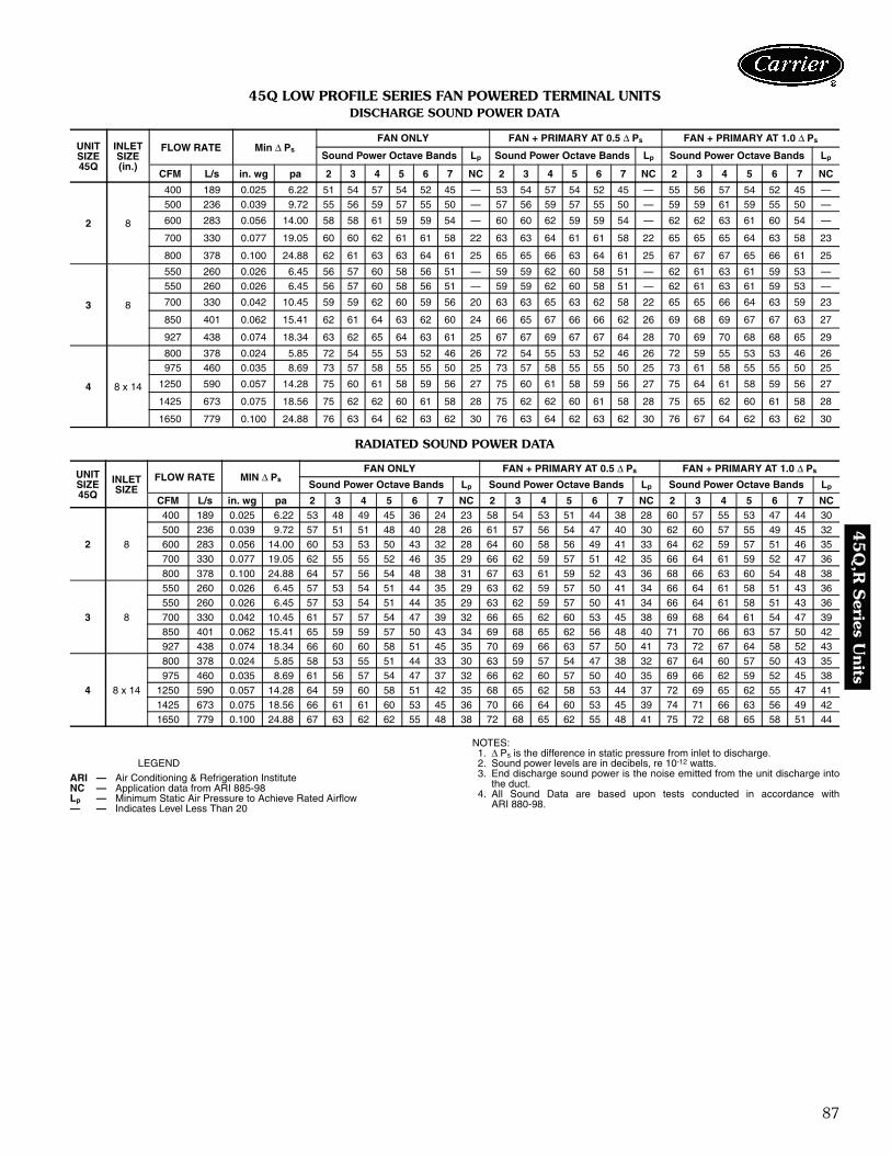
87
45
Q,R
Series U
nits
45Q LOW PROFILE SERIES FAN POWERED TERMINAL UNITSDISCHARGE SOUND POWER DATA
RADIATED SOUND POWER DATA
LEGEND
NOTES:1. Δ Ps is the difference in static pressure from inlet to discharge.2. Sound power levels are in decibels, re 10-12 watts.3. End discharge sound power is the noise emitted from the unit discharge into
the duct.4. All Sound Data are based upon tests conducted in accordance with
ARI 880-98.
UNIT SIZE45Q
INLETSIZE(in.)
FLOW RATE Min Δ PsFAN ONLY FAN + PRIMARY AT 0.5 Δ Ps FAN + PRIMARY AT 1.0 Δ Ps
Sound Power Octave Bands Lp Sound Power Octave Bands Lp Sound Power Octave Bands Lp
CFM L/s in. wg pa 2 3 4 5 6 7 NC 2 3 4 5 6 7 NC 2 3 4 5 6 7 NC
2 8
400 189 0.025 6.22 51 54 57 54 52 45 — 53 54 57 54 52 45 — 55 56 57 54 52 45 —500 236 0.039 9.72 55 56 59 57 55 50 — 57 56 59 57 55 50 — 59 59 61 59 55 50 —
600 283 0.056 14.00 58 58 61 59 59 54 — 60 60 62 59 59 54 — 62 62 63 61 60 54 —
700 330 0.077 19.05 60 60 62 61 61 58 22 63 63 64 61 61 58 22 65 65 65 64 63 58 23
800 378 0.100 24.88 62 61 63 63 64 61 25 65 65 66 63 64 61 25 67 67 67 65 66 61 25
3 8
550 260 0.026 6.45 56 57 60 58 56 51 — 59 59 62 60 58 51 — 62 61 63 61 59 53 —550 260 0.026 6.45 56 57 60 58 56 51 — 59 59 62 60 58 51 — 62 61 63 61 59 53 —
700 330 0.042 10.45 59 59 62 60 59 56 20 63 63 65 63 62 58 22 65 65 66 64 63 59 23
850 401 0.062 15.41 62 61 64 63 62 60 24 66 65 67 66 66 62 26 69 68 69 67 67 63 27
927 438 0.074 18.34 63 62 65 64 63 61 25 67 67 69 67 67 64 28 70 69 70 68 68 65 29
4 8 x 14
800 378 0.024 5.85 72 54 55 53 52 46 26 72 54 55 53 52 46 26 72 59 55 53 53 46 26975 460 0.035 8.69 73 57 58 55 55 50 25 73 57 58 55 55 50 25 73 61 58 55 55 50 25
1250 590 0.057 14.28 75 60 61 58 59 56 27 75 60 61 58 59 56 27 75 64 61 58 59 56 27
1425 673 0.075 18.56 75 62 62 60 61 58 28 75 62 62 60 61 58 28 75 65 62 60 61 58 28
1650 779 0.100 24.88 76 63 64 62 63 62 30 76 63 64 62 63 62 30 76 67 64 62 63 62 30
UNITSIZE45Q
INLETSIZE
FLOW RATE MIN Δ PsFAN ONLY FAN + PRIMARY AT 0.5 Δ Ps FAN + PRIMARY AT 1.0 Δ Ps
Sound Power Octave Bands Lp Sound Power Octave Bands Lp Sound Power Octave Bands Lp
CFM L/s in. wg pa 2 3 4 5 6 7 NC 2 3 4 5 6 7 NC 2 3 4 5 6 7 NC
2 8
400 189 0.025 6.22 53 48 49 45 36 24 23 58 54 53 51 44 38 28 60 57 55 53 47 44 30500 236 0.039 9.72 57 51 51 48 40 28 26 61 57 56 54 47 40 30 62 60 57 55 49 45 32600 283 0.056 14.00 60 53 53 50 43 32 28 64 60 58 56 49 41 33 64 62 59 57 51 46 35700 330 0.077 19.05 62 55 55 52 46 35 29 66 62 59 57 51 42 35 66 64 61 59 52 47 36800 378 0.100 24.88 64 57 56 54 48 38 31 67 63 61 59 52 43 36 68 66 63 60 54 48 38
3 8
550 260 0.026 6.45 57 53 54 51 44 35 29 63 62 59 57 50 41 34 66 64 61 58 51 43 36550 260 0.026 6.45 57 53 54 51 44 35 29 63 62 59 57 50 41 34 66 64 61 58 51 43 36700 330 0.042 10.45 61 57 57 54 47 39 32 66 65 62 60 53 45 38 69 68 64 61 54 47 39850 401 0.062 15.41 65 59 59 57 50 43 34 69 68 65 62 56 48 40 71 70 66 63 57 50 42927 438 0.074 18.34 66 60 60 58 51 45 35 70 69 66 63 57 50 41 73 72 67 64 58 52 43
4 8 x 14
800 378 0.024 5.85 58 53 55 51 44 33 30 63 59 57 54 47 38 32 67 64 60 57 50 43 35975 460 0.035 8.69 61 56 57 54 47 37 32 66 62 60 57 50 40 35 69 66 62 59 52 45 38
1250 590 0.057 14.28 64 59 60 58 51 42 35 68 65 62 58 53 44 37 72 69 65 62 55 47 411425 673 0.075 18.56 66 61 61 60 53 45 36 70 66 64 60 53 45 39 74 71 66 63 56 49 421650 779 0.100 24.88 67 63 62 62 55 48 38 72 68 65 62 55 48 41 75 72 68 65 58 51 44
ARI — Air Conditioning & Refrigeration InstituteNC — Application data from ARI 885-98Lp — Minimum Static Air Pressure to Achieve Rated Airflow— — Indicates Level Less Than 20

88
45
Q,R
Ser
ies
Uni
ts
45R LOW PROFILE PARALLEL FAN POWERED TERMINAL UNITSPRIMARY DISCHARGE SOUND POWER LEVELS — 100% PRIMARY AIR
PRIMARY RADIATED SOUND POWER LEVELS — 100% PRIMARY AIR
FAN SOUND POWER LEVELS — FAN ONLY
LEGEND NOTES:1. Δ Ps is the difference in static pressure from the terminal discharge to the
room.2. Radiated sound power is the noise transmitted through the casing walls.3. Discharge sound power is the noise emitted from the unit discharge into the
downstream duct.4. All Sound Data are based upon tests conducted in accordance with
ARI 880-98.
UNITSIZE45R
INLETSIZE
FLOW RATE MIN Δ PsPRIMARY AT 0.5 Δ Ps PRIMARY AT 1.0 Δ Ps PRIMARY AT 2.0 Δ Ps
Sound Power Octave Bands Lp Sound Power Octave Bands Lp Sound Power Octave Bands Lp
CFM L/s in. wg pa 2 3 4 5 6 7 NC 2 3 4 5 6 7 NC 2 3 4 5 6 7 NC
2 6
150 71 0.008 2.1 43 44 42 37 28 17 — 46 46 45 40 30 21 — 49 49 49 43 33 25 —240 113 0.022 5.4 49 49 47 43 35 25 — 52 52 51 46 38 29 — 55 54 54 48 41 33 —325 153 0.040 9.9 52 53 51 46 40 31 — 56 55 54 49 43 35 — 59 58 58 52 45 39 —410 193 0.063 15.8 55 56 54 49 44 35 — 58 58 57 52 46 39 — 62 60 61 55 49 43 —500 236 0.094 23.5 58 58 56 51 47 38 — 61 60 59 54 50 42 — 64 63 63 57 52 46 20
2 8
300 142 0.011 2.7 50 46 49 44 39 29 — 55 51 53 48 42 33 — 59 57 57 52 44 37 —450 212 0.024 6.1 54 52 52 48 44 36 — 59 58 57 51 47 40 — 64 63 61 55 50 43 21600 283 0.043 10.8 58 56 55 50 48 40 — 63 62 59 54 51 44 — 68 68 63 58 54 48 26750 354 0.068 16.9 60 60 57 52 51 44 — 65 65 61 56 54 48 23 70 71 65 60 57 51 29910 429 0.100 24.9 63 63 59 54 53 47 — 68 69 63 58 56 51 26 73 74 67 61 59 54 33
4 8 x 14
800 378 0.020 4.9 56 54 53 48 44 35 — 61 60 59 53 50 42 — 66 65 65 59 56 49 221000 472 0.031 7.7 59 57 55 50 47 38 — 64 62 61 56 53 45 — 69 68 68 62 59 52 251250 590 0.048 12.0 61 59 58 53 50 42 — 66 65 64 59 56 49 22 71 71 70 64 62 56 291500 708 0.069 17.3 63 61 60 55 53 45 — 68 67 66 61 59 52 24 73 73 72 67 65 59 311800 849 0.100 24.9 65 64 62 57 55 48 20 70 69 68 63 61 55 27 75 75 74 69 67 61 34
UNITSIZE45R
INLETSIZE
FLOW RATE MIN Δ PsPRIMARY AT 0.5 Δ Ps PRIMARY AT 1.0 Δ Ps PRIMARY AT 2.0 Δ Ps
Sound Power Octave Bands Lp Sound Power Octave Bands Lp Sound Power Octave Bands Lp
CFM L/s in. wg pa 2 3 4 5 6 7 NC 2 3 4 5 6 7 NC 2 3 4 5 6 7 NC
2
6
150 71 0.008 2.1 44 43 40 36 35 29 — 46 44 43 38 36 32 — 47 46 45 40 38 35 —240 113 0.022 5.4 49 47 44 40 38 32 — 51 49 47 42 39 35 21 53 51 49 43 41 38 23325 153 0.040 9.9 53 50 47 43 40 34 21 55 52 49 44 41 37 23 56 54 52 46 43 40 26410 193 0.063 15.8 56 53 49 44 41 35 23 57 54 51 46 43 38 25 59 56 53 48 45 41 28500 236 0.094 23.5 58 54 50 46 43 36 24 60 56 53 47 44 39 27 61 58 55 49 46 42 30
8
300 142 0.011 2.7 44 43 41 38 32 26 — 51 49 45 41 36 31 — 58 54 49 45 40 37 23450 212 0.024 6.1 50 48 47 44 39 32 21 56 53 50 47 43 38 25 63 59 54 51 47 44 29600 283 0.043 10.8 53 51 51 48 44 37 25 60 56 54 52 48 43 29 67 62 58 55 52 48 33750 354 0.068 16.9 56 53 54 52 47 41 28 63 59 57 55 51 46 32 70 64 61 59 55 52 36910 429 0.100 24.9 59 55 56 54 50 44 31 66 61 60 58 54 49 35 72 66 64 62 58 55 39
4 8 x 14
800 378 0.020 4.9 56 54 50 43 37 31 24 62 60 55 46 41 36 29 68 66 59 50 44 40 361000 472 0.031 7.7 57 55 52 45 40 34 26 63 61 57 49 43 38 31 69 67 61 52 47 43 371250 590 0.048 12.0 59 56 54 47 43 36 28 65 62 59 51 46 41 34 71 67 63 54 49 46 391500 708 0.069 17.3 60 57 55 49 45 38 30 66 62 60 53 48 43 35 72 68 65 56 51 48 401800 849 0.100 24.9 61 57 57 51 47 41 32 67 63 62 55 50 45 37 73 69 67 58 54 50 42
UNITSIZE45R
FLOW RATERADIATED SOUND POWER Lw DISCHARGE SOUND POWER Lw
Octave Bands LP Octave Bands LP
CFM L/s 2 3 4 5 6 7 NC 2 3 4 5 6 7 NC
2
300 142 45 52 52 53 48 40 26 52 49 54 50 43 36 —
375 177 48 56 54 55 51 43 29 55 51 55 52 45 40 —
450 212 50 58 56 57 53 45 31 58 53 57 54 47 43 —
525 248 52 61 58 59 55 47 33 60 55 58 56 49 46 —
600 283 53 62 60 60 57 49 35 61 57 59 57 50 49 —
4
460 217 59 56 57 53 45 34 32 54 51 56 52 44 39 —
525 248 60 58 59 55 48 37 34 56 53 57 54 47 43 —
600 283 61 60 61 57 50 40 36 57 55 59 56 49 46 —
725 342 63 63 64 60 54 45 39 60 58 62 59 52 51 —
800 378 64 65 65 62 56 47 40 61 59 63 60 54 53 —
ARI — Air Conditioning & Refrigeration InstituteNC — Application data from ARI 885-98Lp — Minimum Static Air Pressure to Achieve Rated AirflowLw — Sound Power (dB)— — Indicates Level Less Than 20
Performance data (cont)

89
45
Q,R
Series U
nits
45Q LOW PROFILE SERIES AND 45R LOW PROFILE PARALLEL FAN POWERED TERMINAL UNITSAPPLICATION ASSUMPTIONS
NOTE: Ceiling type — Mineral Fiber, 5/8 in.-35 lb/cu. ft
Notes for Sound Data Tables:Both ARI and ASHRAE (American Society of Heating, Re-frigeration and Air Conditioning Engineers) provide guid-ance in both measuring sound power levels (per ARI 880-98), and in estimating the resultant room sound pressure,typically shown as an NC level (per ARI 885-98 — 2002addendum — Appendix E). The ASHRAE handbooks pro-vide detailed acoustical guidance. For applications, ARIStandard 885 is an application standard which provides ta-bles and equations for determining acoustical deduction
based on the ASHRAE guides, as well as additional infor-mation provided by manufacturers.All sound data shown by octave bands is raw data withoutany corrections for room absorption or duct attenuation.This sound power data is tested in accordance with ARIStandard 880-98.The NC values reflect a more accurate sound level estimatefor typical office spaces or other applications. These NClevels are calculated based on procedures from ARI Stan-dard 885-98.
ARI 885-98RADIATED
RADIATED SOUND APPLICATIONASSUMPTIONS (dB)
Octave Bands2 3 4 5 6 7
Environ. Effect 2 1 0 0 0 0Plenum/Room Effect 16 18 20 26 31 36Total Attenuation 18 19 20 26 31 36
ARI 885-98DISCHARGE < 300 cfm
DISCHARGE SOUND APPLICATIONASSUMPTIONS (dB)
Octave Bands2 3 4 5 6 7
Environ. Effect 2 1 0 0 0 0Duct Lining, 5-ft, 8x8x1-in. 2 6 12 25 29 18End Reflection 9 5 2 0 0 0Power Division (0 outlets) 0 0 0 0 0 05-ft, 8-in. Flex Duct 6 10 18 20 21 12Space Effect 5 6 7 8 9 10Total Attenuation 24 28 39 53 59 40
ARI 885-98DISCHARGE 300-700 cfm
DISCHARGE SOUNDAPPLICATION ASSUMPTIONS (dB)
Octave Bands2 3 4 5 6 7
Environ. Effect 2 1 0 0 0 0Duct Lining, 5-ft, 12x12x1-in. 2 4 10 20 20 1410 in. End Reflection 9 5 1 0 0 0Power Division (2 outlets) 3 3 3 3 3 35-ft, 8-in. Flex Duct 6 10 18 20 21 12Space Effect 5 6 7 8 9 10Total Attenuation 27 29 40 51 53 39
ARI 885-98DISCHARGE > 700 cfm
DISCHARGE SOUNDAPPLICATION ASSUMPTIONS (dB)
Octave Bands2 3 4 5 6 7
Environ. Effect 2 1 0 0 0 0Duct Lining, 5-ft, 15x15x1-in. 2 3 9 18 17 12End Reflection 9 5 2 0 0 0Power Division (3 outlets) 5 5 5 5 5 55-ft, 8-in. Flex Duct 6 10 18 20 21 12Space Effect 5 6 7 8 9 10Total Attenuation 29 30 41 51 52 39

90
45
Q,R
Ser
ies
Uni
ts
1200
1100
1000
900
800
700
600
500
4000.1 0.2 0.3 0.4 0.5 0.6STATIC PRESSURE - INCHES OF WATER
MAX MIN 1 ROW HW 2 ROW HWMAX MIN 1 ROW HW 2 ROW HW
STATIC PRESSURE - INCHES OF WATER
CF
M
CF
M
900
800
700
600
500
400
300
2000.1 0.2 0.3 0.4 0.5 0.6
SIZE 2 SIZE 3
1800
800
600
SIZE 4
1600
1400
1200
1000
0.1 0.2 0.3 0.4 0.5 0.6STATIC PRESSURE-INCHES OF WATER
CF
M
1 ROW HW 2 ROW HWMAX MIN
0
100
200
0.1 0.2 0.3 0.4 0.5 0.6
900
800
700
600
500
400
300
CF
M
UNIT SIZE 2
0
200
0.1 0.2 0.3 0.4 0.5 0.6
800
600
400
CF
M
UNIT SIZE 41000
STATIC PRESSURE-INCHES OF WATER
1 ROW HW 2 ROW HWMAX MIN
STATIC PRESSURE-INCHES OF WATER
1 ROW HW 2 ROW HWMAX MIN
45Q LOW PROFILE SERIES FAN POWERED TERMINAL UNITSAIRFLOW VS. DOWNSTREAM STATIC PRESSURE
45R LOW PROFILE PARALLEL FAN POWERED TERMINAL UNITSAIRFLOW VS. DOWNSTREAM STATIC PRESSURE
Performance data (cont)

91
45
Q,R
Series U
nits
45Q LOW PROFILE SERIES FAN POWERED TERMINAL UNITSWATER COIL PERFORMANCE DATA
NOTES:1. All data is based on: 65.0 F entering water, 180.0 F entering air, at an altitude
of 0 ft above sea level.2. Program calculations assume 0% glycol.3. Head loss is in feet of water.4. Coil performance is in MBtuh.5. Delta T = temperature rise across the coil.6. Refer to Carrier electronic selection program or table at right for correction
factors for other conditions.
CORRECTION FACTORS FOR OTHERENTERING CONDITIONS
45R LOW PROFILE PARALLEL FAN POWERED TERMINAL UNITSWATER COIL PERFORMANCE DATA
NOTES:1. All data is based on: 65.0 F entering water, 180.0 F entering air, at an altitude
of 0 ft above sea level.2. Program calculations assume 0% glycol.3. Head loss is in feet of water.4. Coil performance is in MBtuh.5. Delta T = temperature rise across the coil.6. Refer to Carrier electronic selection program or table at right for correction
factors for other conditions.
CORRECTION FACTORS FOR OTHERENTERING CONDITIONS
SIZE ROWS GPM HEAD LOSSAIR FLOW, CFM
400 450 500 550 600 650 700 750 800
2
One Row
1.0 0.20 12.8 13.4 14.1 14.6 15.1 15.6 16.1 16.5 16.92.0 0.50 14.4 15.3 16.1 16.9 17.6 18.2 18.9 19.4 20.04.0 1.80 15.5 16.5 17.5 18.4 19.2 20.0 20.8 21.5 22.26.0 3.80 15.9 17.0 18.0 19.0 19.9 20.7 21.6 22.3 23.1
Airside Δ Ps (in. wg) 0.03 0.04 0.05 0.06 0.07 0.08 0.09 0.10 0.11
Two Rows
1.0 0.40 22.0 23.2 24.3 25.2 26.1 26.9 27.6 28.3 28.93.0 2.50 27.0 29.0 30.8 32.5 34.0 35.5 36.9 38.2 39.45.0 6.10 28.3 30.5 32.5 34.4 36.2 37.9 39.5 41.0 42.57.0 11.10 28.9 31.2 33.3 35.4 37.3 39.1 40.8 42.4 44.0
Airside Δ Ps (in. wg) 0.06 0.08 0.09 0.11 0.13 0.15 0.17 0.19 0.22
SIZE ROWS GPM HEAD LOSSAIR FLOW, CFM
500 570 640 710 780 850 920 990 1060
3
One Row
1.0 0.20 14.1 14.8 15.5 16.1 16.7 17.2 17.7 18.1 18.52.0 0.50 16.1 17.2 18.1 19.0 19.8 20.5 21.2 21.9 22.54.0 1.80 17.5 18.7 19.9 20.9 21.9 22.8 23.7 24.5 25.36.0 3.80 18.0 19.4 20.6 21.7 22.8 23.8 24.7 25.6 26.4
Airside Δ Ps (in. wg) 0.05 0.06 0.08 0.09 0.11 0.13 0.15 0.17 0.19
Two Rows
1.0 0.40 24.3 25.6 26.7 27.7 28.6 29.4 30.2 30.8 31.43.0 2.50 30.8 33.1 35.2 37.2 39.0 40.6 42.1 43.6 44.95.0 6.10 32.5 35.2 37.6 39.8 41.9 43.9 45.7 47.5 49.17.0 11.10 33.3 36.1 38.7 41.1 43.4 45.5 47.5 49.3 51.1
Airside Δ Ps (in. wg) 0.09 0.12 0.14 0.17 0.21 0.24 0.28 0.31 0.35
SIZE ROWS GPM HEAD LOSSAIR FLOW, CFM
900 985 1070 1155 1240 1325 1410 1495 1580
4
One Row
1.0 0.20 20.2 20.8 21.4 22.0 22.5 22.9 23.4 23.8 24.12.0 0.60 24.2 25.1 26.0 26.8 27.6 28.3 29.0 29.7 30.34.0 2.10 26.9 28.1 29.2 30.3 31.3 32.2 33.1 34.0 34.86.0 4.20 28.0 29.3 30.5 31.7 32.8 33.8 34.8 35.8 36.7
Airside Δ Ps (in. wg) 0.08 0.10 0.11 0.13 0.15 0.17 0.18 0.20 0.23
Two Rows
1.0 0.40 33.4 34.3 35.2 35.9 36.6 37.2 37.8 38.3 38.73.0 2.80 46.9 49.0 50.9 52.7 54.4 56.0 57.5 58.9 60.25.0 6.80 50.7 53.3 55.6 57.9 60.0 61.9 63.8 65.6 67.37.0 12.40 52.6 55.4 57.9 60.4 62.7 64.9 66.9 68.9 70.8
Airside Δ Ps (in. wg) 0.16 0.19 0.21 0.25 0.28 0.31 0.35 0.39 0.43
DELTA T 50 60 70 80 90 100 115 125 140 150Factor 0.44 0.52 0.61 0.7 0.79 0.88 1 1.07 1.2 1.3
UNIT SIZE ROWS GPM HEAD LOSSAIR FLOW, CFM
280 320 360 400 440 480 520 560 600
2
One Row
1.0 0.10 8.4 8.8 9.2 9.7 10.1 10.5 10.8 11.1 11.42.0 0.50 9.2 9.7 10.3 10.8 11.3 11.8 12.2 12.7 13.14.0 1.70 9.7 10.3 10.9 11.6 12.1 12.7 13.2 13.7 14.26.0 3.40 9.9 10.5 11.2 11.8 12.5 13.0 13.6 14.1 14.6
Airside Δ Ps (in. wg) 0.03 0.03 0.04 0.05 0.06 0.07 0.08 0.09 0.10
Two Rows
1.0 0.30 14.9 15.9 16.8 17.6 18.4 19.0 19.7 20.2 —3.0 2.30 17.4 18.8 20.1 21.4 22.5 23.6 24.6 25.5 —5.0 5.70 18.0 19.5 21.0 22.3 23.6 24.8 25.9 27.0 —7.0 10.30 18.3 19.9 21.4 22.8 24.1 25.4 26.5 27.7 —
Airside Δ Ps (in. wg) 0.05 0.06 0.08 0.09 0.11 0.13 0.15 0.17 —
UNIT SIZE ROWS GPM HEAD LOSSAIR FLOW, CFM
450 490 530 570 610 650 690 730 770
4
One Row
1.0 0.10 10.2 10.5 10.9 11.2 11.5 11.8 12.0 12.3 12.52.0 0.50 11.4 11.9 12.4 12.8 13.2 13.5 13.9 14.2 14.54.0 1.70 12.3 12.8 13.3 13.8 14.3 14.7 15.1 15.5 15.96.0 3.40 12.6 13.2 13.7 14.2 14.7 15.2 15.6 16.1 16.5
Airside Δ Ps (in. wg) 0.06 0.07 0.08 0.09 0.10 0.12 0.13 0.14 0.16
Two Rows
1.0 0.30 18.5 19.2 19.8 20.4 20.9 21.4 21.9 22.3 —3.0 2.30 22.8 23.8 24.8 25.7 26.6 27.5 28.3 29.0 —5.0 5.70 23.9 25.1 26.2 27.2 28.2 29.2 30.1 30.9 —7.0 10.30 24.4 25.7 26.8 27.9 29.0 30.0 31.0 31.9 —
Airside Δ Ps (in. wg) 0.12 0.13 0.15 0.18 0.20 0.22 0.25 0.27 —
DELTA T 50 60 70 80 90 100 115 125 140 150Factor 0.44 0.52 0.61 0.7 0.79 0.88 1 1.07 1.2 1.3

92
45
Q,R
Ser
ies
Uni
ts
45Q LOW PROFILE SERIES FAN POWERED TERMINAL UNITS WITH ELECTRIC HEAT — kW RANGES
LEGEND
NOTES: 1. Three-stage heaters are not available with analog or VVT®
electronic controls.2. Pneumatic and digital controlled terminals are available with up to
3 stages of heat. Analog and VVT electronic controlled terminalsare available with 1or 2 stages of heat only.
3. Heaters require a minimum of 0.03 in. wg downstream staticpressure to ensure proper operation.
45R LOW PROFILE PARALLEL FAN POWERED TERMINAL UNITS WITH ELECTRIC HEAT — kW
RANGES
4. kW/Voltage ratings are sized not to exceed 48 amps so NEC coderequirement for circuit fusing is not necessary.
Electric heat selection — Specify electric duct heatersusing voltage, kW and number of steps.Select heater so that power (kW) matches available electricheat options. Tables show maximum, minimum andavailable kW’s within those ranges. Rounding to thenearest whole number has negligible impact on dischargetemperature. If the fan is selected for less than maximumspeed, then the maximum operating kW would be lowerthan the maximum kW shown in the table. Calculate kWbased on the available fan cfm. A minimum of 70 cfm isrequired per kW.Total fan cfm/70 cfm = max allowable kWThe Total kW required for the unit is based on the sumof both (A) room Btuh load and (B) the Btuh required toraise the entering air temperature to the desired room airtemperature. Total kW = room Btuh + ΔBtuh
where Δt = desired room temp. – air entering electricheater (typically 70 F)
Determine what the desired discharge air temp will be. Donot select for discharge air temperatures exceeding 120 F.In addition note that ASHRAE recommends a maximumdischarge temperature of 90 F to avoid room air tempera-ture stratification when heating from the ceiling (2001Fundamentals, Chapter 32).
LAT = Discharge air temperature EAT = Air temperature to heater
The desired heating airflow for the space can be verifiedby the following:
ELECTRIC HEAT kW OPTIONS
UNITSIZE
MAXIMUM kW120 V 208/240 V 277 V 208 V 480 V
Single Phase 3 Phase2 4.0 6.0 6.0 6.0 6.03 4.0 8.0/ 9.0 9.0 9.0 9.04 4.0 8.0/10.0 12.0 14.0 14.0
STAGESMINIMUM kW
120 V 208/240 V 277 V 208 V 480 VSingle Phase 3 Phase
1 0.5 1.0 1.0 1.5 2.52 1.0 1.5 1.5 1.5 2.53 1.5 2.0 2.5 1.5 2.5
kW — Heating Capacity (kilowatts)
UNITSIZE
MAXIMUM kW120 V 208/240 V 277 V 208 V 480 V
Single Phase 3 Phase2 4.0 6.0 6.0 6.0 6.04 4.0 9.0/10.0 12.0 14.0 14.0
STAGESMINIMUM kW
120 V 208/240 V 277 V 208 V 480 VSingle Phase 3 Phase
1 0.5 1.0 1.0 1.5 2.52 1.0 1.5 1.5 1.5 2.53 1.5 2.0 2.5 1.5 2.5
Single Phase — Amperes = Watts (kW x 1000)Line Voltage
Three Phase — Amperes = Watts (kW x 1000)Line Voltage x 1.73
room Btuh kW = room Btuh3413
Δ Btuh kW = cfm x Δt3160
Δt = (LAT – EAT ) = kW x 3160cfm
cfm = kW x 3160Δt
UNIT AVAILABLE kW
45Q,R
0.5, 1.0, 1.5, 2.0, 2.5, 3.0, 3.5, 4.0, 4.5, 5.0, 5.5, 6.0, 6.5, 7.0, 7.5, 8.0, 8.5, 9.0, 9.5, 10.0, 10.5, 11.0, 11.5, 12.0, 12.5, 13.0, 13.5, 14.0
Electrical data

93
Series Variable Air Volume Terminal UnitsFan-PoweredHVAC Guide SpecificationsSize Range: 90 to 3900 cfmCarrier Model Number (45J Units):45JA (Analog Electronic Control)45JC (PIC ComfortID™ Electronic Control [DDC, CCN])45JN (No Control or DDC by Others)45JP (Pneumatic Control)
Part 1 — General1.01 SYSTEM DESCRIPTION:
A. Fan-powered terminal unit shall be completelyfactory assembled and wired, with blower, blowermotor, mixing plenum and primary air dampercontained in a single unit housing.
B. The induced air fan shall operate continuouslyduring central system operation. Primary airflowcontroller shall compensate for central systempressure fluctuations. When room temperaturerequires maximum heating, the (pic direct digitalelectronic) (analog electronic) (pneumatic) pressureindependent velocity controller maintains the mini-mum primary airflow setting by modulating thedamper. The staged electric heating coil or hotwater coil, if supplied, is energized (activated). Asroom temperature begins to rise, the heating coil isdeenergized (deactivated). As room temperaturerises above the set point, the primary air damperwill modulate to maintain room temperature. Whenthe room temperature calls for maximum cooling,the velocity controller maintains the maximum pri-mary airflow setting. To prevent the fan/motor fromrunning in the backward direction, the unit inducedair fan shall be field wired so that it is electrically orpneumatically interlocked with the central systemfan.
1.02 QUALITY ASSURANCE:A. Terminals shall be certified by use of the ARI
Standard 880-98 Certification Program and carrythe ARI seal.
B. The terminal unit shall be ETL listed as a completeassembly. All electrical components shall be ULlisted and installed in accordance with the NEC. Allelectrical components shall be mounted in sheetmetal control enclosures. Electrical connections shallbe single point.
1.03 DELIVERY AND STORAGE:Units shall be stored and handled as per manufac-turer’s recommendations.
Part 2 — Products2.01 EQUIPMENT:
A. General:Factory assembled, externally powered, horizontalfan powered terminal unit with blower, blower
motor, mixing plenum and primary air dampercontained in a single unit housing.
B. Unit Cabinet:1. Constructed of 22 gage (20 gage optional) zinc-
coated steel. All primary air inlet collars shallaccommodate standard flex duct sizes. Unitdischarge shall be rectangular, suitable forflanged duct connection.
2. Unit casing shall be lined with dual density,1/2-in. thick, 11/2 lb density fiberglass insulationthat meets UL-181 and NFPA-90A (1-in. thick,3 lb density optional).
3. (Optional) Foil Encapsulated Insulation:Unit casing shall be lined with foil reinforced,wrapped edges, 1/2-in. or 1-in. thick, 11/2 lbdensity fiberglass insulation that meets UL-181and NFPA-90.
4. (Optional) Cellular Insulation:Unit casing shall be lined with 3/8-in. thick,smooth surface, closed-cell elastometric thermalinsulation for fiber free application.
C. Damper Assembly:The primary air damper assembly shall be con-structed of heavy gage galvanized steel with solidshaft rotating in Delrin bearings. Damper shaft shallbe marked on the end to indicate damper position.Damper blades shall incorporate a flexible gasket fortight airflow shutoff and operate over a full90 degrees.
D. Fan(s):Fan shall be of the forward curve, centrifugal type.The fan motor shall be single speed, multi-voltage(120, 208/240, 277), 60 cycle, single phase,energy efficient design, permanently lubricated,using permanent split capacitor for starting and bespecifically designed for use with an SCR (fan speedcontroller). Motor must have thermal overloadprotection. The fan motor shaft shall be connecteddirectly to the fan and the entire fan assembly shallbe isolated from the unit casing to prevent transmis-sion of vibration.
E. Electrical Requirements:Units shall have a single connection for power, andoperate on 120,208/240 or 277 vac (standard)single phase, 60 Hz power as shown on theequipment schedule. Units with three-phase electricheat shall be factory wired for single point perfor-mance (including 208/240 v 3-wire or 480 v4-wire). When specified and coordinated, units shallbe wired and shipped with proportionally connectedphasing.
F. Controls:1. Units shall have pressure-independent pneu-
matic, electronic, or communicating controls,as specified, capable of maintaining requiredairflow set points ± 5% of the unit’s capacity atany inlet pressure up to 6 in. wg. The
Guide specifications — 45J units

94
controllers shall be capable of resetting betweenfactory or field-set maximum and minimum(>350 fpm inlet duct velocity) set points to sat-isfy the room thermostat demand.
2. The unit shall be equipped with an amplified lin-ear averaging flow probe located horizontallyacross the inlet. The sensor will provide a differ-ential pressure signal amplified to equal 3 timesthe velocity pressure with an accuracy of atleast ± 10% throughout the range of 350 to2600 fpm inlet duct velocity, depending on thecontroller employed.
G. Special Features:1. Electric Heating Coil:
a. Electric coils shall be supplied by the termi-nal unit manufacturer and shall be UL listed.Construct coil casing with minimum of 20gage zinc coated steel. Elements shall benickel chrome and supported by ceramicinsulators. The integral control panel shall behoused in a NEMA 1 enclosure, with hingedaccess door for access to all controls andsafety devices.
b. Electric coils shall contain a primary auto-matic reset thermal cutout and differentialpressure airflow switch for proof of airflow.(OPTIONAL) Electric coils shall include fusedor non-fused door interlocking disconnectswitch, mercury contactors, fuse block, dust-tight enclosure construction, all mountedand/or wired within the control enclosure.
2. Hot Water Coil:Hot water coil casing shall be constructed withminimum 20 gage galvanized steel with flangeddischarge for attachment to downstreamductwork. Coils shall be factory installed on theterminal unit. Fins shall be rippled andcorrugated heavy gage aluminum, mechanicallybonded to tubes. Tubes shall be copper withminimum wall thickness of 0.016-in. and withmale solder header connections. Coils shall beleak tested to 400 psi. Number of coil rowsand circuits shall be selected to provideperformance as required by the plans. Coilperformance data shall be based on tests run inaccordance with ARI Standard 410.
Guide specifications — 45J units (cont)

95
Parallel Variable Air Volume Terminal UnitsFan-PoweredHVAC Guide SpecificationsSize Range: 90 to 3700 cfmCarrier Model Number (45M Units):45MA (Analog Electronic Control)45MC (PIC ComfortID™ Electronic Control [DDC, CCN])45MN (No Control or DDC by Others)45MP (Pneumatic Control)45MV (3V™, Variable Volume and Temperature [VVT®])
Part 1 — General1.01 SYSTEM DESCRIPTION:
A. Fan-powered terminal unit shall be completelyfactory assembled and wired, with blower, blowermotor, mixing plenum and primary air dampercontained in a single unit housing.
B. Primary airflow controller shall compensate forcentral system pressure fluctuations. When roomtemperature requires maximum heating, the (picdirect digital electronic) (analog electronic) (pneu-matic) pressure independent velocity controller shallmaintain the minimum primary airflow setting bymodulating the damper. The induction fan shall runand the staged electric heating coil (hot water coil), ifsupplied, shall be energized (activated). As roomtemperature begins to rise, the heating coil shall bedeenergized (deactivated). As room temperaturecalls for maximum cooling, the velocity controllershall maintain the maximum primary airflow setting.
1.02 QUALITY ASSURANCE:A. Terminals shall be certified by use of the ARI
Standard 880-98 Certification Program and carrythe ARI seal.
B. The terminal unit shall be ETL listed as a completeassembly. All electrical components shall be ULlisted and installed in accordance with the NEC. Allelectrical components shall be mounted in sheetmetal control enclosures. Electrical connections shallbe single point.
1.03 DELIVERY AND STORAGE:Units shall be stored and handled as per manufac-turer’s recommendations.
Part 2 — Products2.01 EQUIPMENT:
A. General:Factory assembled, externally powered, horizontalfan powered terminal unit with blower, blowermotor, mixing plenum and primary air dampercontained in a single unit housing.
B. Unit Cabinet:1. Constructed of 22 gage (20 gage optional) zinc-
coated steel. All primary air inlet collars shallaccommodate standard flex duct sizes. Unitdischarge shall be rectangular, suitable forflanged duct connection.
2. Unit casing shall be lined with dual density,1/2-in. thick, 11/2 lb density fiberglass insulationthat meets UL-181 and NFPA-90A (1-in. thick,3 lb density optional).
3. (Optional) Foil Encapsulated insulation:Unit casing shall be lined with foil reinforced,wrapped edges, 1/2-in. or 1-in. thick, 11/2 lbdensity fiberglass insulation that meets UL-181and NFPA-90.
4. (Optional) Cellular Insulation:Unit casing shall be lined with 3/8-in. thick,smooth surface, closed-cell elastometricthermal insulation for fiber free application.
C. Damper Assembly:The primary air damper assembly shall beconstructed of heavy gage galvanized steel with solidshaft rotating in Delrin bearings. Damper shaft shallbe marked on the end to indicate damper position.Damper blades shall incorporate a flexible gasket fortight airflow shutoff and operate over a full90 degrees.
D. Fan(s):Fan shall be of the forward curve, centrifugal type.The fan motor shall be single speed, multi-voltage(120, 208/240, 277), 60 cycle, single phase,energy efficient design, permanently lubricated,using permanent split capacitor for starting and bespecifically designed for use with an SCR (fan speedcontroller). Motor must have thermal overloadprotection. The fan motor shaft shall be connecteddirectly to the fan and the entire fan assembly shallbe isolated from the unit casing to prevent transmis-sion of vibration.
E. Electrical Requirements:Units shall have a single connection for power, andoperate on 120,208/240 or 277 vac (standard)single-phase, 60 Hz power as shown on the equip-ment schedule. Units with three-phase electric heatshall be factory wired for single point performance(including 208/240 v 3-wire or 480 v 4-wire).When specified and coordinated, units shall be wiredand shipped with proportionally connected phasing.
F. Controls:1. Units shall have pressure-independent pneu-
matic, electronic, or communicating controls,as specified, capable of maintaining requiredairflow set points ±5% of the unit's capacity atany inlet pressure up to 6-in. wg. The control-lers shall be capable of resetting between fac-tory or field-set maximum and minimum(>350 fpm inlet duct velocity) set points to sat-isfy the room thermostat demand.
2. The unit shall be equipped with an amplified lin-ear averaging flow probe located horizontallyacross the inlet. The sensor will provide a differ-ential pressure signal amplified to equal 3 timesthe velocity pressure with an accuracy of atleast ±10% throughout the range of 350 to
Guide specifications — 45M units

96
2600 fpm inlet duct velocity, depending on thecontroller employed.
G. Special Features:1. Electric Heating Coil:
a. Electric coils shall be supplied by the termi-nal unit manufacturer and shall be UL listed.Construct coil casing with minimum of20 gage zinc coated steel. Elements shall benickel chrome and supported by ceramicinsulators. The integral control panel shall behoused in a NEMA 1 enclosure, with hingedaccess door for access to all controls andsafety devices.
b. Electric coils shall contain a primary auto-matic reset thermal cutout and differentialpressure airflow switch for proof of airflow.(OPTIONAL) Electric coils shall include fusedor non-fused door interlocking disconnectswitch, mercury contactors, fuse block, dusttight enclosure construction, all mountedand/or wired within the control enclosure.
2. Hot Water Coil:Hot water coil casing shall be constructed withminimum 20 gage galvanized steel with flangeddischarge for attachment to downstream duct-work. Coils shall be factory installed on the ter-minal unit. Fins shall be rippled and corrugatedheavy gage aluminum, mechanically bonded totubes. Tubes shall be copper with minimum wallthickness of 0.016-in. and with male solderheader connections. Coils shall be leak tested to400 psi. Number of coil rows and circuits shallbe selected to provide performance as requiredby the plans. Coil performance data shall bebased on tests run in accordance with ARI Stan-dard 410.
Guide specifications — 45M units (cont)

97
Series and Parallel Fan PoweredVAV Terminal UnitsHVAC Guide SpecificationsSize Range: 90 to 3100 Nominal Cfm (45K) 90 to 3300 Nominal Cfm (45N)
Carrier Model Number (45K Units):45KA (Analog Electronic Control)45KC (PIC ComfortID™ Electronic Control [DDC, CCN])45KN (No Control or DDC by Others)45KP (Pneumatic Control)
Carrier Model Number (45N Units):45NA (Analog Electronic Control)45NC (PIC ComfortID™ Electronic Control [DDC, CCN])45NN (No Control or DDC by Others)45NP (Pneumatic Control)45NV (3V™, Variable Volume and Temperature [VVT®])Part 1 — General1.01 SYSTEM DESCRIPTION:
Variable air volume control box for installation in aceiling that permits access to the unit. Manufacturershall supply unit(s) of the design, number, size andperformance as shown on equipment drawings andschedules. Unit(s) are for use in conjunction with airdistribution manifolds, distribution ductwork andceiling mounted diffusers.
1.02 QUALITY ASSURANCE: A. Insulation shall meet NFPA-90A requirements for
flame spread and smoke generation and UL-181requirements for anti-erosion, corrosion and fungusproperties.
B. Hot water coils, when specified, shall be tested forleakage at 400 psig with the coil submerged inwater.
C. Electric heating coils, when specified shall be ULor ETL listed and designed to comply withUL Standard 1096, UL 1995 and CSA C22.2No. 236.95.
D. Sound power levels shall be ARI certified in accor-dance with the requirements of ARI 880-98.
1.03 DELIVERY AND STORAGE:Units shall be stored and handled per manufacturer'srecommendations.
Part 2 — Products2.01 Equipment
A. General:Factory-assembled, externally powered, variable airvolume control terminal. Unit shall be complete witha PSC (permanent split capacitor) motor, damperassembly, flow sensor, externally mounted volumecontroller, collars for duct connection and allrequired features. Control box shall be clearlymarked with an identification label that lists such
information as nominal cfm, maximum andminimum factory-set airflow limits, coil type and coilhand, where applicable.
B. Unit Cabinet:1. Constructed of 20-gage galvanized steel with
round inlet collar and rectangular dischargewith flanged duct connection. All primary airinlet collars shall accommodate standard flexduct sizes.
2. Unit shall be insulated with 1/2-in. thick, 11/2-lbequivalent density mat-faced insulation thatmeets the requirements of UL-181 and NFPA-90A.
3. Optional 1-in. thick insulation (alternative toitem 2): Unit casing shall be lined with dual den-sity, 1-in. thick, 3-lb density fiberglass insulationthat meets UL-181 and NFPA-90A.
4. Optional foil encapsulated insulation (alterna-tive to item 2): unit casing shall be lined withnylon reinforced foil-wrapped exposed edges,either 1-in. or 1/2-in. thick, 11/2-lb densityfiberglass insulation that meets UL-181 andNFPA-90A.
5. Optional Steriliner insulation (alternative toitem 2): unit casing shall be lined with 3/16-in.thick, 4-lb density, rigid board insulation withnylon reinforced foil covering insulation fibersthat meets UL-181 and NFPA-90A. Liner shallbe attached to unit casing by insulation adhesiveand full-seam-length Z-strips to enclose and sealthe insulation cut edges.
6. No liner (alternative to item 2): Unit casing shallbe equipped with no internal insulation liner.
7. Optional Sterilwall insulation (alternative toitem 2): unit casing shall be lined with 1/2-in.thick, 11/2-lb density insulation, meeting UL-181 and NFPA-90A, enclosed between the unitcasing and a non-perforated internal sheetmetal cover extending over the fiberglass insula-tion, as well as covering the liner cut edges.
8. Optional cellular insulation (alternative to item2): Unit casing shall be lined with 3/8-in. thick,smooth surface, closed-cell elastomeric thermalinsulation for fiber free application.
9. Optional perforated wall insulation (alternativeto item 2): Unit casing shall be lined with 1/2-in.or 1-in. thick, 11/2-lb dual density fiberglassinsulation. Additional options shall include des-ity foil reinforced fiberglass insulation or rigidboard insulation with fiber reinforced foil cover-ing. Insulation shall meet UL-181 andNFPA-90A, and shall be enclosed between theunit casing and a non-perforated internal sheetmetal cover extending over the fiberglass insula-tion, as well as covering the liner cut edges.
Guide specifications — 45K,N units

98
C. Unit Electrical Motors:Unit electrical motors shall be 120, 208/240, or277-volt, multi-voltage, single-speed, single-phase,permanently lubricated PSC type. Optional277-volt, single-phase ECM (electronically commu-tated motor) fan motors shall be available with eithera VCU (visually controlled unit) (factory/field set,field adjustable) or ACU (analog controlled unit)(remote set and adjusted) fan speed controller (45Ksizes 4, 6, and 7, 45N sizes 4 and 7). Units shall beavailable with fused fan motors.
D. Damper Assembly:The control air damper assembly shall be con-structed of heavy gage galvanized steel with solidshaft rotating in Delrin® bearings. Damper shaftshall be marked on the end to indicate damperposition. Damper blade shall incorporate a flexiblegasket for tight airflow shutoff and operate over afull 90 degrees.
E. Controls:1. Units shall have pressure-independent pneu-
matic, electronic, or communicating controls,as specified, capable of maintaining requiredairflow set points ±5% of the unit's capacity atany inlet pressure up to 6 in. wg. The control-lers shall be capable of resetting betweenfactory-set or field-set maximum and minimum(>350 fpm inlet duct velocity) set points to sat-isfy the room thermostat demand.
2. The unit shall be equipped with an amplified lin-ear averaging flow probe located horizontallyacross the inlet. The sensor will provide a differ-ential pressure signal amplified to equal 3 timesthe velocity pressure with an accuracy of atleast ±10% throughout the range of 350 to2600 fpm inlet duct velocity, depending on thecontroller employed.
F. Special Features:1. Hot Water Heating Coil:
Hot water coil casing shall be constructed withminimum 20 gage galvanized steel with flangeddischarge for attachment to downstream duct-work. The hot water coil may also be factoryattached to the upstream side of the induced airinlet (45N only). Coils shall be factory-installedon the terminal unit. a. Fins shall be rippled and corrugated heavy
gage aluminum, mechanically bonded totubes.
b. Tubes shall be copper with minimum wallthickness of 0.016 in. and with malesolder header connections. Coils shall beleak tested to 400 psi.
c. Number of coil rows and circuits shall beselected to provide performance as requiredby the plans. Coil performance data shall bebased on tests run in accordance with ARIStandard 410.
2. Electric Heating Coil:The terminal unit manufacturer shall supplyelectric coils and they shall be UL listed. Con-struct coil casing with minimum of 22-gagezinc-coated steel. Elements shall be nickelchrome and supported by ceramic isolators.The integral control panel shall be housed in aNEMA 1 enclosure, with hinged access door foraccess to all controls and safety devices. Electriccoils shall contain a primary automatic resetthermal cutout and differential pressure airflowswitch for proof of airflow. (OPTIONAL) Elec-tric coils shall include manual reset, fused ornon-fused door interlocking disconnect switch,mercury contactors, thermal cutout, fuse block,dust-tight enclosure construction, all mountedand/or wired within the control enclosure.
Guide specifications — 45K,N units (cont)

99
Constant Volume Series Flow Terminal Fan Powered UnitsHVAC Guide SpecificationsSize Range: 90 to 2000 cfmCarrier Model Number (45Q Units):45QA (Analog Electronic Control)45QC (PIC ComfortID™ Electronic Control [DDC, CCN])45QN (No Control or DDC by Others)45QP (Pneumatic Control)Part 1 — General1.01 SYSTEM DESCRIPTION:
A. Fan powered terminal unit shall be completely fac-tory assembled and wired, with blower, blowermotor, mixing plenum and primary air damper con-tained in a single unit housing.
B. The induced air fan shall operate continuously dur-ing central system operation. Primary airflow con-troller shall compensate for central system pressurefluctuations. When room temperature requires maxi-mum heating, the (direct digital elec-tronic) (analogelectronic) (pneumatic) pressure independent veloc-ity controller maintains the minimum primary air-flow setting by modulating the damper. The stagedelectric heating coil or hot water coil, if supplied, isenergized (activated). As room temperature beginsto rise, the heating coil is deenergized (deactivated).As room temperature rises above the set point, theprimary air damper will modulate to maintain roomtemperature. When the room temperature calls formaximum cooling, the velocity controller maintainsthe maximum primary airflow setting. To preventthe fan/motor from running in the backward direc-tion, the unit induced air fan shall be field wired sothat it is electrically or pneumatically interlockedwith the central system fan.
1.02 QUALITY ASSURANCEA. Terminals shall be tested in accordance with ARI
Standard 880-98.B. The terminal unit shall be ETL listed as a complete
assembly. All electrical components shall be ULlisted and installed in accordance with the NEC. Allelectrical components shall be mounted in sheetmetal control enclosures. Electrical connections shallbe single point.
1.03 DELIVERY AND STORAGEUnits shall be stored and handled as per manufac-turer’s recommendations.
Part 2 — Products2.01 EQUIPMENT
A. General:Factory assembled, externally powered, horizontalfan powered terminal unit with blower, blowermotor, mixing plenum and primary air damper con-tained in a single unit housing with a low heightphysical dimension of 105/8 inches.
B. Unit Cabinet:1. Constructed of 20 gage zinc-coated steel. All
primary air inlet collars shall accommodatestandard flex duct sizes. Unit discharge shall beround or rectangular, suitable for flanged ductconnection.
2. Unit casing shall be lined with dual density,1/2-in. thick, 11/2 lb density fiberglass insulationthat meets UL-181 and NFPA-90A.
3. (Optional) Foil Encapsulated Insulation:Unit casing shall be lined with foil reinforced,wrapped edges, 1/2-in. thick, 11/2 lb densityfiberglass insulation that meets UL-181 andNFPA-90.
4. (Optional) Cellular Insulation:Unit casing shall be lined with 3/8-in. thick,smooth surface, closed-cell elastomeric thermalinsulation for fiber free application.
C. Damper Assembly:The primary air damper assembly shall be con-structed of heavy gage steel with solid shaft rotatingin Delrin bearings. Damper blades shall incorporatea flexible gasket for tight airflow shutoff and operateover a full 90 degrees.
D. Fan(s):Fan(s) shall be of the forward curve, centrifugal type.The fan motor shall be single speed, single-voltage(120, 208/240, 277), 60 cycle, single phase,energy efficient design, permanently lubricated,using permanent split capacitor for starting and bespecifically designed for use with an SCR (fan speedcontroller). Motor must have thermal overload pro-tection. The fan motor shaft shall be connecteddirectly to the fan and the entire fan assembly shallbe isolated from the unit casing to prevent transmis-sion of vibration.
E. Electrical Requirements:Units shall have single connection for power, andoperate on 120,208/240 or 277 vac (standard) sin-gle phase, 60 Hz power as shown on the equipmentschedule. Units with three-phase electric heat shallbe factory wired for single point performance(including 208/240 v 3-wire or 480 v 4-wire).When specified and coordinated, units shall be wiredand shipped with proportionally connected phasing.
Guide specifications — 45Q units

100
F. Controls:Units shall have pressure-independent pneumatic,electronic, or communicating controls, as specified,capable of maintaining required airflow set points± 5% of the unit's capacity at any inlet pressure upto 6 in. wg. The controllers shall be capable of reset-ting between factory or field-set maximum and mini-mum (>350 fpm inlet duct velocity) set points tosatisfy the room thermostat demand. The unit shallbe equipped with an amplified cross flow sensor.The sensor will provide a differential pressure signalamplified to equal at least 2 times the velocity pres-sure with an accuracy of at least ± 10% throughoutthe range of 350 to 2600 fpm inlet duct velocity,depending on the controller employed.
G. Special Features:1. Electric Heating Coil:
Electric coils shall be supplied by the terminalunit manufacturer and shall be UL listed. Con-struct coil casing with minimum of 20-gage zinccoated steel. Elements shall be 80/20 nickelchrome and supported by ceramic insulators.The integral control panel shall be housed in aNEMA 1 enclosure, with hinged access door foraccess to all controls and safety devices. Electriccoils shall contain a primary automatic resetthermal cutout and differential pressure airflowswitch for proof of airflow. Electric coils shallinclude fused or non-fused door interlocking dis-connect switch, manual reset cutout, mercurycontactors, fuse block, dust-tight enclosure con-struction, all mounted and/or wired within thecontrol enclosure.
2. Hot Water Coil:Hot water coil casing shall be constructed withminimum 20 gage galvanized steel. Coils shallbe factory installed on the terminal unit. Finsshall be rippled and corrugated heavy gage alu-minum, mechanically bonded to tubes. Tubesshall be copper with minimum wall thickness of0.016 in. and with male solder header connec-tions. Coils shall be leak tested to 400 psi.Number of coil rows shall be selected to provideperformance as required by the plans. Coil per-formance data shall be based on tests run inaccordance with ARI Standard 410.
Guide specifications — 45Q units (cont)

101
Parallel Flow Terminal Fan Powered UnitsHVAC Guide SpecificationsSize Range: 90 to 2060 cfmCarrier Model Number (45R Units):45RA (Analog Electronic Control)45RC (PIC ComfortID™ Electronic Control [DDC, CCN])45RN (No Control or DDC by Others)45RP (Pneumatic Control)45RV (3V™, Variable Volume and Temperature [VVT®])Part 1 — General1.01 SYSTEM DESCRIPTION:
Fan powered terminal unit shall be completely fac-tory assembled and wired, with blower, blowermotor, mixing plenum and primary air damper con-tained in a single unit housing. Primary airflowcontroller shall compensate for central system pres-sure fluctuations. When room temperature requiresmaximum heating, the (direct digital electronic) (ana-log electronic) (pneumatic) pressure independentvelocity controller shall maintain the minimum pri-mary airflow setting by modulating the damper. Theinduction fan shall run and the staged electric heat-ing coil (hot water coil), if supplied, shall be ener-gized (activated). As room temperature begins torise, the heating coil shall be deenergized (deacti-vated). As room temperature calls for maximumcooling, the velocity controller shall maintain themaximum primary airflow setting.
1.02 QUALITY ASSURANCE:A. Terminals shall be certified by use of the ARI
Standard 880-98 Certification Program and carrythe ARI seal.
B. The terminal unit shall be ETL listed as a completeassembly. All electrical components shall be ULlisted and installed in accordance with the NEC. Allelectrical components shall be mounted in sheetmetal control enclosures. Electrical connections shallbe single point.
1.03 DELIVERY AND STORAGEUnits shall be stored and handled as per manufac-turer’s recommendations.
Part 2 — Products2.01 EQUIPMENT
A. General:Factory assembled, externally powered, horizontalfan powered terminal unit with blower, blowermotor, mixing plenum and primary air damper con-tained in a single unit housing with a low heightphysical dimension of 105/8 inches.
B. Unit Cabinet:1. Constructed of 20 gage zinc-coated steel. All
primary air inlet collars shall accommodatestandard flex duct sizes. Unit discharge shall beround or rectangular, suitable for flanged ductconnection.
2. Unit casing shall be lined with dual density,1/2-in. thick, 11/2 lb density fiberglass insulationthat meets UL-181 and NFPA-90A.
3. (Optional) Foil Encapsulated Insulation:Unit casing shall be lined with foil reinforced,wrapped edges, 1/2-in. thick, 11/2 lb densityfiberglass insulation that meets UL-181 andNFPA-90.
4. (Optional) Cellular Insulation:Unit casing shall be lined with 3/8-in. thick,smooth surface, closed-cell elastomeric thermalinsulation for fiber free application.
C. Damper Assembly:The primary air damper assembly shall be con-structed of heavy gage steel with solid shaft rotatingin Delrin bearings. Damper blades shall incorporatea flexible gasket for tight airflow shutoff and operateover a full 90 degrees.
D. Fan(s):Fan shall be of the forward curve, centrifugal type.The fan motor shall be single speed, single-voltage(120, 208/240, 277), 60 cycle, single phase,energy efficient design, permanently lubricated,using permanent split capacitor for starting and bespecifically designed for use with an SCR (fan speedcontroller). Motor must have thermal overload pro-tection. The fan motor shaft shall be connecteddirectly to the fan and the entire fan assembly shallbe isolated from the unit casing to prevent transmis-sion of vibration.
E. Electrical Requirements:Units shall have a single connection for power, andoperate on 120,208/240 or 277 vac (standard) sin-gle phase, 60 Hz power as shown on the equipmentschedule. Units with three-phase electric heat shallbe factory wired for single point performance(including 208/240 v 3-wire or 480 v 4-wire).When specified and coordinated, units shall be wiredand shipped with proportionally connected phasing.
F. Controls:Units shall have pressure-independent pneumatic,electronic, or communicating controls, as specified,capable of maintaining required airflow set points± 5% of the unit's capacity at any inlet pressure upto 6 in. wg. The controllers shall be capable of reset-ting between factory or field-set maximum and mini-mum (>350 fpm inlet duct velocity) set points tosatisfy the room thermostat demand. The unit shallbe equipped with a center point cross-mounted flowsensor. The sensor will provide a differential pres-sure signal amplified to equal at least 2 times thevelocity pressure with an accuracy of at least ± 10%throughout the range of 350 to 2600 fpm inlet ductvelocity, depending on the controller employed.
Guide specifications — 45R units

Manufacturer reserves the right to discontinue, or change at any time, specifications or designs without notice and without incurring obligations.Pg 102 Catalog No. 04-52450003-01 Printed in U.S.A. Form 45-3PD
Replaces: 45J,M-6PD, 45K,N-6PD, 45Q,R-2PDSection 8Tab 8c
Carrier Corporation • Syracuse, New York 13221 9-08
G. Special Features:1. Electric Heating Coil:
The terminal unit manufacturer shall supplyelectric coils and shall be UL listed. Constructcoil casing with minimum of 20-gage zinccoated steel. Elements shall be 80/20 nickelchrome and supported by ceramic insulators.The integral control panel shall be housed in aNEMA 1 enclosure, with hinged access doorfor access to all controls and safety devices.Electric coils shall contain a primary automaticreset thermal cutout and differential pressureairflow switch for proof of airflow. Electriccoils shall include fused or non-fused doorinterlocking disconnect switch, manual resetcutout, mercury contactors, fuse block,
dust-tight enclosure construction, all mountedand/or wired within the control enclosure.
2. Hot Water Coil:Hot water coil casing shall be constructed withminimum 20 gage galvanized steel. Coils shallbe factory installed on the terminal unit. Finsshall be rippled and corrugated heavy gagealuminum, mechanically bonded to tubes.Tubes shall be copper with minimum wallthickness of 0.016 in. and with male solderheader connections. Coils shall be leak testedto 400 psi. Number of coil rows and circuitsshall be selected to provide performance asrequired by the plans. Coil performance datashall be based on tests run in accordance withARI Standard 410.
Guide specifications — 45R units (cont)