Embed Size (px)
Citation preview
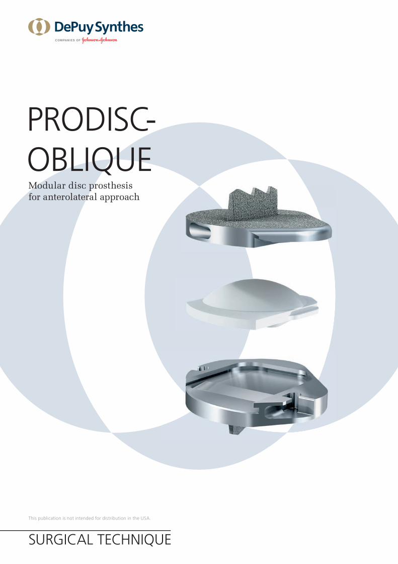
Modular disc prosthesis for anterolateral approach
PRODISC-OBLIQUE
This publication is not intended for distribution in the USA.
SURGICAL TECHNIQUE

Image intensifier control
WarningThis description alone does not provide sufficient background for direct use of DePuy Synthes products. Instruction by a surgeon experienced in handling these products is mandatory.
Processing, Reprocessing, Care and MaintenanceFor general guidelines, function control and dismantling of multi-part instruments, please contact your local sales representative or refer to:http://emea.depuysynthes.com/hcp/reprocessing-care-maintenanceFor general information about reprocessing, care and maintenance of Synthes reusable devices, instrument trays and cases, please consult the Important Information leaflet (SE_023827) or refer to: http://emea.depuysynthes.com/hcp/reprocessing-care-maintenance
Prodisc-Oblique Surgical Technique DePuy Synthes 1
INTRODUCTION Prodisc-Oblique 2
Indications and Contraindications 4
Kinematics 6
SURGICAL TECHNIQUE Five Rules for Successful Insertion 8
Preoperative Planning 9
Patient Positioning 11
Approach 12
Endplate Preparation and Segment Mobilization 13
Implant Insertion 16
PRODUCT INFORMATION Implants 31
Instruments 32
Vario Cases and Sets 37
Other Synthes Products for Access, Discectomy and Endplate Preparation 39
BIBLIOGRAPHY 42
TABLE OF CONTENTS
Note: Attending training is mandatory. Please contact your local Synthes representative for further information.
2 DePuy Synthes Prodisc-Oblique Surgical Technique
PRODISC-OBLIQUE
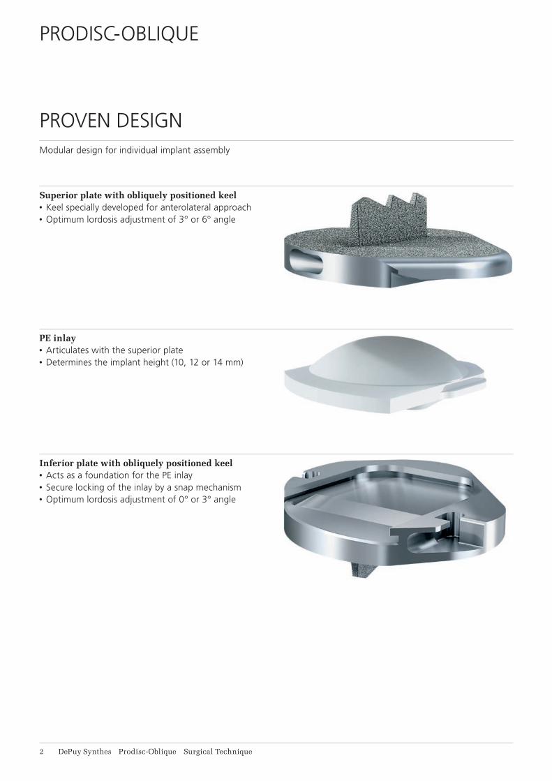
PROVEN DESIGNModular design for individual implant assembly
Superior plate with obliquely positioned keel• Keel specially developed for anterolateral approach• Optimum lordosis adjustment of 3° or 6° angle
PE inlay• Articulates with the superior plate• Determines the implant height (10, 12 or 14 mm)
Inferior plate with obliquely positioned keel • Acts as a foundation for the PE inlay• Secure locking of the inlay by a snap mechanism• Optimum lordosis adjustment of 0° or 3° angle
Prodisc-Oblique Surgical Technique DePuy Synthes 3
MINIMALLY INVASIVEANTEROLATERAL APPROACH Minimal invasive access• Less mobilization of major vessels and the hypogastric
plexus• Potentially reduced risk of arterial thromboembolism
Surgical technique• High precision in positioning prosthesis with specially
developed instruments• Modular prosthesis structure for a frictionless
positioning
Good primary and secondary stability• Central keel for implant anchorage in the bone• Rough Titanium surface coating potentially allows for
osteointegration and high resistance to friction
Ball and socket principle• Preserves mobility of the functional spinal unit• Preserves the physiological range of motion• Reduces the segmental shearing forces
Reliable, tested materials• Cobalt-chromium-molybdenum (CoCrMo)
implant plates• C.P. Titanium plasma spray coating allows for osteo-
integration and provides high frictional resistance• Insert consists of ultra-high-molecular weight
polyethylene (UHMWPE) and has a tantalum marker for visualization.

4 DePuy Synthes Prodisc-Oblique Surgical Technique
INDICATIONS AND CONTRAINDICATIONS
Intended useProdisc-Oblique implants are used to replace lumbar inter vertebral discs and to restore disc height and segmental motion at vertebral levels L1 to L5. They are inserted by using the antero-lateral approach.
IndicationsLumbar discopathy for levels L1 to L5, for which patient’s anatomy allows the antero-lateral approach.¹
Contraindications• Vertebral level L5/S1• Any circumstances preventing antero-lateral access
to the spinal column (including extensive abdominal and/or retroperitoneal surgery from the left)
• Compromised vertebral bodies at affected level due to current or past trauma (fractures)
• Substantial loss of disc height, where applied segmental distraction may lead to damage of the great vessels
• Isolated radicular compression syndromes, especially due to disc herniation
• Bony lumbar spinal stenosis• Spondylolysthesis/Retrolisthesis• Pars defect• Complete laminectomy• Osteoporosis and osteopenia²• Active systemic infection or infection localized to the
site of implantation• Allergy or sensitivity to implant materials (foreign body
sensitivity to the implant materials)• Adipositas• Pregnancy• Involved vertebral endplate dimensionally smaller than
the minimum implant footprint size in both the medial-lateral and the anterior-posterior directions
• Severe abnormality of the endplate (e.g. large Schmorl nodes)
• Facet joint disease or degeneration
¹ The accessibility of the disc segment L1/L2 depends on the patient’s individual anatomy
² Bone density T index <-1 SD, according to DXA/DEXA, dual-X-ray apsorptiometry
Prodisc-Oblique Surgical Technique DePuy Synthes 5
• Systemic and/or metabolic diseases• Back or leg pain of unknown etiology• Active malignancy (e.g. tumors)• Acute or chronic infections (systemic and/or local)• Dependency on pharmaceutical drugs or drug abuse,
or alcoholism• Predominant psychosocial factors/illnesses• Foraminal or lateral spinal canal stenosis• Lack of patient compliance• Any cases not listed in the indications
Patient exclusion recommendationsPatient selection is one of the most important factors contributing to the outcome of the total disc replace-ment procedure. The following may affect clinical out-comes:• A condition of senility or mental illness, alcoholism or
smoking• Dependency on pharmaceutical drugs or drug abuse• The patient’s occupation or activity level• Compromised vertebral bodies at affected level due to
current or past trauma (fractures) • Substantial loss of disc height, where applied segmen-
tal distraction may lead to damage of the great vessels • Involved vertebral endplate dimensionally smaller than
the minimum implant footprint size in both the medial-lateral and the anterior-posterior directions
• Severe abnormality of the endplate (e.g. large Schmorl nodes)
10° 13°15° 20°
5° 7°
6 DePuy Synthes Prodisc-Oblique Surgical Technique
KINEMATICS
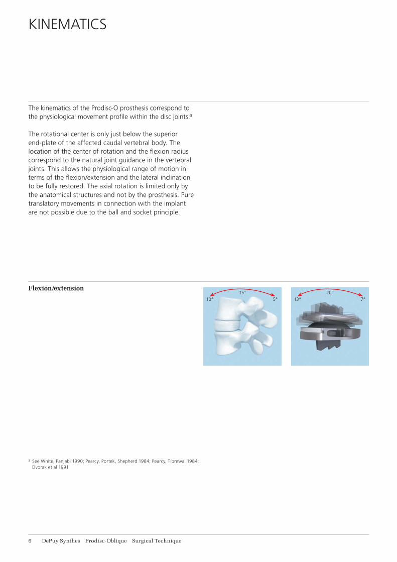
The kinematics of the Prodisc-O prosthesis correspond to the physiological movement profile within the disc joints:³
The rotational center is only just below the superior end-plate of the affected caudal vertebral body. The location of the center of rotation and the flexion radius correspond to the natural joint guidance in the vertebral joints. This allows the physiological range of motion in terms of the flexion/extension and the lateral inclination to be fully restored. The axial rotation is limited only by the anatomical structures and not by the prosthesis. Pure translatory movements in connection with the implant are not possible due to the ball and socket principle.
Flexion/extension
³ See White, Panjabi 1990; Pearcy, Portek, Shepherd 1984; Pearcy, Tibrewal 1984; Dvorak et al 1991
5° 10°10° 20°
5° 10°
3°6°
3°360°
Prodisc-Oblique Surgical Technique DePuy Synthes 7
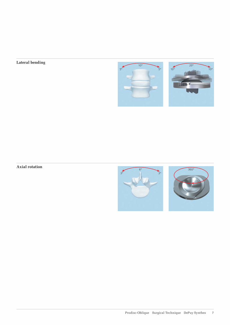
Lateral bending
Axial rotation
8 DePuy Synthes Prodisc-Oblique Surgical Technique
FIVE RULES FOR SUCCESSFUL INSERTION
1a. Do not use if the segmental distraction is insufficient or can damage the anatomical structures due to substantial loss of disc height.
1b. Careful symmetrical mobilization of the affected segment is essential.
2. Never use Prodisc-O implants where bone density is T < –1.4
3. The inferior and superior plate of the implant have to be positioned in parallel and have to line up directly. The distance of the implant to the posterior edge of the disc should be 1–1.5 mm.
4. The central positioning of the implant plates from an anterior to posterior view is crucial to ensure proper function of the prosthesis.
5. After inserting the PE inlay always ensure that it is locked in position.
4 Bone density T index <-1 SD, according to DXA/DEXA, dual-X-ray apsorptiometry
Prodisc-Oblique Surgical Technique DePuy Synthes 9
PREOPERATIVE PLANNING
A detailed and correct assessment of the indication is the key for successful results in arthroplasty.
If conservative treatment methods have failed to yield positive results, a diagnosis can be made on the basis of the indication profi le as to whether the use of an artifi cial disc could be a promising option for the patient in question.
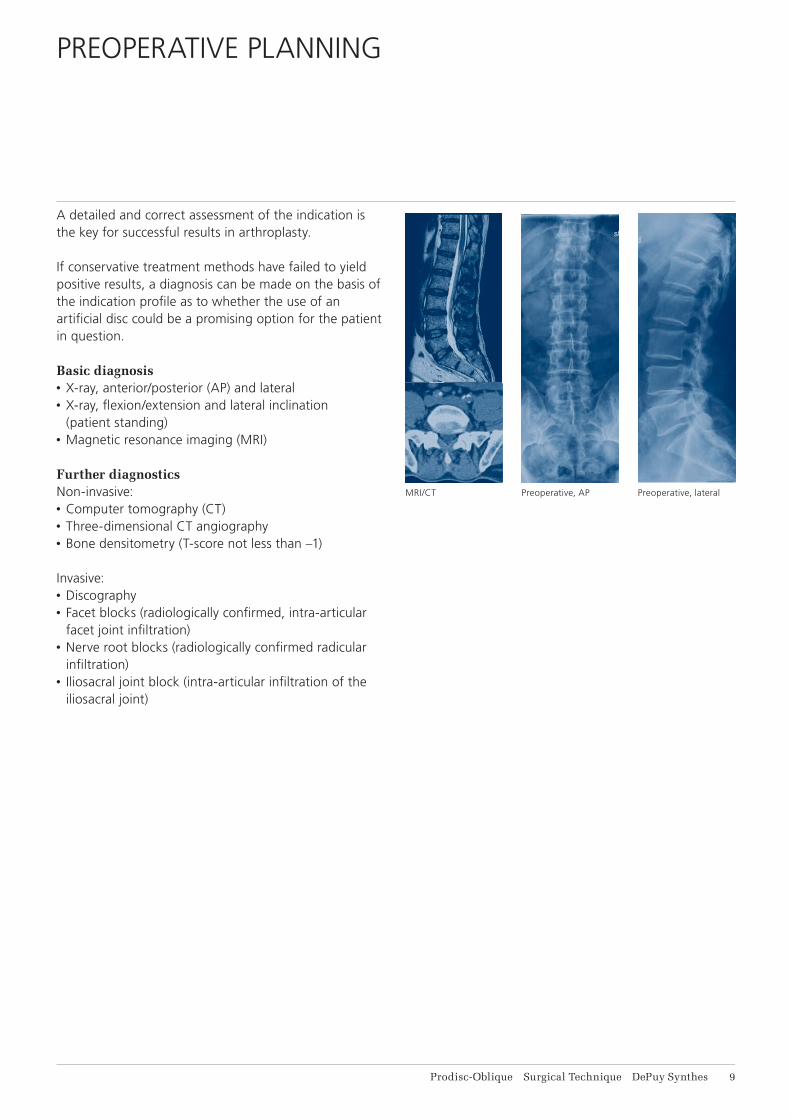
Basic diagnosis• X-ray, anterior/posterior (AP) and lateral• X-ray, fl exion/extension and lateral inclination
(patient standing)• Magnetic resonance imaging (MRI)
Further diagnosticsNon-invasive:• Computer tomography (CT)• Three-dimensional CT angiography• Bone densitometry (T-score not less than –1)
Invasive:• Discography• Facet blocks (radiologically confi rmed, intra-articular
facet joint infi ltration)• Nerve root blocks (radiologically confi rmed radicular
infi ltration)• Iliosacral joint block (intra-articular infi ltration of the
iliosacral joint)
MRI/CT Preoperative, AP Preoperative, lateral
11 DePuy Synthes Prodisc-Oblique Surgical Technique
Preoperative Planning
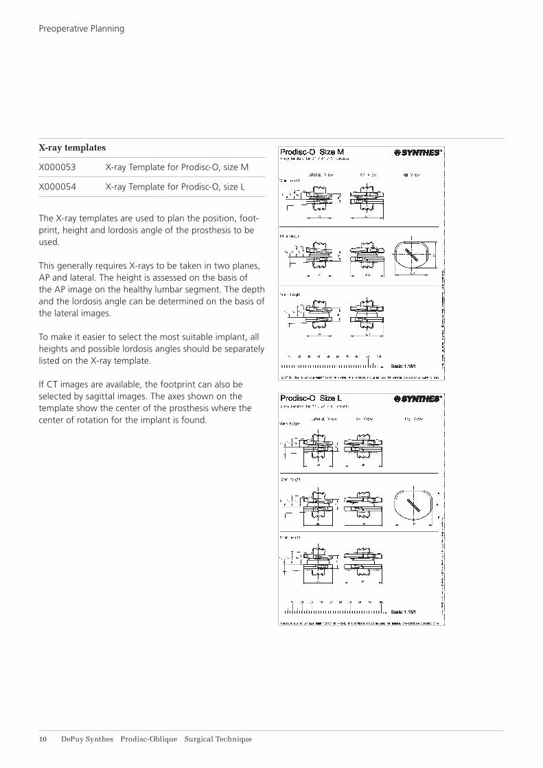
X-ray templates
X000053 X-ray Template for Prodisc-O, size M
X000054 X-ray Template for Prodisc-O, size L
The X-ray templates are used to plan the position, foot-print, height and lordosis angle of the prosthesis to be used.
This generally requires X-rays to be taken in two planes, AP and lateral. The height is assessed on the basis of the AP image on the healthy lumbar segment. The depth and the lordosis angle can be determined on the basis of the lateral images.
To make it easier to select the most suitable implant, all heights and possible lordosis angles should be separately listed on the X-ray template.
If CT images are available, the footprint can also be selected by sagittal images. The axes shown on the template show the center of the prosthesis where the center of rotation for the implant is found.
1 2
3
Prodisc-Oblique Surgical Technique DePuy Synthes 11
PATIENT POSITIONING
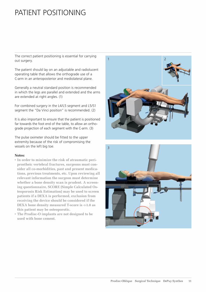
The correct patient positioning is essential for carrying out surgery.
The patient should lay on an adjustable and radiolucent operating table that allows the orthograde use of a C-arm in an anteroposterior and mediolateral plane.
Generally a neutral standard position is recommended in which the legs are parallel and extended and the arms are extended at right angles. (1)
For combined surgery in the L4/L5 segment and L5/S1 segment the “Da Vinci position” is recommended. (2)
It is also important to ensure that the patient is positioned far towards the foot end of the table, to allow an ortho-grade projection of each segment with the C-arm. (3)
The pulse oximeter should be fi tted to the upper extremity because of the risk of compromising the vessels on the left big toe.
Notes:• In order to minimize the risk of atraumatic peri-
prostheic vertebral fractures, surgeons must con-sider all co-morbidities, past and present medica-tions, previous treatments, etc. Upon reviewing all relevant information the surgeon must determine whether a bone density scan is prudent. A screen-ing questionnaire, SCORE (Simple Calculated Os-teoporosis Risk Estimation) may be used to screen patients if a DEXA is performed, exclusion from receiving the device should be considered if the DEXA bone density measured T-score is <-1.0 as this patient may be osteoporotic.
• The Prodisc-O implants are not designed to be used with bone cement.
12 DePuy Synthes Prodisc-Oblique Surgical Technique
APPROACH
Recommended systems
187.310 SynFrame Basic System in Vario Case
01.609.102 Set SynFrame RL, lumbar
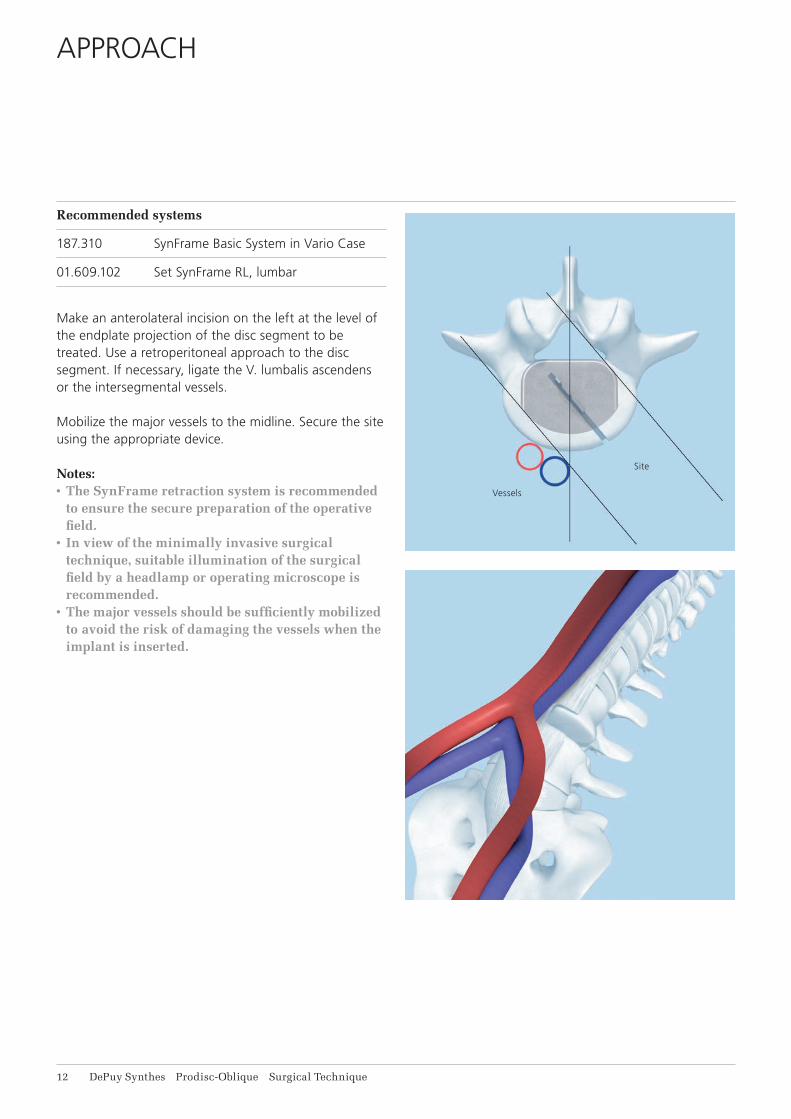
Make an anterolateral incision on the left at the level of the endplate projection of the disc segment to be treated. Use a retroperitoneal approach to the disc segment. If necessary, ligate the V. lumbalis ascendens or the intersegmental vessels.
Mobilize the major vessels to the midline. Secure the site using the appropriate device.
Notes:• The SynFrame retraction system is recommended
to ensure the secure preparation of the operative field.
• In view of the minimally invasive surgical technique, suitable illumination of the surgical field by a headlamp or operating microscope is recommended.
• The major vessels should be sufficiently mobilized to avoid the risk of damaging the vessels when the implant is inserted.
Vessels
Site
Prodisc-Oblique Surgical Technique DePuy Synthes 13
ENDPLATE PREPARATION AND SEGMENT MOBILIZATION
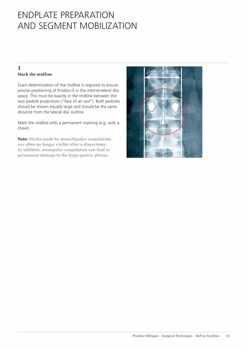
1Mark the midline
Exact determination of the midline is required to ensure precise positioning of Prodisc-O in the intervertebral disc space. This must be exactly in the midline between the two pedicle projections (“face of an owl”). Both pedicles should be shown equally large and should be the same distance from the lateral disc outline.
Mark the midline with a permanent marking (e.g. with a chisel).
Note: Marks made by mono/bipolar coagulation are often no longer visible after a discectomy. In addition, monopolar coagulation can lead to permanent damage to the hypo- gastric plexus.
1
2
14 DePuy Synthes Prodisc-Oblique Surgical Technique
Endplate Preparation and Segment Mobilization
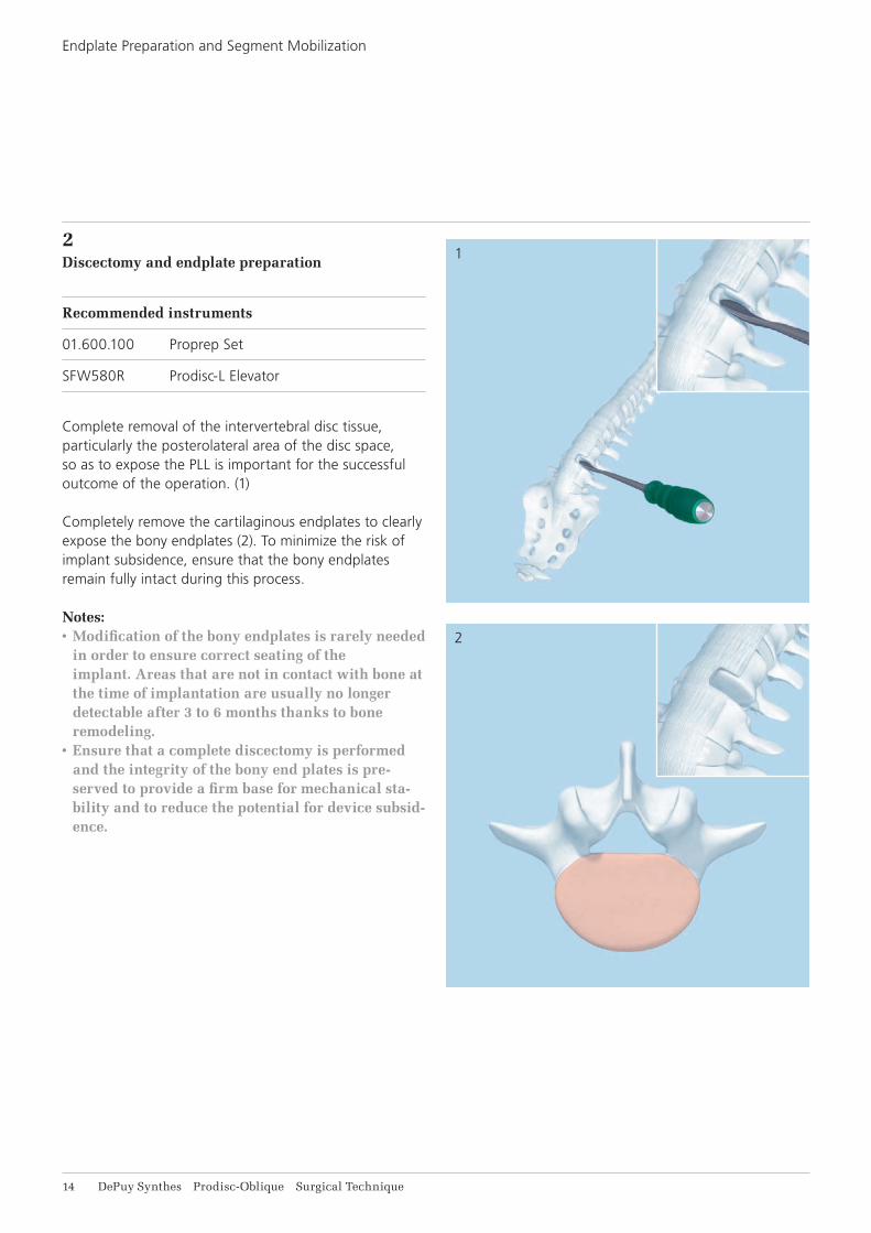
2Discectomy and endplate preparation
Recommended instruments
01.600.100 Proprep Set
SFW580R Prodisc-L Elevator
Complete removal of the intervertebral disc tissue, particularly the posterolateral area of the disc space, so as to expose the PLL is important for the successful outcome of the operation. (1)
Completely remove the cartilaginous endplates to clearly expose the bony endplates (2). To minimize the risk of implant subsidence, ensure that the bony endplates remain fully intact during this process.
Notes:• Modification of the bony endplates is rarely needed
in order to ensure correct seating of the implant. Areas that are not in contact with bone at the time of implantation are usually no longer detectable after 3 to 6 months thanks to bone remodeling.
• Ensure that a complete discectomy is performed and the integrity of the bony end plates is pre-served to provide a firm base for mechanical sta-bility and to reduce the potential for device subsid-ence.
1
2
Prodisc-Oblique Surgical Technique DePuy Synthes 15
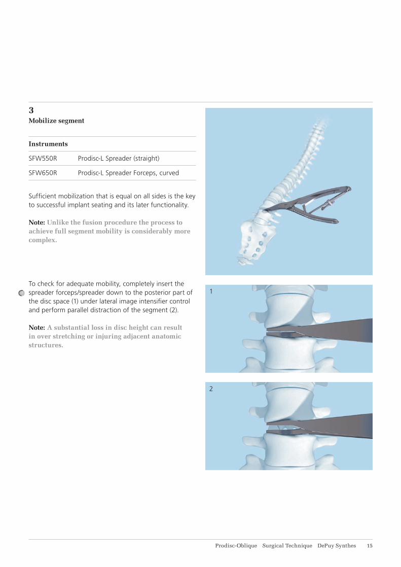
3Mobilize segment
Instruments
SFW550R Prodisc-L Spreader (straight)
SFW650R Prodisc-L Spreader Forceps, curved
Suffi cient mobilization that is equal on all sides is the key to successful implant seating and its later functionality.
Note: Unlike the fusion procedure the process to achieve full segment mobility is considerably more complex.
To check for adequate mobility, completely insert the spreader forceps/spreader down to the posterior part of the disc space (1) under lateral image intensifi er control and perform parallel distraction of the segment (2).
Note: A substantial loss in disc height can result in over stretching or injuring adjacent anatomic structures.
16 DePuy Synthes Prodisc-Oblique Surgical Technique
IMPLANT INSERTION
1Select and assemble trial implant
Instruments
03.821.101 Handle for Trial Implants
03.821.021–029 Trial Implants, size M
03.821.041–049 Trial Implants, size L
03.821.139 Centering Device
314.270 Hex Screwdriver, large, B 3.5 mm, with groove, length 240 mm
Optional
03.821.011–019 Trial Implants, size M, narrow
03.821.021–039 Trial Implants, size L, narrow
The following are determined with the trial implant:• Lordosis angle• Height• Footprint size• Keel chisels• Implant position
The correct choice and positioning is essential for the success of the procedure.
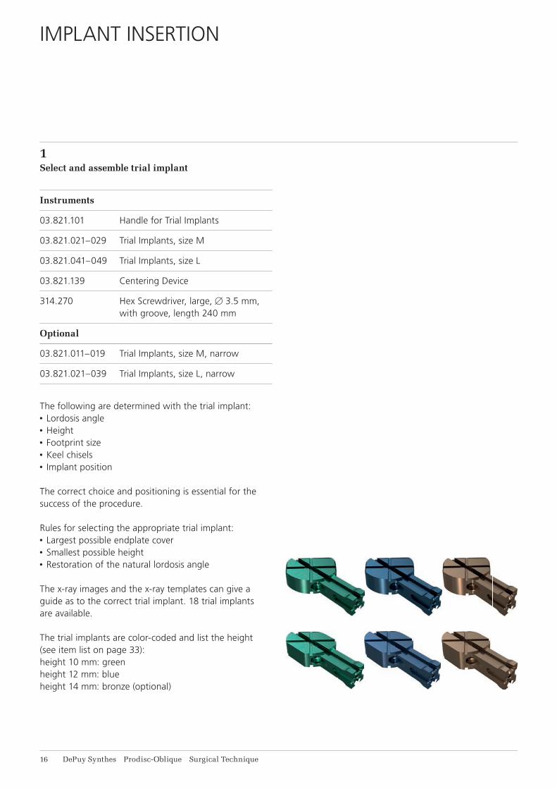
Rules for selecting the appropriate trial implant:• Largest possible endplate cover • Smallest possible height• Restoration of the natural lordosis angle
The x-ray images and the x-ray templates can give a guide as to the correct trial implant. 18 trial implants are available.
The trial implants are color-coded and list the height (see item list on page 33):height 10 mm: greenheight 12 mm: blueheight 14 mm: bronze (optional)
u
v
w
Prodisc-Oblique Surgical Technique DePuy Synthes 17
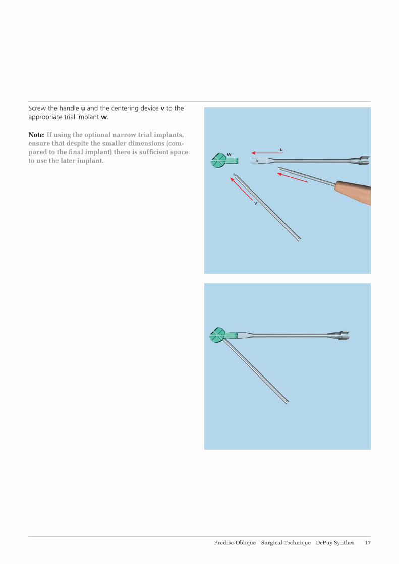
Screw the handle u and the centering device v to the appropriate trial implant w.
Note: If using the optional narrow trial implants, ensure that despite the smaller dimensions (com-pared to the fi nal implant) there is suffi cient space to use the later implant.
1
18 DePuy Synthes Prodisc-Oblique Surgical Technique
Implant Insertion
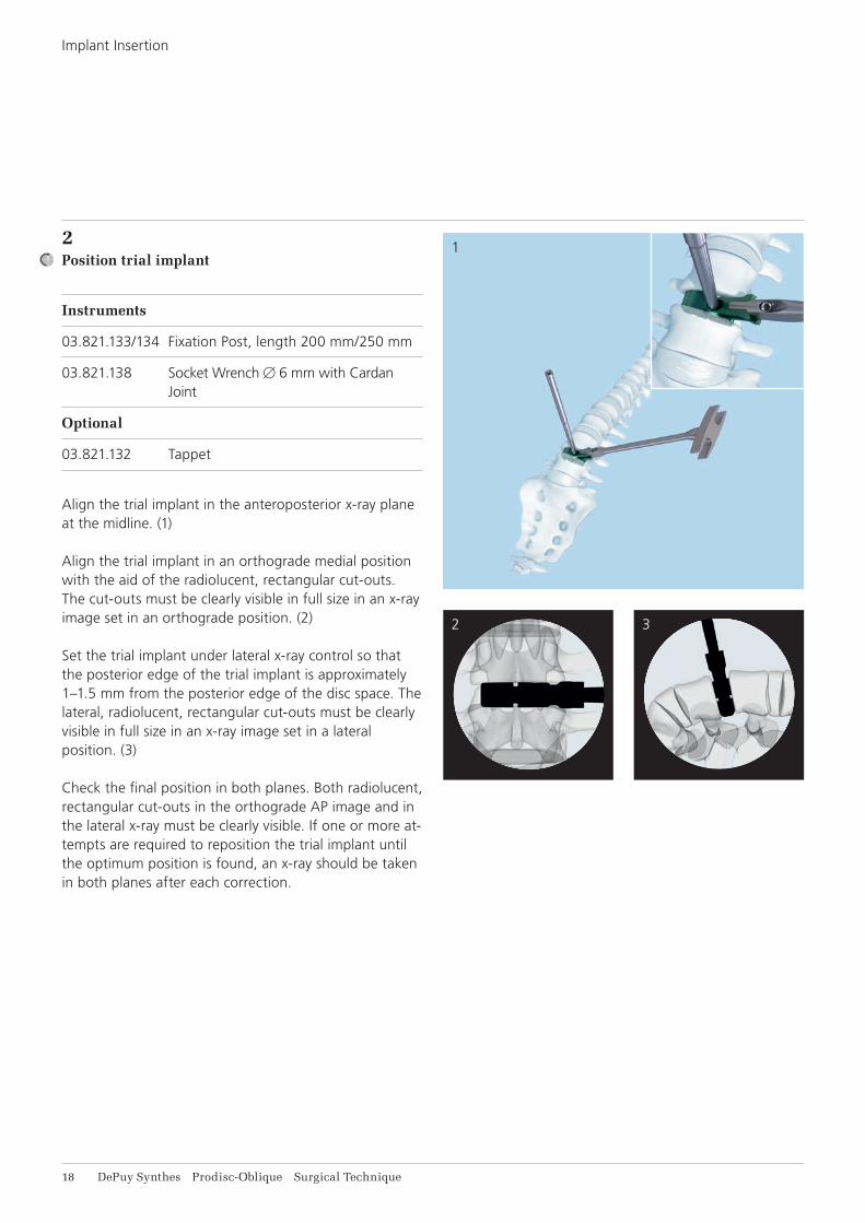
2Position trial implant
Instruments
03.821.133/134 Fixation Post, length 200 mm/250 mm
03.821.138 Socket Wrench B 6 mm with Cardan Joint
Optional
03.821.132 Tappet
Align the trial implant in the anteroposterior x-ray plane at the midline. (1)
Align the trial implant in an orthograde medial position with the aid of the radiolucent, rectangular cut-outs. The cut-outs must be clearly visible in full size in an x-ray image set in an orthograde position. (2)
Set the trial implant under lateral x-ray control so that the posterior edge of the trial implant is approximately 1–1.5 mm from the posterior edge of the disc space. The lateral, radiolucent, rectangular cut-outs must be clearly visible in full size in an x-ray image set in a lateral position. (3)
Check the final position in both planes. Both radiolucent, rectangular cut-outs in the orthograde AP image and in the lateral x-ray must be clearly visible. If one or more at-tempts are required to reposition the trial implant until the optimum position is found, an x-ray should be taken in both planes after each correction.
2 3
4
Prodisc-Oblique Surgical Technique DePuy Synthes 19
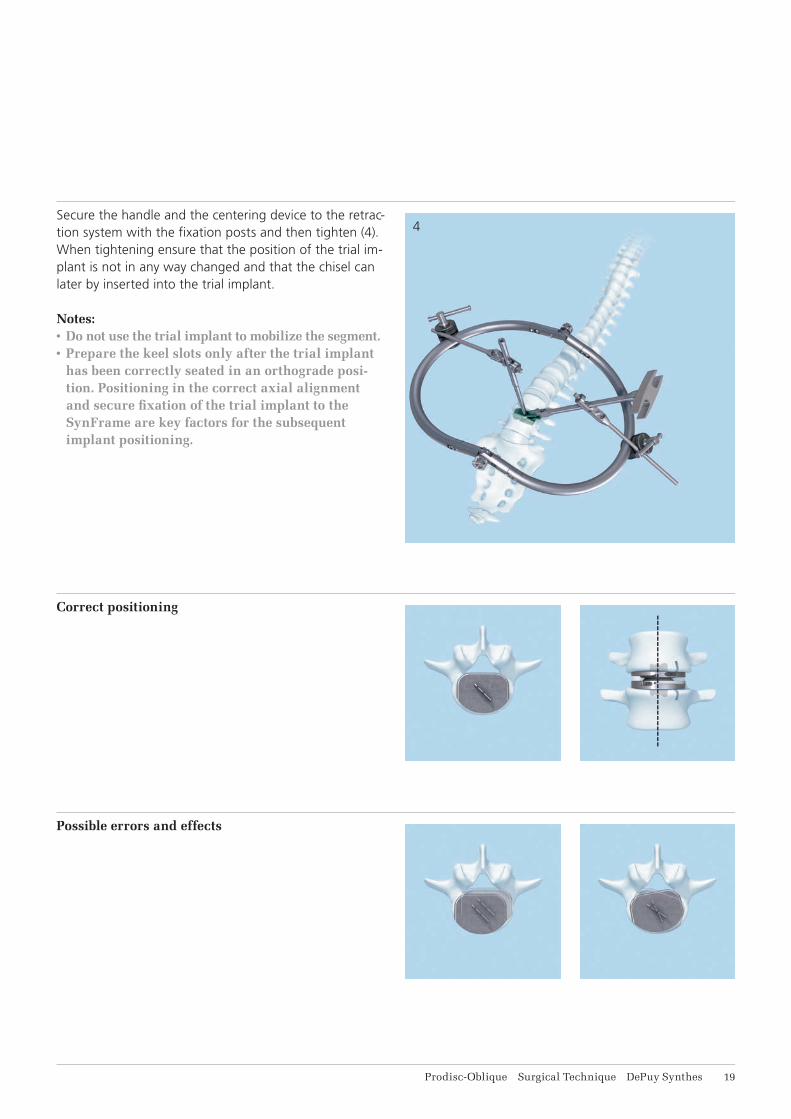
Secure the handle and the centering device to the retrac-tion system with the fi xation posts and then tighten (4). When tightening ensure that the position of the trial im-plant is not in any way changed and that the chisel can later by inserted into the trial implant.
Notes:• Do not use the trial implant to mobilize the segment.• Prepare the keel slots only after the trial implant
has been correctly seated in an orthograde posi-tion. Positioning in the correct axial alignment and secure fi xation of the trial implant to the SynFrame are key factors for the subsequent implant positioning.
Correct positioning
Possible errors and effects
3
21 DePuy Synthes Prodisc-Oblique Surgical Technique
Implant Insertion
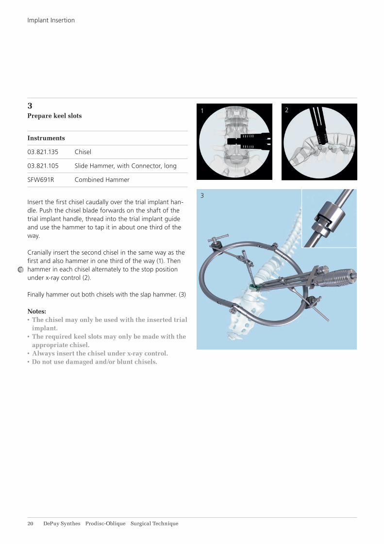
3Prepare keel slots
Instruments
03.821.135 Chisel
03.821.105 Slide Hammer, with Connector, long
SFW691R Combined Hammer
Insert the first chisel caudally over the trial implant han-dle. Push the chisel blade forwards on the shaft of the trial implant handle, thread into the trial implant guide and use the hammer to tap it in about one third of the way.
Cranially insert the second chisel in the same way as the first and also hammer in one third of the way (1). Then hammer in each chisel alternately to the stop position under x-ray control (2).
Finally hammer out both chisels with the slap hammer. (3)
Notes:• The chisel may only be used with the inserted trial
implant.• The required keel slots may only be made with the
appropriate chisel.• Always insert the chisel under x-ray control.• Do not use damaged and/or blunt chisels.
21

1
2
3
Prodisc-Oblique Surgical Technique DePuy Synthes 21
4Insert strut
Instruments
03.821.121–129 Struts, angled
03.821.138 Socket Wrench B 6 mm with Cardan Joint
SFW520 Prodisc-L Handle for Strut
Optional
03.821.111–119 Struts, straight
Struts are used in order to prevent the segment from collapsing when the trial implant is removed.
Unscrew the centering device and fi t an angled strut to the medial side of the trial implant. (1)
A straight strut can be placed laterally as a further op-tional aid. Adjust the straight strut according to the height of the disc and the depth of the surgical fi eld. (2)
Secure the strut to the SynFrame using the handle for strut and remove the trial implant. (3)
Precaution: Always position the strut fi rst and then remove the trial implant to avoid collapsing of the motion segment.
Precaution: Heterotopic ossifi cation (HO) is a possi-ble cause for fusion of the treated segment. Copious saline lavage is recommended to remove osteogenic stimuli (blood/bone marrow). HO might be reduced when bone wax is used to close cavities in the bone (screw holes) and open bone surfaces after removal of anterior osteophytes¹.
¹ See Barbagallo 2014
1
2
4
3
22 DePuy Synthes Prodisc-Oblique Surgical Technique
Implant Insertion
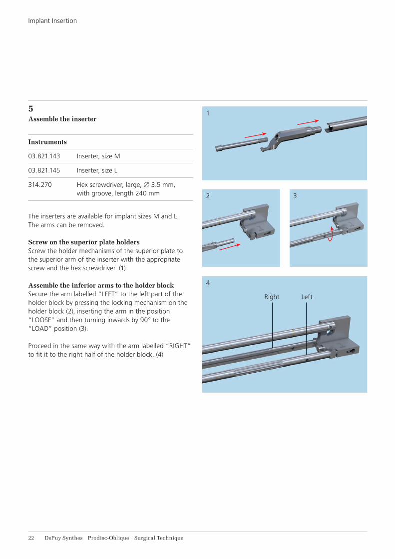
5Assemble the inserter
Instruments
03.821.143 Inserter, size M
03.821.145 Inserter, size L
314.270 Hex screwdriver, large, B 3.5 mm, with groove, length 240 mm
The inserters are available for implant sizes M and L. The arms can be removed.
Screw on the superior plate holdersScrew the holder mechanisms of the superior plate to the superior arm of the inserter with the appropriate screw and the hex screwdriver. (1)
Assemble the inferior arms to the holder blockSecure the arm labelled “LEFT” to the left part of the holder block by pressing the locking mechanism on the holder block (2), inserting the arm in the position “LOOSE” and then turning inwards by 90° to the “LOAD” position (3).
Proceed in the same way with the arm labelled “RIGHT” to fit it to the right half of the holder block. (4)
Right Left
Prodisc-Oblique Surgical Technique DePuy Synthes 23
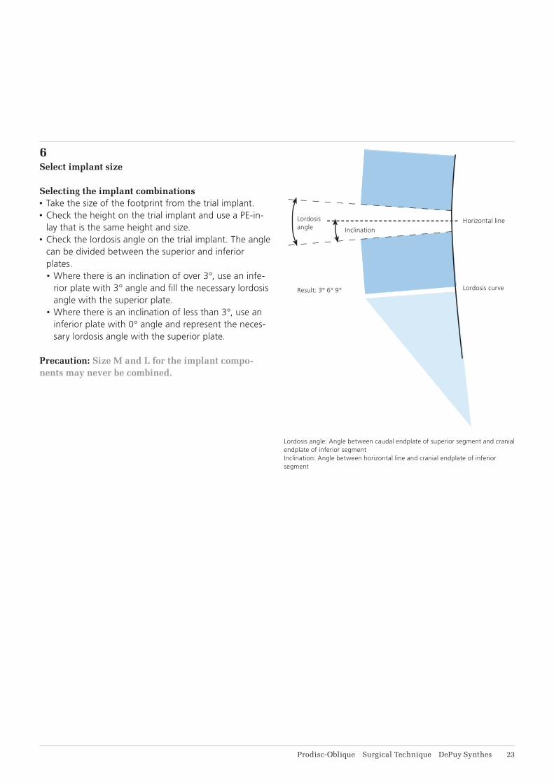
6Select implant size
Selecting the implant combinations• Take the size of the footprint from the trial implant. • Check the height on the trial implant and use a PE-in-
lay that is the same height and size.• Check the lordosis angle on the trial implant. The angle
can be divided between the superior and inferior plates.• Where there is an inclination of over 3°, use an infe-
rior plate with 3° angle and fi ll the necessary lordosis angle with the superior plate.
• Where there is an inclination of less than 3°, use an inferior plate with 0° angle and represent the neces-sary lordosis angle with the superior plate.
Precaution: Size M and L for the implant compo-nents may never be combined.
Lordosis angle: Angle between caudal endplate of superior segment and cranial endplate of inferior segmentInclination: Angle between horizontal line and cranial endplate of inferior segment
Horizontal line
Lordosis curve
Inclination
Result: 3° 6° 9°
Lordosisangle
1
3
2
4
24 DePuy Synthes Prodisc-Oblique Surgical Technique
Implant Insertion
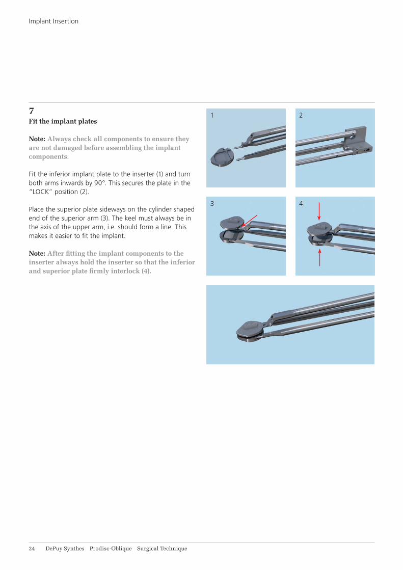
7Fit the implant plates
Note: Always check all components to ensure they are not damaged before assembling the implant components.
Fit the inferior implant plate to the inserter (1) and turn both arms inwards by 90°. This secures the plate in the “LOCK” position (2).
Place the superior plate sideways on the cylinder shaped end of the superior arm (3). The keel must always be in the axis of the upper arm, i.e. should form a line. This makes it easier to fit the implant.
Note: After fitting the implant components to the inserter always hold the inserter so that the inferior and superior plate firmly interlock (4).
1
2
Prodisc-Oblique Surgical Technique DePuy Synthes 25
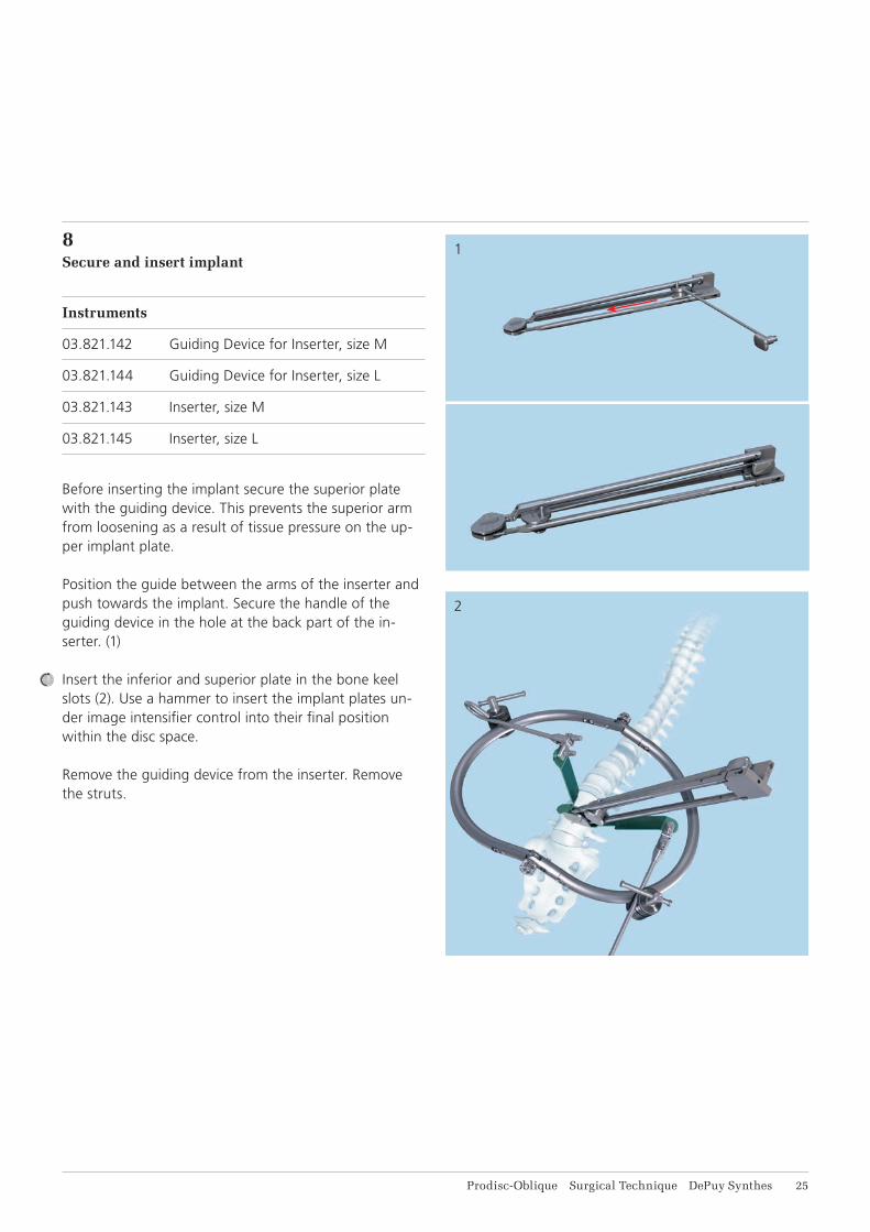
8Secure and insert implant
Instruments
03.821.142 Guiding Device for Inserter, size M
03.821.144 Guiding Device for Inserter, size L
03.821.143 Inserter, size M
03.821.145 Inserter, size L
Before inserting the implant secure the superior plate with the guiding device. This prevents the superior arm from loosening as a result of tissue pressure on the up-per implant plate.
Position the guide between the arms of the inserter and push towards the implant. Secure the handle of the guiding device in the hole at the back part of the in-serter. (1)
Insert the inferior and superior plate in the bone keel slots (2). Use a hammer to insert the implant plates un-der image intensifi er control into their fi nal position within the disc space.
Remove the guiding device from the inserter. Remove the struts.
1
2
26 DePuy Synthes Prodisc-Oblique Surgical Technique
Implant Insertion
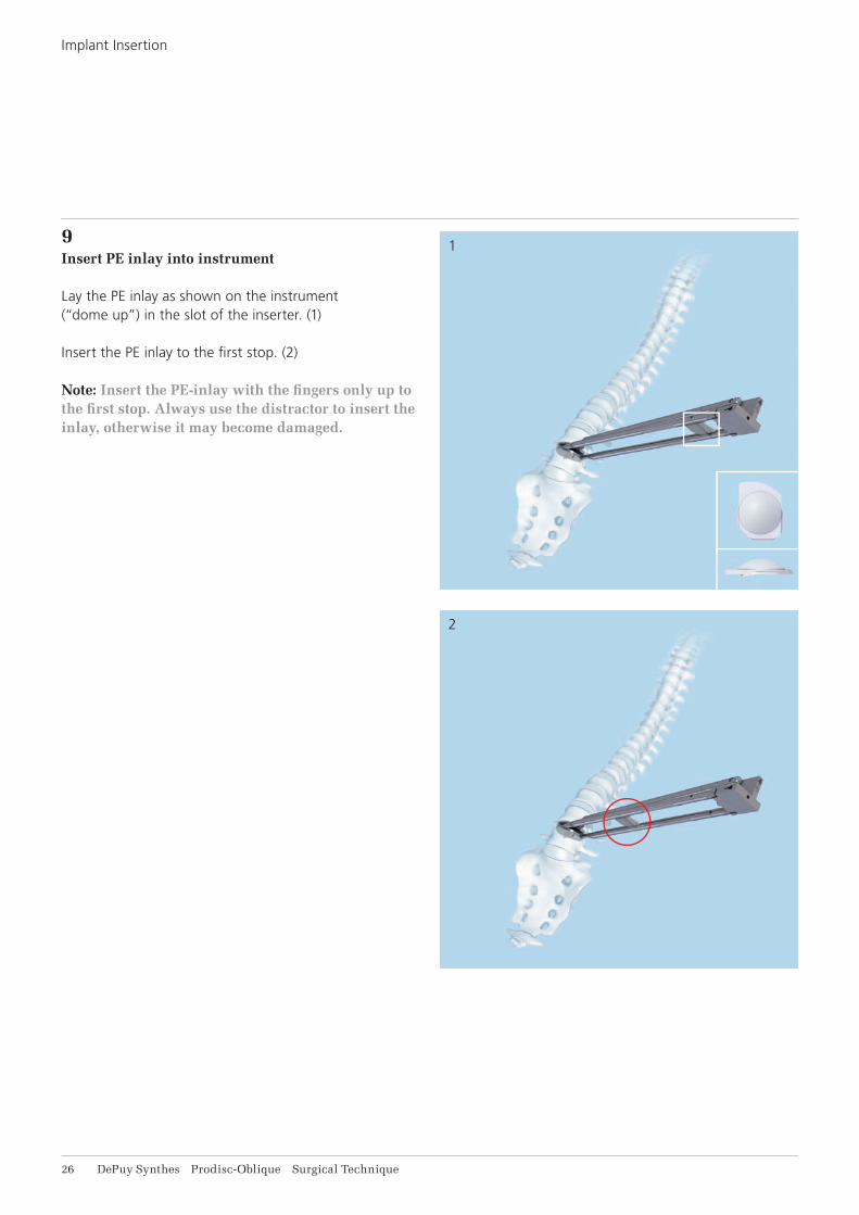
9Insert PE inlay into instrument
Lay the PE inlay as shown on the instrument (“dome up”) in the slot of the inserter. (1)
Insert the PE inlay to the fi rst stop. (2)
Note: Insert the PE-inlay with the fi ngers only up to the fi rst stop. Always use the distractor to insert the inlay, otherwise it may become damaged.
1
2
3
Prodisc-Oblique Surgical Technique DePuy Synthes 27
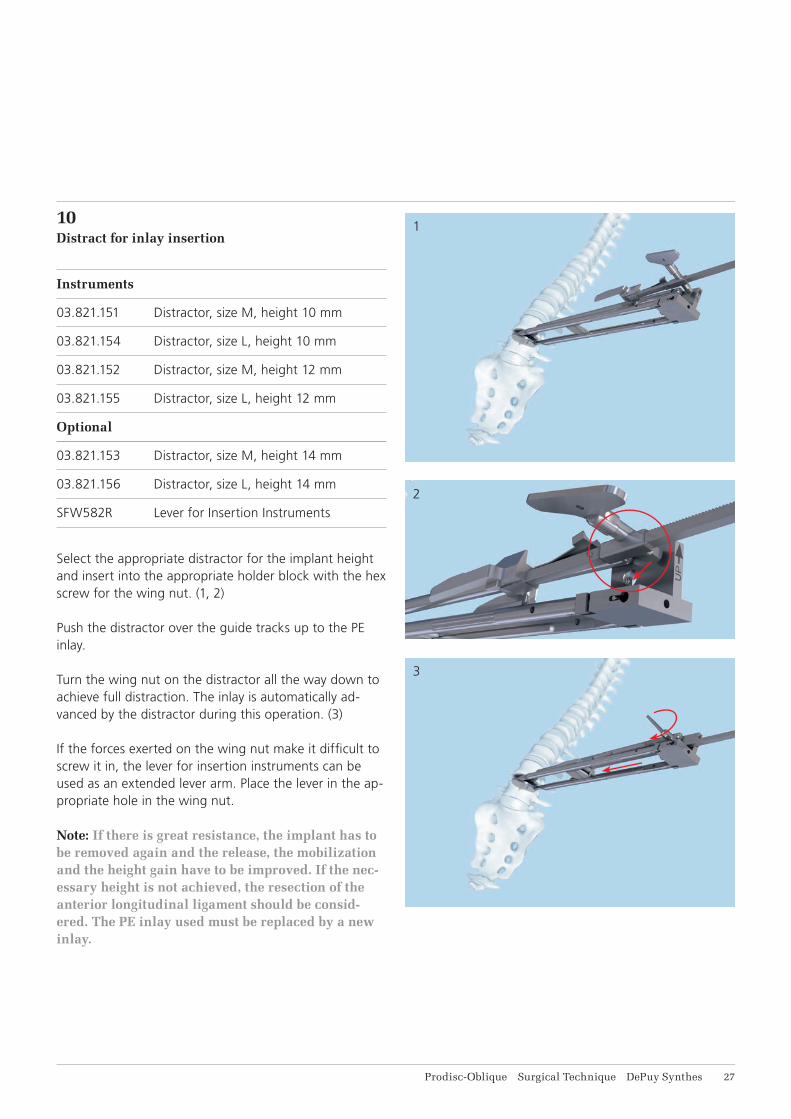
10Distract for inlay insertion
Instruments
03.821.151 Distractor, size M, height 10 mm
03.821.154 Distractor, size L, height 10 mm
03.821.152 Distractor, size M, height 12 mm
03.821.155 Distractor, size L, height 12 mm
Optional
03.821.153 Distractor, size M, height 14 mm
03.821.156 Distractor, size L, height 14 mm
SFW582R Lever for Insertion Instruments
Select the appropriate distractor for the implant height and insert into the appropriate holder block with the hex screw for the wing nut. (1, 2)
Push the distractor over the guide tracks up to the PE inlay.
Turn the wing nut on the distractor all the way down to achieve full distraction. The inlay is automatically ad-vanced by the distractor during this operation. (3)
If the forces exerted on the wing nut make it diffi cult to screw it in, the lever for insertion instruments can be used as an extended lever arm. Place the lever in the ap-propriate hole in the wing nut.
Note: If there is great resistance, the implant has to be removed again and the release, the mobilization and the height gain have to be improved. If the nec-essary height is not achieved, the resection of the anterior longitudinal ligament should be consid-ered. The PE inlay used must be replaced by a new inlay.
1
2
28 DePuy Synthes Prodisc-Oblique Surgical Technique
Implant Insertion
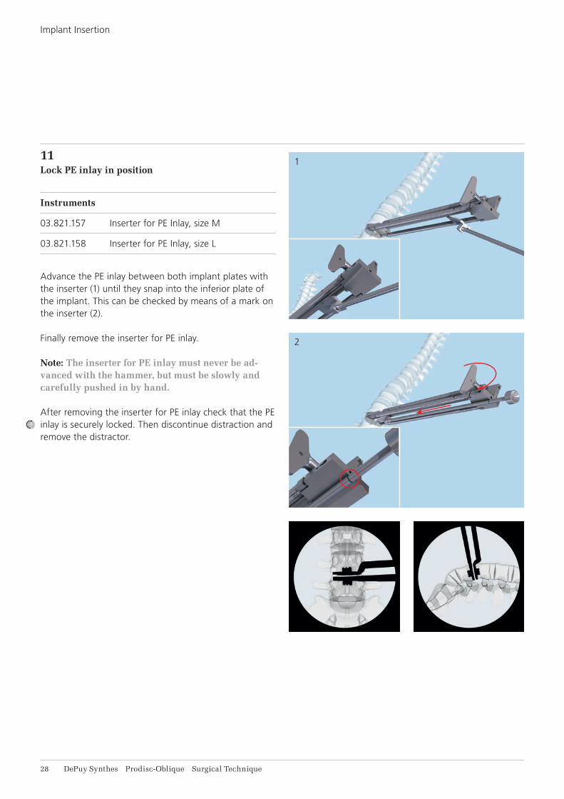
11Lock PE inlay in position
Instruments
03.821.157 Inserter for PE Inlay, size M
03.821.158 Inserter for PE Inlay, size L
Advance the PE inlay between both implant plates with the inserter (1) until they snap into the inferior plate of the implant. This can be checked by means of a mark on the inserter (2).
Finally remove the inserter for PE inlay.
Note: The inserter for PE inlay must never be ad-vanced with the hammer, but must be slowly and carefully pushed in by hand.
After removing the inserter for PE inlay check that the PE inlay is securely locked. Then discontinue distraction and remove the distractor.
Prodisc-Oblique Surgical Technique DePuy Synthes 29
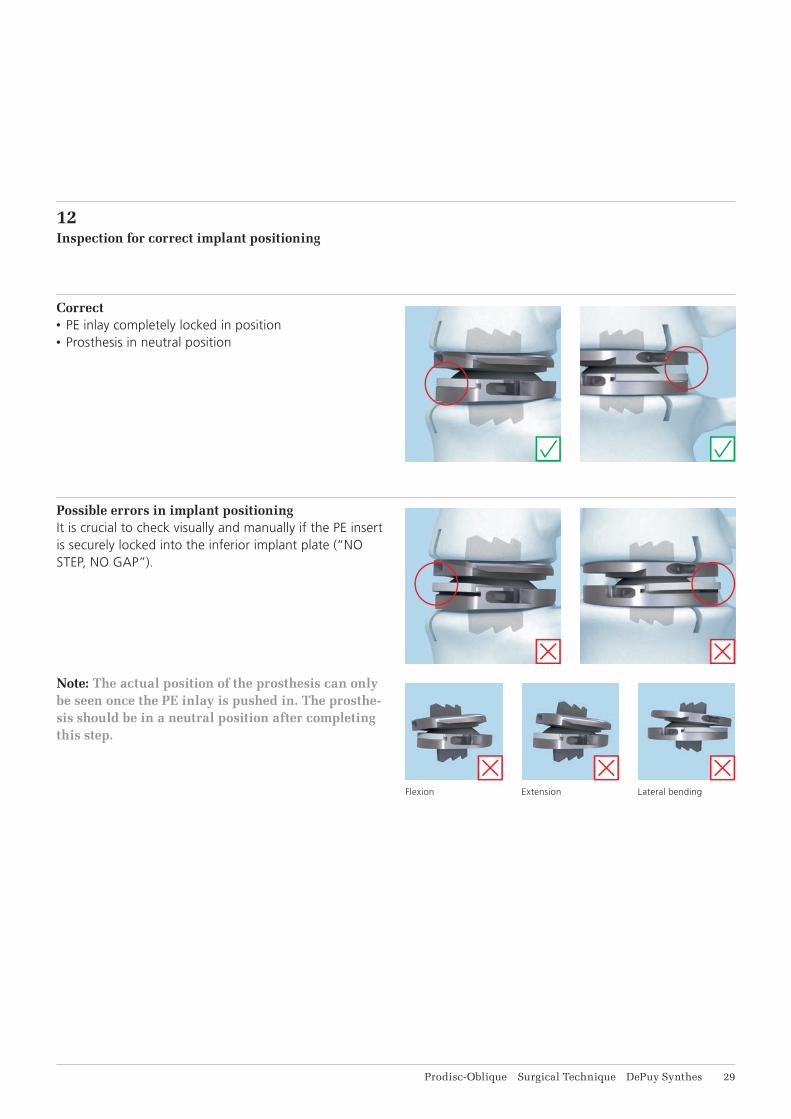
12Inspection for correct implant positioning
Possible errors in implant positioningIt is crucial to check visually and manually if the PE insert is securely locked into the inferior implant plate (“NO STEP, NO GAP”).
Note: The actual position of the prosthesis can only be seen once the PE inlay is pushed in. The prosthe-sis should be in a neutral position after completing this step.
Flexion Extension Lateral bending
Correct• PE inlay completely locked in position• Prosthesis in neutral position
1
2
31 DePuy Synthes Prodisc-Oblique Surgical Technique
Implant Insertion
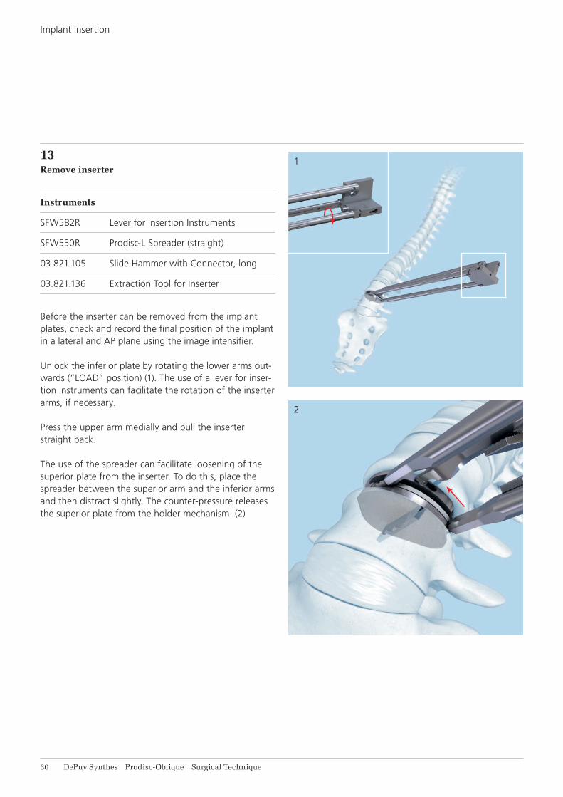
13Remove inserter
Instruments
SFW582R Lever for Insertion Instruments
SFW550R Prodisc-L Spreader (straight)
03.821.105 Slide Hammer with Connector, long
03.821.136 Extraction Tool for Inserter
Before the inserter can be removed from the implant plates, check and record the final position of the implant in a lateral and AP plane using the image intensifier.
Unlock the inferior plate by rotating the lower arms out-wards (“LOAD” position) (1). The use of a lever for inser-tion instruments can facilitate the rotation of the inserter arms, if necessary.
Press the upper arm medially and pull the inserter straight back.
The use of the spreader can facilitate loosening of the superior plate from the inserter. To do this, place the spreader between the superior arm and the inferior arms and then distract slightly. The counter-pressure releases the superior plate from the holder mechanism. (2)
Prodisc-Oblique Surgical Technique DePuy Synthes 31
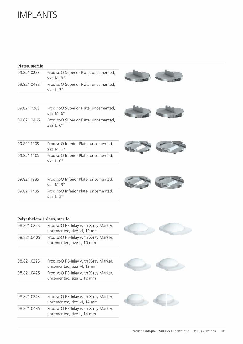
IMPLANTS
Plates, sterile
09.821.023S Prodisc-O Superior Plate, uncemented, size M, 3°
09.821.043S Prodisc-O Superior Plate, uncemented, size L, 3°
09.821.026S Prodisc-O Superior Plate, uncemented, size M, 6°
09.821.046S Prodisc-O Superior Plate, uncemented, size L, 6°
09.821.120S Prodisc-O Inferior Plate, uncemented, size M, 0°
09.821.140S Prodisc-O Inferior Plate, uncemented, size L, 0°
09.821.123S Prodisc-O Inferior Plate, uncemented, size M, 3°
09.821.143S Prodisc-O Inferior Plate, uncemented, size L, 3°
Polyethylene inlays, sterile
08.821.020S Prodisc-O PE-Inlay with X-ray Marker, uncemented, size M, 10 mm
08.821.040S Prodisc-O PE-Inlay with X-ray Marker, uncemented, size L, 10 mm
08.821.022S Prodisc-O PE-Inlay with X-ray Marker, uncemented, size M, 12 mm
08.821.042S Prodisc-O PE-Inlay with X-ray Marker, uncemented, size L, 12 mm
08.821.024S Prodisc-O PE-Inlay with X-ray Marker, uncemented, size M, 14 mm
08.821.044S Prodisc-O PE-Inlay with X-ray Marker, uncemented, size L, 14 mm
32 DePuy Synthes Prodisc-Oblique Surgical Technique
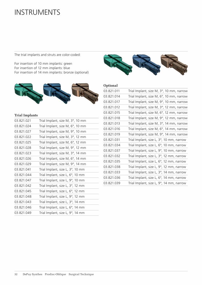
INSTRUMENTS
The trial implants and struts are color-coded:
For insertion of 10 mm implants: greenFor insertion of 12 mm implants: blueFor insertion of 14 mm implants: bronze (optional)
Trial Implants
03.821.021 Trial Implant, size M, 3°, 10 mm
03.821.024 Trial Implant, size M, 6°, 10 mm
03.821.027 Trial Implant, size M, 9°, 10 mm
03.821.022 Trial Implant, size M, 3°, 12 mm
03.821.025 Trial Implant, size M, 6°, 12 mm
03.821.028 Trial Implant, size M, 9°, 12 mm
03.821.023 Trial Implant, size M, 3°, 14 mm
03.821.026 Trial Implant, size M, 6°, 14 mm
03.821.029 Trial Implant, size M, 9°, 14 mm
03.821.041 Trial Implant, size L, 3°, 10 mm
03.821.044 Trial Implant, size L, 6°, 10 mm
03.821.047 Trial Implant, size L, 9°, 10 mm
03.821.042 Trial Implant, size L, 3°, 12 mm
03.821.045 Trial Implant, size L, 6°, 12 mm
03.821.048 Trial Implant, size L, 9°, 12 mm
03.821.043 Trial Implant, size L, 3°, 14 mm
03.821.046 Trial Implant, size L, 6°, 14 mm
03.821.049 Trial Implant, size L, 9°, 14 mm
Optional
03.821.011 Trial Implant, size M, 3°, 10 mm, narrow
03.821.014 Trial Implant, size M, 6°, 10 mm, narrow
03.821.017 Trial Implant, size M, 9°, 10 mm, narrow
03.821.012 Trial Implant, size M, 3°, 12 mm, narrow
03.821.015 Trial Implant, size M, 6°, 12 mm, narrow
03.821.018 Trial Implant, size M, 9°, 12 mm, narrow
03.821.013 Trial Implant, size M, 3°, 14 mm, narrow
03.821.016 Trial Implant, size M, 6°, 14 mm, narrow
03.821.019 Trial Implant, size M, 9°, 14 mm, narrow
03.821.031 Trial Implant, size L, 3°, 10 mm, narrow
03.821.034 Trial Implant, size L, 6°, 10 mm, narrow
03.821.037 Trial Implant, size L, 9°, 10 mm, narrow
03.821.032 Trial Implant, size L, 3°, 12 mm, narrow
03.821.035 Trial Implant, size L, 6°, 12 mm, narrow
03.821.038 Trial Implant, size L, 9°, 12 mm, narrow
03.821.033 Trial Implant, size L, 3°, 14 mm, narrow
03.821.036 Trial Implant, size L, 6°, 14 mm, narrow
03.821.039 Trial Implant, size L, 9°, 14 mm, narrow
Prodisc-Oblique Surgical Technique DePuy Synthes 33
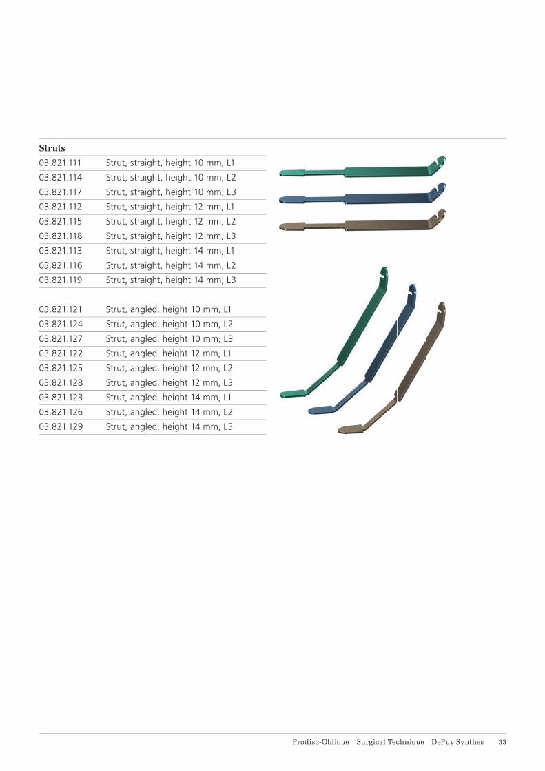
Struts
03.821.111 Strut, straight, height 10 mm, L1
03.821.114 Strut, straight, height 10 mm, L2
03.821.117 Strut, straight, height 10 mm, L3
03.821.112 Strut, straight, height 12 mm, L1
03.821.115 Strut, straight, height 12 mm, L2
03.821.118 Strut, straight, height 12 mm, L3
03.821.113 Strut, straight, height 14 mm, L1
03.821.116 Strut, straight, height 14 mm, L2
03.821.119 Strut, straight, height 14 mm, L3
03.821.121 Strut, angled, height 10 mm, L1
03.821.124 Strut, angled, height 10 mm, L2
03.821.127 Strut, angled, height 10 mm, L3
03.821.122 Strut, angled, height 12 mm, L1
03.821.125 Strut, angled, height 12 mm, L2
03.821.128 Strut, angled, height 12 mm, L3
03.821.123 Strut, angled, height 14 mm, L1
03.821.126 Strut, angled, height 14 mm, L2
03.821.129 Strut, angled, height 14 mm, L3
34 DePuy Synthes Prodisc-Oblique Surgical Technique
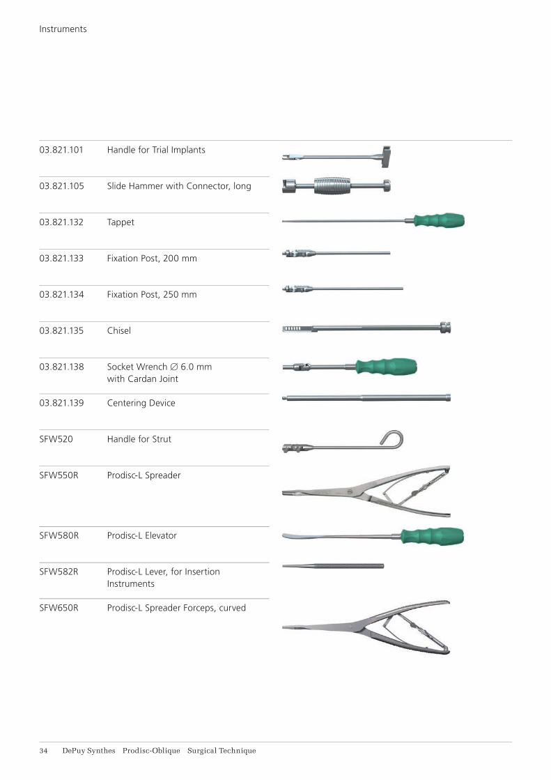
03.821.101 Handle for Trial Implants
03.821.105 Slide Hammer with Connector, long
03.821.132 Tappet
03.821.133 Fixation Post, 200 mm
03.821.134 Fixation Post, 250 mm
03.821.135 Chisel
03.821.138 Socket Wrench B 6.0 mm with Cardan Joint
03.821.139 Centering Device
SFW520 Handle for Strut
SFW550R Prodisc-L Spreader
SFW580R Prodisc-L Elevator
SFW582R Prodisc-L Lever, for Insertion Instruments
SFW650R Prodisc-L Spreader Forceps, curved
Instruments

Prodisc-Oblique Surgical Technique DePuy Synthes 35
Insertion instruments and distractors are color-coded. Color coding in the Vario Case indicates the instrument size:
Size M: Violet ringSize L: Yellow ring
03.821.143 Inserter, size M
03.821.145 Inserter, size L
03.821.151 Distractor, size M, height 10 mm
03.821.152 Distractor, size M, height 12 mm
03.821.153 Distractor, size M, height 14 mm
03.821.154 Distractor, size L, height 10 mm
03.821.155 Distractor, size L, height 12 mm
03.821.156 Distractor, size L, height 14 mm
03.821.157 Inserter for PE Inlay, size M
03.821.158 Inserter for PE Inlay, size L
03.821.136 Extraction Tool for Inserter
03.821.142 Guiding Device for Inserter, size M
03.821.144 Guiding Device for Inserter, size L
36 DePuy Synthes Prodisc-Oblique Surgical Technique
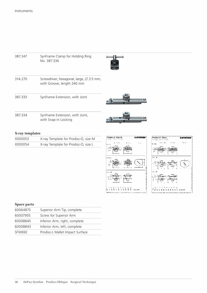
387.347 SynFrame Clamp for Holding Ring No. 387.336
314.270 Screwdriver, hexagonal, large, B 3.5 mm,with Groove, length 240 mm
387.333 SynFrame Extension, with Joint
387.334 SynFrame Extension, with Joint, with Snap-in Locking
X-ray templates
X000053 X-ray Template for Prodisc-O, size M
X000054 X-ray Template for Prodisc-O, size L
Spare parts
60064875 Superior Arm Tip, complete
60007955 Screw for Superior Arm
60008845 Inferior Arm, right, complete
60008843 Inferior Arm, left, complete
SFW692 Prodisc-L Mallet Impact Surface
Instruments
Prodisc-Oblique Surgical Technique DePuy Synthes 37
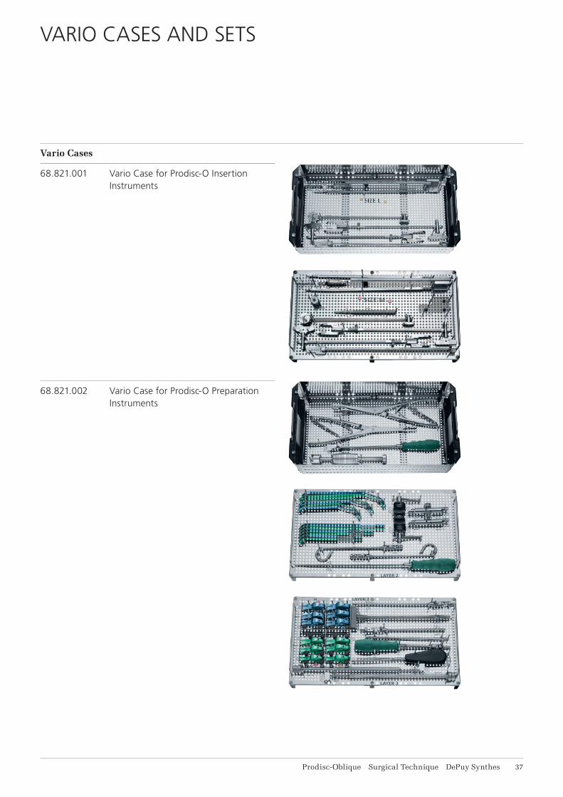
VARIO CASES AND SETS
Vario Cases
68.821.001 Vario Case for Prodisc-O Insertion Instruments
68.821.002 Vario Case for Prodisc-O Preparation Instruments
38 DePuy Synthes Prodisc-Oblique Surgical Technique
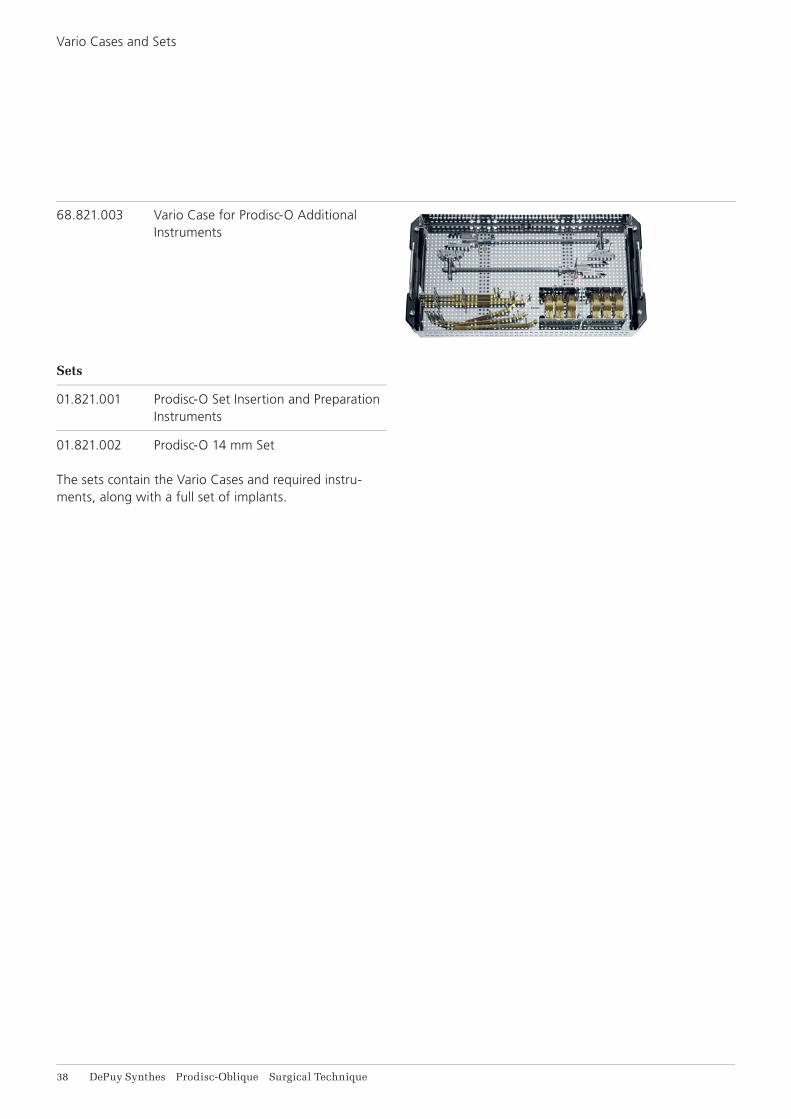
68.821.003 Vario Case for Prodisc-O Additional Instruments
Sets
01.821.001 Prodisc-O Set Insertion and Preparation Instruments
01.821.002 Prodisc-O 14 mm Set
The sets contain the Vario Cases and required instru-ments, along with a full set of implants.
Vario Cases and Sets
Prodisc-Oblique Surgical Technique DePuy Synthes 39
OTHER SYNTHES PRODUCTS FOR ACCESS, DISCECTOMY AND ENDPLATE PREPARATION
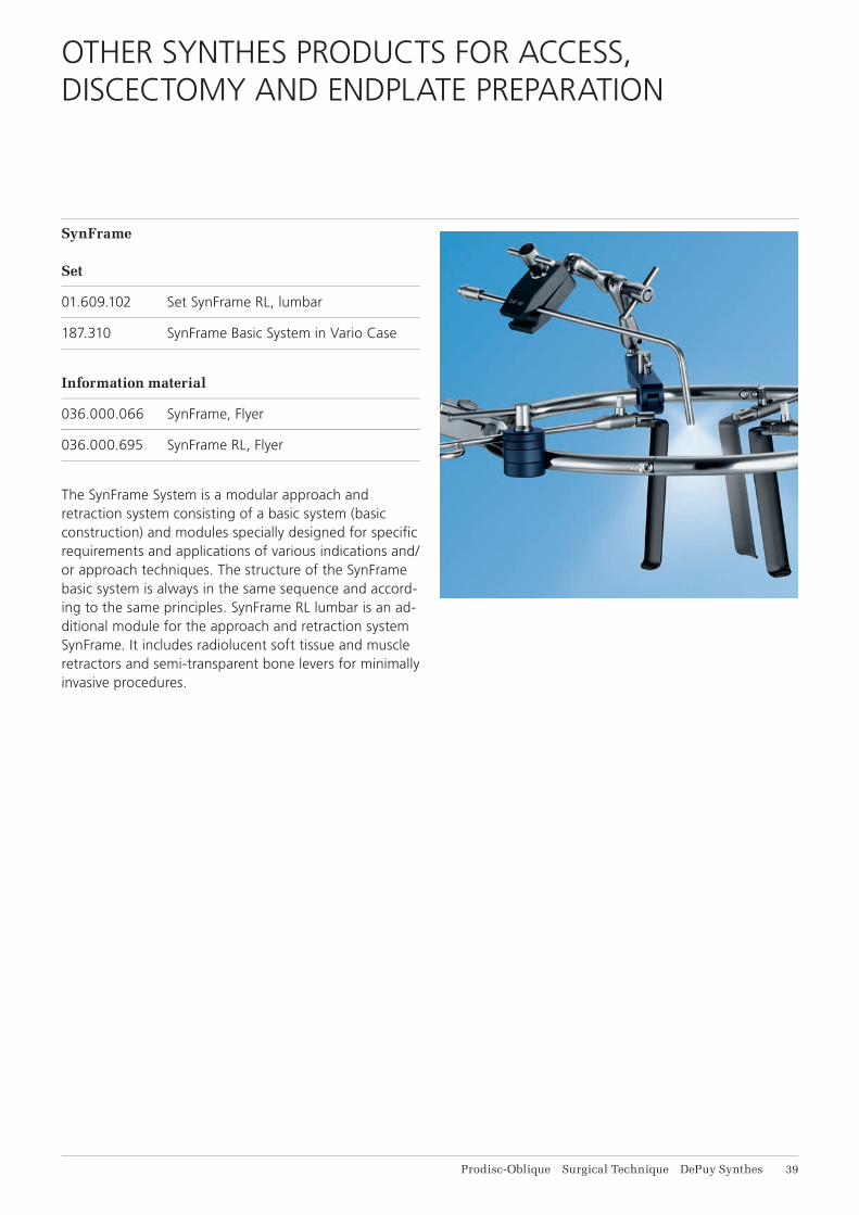
SynFrame
Set
01.609.102 Set SynFrame RL, lumbar
187.310 SynFrame Basic System in Vario Case
Information material
036.000.066 SynFrame, Flyer
036.000.695 SynFrame RL, Flyer
The SynFrame System is a modular approach and retraction system consisting of a basic system (basic construction) and modules specially designed for specifi c requirements and applications of various indications and/or approach techniques. The structure of the SynFrame basic system is always in the same sequence and accord-ing to the same principles. SynFrame RL lumbar is an ad-ditional module for the approach and retraction system SynFrame. It includes radio lucent soft tissue and muscle retractors and semi-transparent bone levers for minimally invasive procedures.
41 DePuy Synthes Prodisc-Oblique Surgical Technique
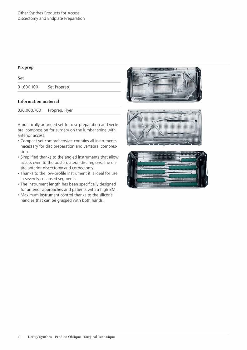
Proprep
Set
01.600.100 Set Proprep
Information material
036.000.760 Proprep, Flyer
A practically arranged set for disc preparation and verte-bral compression for surgery on the lumbar spine with anterior access.• Compact yet comprehensive: contains all instruments
necessary for disc preparation and vertebral compres-sion.
• Simplifi ed thanks to the angled instruments that allow access even to the posterolateral disc regions, the en-tire anterior discectomy and corpectomy.
• Thanks to the low-profi le instrument it is ideal for use in severely collapsed segments.
• The instrument length has been specifi cally designed for anterior approaches and patients with a high BMI.
• Maximum instrument control thanks to the silicone handles that can be grasped with both hands.
Other Synthes Products for Access, Discectomy and Endplate Preparation
Prodisc-Oblique Surgical Technique DePuy Synthes 41
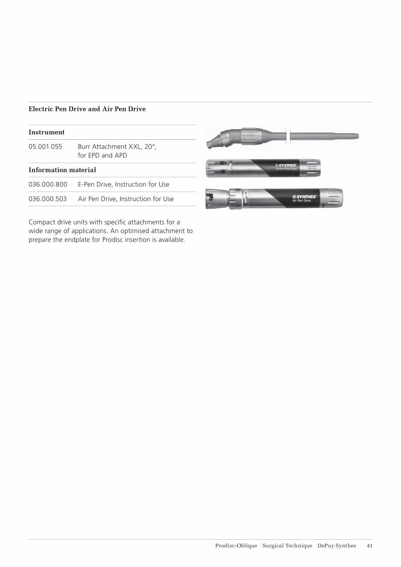
Electric Pen Drive and Air Pen Drive
Instrument
05.001.055 Burr Attachment XXL, 20°, for EPD and APD
Information material
036.000.800 E-Pen Drive, Instruction for Use
036.000.503 Air Pen Drive, Instruction for Use
Compact drive units with specifi c attachments for a wide range of applications. An optimised attachment to prepare the endplate for Prodisc insertion is available.

42 DePuy Synthes Prodisc-Oblique Surgical Technique
BIBLIOGRAPHY
Studies on Prodisc, the artificial intervertebral disc
Bae H, Kanim LEA, Sra P, Delamarter R, Kropf M (2004) Prodisc lumbar disc replacement vs fusion: preservation of motion and patient self assessment at 1-to-2-year follow up. Spine J 4 (5): S12
Barbagallo G.M.V., Certo F, Visocchi M, Sciacca G, Alba-nese V (2014) Double-level cervical total disc replace-ment for adjacent segment disease: is it a useful treat-ment? Description of late onset heterotopic ossifi cation and review of the literature. Eur Rev Med Pharmacol Sci 18 (1): 15–23
Berry JL, Moran JM, Berg WS, Steffee AD (1987) A mor-phometric study of human lumbar and selected thoracic vertebrae. Spine 12 (4): 362–367
Bertagnoli R, Marnay T, Mayer HM (2005) Total disc re-placement for degenerative disc disease in the lumbar spine. 2nd ed. Oberdorf, Synthes
Bertagnoli R, Yue JJ, Fenk-Mayer A, Eerulkar J, Emerson JW (2006) Treatment of symptomatic adjacent-segment degeneration after lumbar fusion with total disc arthro-plasty by using the Prodisc prosthesis: a prospective study with 2-year minimum follow up. J Neurosurg Spine 4(2): 91–97
Bertagnoli R, Yue JJ, Kershaw T, Shah RV, Pfeiffer F, Fenk-Mayer A, Nanieva R, Karg A, Husted DS, Emerson JW (2006) Lumbar total disc arthroplasty utilizing the ProDisc prosthesis in smokers versus nonsmokers: a pro-spective study with 2-year minimum follow-up. Spine 31(9): 992–997
Chung SS, Lee CS, Kang CS (2006) Lumbar total disc replacement using Prodisc II: a prospective study with a 2-year minimum follow-up. J Spinal Disord Tech (6): 411–415
Delamarter RB, Fribourg DM, Kanim LE, Bae H (2003) ProDisc artifi cial total lumbar disc replacement: introduc-tion and early results from the United States clinical trial. Spine 28(20): 167–175
Dvorak J, Panjabi MM, Chang DG, Theiler R, Grob D (1991) Functional radiographic diagnosis of the lumbar spine – fl exion-extension and lateral bending. Spine 16 (5): 562–571
Gilad I, Nissan M (1986) A study of Vertebra and Disc Geometric Relations of the Human Cervical and Lumbar Spine. Spine 11 (2): 154–157.
Hannibal M, Thomas DJ, Low J, Hsu KY, Zucherman J. (2007) Prodisc-L total disc replacement: a comparison of 1-level versus 2-level arthroplasty patients with a mini-mum 2-year follow-up. Spine 32(21): 2322–2326
Huang RC, Girardi FP, Cammisa Jr FP, Tropiano P, Marnay T (2003) Long-term fl exion-extension range of motion of the Prodisc total disc replacement. J Spinal Disord Tech 16(5): 435–440
Leivseth G, Braaten S, Frobin W, Brinckmann P (2006) Mobility of lumbar segments instrumented with a Pro-Disc II prosthesis: a two-year follow-up study. Spine 31(15): 1726–1733
Pearcy M, Portek I, Shepherd J (1984) Three-dimensional X-ray analysis of normal movement in the lumbar spine. Spine 9 (3): 294–297
Pearcy MJ, Tibrewal SB (1984) Axial rotation and lateral bending in the normal lumbar spine measured by three-dimensional radiography. Spine 9 (6): 582–591
Siepe CJ, Mayer HM, Wiechert K, Korge A (2006) Clini-cal results of total lumbar disc replacement with ProDisc II: three-year results for different indications. Spine 31(17): 1923–1932
Tropiano P, Huang RC, Girardi FP, Marnay T (2003) Lum-bar disc replacement: preliminary results with Prodisc® II after a minimum follow-up period of 1 year. J Spinal Dis-ord Tech 16 (4): 362–368

Prodisc-Oblique Surgical Technique DePuy Synthes 43
Tropiano P, Huang RC, Girardi FP, Cammisa FP, Marnay T (2005) Lumbar total disc replacement. Seven to Eleven-Year Follow-Up. J Bone Joint Surg Am 87 (3): 490–496
White AA, Panjabi MM (1990): Clinical biomechanics of the spine. 2nd. ed. Philadelphia, Lippincott.
Yue JJ, Bertagnoli R, Husted DS, Shah R, Kershaw T (2004) The treatment of disabling multilevel lumbar dis-cogenic low back pain with total disc arthroplasty utiliz-ing the Prodisc prosthesis: a prospective study with 2-year minimum follow up. Spine J 4 (5): 49–50
Zigler JE (2003) Clinical results with ProDisc: European experience and U.S. investigation device exemption study. Spine 28 (20): 163–166
Zigler JE, Burd TA, Vialle EN, Sachs BL, Rashbaum RF, Ohnmeiss DD (2003) Lumbar spine arthroplasty: early re-sults using the ProDisc II: a prospective randomized trial of arthroplasty versus fusion. J Spinal Disord Tech 16(4): 352–361
Zigler J, Sachs B, Rashbaum R, Ohnmeiss D (2004) Total disc replacement using ProDisc 12-to-24–month follow up results of a prospective randomized comparison to fusion. Spine J 4 (5): 25–26
Zigler J, Delamarter R, Spivak JM, Linovitz RJ, Danielson GO 3rd, Haider TT, Cammisa F, Zucherman J, Balderston R, Kitchel S, Foley K, Watkins R, Bradford D, Yue J, Yuan H, Herkowitz H, Geiger D, Bendo J, Peppers T, Sachs B, Girardi F, Kropf M, Goldstein J (2007) Results of the pro-spective, randomized, multicenter Food and Drug Ad-ministration investigational device exemption study of the Prodisc-L total disc replacement versus circumferen-tial fusion for the treatment of 1-level degenerative disc disease. Spine 32(11): 1155–1162


0123
Synthes GmbHEimattstrasse 34436 OberdorfSwitzerlandTel: +41 61 965 61 11Fax: +41 61 965 66 00www.depuysynthes.com
This publication is not intended for distribution in the USA.
Not all products are currently available in all markets.
All surgical techniques are available as PDF files at www.depuysynthes.com/ifu ©
DeP
uy S
ynth
es S
pine
, a d
ivis
ion
of S
ynth
es G
mbH
. 201
5.
All
right
s re
serv
ed.
036.
000.
698
DS
EM
/SP
N/0
215/
0274
12
/15


![Lumbar foraminal neuropathy: an update on non-surgical ...€¦ · Foraminal stenosis is common in the elderly population [1], characterized by narrowing of the bony exit of the nerve](https://img.pdfslide.us/doc/110x75/6062a38e6344726cad414763/lumbar-foraminal-neuropathy-an-update-on-non-surgical-foraminal-stenosis-is.jpg)