Embed Size (px)
Citation preview

i
TERMS OF REFERENCE FOR GUYANA HINTERLAND STAND-ALONE SOLAR PV INSTALLATIONS
IMPLEMENTED UNDER THE USAID IHFI GUYANA
CONTRACT No. EPP-I-00-03-00008-00, TASK ORDER 07.
Prepared by:
Tetra Tech
4601 N. Fairfax Drive
Suite 601
Arlington, VA 22203
USA
Tel: +1-703-387-2134
Fax: +1-703-387-2160

ii
Table of Contents 1. Background ....................................................................................................................................... 1
Solar radiation availability..................................................................................................................... 2
2. Solar System Design .......................................................................................................................... 4
Design 1 – PV System for One Vaccine Refrigerator and Eight Light Bulbs .......................................... 4
HOMER Input Parameters ......................................................................................................................... 4
HOMER Simulation Results ....................................................................................................................... 5
Design 1 - HOMER Input and Output Summary ........................................................................................ 5
Design 2 – Solar PV for Eight Light Bulbs Load ...................................................................................... 9
HOMER Inputs ........................................................................................................................................... 9
HOMER Simulation Results ....................................................................................................................... 9
Design 2 - HOMER Input and Output Summary ...................................................................................... 10
Design 1 – Single Line Diagram for Solar Vaccine Refrigerator and Light System .............................. 14
Design 2 - Single Line Diagram for Solar Light System ........................................................................ 15
3. Solar System Bid Specifications: ..................................................................................................... 16
4. Bidder’s Data Sheets ....................................................................................................................... 22
A. IHFI Guyana PV Installation: Bidder’s Response ......................................................................... 22
B. System Cost Data Sheet .............................................................................................................. 23
C. Bill of Materials Data Sheet ........................................................................................................ 23
Appendix A; Site drawings- Proposed sighting of solar system .............................................................. 24
Appendix B: Health Facility Floor Plan – Solar Systems Wiring Diagram ............................................ 28
Appendix C: Load and energy requirement for health clinics ................................................................ 34
1
Solar Electrification for Hinterland Health Facilities in Guyana
Terms of Reference for Solar Systems Procurement
1. Background
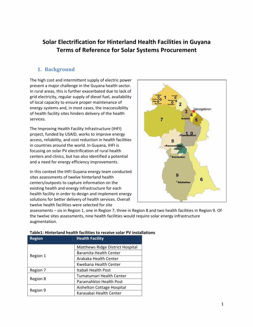
The high cost and intermittent supply of electric power present a major challenge in the Guyana health sector. In rural areas, this is further exacerbated due to lack of grid electricity, regular supply of diesel fuel, availability of local capacity to ensure proper maintenance of energy systems and, in most cases, the inaccessibility of health facility sites hinders delivery of the health services.
The Improving Health Facility Infrastructure (IHFI) project, funded by USAID, works to improve energy access, reliability, and cost reduction in health facilities in countries around the world. In Guyana, IHFI is focusing on solar PV electrification of rural health centers and clinics, but has also identified a potential and a need for energy efficiency improvements.
In this context the IHFI Guyana energy team conducted sites assessments of twelve hinterland health centers/outposts to capture information on the existing health and energy infrastructure for each health facility in order to design and implement energy solutions for better delivery of health services. Overall twelve health facilities were selected for site assessments – six in Region 1, one in Region 7, three in Region 8 and two health facilities in Region 9. Of the twelve sites assessments, nine health facilities would require solar energy infrastructure augmentation. Table1: Hinterland health facilities to receive solar PV installations
Region Health Facility
Region 1
Matthews Ridge District Hospital
Baramita Health Center
Arakaka Health Center
Kwebana Health Center
Region 7 Itabali Health Post
Region 8 Tumatumari Health Center
Paramahktoi Health Post
Region 9 Aishelton Cottage Hospital
Karasabai Health Center
2
The key findings from the site assessments are:
a. Most of the systems are either single-panel or two-panel systems, so there is no critical mass or redundancy available.
b. Battery storage was not properly designed – one battery per system is insufficient when several days of overcast skies are typical during the rainy season.
c. Electrical circuitry was not properly designed – no circuit breakers or protection devices were installed, so the solar PV system components have failed due to various abnormal electrical conditions such as overvoltage, high current from short circuits, and completely drained batteries
d. Batteries were not maintained, so they cannot hold the charge. e. Solar panels are improperly installed (inside rooms, overlapping on roofs), so do not reach
their potential performance. f. Poor electrical installations result in burned out sockets, so solar PV cannot be fully used.
The objective of the IHFI Guyana solar project is to develop a model design, installation and maintenance program for solar systems primarily to achieve the following key goals:
Develop standard design criterion for solar PV systems.
Design large capacity systems to be able to withstand weather anomalies.
Install systems with adequate controls and protections.
Develop a battery maintenance program, including hands-on training, to provide maintenance
training to local technicians.
Solar radiation availability Guyana is located close to the equator; approximately bounded between Latitudes 2O N to 9O N. Given the latitude, the average daily solar radiation over the targeted solar installations sites is likely to be high. However, the following tables show that the available irradiation is not as high as expected. This is due to the fact that these areas are typical of dense rain forests and experience frequent cloud obstruction. This is evidenced from the fact that the diffuse radiation is more than 40% of the total global horizontal radiation for each site. According to local sources during our sites assessment, the overcast sky conditions persist for several days, especially during the rainy seasons. Note that in Guyana the rainy season extends for over six months. It is important that the battery capacity and solar panels for each system are sized appropriately to withstand weather anomalies.

3
Table 2A: Global Horizontal Radiation (kWh/m2/day)
Region Health Facility Loacation
Jan Feb Mar Apr May Jun Jul Aug Sept Oct Nov Dec Average
Region 1
Matthews Ridge, Baramita, Arakaka & Kwebana
4.61 5.03 5.47 5.46 4.94 4.76 5.05 5.45 5.69 5.41 4.78 4.48 5.09
Region 7 Itabali 4.36 4.38 4.28 4.43 4.34 4.93 5.36 5.23 5.18 4.98 4.73 4.33 4.71
Region 8 Tumatumari 4.34 4.55 4.82 4.76 4.4 4.51 4.92 5.31 5.66 5.42 4.79 4.29 4.81
Paramahktoi 4.93 5.22 5.52 5.24 4.76 4.82 5.01 5.38 5.88 5.7 5.23 4.87 5.21
Region 9 Aishelton 5.04 5.15 5.21 4.93 4.38 4.51 4.76 5.21 5.75 5.71 5.26 4.99 5.07
Karasabai 4.93 5.22 5.52 5.24 4.76 4.82 5.01 5.38 5.88 5.7 5.23 4.87 5.21
Source: http://eosweb.larc.nasa.gov/cgi-bin
Table 2B: Diffuse Horizontal Radiation (kWh/m2/day)
Region Health Facility Loacation
Jan Feb Mar Apr May Jun Jul Aug Sept Oct Nov Dec Average
Region 1
Matthews Ridge, Baramita, Arakaka & Kwebana
1.87 2.03 2.17 2.25 2.21 2.15 2.14 2.17 2.14 2 1.89 1.81 2.07
Region 7 Itabali 2.31 2.37 2.32 2.11 1.86 1.57 1.5 1.84 2.15 2.34 2.32 2.28 2.08
Region 8 Tumatumari 1.98 2.14 2.28 2.3 2.2 2.11 2.1 2.16 2.16 2.06 1.96 1.91 2.11
Paramahktoi 1.93 2.09 2.21 2.24 2.15 2.05 2.05 2.12 2.11 2.01 1.91 1.87 2.06
Region 9 Aishelton 2 2.16 2.28 2.24 2.12 2.02 2.02 2.11 2.15 2.06 1.98 1.93 2.09
Karasabai 1.94 2.09 2.21 2.24 2.15 2.05 2.05 2.12 2.12 2.02 1.92 1.87 2.06
Source: http://eosweb.larc.nasa.gov/cgi-bin
Table 2C: Diffuse Radiation as % of Global Horizontal Radiation
Region Health Facility Loacation Diffuse Radiation % of
Global Horizontal radiation
Region 1 Matthews Ridge, Baramita, Arakaka & Kwebana 41%
Region 7 Itabali 44%
Region 8 Tumatumari 44%
Paramahktoi 40%

4
Region 9 Aishelton 41%
2. Solar System Design
Based on site assessment of the health clinics, the electrical loads to be connected to the solar PV systems are proposed for two cases: (a) one vaccine refrigerator and eight 20 W CFL light bulbs and (b) eight 20 W CFL light bulbs. Shown in the following table are the loads and energy requirements for one health center that received an on-site assessment. Electrical loads and energy requirements are provided for all nine facilities in Appendix C.
Table 3: Electrical Loads Served by Solar PV System
Based on the above load and energy requirements, two standard designs for the solar PV systems are proposed:
Design 1 – PV System for One Vaccine Refrigerator and Eight Light Bulbs HOMER Input Parameters Daily Energy requirement: 1702 Wh/day
Battery Input: U S Battery, 6V, 305 Amp-hr.
System Voltage: 24 Volts
Baramita Health Center (Region 1)Front Building Qty CFL Bulb Total Total Watt-hours
Lighting Load (AC Load) Duration Hrs Watts Watts
Exterior light 7 p.m. to 5 a.m. 10 1 20 20 200
Staff quarter 6 1 20 20 120
Outpatient Room 5 1 20 20 100
Patient ward/Malarial room 7 p.m. to 5 a.m. 10 1 20 20 200
Delivery room 6 1 20 20 120
Store room/Vacc. Ref room 4 1 20 20 80
Medicine Storage 5 1 20 20 100
Corridor Light 7 p.m. to 5 a.m. 10 1 20 20 200
Other Plug Loads (15% of 1480 Whr) 222
Vaccine Refrigerator Load (DC Load) VR Watts
One Vaccine Refrigerator 6 1 60 60 360
Total 220 1702
Rear Building Qty CFL Bulb Total Total Watt-hours
AC Load Duration Hrs Watts Watts
Exterior light 7 p.m. to 5 a.m. 10 1 20 20 200
Patient ward 7 p.m. to 5 a.m. 10 1 20 20 200
Malaria Lab 5 1 20 20 100
Other indoor areas 6 5 20 100 600
Other Plug Loads (15% of 1100 Whr) 165
Total 160 1265
Operating Hours
Operating Hours

5
Solar radiation grid: Latitude 5o N and 59o W (Solar resource obtained from inbuilt database)
Loss factors
a. Incident Angle Modifier Loss: 3% b. Temperature loss: 10% c. Charge controller loss 5% d. Array mismatch loss: 1.5% e. Wire loss: 2% f. Dust irradiance loss: 1.2%
g. Inverter loss: 5% h. Battery loss: 20%
Total loss factor: (1-a)*(1-b)*(1-c)*(1-d)*(1-e)*(1-f)*(1-g) *(1-h)= 60.1%
HOMER Simulation Results
Design 1 - HOMER Input and Output Summary SYSTEM DESIGN CTITEION: PV array and battery bank size to maintain Battery Depth of Discharge (DOD) of 50% and no more than twice in a month the DOD reaches 60%:

6
HOMER Output:
A. PV array size: 1.25 kW B. Battery Bank: 305 Amp-hr, 24 Voltage system
Sensitivity case
Maximum Annual Capacity Shortage: 5 %
System architecture
PV Array 1.25 kW
Battery 4 USB US-305
Inverter 0.6 kW
Energy
Component
Production Fraction
(kWh/yr)
PV array 1,244 100%
Total 1,244 100%
Load
Consumption Fraction
(kWh/yr)
AC primary load 621 100%
Total 621 100%
Quantity Value Units
Excess electricity 502 kWh/yr
Unmet load 0.000000415 kWh/yr
Capacity shortage 0.00 kWh/yr
Renewable fraction 1.000

7
PV
Quantity Value Units
Rated capacity 1.25 kW
Mean output 0.142 kW
Mean output 3.41 kWh/d
Capacity factor 11.4 %
Total production 1,244 kWh/yr
Quantity Value Units
Minimum output 0.00 kW
Maximum output 0.954 kW
PV penetration 200 %
Hours of operation 4,380 hr/yr
Levelized cost 0.894 $/kWh
Battery
Quantity Value
String size 4
Strings in parallel 1
Batteries 4
Bus voltage (V) 24
Quantity Value Units
Nominal capacity 7.32 kWh
Usable nominal capacity 4.39 kWh
Autonomy 61.9 hr
Lifetime throughput 3,856 kWh

8
Battery wear cost 0.348 $/kWh
Average energy cost 0.000 $/kWh
Quantity Value Units
Energy in 446 kWh/yr
Energy out 358 kWh/yr
Storage depletion 0.0577 kWh/yr
Losses 88.2 kWh/yr
Annual throughput 400 kWh/yr
Expected life 9.63 yr
Converter
Quantity Inverter Rectifier Units
Capacity 0.600 0.00 kW
Mean output 0.071 0.00 kW
Minimum output 0.013 0.00 kW

9
Maximum output 0.120 0.00 kW
Capacity factor 11.8 0.0 %
Quantity Inverter Rectifier Units
Hours of operation 8,760 0 hrs/yr
Energy in 654 0 kWh/yr
Energy out 621 0 kWh/yr
Losses 33 0 kWh/yr
Design 2 – Solar PV for Eight Light Bulbs Load
HOMER Inputs Daily Energy requirement: 1265 Wh/day Battery Input: Trojan 105 Battery, 6V, 225 Amp-hr.
System Voltage: 24 Volts
Solar radiation grid: Latitude 5o N and 59o W (Solar resource obtained from inbuilt database)
Loss factors
a. Incident Angle Modifier Loss: 3% b. Temperature loss: 10% c. Charge controller loss 5% d. Array mismatch loss: 1.5% e. Wire loss: 2% f. Dust irradiance loss: 1.2%
g. Inverter loss: 5% h. Battery loss: 20%
Total loss factor: (1-a)*(1-b)*(1-c)*(1-d)*(1-e)*(1-f)*(1-g) *(1-h)= 60.1%
HOMER Simulation Results

10
Design 2 - HOMER Input and Output Summary
SYSTEM DESIGN CTITEION: PV array and battery bank size to maintain Battery Depth of Discharge (DOD) of 50% and no more than twice in a month the DOD reaches 60%:
HOMER Output:
A. PV array size: 1 kW B. Battery Bank: 225 Amp-hr, 24 Voltage system
Sensitivity case
Maximum Annual Capacity Shortage: 5 %
System architecture
PV Array 1 kW
Battery 4 Trojan T-105
Inverter 0.4 kW

11
Energy
Component
Production Fraction
(kWh/yr)
PV array 995 100%
Total 995 100%
Load
Consumption Fraction
(kWh/yr)
AC primary load 462 100%
Total 462 100%
Quantity Value Units
Excess electricity 463 kWh/yr
Unmet load 0.000000378 kWh/yr
Capacity shortage 0.00 kWh/yr
Renewable fraction 1.000
PV
Quantity Value Units
Rated capacity 1.00 kW
Mean output 0.114 kW
Mean output 2.73 kWh/d
Capacity factor 11.4 %
Total production 995 kWh/yr
Quantity Value Units

12
Minimum output 0.00 kW
Maximum output 0.763 kW
PV penetration 216 %
Hours of operation 4,380 hr/yr
Levelized cost 0.894 $/kWh
Battery
Quantity Value
String size 4
Strings in parallel 1
Batteries 4
Bus voltage (V) 24
Quantity Value Units
Nominal capacity 5.40 kWh
Usable nominal capacity 3.78 kWh
Autonomy 71.7 hr
Lifetime throughput 3,380 kWh
Battery wear cost 0.385 $/kWh
Average energy cost 0.000 $/kWh
Quantity Value Units
Energy in 310 kWh/yr
Energy out 264 kWh/yr
Storage depletion 0.485 kWh/yr
Losses 45.5 kWh/yr
Annual throughput 286 kWh/yr

13
Expected life 10.0 yr
Converter
Quantity Inverter Rectifier Units
Capacity 0.400 0.00 kW
Mean output 0.053 0.00 kW
Minimum output 0.010 0.00 kW
Maximum output 0.089 0.00 kW
Capacity factor 13.2 0.0 %
Quantity Inverter Rectifier Units
Hours of operation 8,760 0 hrs/yr
Energy in 486 0 kWh/yr
Energy out 462 0 kWh/yr
Losses 24 0 kWh/yr

14
Design 1 – Single Line Diagram for Solar Vaccine Refrigerator and Light System

15
Design 2 - Single Line Diagram for Solar Light System
All fuses and wires shall be sized according to the NEC 2011 of the United States or equivalent in Guyana and the installation manual of the equipment.

16
3. Solar System Bid Specifications:
Tetra Tech is soliciting solar PV systems for nine health clinics on a turnkey basis, including the supply of complete PV systems, installation of the systems at the respective sites and the commissioning of the systems. Two standard designs consisting of nine systems of 1250 Watts each and three systems of 1000 Watts each will supplied by the vendor.
Table 4: Number and Capacity for Nine Hinterland Health Facilities
Hinterland Region
Number of Systems
Solar PV System Capacity
Recipient Health Facilities
1 One 1250 W Matthews Ridge District Hospital,
1 Two One 1250 W and One 1000 W
systems
Baramita Health Center
1 One 1250 W Arakaka Health Center
1 One 1250 W Kwebana Health Center
7 One 1250 W Itabali Health Post
8 One 1250 W Tumatumari Health Post
8 One 1250 W Paramahktoi Health Post
9 Three One 1250 W and Two 1000 W
systems
Aishelton Cottage Hospital
9 One 1250 W Karasabai Health Center
A. General Specifications
1. A successful Bidder, herein referred as Contractor, shall provide upto nine 1250 W and three 1000 W off-grid (stand-alone) photovoltaic systems. All the solar panels shall be mode of crystalline silicon solar cells. All systems shall be fully operational turnkey installations. The systems will be installed at a number of health facilities specified in the Table 4. A Contractor shall submit the bid for installation of solar systems at health facilities for at least one Region as shown in Table 4. However, a Contractor is encouraged to submit bid for turnkey installation of the systems for more than one Region.
2. Contractor shall make their own assessment of the sites and suggest a suitable location for installation of the roof-top PV systems for each site. The location chosen for system installation for each site shall be approved by a Tetra Tech representative. Note that tentative sighting of the systems for each site is shown in Appendix A based on Tetra Tech’s assessment of the sites. The Bidder may assume the following site conditions:

17
a. According to Tetra Tech’s assessment of the health facilities, all the facilities have adequate
unshaded rooftop space. The Contractor shall make own assessments for enough space available for unshaded array: The array will be installed where shading is avoided from 9am – 3pm “solar time” each day of the year. This will be verified with a Solar Pathfinder, Solmetric SunEye, or equivalent during the pre-installation and again during the acceptance test.
3. The installed system must meet applicable national standards and codes. Safety signage and
labeling should be mounted on the system according to the US National Electrical Code 690 or equivalent code in Guyana and applicable building codes of Guyana. Tetra Tech will provide plastic laminated safety signage placards for each installation. Contractor shall install the same at designated locations as per instructions.
4. PV modules must meet the requirements of IEC 61215 standards. Contractor shall provide PV module efficiency at 1000 W/m
2 and 200 W/m
2 solar radiation level. For each site PV modules
must be procured for same make (manufacture) and same wattage rating.
5. Contractor shall supply battery capacity of 305 Amp-hrs for the 1250Wdc PV systems and 225 Amp-hr for the 1000 Wdc system.
6. Contractor shall design the system to a 24 Volt system. Multiple batteries should be connected only in series.
7. Lead-acid batteries of standard makes – either flooded or gel type will be supplied by the Contractor. Manufactures data sheets containing battery performance specifications shall be included in the bid. For each site batteries must be procured for same make (manufacture) and same amp-hr rating.
8. The battery bank at each site shall be placed in a secure location and housed within a ventilated metal frame enclosure. At least 1½ feet space between the battery terminals and enclosure ceiling shall be provided to ensure easy excess for maintenance. The metal frame enclosure design should ensure that the battery terminals or leads do not contact the enclosure. The bottom mesh surface of the metal farm enclosure shall be elevated from the floor/ground by 6 inches.
B. PV System Mechanical Design Specifications
1. The installed system shall include all hardware required for assembling the photovoltaic array, balance of system components, and structural attachments to a roof-top structure.
2. The PV array shall be installed at the roof-top slope which is approximately 20 degrees, and a southern orientation within south east to southwest +/-15 degrees of true south.
3. The PV array mounting structure, including modules, and balance of system components shall be designed to withstand wind loads of at least 60 mph (3-second gust).
4. Adequate spacing, about 4 to 6 inches, between the rooftop surface and PV mount frame shall be maintained to allow air circulation to cool the module back sheet.
5. Array mounting hardware supplied shall be compatible with the site considerations and environment. Mounting structures of anodized aluminum material shall be provided. Mechanical hardware shall be durable and corrosion resistant. The use of ferrous metals (including but not limited to painted or plated steel), dissimilar metals in contact, or any wood or plastic components is not allowed. Materials may require approval before commencing construction.
6. Special attention shall be paid to minimizing the risk from exposed fasteners, sharp edges, and potential damage to the modules or support structure. All potentially hazardous hardware shall be protected or shielded for safety.
7. Mechanical hardware, conduit, and other equipment shall be concealed beneath and/or behind the array. Contractor shall provide combiner boxes if required.

18
8. The array layout shall be consistent with the ordering (and labeling) of source circuits in the array combiner boxes. Accessibility to perform array troubleshooting and maintenance is required by allowing access to the back of the array.
9. The PV systems will be installed at health clinics, therefore staff and patient safety is critical. Contractor must minimize the risk of vandalism, theft and personal injury in the installation and operation of the system. Therefore, designs will provide proper layout, enclosures, shields and housings to protect health facility occupants in their daily activities.
C. PV System Electrical Design Specifications
1. All work shall be done in accordance with the US National Electrical Code 2011 or equivalent in Guyana and the latest edition of the Guyana Building Code.
2. The PV array nameplate rating (at Standard Test Conditions, STC) shall be no less than 1250 Wdc and 1000 Wdc at STC. Contractor shall provide PV module rating at 200 W/m
2 solar
radiation level. This nameplate capacity shall not exceed 115% of the power rating of its connected charge controller.
3. All PV modules shall have connectors with locking clips, such as the Multi-Contact Type 4 with PV-SSH4 safety lock clip (or equivalent) that requires a tool to unlock.
4. A grounding electrode (or multiple electrodes if required by NEC) shall be installed for the arrays.
5. All inverters shall be commercially-available models certified to UL or equivalent standard presently under active manufacture, and must include ground-fault protection with a visible indicator. The inverter size shall be at least 125% the size of its total connected load. Furthermore the charging component of the inverter shall be able to recharge the batteries at C/10.
6. All charge controllers shall be commercially-available models presently under active manufacture, and they shall be listed, must include ground-fault protection with a visible indicator. The charge controller shall be of the same brand as the inverter/charger.
7. All necessary communication accessories and sensors for the proper functioning of the Inverter/Charger and Charge Controller shall be provided. Charge controller and inverter/charge shall of same make.
8. Charge Controller and the Inverter/Charger shall be installed at the same location or within close proximity.
9. Each series source circuit of PV modules shall be protected by an inline over current protective device (OCPD).
10. The Contractor shall provide two DC plug sockets and two AC plug sockets at each site. Each AC plug socket shall be provided with a circuit breaker to trip to limit plug load (appliance or gadget) rating to maximum 100 W.
11. All outdoor wiring must be listed to a temperature rating of 90°C in wet locations, and it shall be listed as sunlight resistant where run outdoors and outside of conduit. All AC wiring shall be ducted in metal conduits. DC wiring can be ducted in PVC conduits.
12. Outdoor-rated, visible-break lockable disconnects shall be installed on each set of current-carrying conductors entering or leaving the array area.
13. When wiring the PV panel and battery to the charge controller, breaker(s) shall be connected at both sides – PV module to charge controller and charge controller to battery as per NEC standards.
14. For each location, Contractor shall supply eight 20W CFL bulbs of standard make. Each lighting fixture shall be supplied with one 20 W CFL bulb. In addition, sixteen 20W CFL bulbs in sealed package shall be supplied for each site as spare bulbs.
15. Voltage drop in each of these paths shall not exceed 1% at rated capacity:
19
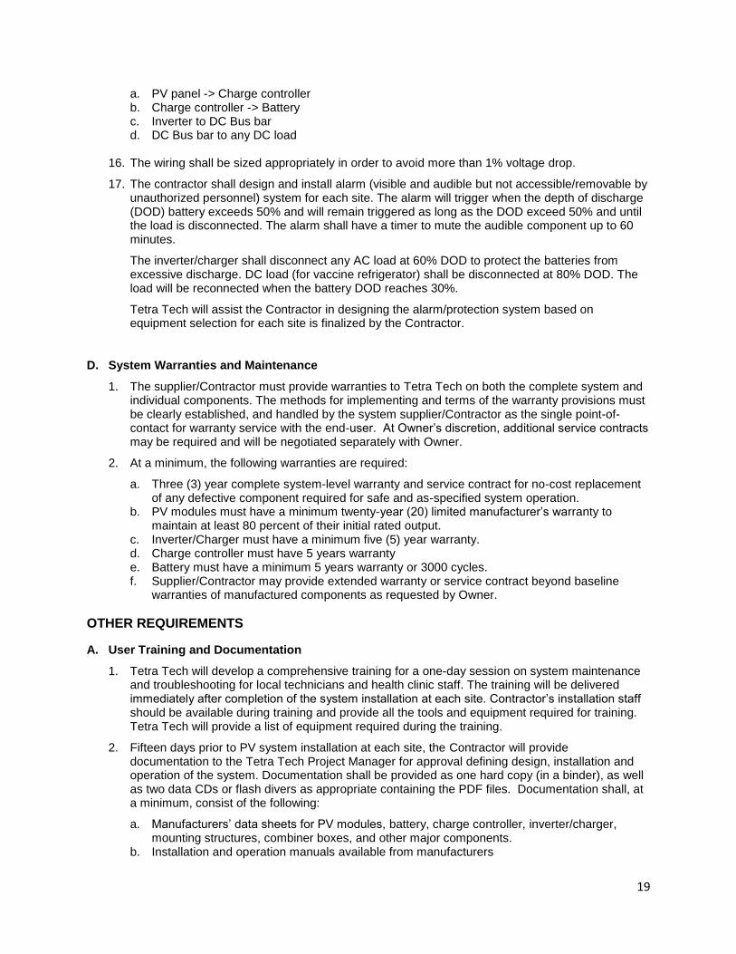
a. PV panel -> Charge controller b. Charge controller -> Battery c. Inverter to DC Bus bar d. DC Bus bar to any DC load
16. The wiring shall be sized appropriately in order to avoid more than 1% voltage drop.
17. The contractor shall design and install alarm (visible and audible but not accessible/removable by unauthorized personnel) system for each site. The alarm will trigger when the depth of discharge (DOD) battery exceeds 50% and will remain triggered as long as the DOD exceed 50% and until the load is disconnected. The alarm shall have a timer to mute the audible component up to 60 minutes.
The inverter/charger shall disconnect any AC load at 60% DOD to protect the batteries from excessive discharge. DC load (for vaccine refrigerator) shall be disconnected at 80% DOD. The load will be reconnected when the battery DOD reaches 30%.
Tetra Tech will assist the Contractor in designing the alarm/protection system based on equipment selection for each site is finalized by the Contractor.
D. System Warranties and Maintenance
1. The supplier/Contractor must provide warranties to Tetra Tech on both the complete system and individual components. The methods for implementing and terms of the warranty provisions must be clearly established, and handled by the system supplier/Contractor as the single point-of-contact for warranty service with the end-user. At Owner’s discretion, additional service contracts may be required and will be negotiated separately with Owner.
2. At a minimum, the following warranties are required:
a. Three (3) year complete system-level warranty and service contract for no-cost replacement of any defective component required for safe and as-specified system operation.
b. PV modules must have a minimum twenty-year (20) limited manufacturer’s warranty to maintain at least 80 percent of their initial rated output.
c. Inverter/Charger must have a minimum five (5) year warranty. d. Charge controller must have 5 years warranty e. Battery must have a minimum 5 years warranty or 3000 cycles. f. Supplier/Contractor may provide extended warranty or service contract beyond baseline
warranties of manufactured components as requested by Owner.
OTHER REQUIREMENTS
A. User Training and Documentation
1. Tetra Tech will develop a comprehensive training for a one-day session on system maintenance and troubleshooting for local technicians and health clinic staff. The training will be delivered immediately after completion of the system installation at each site. Contractor’s installation staff should be available during training and provide all the tools and equipment required for training. Tetra Tech will provide a list of equipment required during the training.
2. Fifteen days prior to PV system installation at each site, the Contractor will provide documentation to the Tetra Tech Project Manager for approval defining design, installation and operation of the system. Documentation shall be provided as one hard copy (in a binder), as well as two data CDs or flash divers as appropriate containing the PDF files. Documentation shall, at a minimum, consist of the following:
a. Manufacturers’ data sheets for PV modules, battery, charge controller, inverter/charger, mounting structures, combiner boxes, and other major components.
b. Installation and operation manuals available from manufacturers

20
c. Warranty information and user manuals for all major system components d. Single-line electrical schematic of the as-built system e. Comprehensive guide covering basics of system operation for the specific installed system:
i. How to operate equipment displays ii. How to safely disconnect and reconnect system iii. Basic tests to ensure system is operating correctly iv. Maintenance allowed by non-qualified personnel v. Proper safety procedures when working around system
3. A copy of all documentation shall be provided to the Ministry of Health and Guyana Energy
Agency in electronic format for review and approval.
4. Along with the bid, the Contractor shall submit “Bidder’s Response Data Sheet” provided in Section 4 of this solicitation.
B. Inspections and Acceptance Testing
1. The system components shall be certified to acceptable standards including UL and IEC standards and must be inspected and approved by the Tetra Tech’s authorized representative.
2. Bidder shall ensure that all project specifications have been met. Tetra Tech will verify compliance through a site inspection and acceptance tests. The system installer/Contractor shall be available and present for the acceptance tests, which will be scheduled with reasonable advance notice (notwithstanding delays due to weather). Acceptance testing will verify that the system and equipment specified in the bid was installed in a safe and code-compliant manner, and is operating properly under all conditions.
3. All charges incurred as a result of non-compliance on the part of the Contractor shall be borne entirely by the Contractor and shall be deducted from the final payment.
4. Acceptance testing forms will be made available to the selected bidders as early as possible after award but no later than before system construction begins.
C. Payment Schedule
1. Contractor shall provide installed cost (in Guyanese Dollars) per system per site including all taxes and duties as per the system installed cost data sheet in Section 4.
2. Payment can be claimed for each site. Payments will be made according to the following schedule, with documentation as noted:
a. 20% of contracted amount: i. Issuance of Notice to Proceed ii. Site-specific drawings, including site plan and electrical single -line diagram
b. 30% of contracted amount
Delivery of modules, racking, battery, charge controller, inverter/charger and other components to the installation site.
c. 50% of contracted amount i. Successful completion of the site inspection and acceptance test. ii. Submission of approved documentation on PV system design, installation,
operations & maintenance
iii. Completion of operations & maintenance training for local staff and technicians.

21
D. Bidding Schedule
Activity Schedule Remarks
Issue of Request for Proposal (RFP)
August 28, 2012
Deadline for bidder’s questions regarding the RFP
September 03, 2012 Enquiries shall be sent by email to the following contact person
Deadline for bidder’s proposal for PV system supply, installation and turnkey delivery
September 17, 2012 Bid/proposal can be submitted by email to the following contact person
Bid evaluation and contract September 24, 2012
All inquiries regarding this RFP should be sent to: Ujjwal Bhattacharjee Project Manager – IHFI Guyana 4601 North Fairfax Drive, Suite 601 Arlington, VA 22203, USA Tel: +1 703 387 2157 Email: [email protected]
22
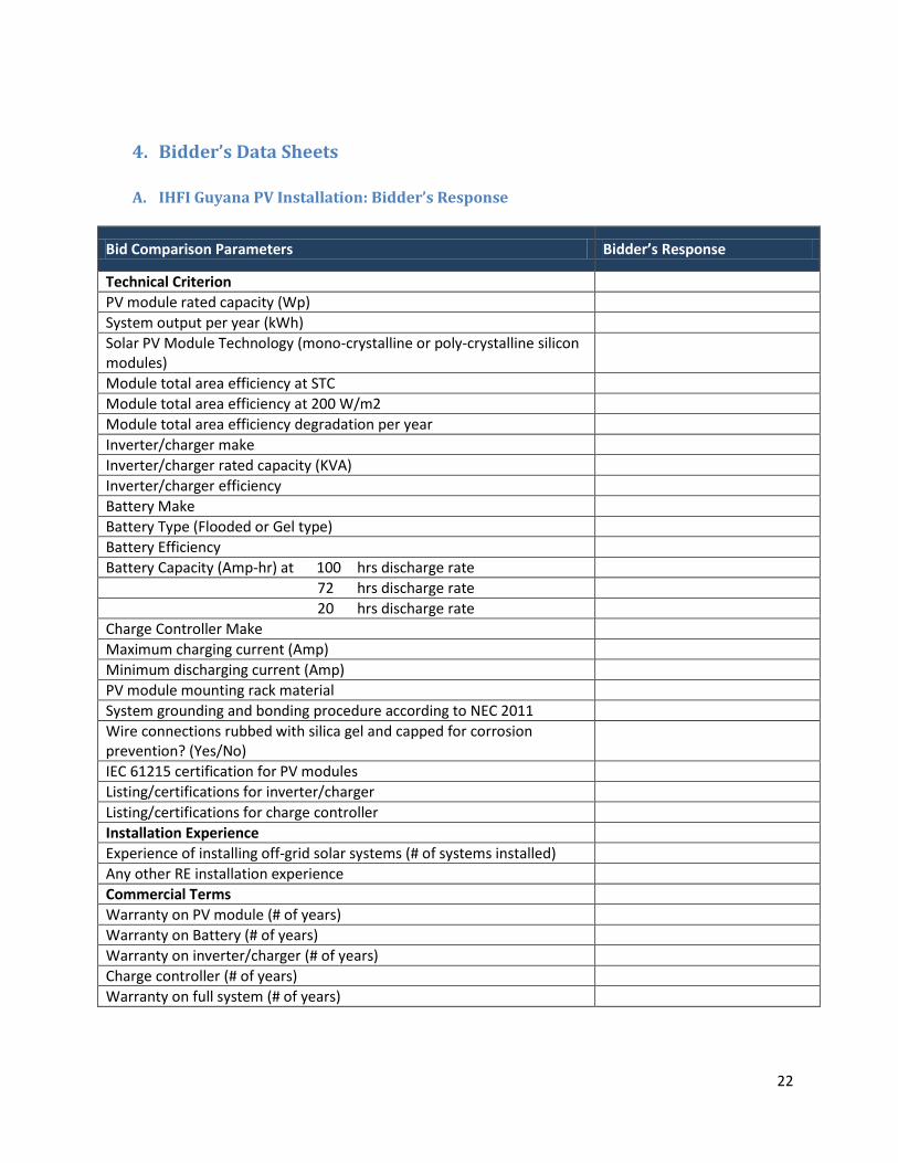
4. Bidder’s Data Sheets
A. IHFI Guyana PV Installation: Bidder’s Response
Bid Comparison Parameters Bidder’s Response
Technical Criterion
PV module rated capacity (Wp)
System output per year (kWh)
Solar PV Module Technology (mono-crystalline or poly-crystalline silicon modules)
Module total area efficiency at STC
Module total area efficiency at 200 W/m2
Module total area efficiency degradation per year
Inverter/charger make
Inverter/charger rated capacity (KVA)
Inverter/charger efficiency
Battery Make
Battery Type (Flooded or Gel type)
Battery Efficiency
Battery Capacity (Amp-hr) at 100 hrs discharge rate
72 hrs discharge rate
20 hrs discharge rate
Charge Controller Make
Maximum charging current (Amp)
Minimum discharging current (Amp)
PV module mounting rack material
System grounding and bonding procedure according to NEC 2011
Wire connections rubbed with silica gel and capped for corrosion prevention? (Yes/No)
IEC 61215 certification for PV modules
Listing/certifications for inverter/charger
Listing/certifications for charge controller
Installation Experience
Experience of installing off-grid solar systems (# of systems installed)
Any other RE installation experience
Commercial Terms
Warranty on PV module (# of years)
Warranty on Battery (# of years)
Warranty on inverter/charger (# of years)
Charge controller (# of years)
Warranty on full system (# of years)
23
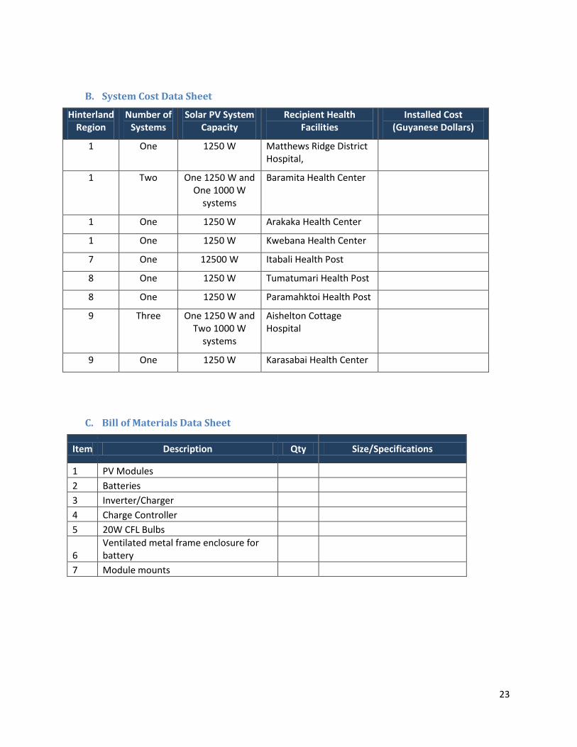
B. System Cost Data Sheet
Hinterland Region
Number of Systems
Solar PV System Capacity
Recipient Health Facilities
Installed Cost (Guyanese Dollars)
1 One 1250 W Matthews Ridge District Hospital,
1 Two One 1250 W and One 1000 W
systems
Baramita Health Center
1 One 1250 W Arakaka Health Center
1 One 1250 W Kwebana Health Center
7 One 12500 W Itabali Health Post
8 One 1250 W Tumatumari Health Post
8 One 1250 W Paramahktoi Health Post
9 Three One 1250 W and Two 1000 W
systems
Aishelton Cottage Hospital
9 One 1250 W Karasabai Health Center
C. Bill of Materials Data Sheet
Item Description Qty Size/Specifications
1 PV Modules
2 Batteries
3 Inverter/Charger
4 Charge Controller
5 20W CFL Bulbs
6 Ventilated metal frame enclosure for battery
7 Module mounts

24
Appendix A; Site drawings- Proposed sighting of solar system MATTHEWS RIDGE DISTRICT HOSPITAL: Proposed site for placement of the PV panels
ARAKAKA HEALTH CENTER: Proposed site for placement of the PV panels

25
BARAMITA HEALTH CENTER: Proposed site for placement of the PV panels
Kwebana Health Center – Proposed site for PV system installation
Itabali Health Post - Proposed site for PV system installation

26
Paramakatoi - proposed site for the PV panels
Tumatumari Health Post
27
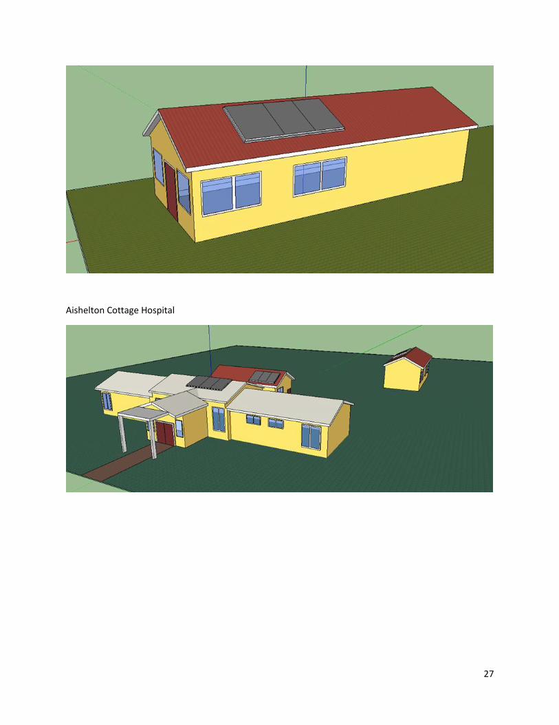
Aishelton Cottage Hospital

28
Appendix B: Health Facility Floor Plan – Solar Systems Wiring Diagram
MATTHEWS RIDGE
Arakaka Health Center

29
Baramita Health Center

30
Kwebana Health Center
Itabali Health Post

31
Paramakatoi Health Center
Tumatumari Health Post
Karasabai Health Center

32
Aishelton Cottage Hospital

33

34
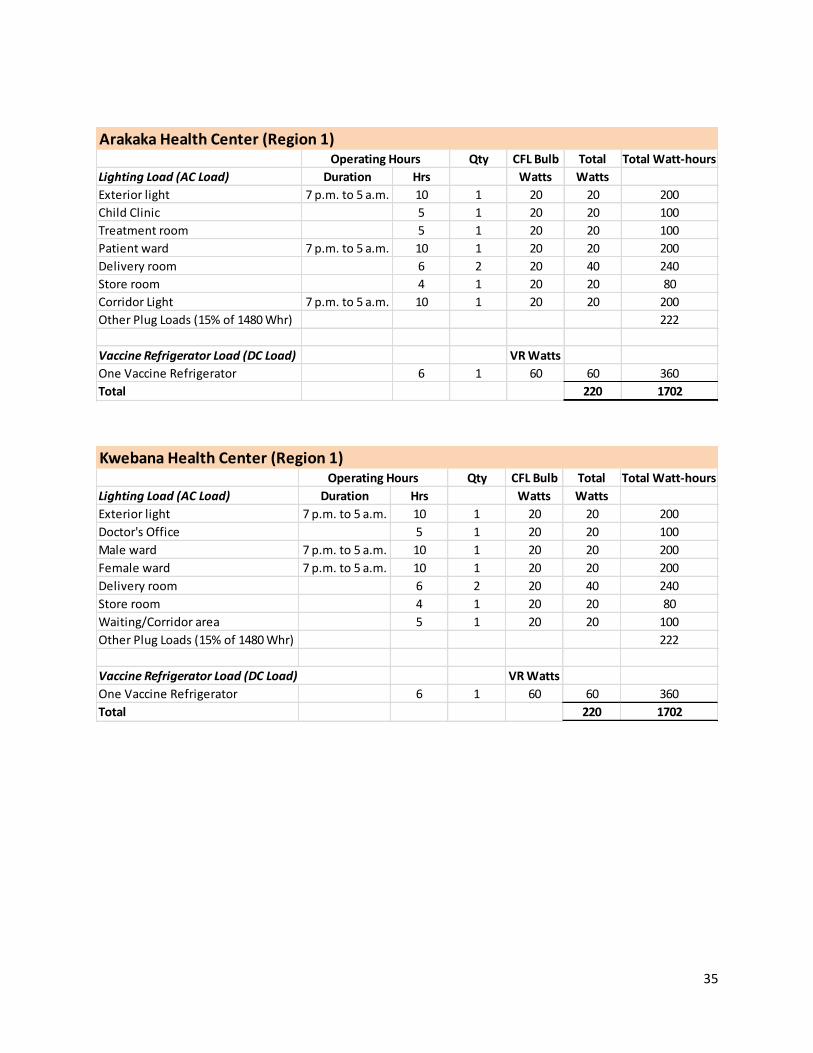
Appendix C: Load and energy requirement for health clinics
Mathews Ridge District Hospital (Region 1)Qty CFL Bulb Total Total Watt-hours
Lighting Load (AC Load) Duration Hrs Watts Watts
Male Ward 7 p.m. to 5 a.m. 10 1 20 20 200
Nurse's Station 7 p.m. to 5 a.m. 10 1 20 20 200
Pharmacy 4 1 20 20 80
Female Ward 7 p.m. to 5 a.m. 10 1 20 20 200
Treatment Room 4 1 20 20 80
Delivery Room 6 1 20 20 120
Labor Room 6 1 20 20 120
Maternity Clinic 6 1 20 20 120
Other Plug Loads (15% of 1480 Whr) 222
Vaccine Refrigerator Load (DC Load) VR Watts
Vaccine Refrigerator (VR) 6 1 60 60 360
Total 220 1702
Operating Hours
Baramita Health Center (Region 1)Front Building Qty CFL Bulb Total Total Watt-hours
Lighting Load (AC Load) Duration Hrs Watts Watts
Exterior light 7 p.m. to 5 a.m. 10 1 20 20 200
Staff quarter 6 1 20 20 120
Outpatient Room 5 1 20 20 100
Patient ward/Malarial room 7 p.m. to 5 a.m. 10 1 20 20 200
Delivery room 6 1 20 20 120
Store room/Vacc. Ref room 4 1 20 20 80
Medicine Storage 5 1 20 20 100
Corridor Light 7 p.m. to 5 a.m. 10 1 20 20 200
Other Plug Loads (15% of 1480 Whr) 222
Vaccine Refrigerator Load (DC Load) VR Watts
One Vaccine Refrigerator 6 1 60 60 360
Total 220 1702
Rear Building Qty CFL Bulb Total Total Watt-hours
AC Load Duration Hrs Watts Watts
Exterior light 7 p.m. to 5 a.m. 10 1 20 20 200
Patient ward 7 p.m. to 5 a.m. 10 1 20 20 200
Malaria Lab 5 1 20 20 100
Other indoor areas 6 5 20 100 600
Other Plug Loads (15% of 1100 Whr) 165
Total 160 1265
Operating Hours
Operating Hours
35
Arakaka Health Center (Region 1)Qty CFL Bulb Total Total Watt-hours
Lighting Load (AC Load) Duration Hrs Watts Watts
Exterior light 7 p.m. to 5 a.m. 10 1 20 20 200
Child Clinic 5 1 20 20 100
Treatment room 5 1 20 20 100
Patient ward 7 p.m. to 5 a.m. 10 1 20 20 200
Delivery room 6 2 20 40 240
Store room 4 1 20 20 80
Corridor Light 7 p.m. to 5 a.m. 10 1 20 20 200
Other Plug Loads (15% of 1480 Whr) 222
Vaccine Refrigerator Load (DC Load) VR Watts
One Vaccine Refrigerator 6 1 60 60 360
Total 220 1702
Operating Hours
Kwebana Health Center (Region 1)Qty CFL Bulb Total Total Watt-hours
Lighting Load (AC Load) Duration Hrs Watts Watts
Exterior light 7 p.m. to 5 a.m. 10 1 20 20 200
Doctor's Office 5 1 20 20 100
Male ward 7 p.m. to 5 a.m. 10 1 20 20 200
Female ward 7 p.m. to 5 a.m. 10 1 20 20 200
Delivery room 6 2 20 40 240
Store room 4 1 20 20 80
Waiting/Corridor area 5 1 20 20 100
Other Plug Loads (15% of 1480 Whr) 222
Vaccine Refrigerator Load (DC Load) VR Watts
One Vaccine Refrigerator 6 1 60 60 360
Total 220 1702
Operating Hours

36
Itabali Health Center (Region 7)Qty CFL Bulb Total Total Watt-hours
Lighting Load (AC Load) Duration Hrs Watts Watts
Exterior light 7 p.m. to 5 a.m. 10 2 20 40 400
Nurse/CWH Station 5 1 20 20 100
Outpatient area 5 1 20 20 100
Examination room 6 1 20 20 120
Washroom 4 1 20 20 80
Maternal & Child Health 6 1 20 20 120
Corridor Light 7 p.m. to 5 a.m. 10 1 20 20 200
Other Plug Loads (15% of 1480 Whr) 222
Vaccine Refrigerator Load (DC Load) VR Watts
One Vaccine Refrigerator 6 1 60 60 360
Total 220 1702
Operating Hours
Tumatumari Health Post (Region 8)Qty CFL Bulb Total Total Watt-hours
Lighting Load (AC Load) Duration Hrs Watts Watts
Exterior light 7 p.m. to 5 a.m. 10 1 20 20 200
Maternity room 7 p.m. to 5 a.m. 10 1 20 20 200
Store/pharmacy 6 1 20 20 120
CHW Room 6 1 20 20 120
Nurse's room 7 p.m. to 5 a.m. 10 1 20 20 200
Washroom 5 1 20 20 100
Outpatient area 4 1 20 20 80
Corridor light 5 1 20 20 100
Other Plug Loads (15% of 1480 Whr) 222
Vaccine Refrigerator Load (DC Load) VR Watts
One Vaccine Refrigerator 6 1 60 60 360
Total 220 1702
Operating Hours

37
Paramahaktoi Health Center (Region 8)Qty CFL Bulb Watts Total Watt-hours
Lighting Load (AC Load) Duration Hrs Watts
Exterior light 7 p.m. to 5 a.m. 10 1 20 20 200
Female ward 7 p.m. to 5 a.m. 10 1 20 20 200
Outpatient Room 5 1 20 20 100
Delivery room 6 2 20 40 240
Male ward 7 p.m. to 5 a.m. 10 1 20 20 200
Radio/Vacc. Ref. room 5 1 20 20 100
Washroom 4 1 20 20 80
Other Plug Loads (15% of 1480 Whr) 222
Vaccine Refrigerator Load (DC Load) VR Watts
One Vaccine Refrigerator 6 1 60 60 360
Total 220 1702
Operating Hours
Karasabai Health Center (Region 9)Qty CFL Bulb Total Total Watt-hours
Lighting Load (AC Load) Duration Hrs Watts Watts
Exterior light 7 p.m. to 5 a.m. 10 1 20 20 200
Corridor light 4 2 20 40 160
Male ward 7 p.m. to 5 a.m. 10 1 20 20 200
Maternity ward 7 p.m. to 5 a.m. 10 2 20 40 400
Outpatient area 4 1 20 20 80
Nurse's Office 4 1 20 20 80
Other Plug Loads (15% of 1480 Whr) 222
Vaccine Refrigerator Load (DC Load) VR Watts
One Vaccine Refrigerator 6 1 60 60 360
Total 220 1702
Operating Hours

38
Aishelton Cottage Hospital (Region 9)Qty CFL Bulb Total Total Watt-hours
Lighting Load (AC Load) Duration Hrs Watts Watts
Exterior light 7 p.m. to 5 a.m. 10 1 20 20 200
Outpatient area 6 1 20 20 120
Male ward 7 p.m. to 5 a.m. 10 1 20 20 200
Female ward 7 p.m. to 5 a.m. 10 1 20 20 200
Treatment Room 5 1 20 20 100
AHO Office 5 1 20 20 100
Corridor lights 5 2 20 40 200
Other Plug Loads (15% of 1480 Whr) 222
Vaccine Refrigerator Load (DC Load) VR Watts
One Vaccine Refrigerator 6 1 60 60 360
Total 200 220 1702
Female and Pediatric Ward Qty CFL Bulb Total Total Watt-hours
Duration Hrs Watts Watts
Immunization room 3 1 20 20 60
Nurse's Station 7 p.m. to 5 a.m. 10 1 20 20 200
Pediatric ward 7 p.m. to 5 a.m. 10 1 20 20 200
Male ward 7 p.m. to 5 a.m. 10 1 20 20 200
Female Ward 7 p.m. to 5 a.m. 10 2 20 40 400
Washrooms and store 1 2 20 40 40
Other Plug Loads (15% of 1100 Whr) 165
Total 160 1265
Rear Building Qty CFL Bulb Total Total Watt-hours
Duration Hrs Watts Watts
Exterior light 7 p.m. to 5 a.m. 10 1 20 20 200
Labor room 7 p.m. to 5 a.m. 10 2 20 40 400
Maternity Ward 10 2 20 40 400
Infant warmer room 3 1 20 20 60
Storage room 2 1 20 20 40
Other Plug Loads (15% of 1100 Whr) 165
Total 140 1265
Operating Hours
Operating Hours
Operating Hours