Embed Size (px)
Citation preview
General Description
Features
Process/Temperature Controller FB100/400/900
FB100FB400FB900
The FB Series is a high performance process controller with a more advanced Brilliant II PID, autotuning, selectable sampling cycle time of 0.05/0.1/0.25 second and 0.1% of accuracy in short depth housing. Applications include various plastic machines (extrudes, injection machine, etc), electric furnaces, semiconductor, food processing, environmental chambers and many others.
High Accuracy with selectable sampling cycle timeThe depth of 60mm (FB100 : 74mm)Inter-cntroller CommunicationBrilliant II PID controlStart-up tuning and Autotuniung
The FB Series has very short depth as a 1/16, 1/8 or 1/4 DIN size controller. The series was designed with a mounting bracket that allows close horizontal mounting of as many as six units.
Panel space saving
Easy maintenanceThe internal assembly of the FB Series can be removed from
the front.
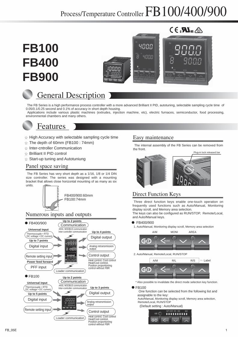
Three direct function keys enable one-touch operation on frequently used functions such as Auto/Manual, Monitoring display scroll, and Memory area selection. The keys can also be configured as RUN/STOP, Remote/Local, and Auto/Manual keys.
Direct Function Keys
Plug-in lock released bar
R/S
A/M
A/M R/L
MONI AREA
1. Auto/Manual, Monitoring display scroll, Memory area selection
2. Auto/Manual, Remote/Local, RUN/STOP
Label
* Also possible to invalidate the direct mode selection key function.
FB400/900:60mmFB100:74mm
FB400/900
FB100
Numerous inputs and outputs
Digital input
Universal input
Power feed forward
Remote setting input
PFF input
Thermocouple • RTDDC voltage • DC current
CommunicationANSI, MODBUS communication
Digital outputUp to 4 points
Digital outputUp to 3 points
Analog retransmissionoutput
Analog retransmissionoutput
Control outputHeat control, Cool controlHeat/Cool contriol,Position proportioningcontrol without FBR
Control outputHeat control, Cool controlHeat/Cool contriol,Position proportioningcontrol without FBR
Up to 2 points
Inter-controller communication
CommunicationANSI, MODBUS communication
Up to 2 points
Inter-controller communication
Up to 7 points
Digital input
Universal input
Remote setting input
Thermocouple • RTDDC voltage • DC current
Up to 5 points
Loader communication
Loader communication
FB400/900
FB100One function can be selected from the following list and
assignable to the key:
(Default setting : Auto/Manual)
Auto/Manual, Monitoring display scroll, Memory area selection,Remote/Local, RUN/STOP
1FB_05E
Features
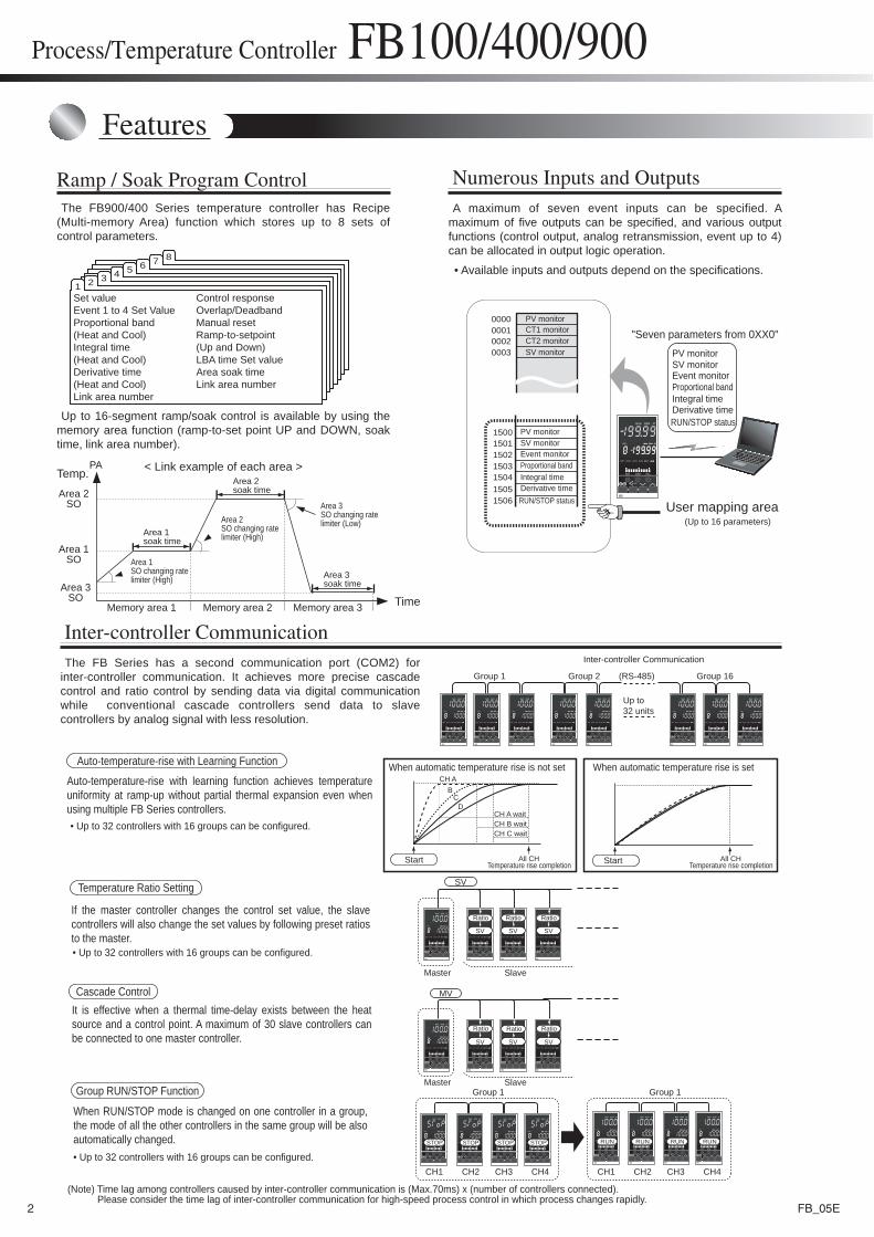
A maximum of seven event inputs can be specified. A maximum of five outputs can be specified, and various output functions (control output, analog retransmission, event up to 4) can be allocated in output logic operation.
Numerous Inputs and Outputs
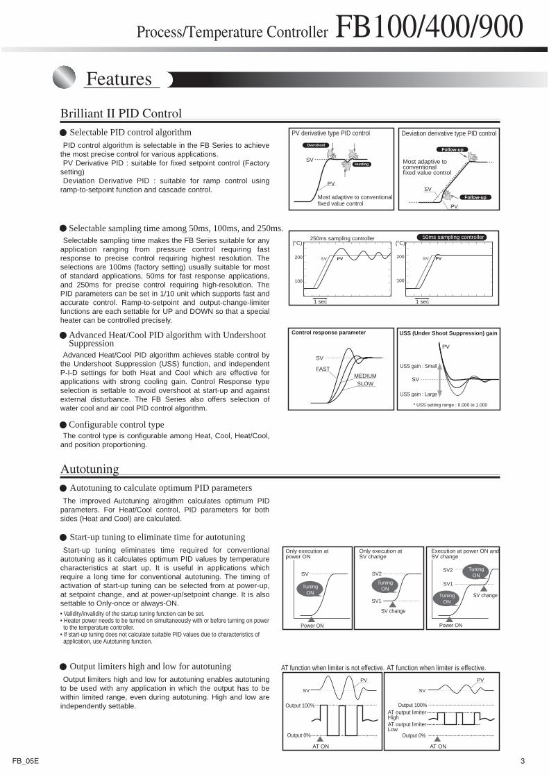
The FB Series has a second communication port (COM2) for inter-controller communication. It achieves more precise cascade control and ratio control by sending data via digital communication while conventional cascade controllers send data to slave controllers by analog signal with less resolution.
Inter-controller Communication
The FB900/400 Series temperature controller has Recipe (Multi-memory Area) function which stores up to 8 sets of control parameters.
Up to 16-segment ramp/soak control is available by using the memory area function (ramp-to-set point UP and DOWN, soak time, link area number).
Ramp / Soak Program Control
1 2 3 4 5 6 7 8
Set valueEvent 1 to 4 Set ValueProportional band(Heat and Cool)Integral time(Heat and Cool)Derivative time(Heat and Cool)Link area number
Control responseOverlap/DeadbandManual resetRamp-to-setpoint(Up and Down)LBA time Set valueArea soak timeLink area number
< Link example of each area >Temp.
Time
PA
Area 1soak time
Area 1SO changing ratelimiter (High)
Area 2SO changing ratelimiter (High)
Memory area 1 Memory area 2
Area 2SO
Area 1SO
Area 3SO
Memory area 3
Area 2soak time
Area 3soak time
Area 3SO changing ratelimiter (Low)
• Available inputs and outputs depend on the specifications.
Process/Temperature Controller FB100/400/900
0000000100020003
1500150115021503150415051506
PV monitor
SV monitor
PV monitorSV monitorEvent monitorProportional bandIntegral timeDerivative time
CT1 monitorCT2 monitor
RUN/STOP status
PV monitorSV monitorEvent monitorProportional bandIntegral timeDerivative timeRUN/STOP status
"Seven parameters from 0XX0"
User mapping area(Up to 16 parameters)
(RS-485)
Inter-controller Communication
Up to32 units
Group 1 Group 2 Group 16
When automatic temperature rise is not set When automatic temperature rise is setCH A
CH A wait
B
DC
All CH
CH B waitCH C wait
Auto-temperature-rise with learning function achieves temperature uniformity at ramp-up without partial thermal expansion even when using multiple FB Series controllers. • Up to 32 controllers with 16 groups can be configured.
Auto-temperature-rise with Learning Function
Master Slave
Master SlaveGroup 1 Group 1
CH1 CH3CH2 CH4 CH1 CH3CH2 CH4
SV
MV
Ratio Ratio
SV SV SV
SV SV SV
STOP STOP STOP STOP RUN RUN RUN RUN
It is effective when a thermal time-delay exists between the heat source and a control point. A maximum of 30 slave controllers can be connected to one master controller.
If the master controller changes the control set value, the slave controllers will also change the set values by following preset ratios to the master.
When RUN/STOP mode is changed on one controller in a group, the mode of all the other controllers in the same group will be also automatically changed.
• Up to 32 controllers with 16 groups can be configured.
Temperature Ratio Setting
Group RUN/STOP Function
Cascade Control
• Up to 32 controllers with 16 groups can be configured.
(Note) Time lag among controllers caused by inter-controller communication is (Max.70ms) x (number of controllers connected). Please consider the time lag of inter-controller communication for high-speed process control in which process changes rapidly.
Temperature rise completionAll CH
Temperature rise completionStart Start
Ratio
Ratio Ratio Ratio
2 FB_05E
Features
Process/Temperature Controller FB100/400/900
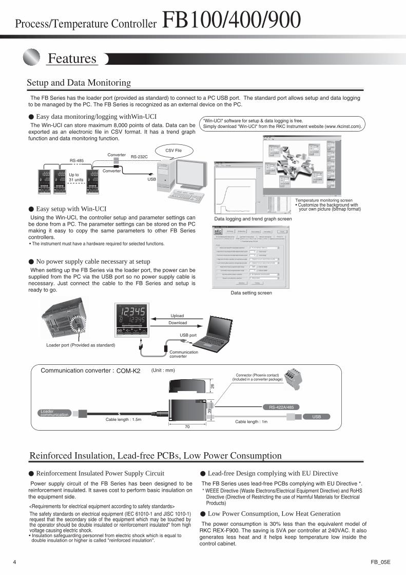
PID control algorithm is selectable in the FB Series to achieve the most precise control for various applications.PV Derivative PID : suitable for fixed setpoint control (Factory
setting)Deviation Derivative PID : suitable for ramp control using
ramp-to-setpoint function and cascade control.
Selectable sampling time makes the FB Series suitable for any application ranging from pressure control requiring fast response to precise control requiring highest resolution. The selections are 100ms (factory setting) usually suitable for most of standard applications, 50ms for fast response applications, and 250ms for precise control requiring high-resolution. The PID parameters can be set in 1/10 unit which supports fast and accurate control. Ramp-to-setpoint and output-change-limiter functions are each settable for UP and DOWN so that a special heater can be controlled precisely.
Advanced Heat/Cool PID algorithm achieves stable control by the Undershoot Suppression (USS) function, and independent P-I-D settings for both Heat and Cool which are effective for applications with strong cooling gain. Control Response type selection is settable to avoid overshoot at start-up and against external disturbance. The FB Series also offers selection of water cool and air cool PID control algorithm.
The control type is configurable among Heat, Cool, Heat/Cool, and position proportioning.
Brilliant II PID Control
SV
SVPV
PV
200 SV PV
100
200 SV PV
100
SV
SV
FASTMEDIUMSLOW
PV
SV SV
PV PV
PV derivative type PID control Deviation derivative type PID controlOvershoot
Hunting
Most adaptive to conventionalfixed value control
Follow-up
Follow-up
Most adaptive toconventionalfixed value control
250ms sampling controller 50ms sampling controller
1 sec 1 sec
(°C) (°C)
Control response parameter USS (Under Shoot Suppression) gain
USS gain : Small
USS gain : Large
* USS setting range : 0.000 to 1.000
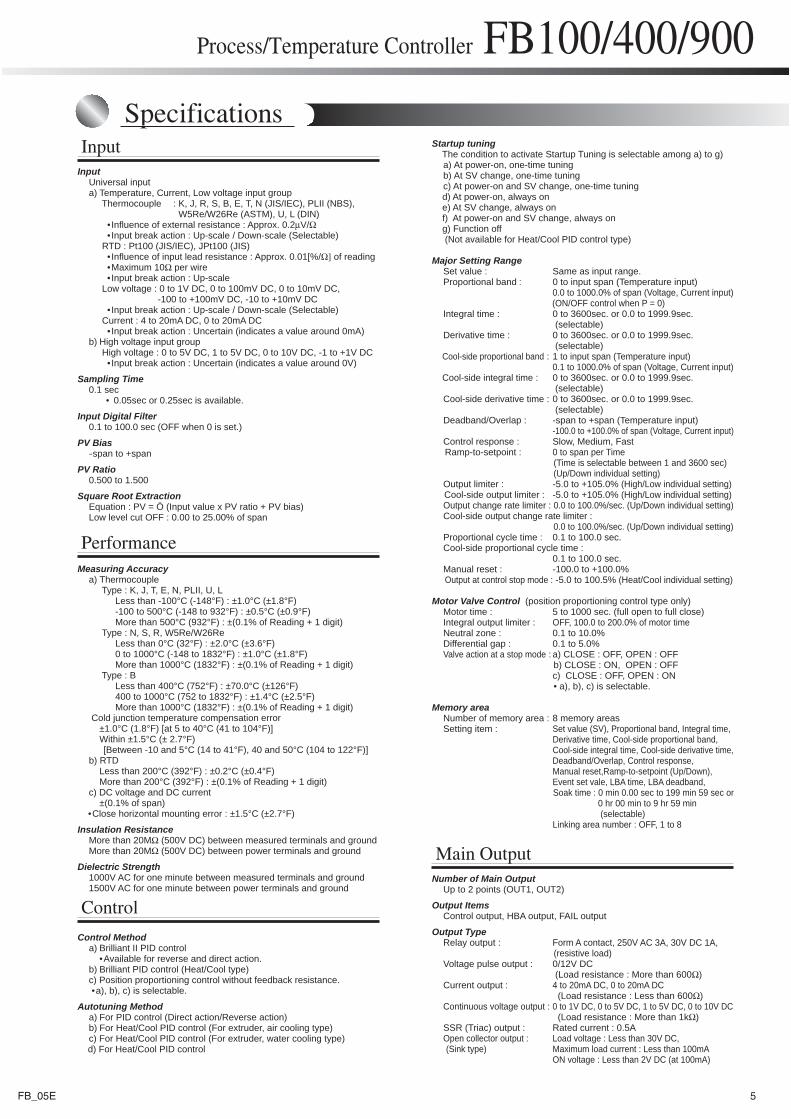
Only execution atpower ON
Only execution atSV change
Execution at power ON andSV change
AT function when limiter is effective.AT function when limiter is not effective.
TuningON
TuningON
TuningON
TuningON
SV
Power ON
SV2
SV1
SV2
SV1
SV change
Power ON
SV change
AT output limiterHighAT output limiterLow
Output 100%
Output 0%
Output 100%
Output 0%
AT ON AT ON
Selectable PID control algorithm
The improved Autotuning alrogithm calculates optimum PID parameters. For Heat/Cool control, PID parameters for both sides (Heat and Cool) are calculated.
AutotuningAutotuning to calculate optimum PID parameters
Output limiters high and low for autotuning enables autotuning to be used with any application in which the output has to be within limited range, even during autotuning. High and low are independently settable.
Output limiters high and low for autotuning
Start-up tuning eliminates time required for conventional autotuning as it calculates optimum PID values by temperature characteristics at start up. It is useful in applications which require a long time for conventional autotuning. The timing of activation of start-up tuning can be selected from at power-up, at setpoint change, and at power-up/setpoint change. It is also settable to Only-once or always-ON.
Start-up tuning to eliminate time for autotuning
Selectable sampling time among 50ms, 100ms, and 250ms.
Advanced Heat/Cool PID algorithm with UndershootSuppression
Configurable control type
• Validity/invalidity of the startup tuning function can be set. • Heater power needs to be turned on simultaneously with or before turning on power to the temperature controller.• If start-up tuning does not calculate suitable PID values due to characteristics of application, use Autotuning function.
3FB_05E
Features
Power supply circuit of the FB Series has been designed to be reinforcement insulated. It saves cost to perform basic insulation on the equipment side.
The FB Series uses lead-free PCBs complying with EU Directive *.
The Win-UCI can store maximum 8,000 points of data. Data can be exported as an electronic file in CSV format. It has a trend graph function and data monitoring function.
The FB Series has the loader port (provided as standard) to connect to a PC USB port. The standard port allows setup and data logging to be managed by the PC. The FB Series is recognized as an external device on the PC.
Setup and Data Monitoring
Process/Temperature Controller FB100/400/900
RS-485RS-232C
USB
A/M MONI AREA
FB900
PV
SV MV
70
26
RS-422A/485
USB
39
Easy data monitoring/logging withWin-UCI
Using the Win-UCI, the controller setup and parameter settings can be done from a PC. The parameter settings can be stored on the PC making it easy to copy the same parameters to other FB Series controllers.
Easy setup with Win-UCI
Up to31 units
CSV FileConverter
Converter
Data logging and trend graph screen
Temperature monitoring screen• Customize the background with your own picture (bitmap format)
"Win-UCI" software for setup & data logging is free.Simply download "Win-UCI" from the RKC Instrument website (www.rkcinst.com).
Data setting screen
• The instrument must have a hardware required for selected functions.
When setting up the FB Series via the loader port, the power can be supplied from the PC via the USB port so no power supply cable is necessary. Just connect the cable to the FB Series and setup is ready to go.
No power supply cable necessary at setup
Reinforcement Insulated Power Supply Circuit Lead-free Design complying with EU Directive
Loader port (Provided as standard)
USB port
Upload
Download
Communicationconverter
Communication converter : COM-K2
Cable length : 1m
(Unit : mm)Connector (Phoenix contact)
(Included in a converter package)
Cable length : 1.5m
Loader communication
Reinforced Insulation, Lead-free PCBs, Low Power Consumption
The safety standards on electrical equipment (IEC 61010-1 and JISC 1010-1) request that the secondary side of the equipment which may be touched by the operator should be double insulated or reinforcement insulated* from high voltage causing electric shock.
<Requirements for electrical equipment according to safety standards>
• Insulation safeguarding personnel from electric shock which is equal to double insulation or higher is called "reinforced insulation".
* WEEE Directive (Waste Electrons/Electrical Equipment Directive) and RoHS Directive (Directive of Restricting the use of Harmful Materials for Electrical Products)
The power consumption is 30% less than the equivalent model of RKC REX-F900. The saving is 5VA per controller at 240VAC. It also generates less heat and it helps keep temperature low inside the control cabinet.
Low Power Consumption, Low Heat Generation
4 FB_05E
Process/Temperature Controller FB100/400/900
SpecificationsInput
Main Output
Control
Input Universal input a) Temperature, Current, Low voltage input group Thermocouple : K, J, R, S, B, E, T, N (JIS/IEC), PLII (NBS), W5Re/W26Re (ASTM), U, L (DIN) • Influence of external resistance : Approx. 0.2μV/Ω • Input break action : Up-scale / Down-scale (Selectable) RTD : Pt100 (JIS/IEC), JPt100 (JIS) • Influence of input lead resistance : Approx. 0.01[%/Ω] of reading •Maximum 10Ω per wire • Input break action : Up-scale Low voltage : 0 to 1V DC, 0 to 100mV DC, 0 to 10mV DC, -100 to +100mV DC, -10 to +10mV DC • Input break action : Up-scale / Down-scale (Selectable) Current : 4 to 20mA DC, 0 to 20mA DC • Input break action : Uncertain (indicates a value around 0mA) b) High voltage input group High voltage : 0 to 5V DC, 1 to 5V DC, 0 to 10V DC, -1 to +1V DC • Input break action : Uncertain (indicates a value around 0V)
Sampling Time 0.1 sec • 0.05sec or 0.25sec is available.
Input Digital Filter 0.1 to 100.0 sec (OFF when 0 is set.)
PV Bias -span to +span
PV Ratio 0.500 to 1.500
Square Root Extraction Equation : PV = Ö (Input value x PV ratio + PV bias) Low level cut OFF : 0.00 to 25.00% of span
Control Method a) Brilliant II PID control •Available for reverse and direct action. b) Brilliant PID control (Heat/Cool type) c) Position proportioning control without feedback resistance. •a), b), c) is selectable.
Autotuning Method a) For PID control (Direct action/Reverse action) b) For Heat/Cool PID control (For extruder, air cooling type) c) For Heat/Cool PID control (For extruder, water cooling type) d) For Heat/Cool PID control
Startup tuning The condition to activate Startup Tuning is selectable among a) to g) a) At power-on, one-time tuning b) At SV change, one-time tuning c) At power-on and SV change, one-time tuning d) At power-on, always on e) At SV change, always on f) At power-on and SV change, always on g) Function off (Not available for Heat/Cool PID control type)
Major Setting Range Set value : Same as input range. Proportional band : 0 to input span (Temperature input) 0.0 to 1000.0% of span (Voltage, Current input) (ON/OFF control when P = 0) Integral time : 0 to 3600sec. or 0.0 to 1999.9sec. (selectable) Derivative time : 0 to 3600sec. or 0.0 to 1999.9sec. (selectable) Cool-side proportional band : 1 to input span (Temperature input) 0.1 to 1000.0% of span (Voltage, Current input) Cool-side integral time : 0 to 3600sec. or 0.0 to 1999.9sec. (selectable) Cool-side derivative time : 0 to 3600sec. or 0.0 to 1999.9sec. (selectable) Deadband/Overlap : -span to +span (Temperature input) -100.0 to +100.0% of span (Voltage, Current input) Control response : Slow, Medium, Fast Ramp-to-setpoint : 0 to span per Time (Time is selectable between 1 and 3600 sec) (Up/Down individual setting) Output limiter : -5.0 to +105.0% (High/Low individual setting) Cool-side output limiter : -5.0 to +105.0% (High/Low individual setting) Output change rate limiter : 0.0 to 100.0%/sec. (Up/Down individual setting) Cool-side output change rate limiter : 0.0 to 100.0%/sec. (Up/Down individual setting) Proportional cycle time : 0.1 to 100.0 sec. Cool-side proportional cycle time : 0.1 to 100.0 sec. Manual reset : -100.0 to +100.0% Output at control stop mode : -5.0 to 100.5% (Heat/Cool individual setting)
Motor Valve Control (position proportioning control type only) Motor time : 5 to 1000 sec. (full open to full close) Integral output limiter : OFF, 100.0 to 200.0% of motor time Neutral zone : 0.1 to 10.0% Differential gap : 0.1 to 5.0% Valve action at a stop mode : a) CLOSE : OFF, OPEN : OFF b) CLOSE : ON, OPEN : OFF c) CLOSE : OFF, OPEN : ON • a), b), c) is selectable.
Memory area Number of memory area : 8 memory areas Setting item : Set value (SV), Proportional band, Integral time, Derivative time, Cool-side proportional band, Cool-side integral time, Cool-side derivative time, Deadband/Overlap, Control response, Manual reset,Ramp-to-setpoint (Up/Down), Event set vale, LBA time, LBA deadband, Soak time : 0 min 0.00 sec to 199 min 59 sec or 0 hr 00 min to 9 hr 59 min (selectable) Linking area number : OFF, 1 to 8
Number of Main Output Up to 2 points (OUT1, OUT2)
Output Items Control output, HBA output, FAIL output
Output Type Relay output : Form A contact, 250V AC 3A, 30V DC 1A, (resistive load) Voltage pulse output : 0/12V DC (Load resistance : More than 600Ω) Current output : 4 to 20mA DC, 0 to 20mA DC (Load resistance : Less than 600Ω) Continuous voltage output : 0 to 1V DC, 0 to 5V DC, 1 to 5V DC, 0 to 10V DC (Load resistance : More than 1kΩ) SSR (Triac) output : Rated current : 0.5A Open collector output : Load voltage : Less than 30V DC, (Sink type) Maximum load current : Less than 100mA ON voltage : Less than 2V DC (at 100mA)
PerformanceMeasuring Accuracy a) Thermocouple Type : K, J, T, E, N, PLII, U, L Less than -100°C (-148°F) : ±1.0°C (±1.8°F) -100 to 500°C (-148 to 932°F) : ±0.5°C (±0.9°F) More than 500°C (932°F) : ±(0.1% of Reading + 1 digit) Type : N, S, R, W5Re/W26Re Less than 0°C (32°F) : ±2.0°C (±3.6°F) 0 to 1000°C (-148 to 1832°F) : ±1.0°C (±1.8°F) More than 1000°C (1832°F) : ±(0.1% of Reading + 1 digit) Type : B Less than 400°C (752°F) : ±70.0°C (±126°F) 400 to 1000°C (752 to 1832°F) : ±1.4°C (±2.5°F) More than 1000°C (1832°F) : ±(0.1% of Reading + 1 digit) Cold junction temperature compensation error ±1.0°C (1.8°F) [at 5 to 40°C (41 to 104°F)] Within ±1.5°C (± 2.7°F) [Between -10 and 5°C (14 to 41°F), 40 and 50°C (104 to 122°F)] b) RTD Less than 200°C (392°F) : ±0.2°C (±0.4°F) More than 200°C (392°F) : ±(0.1% of Reading + 1 digit) c) DC voltage and DC current ±(0.1% of span) •Close horizontal mounting error : ±1.5°C (±2.7°F)
Insulation Resistance More than 20MΩ (500V DC) between measured terminals and ground More than 20MΩ (500V DC) between power terminals and ground
Dielectric Strength 1000V AC for one minute between measured terminals and ground 1500V AC for one minute between power terminals and ground
5FB_05E
Specifications
Process/Temperature Controller FB100/400/900
Digital Input
Power feed forward input
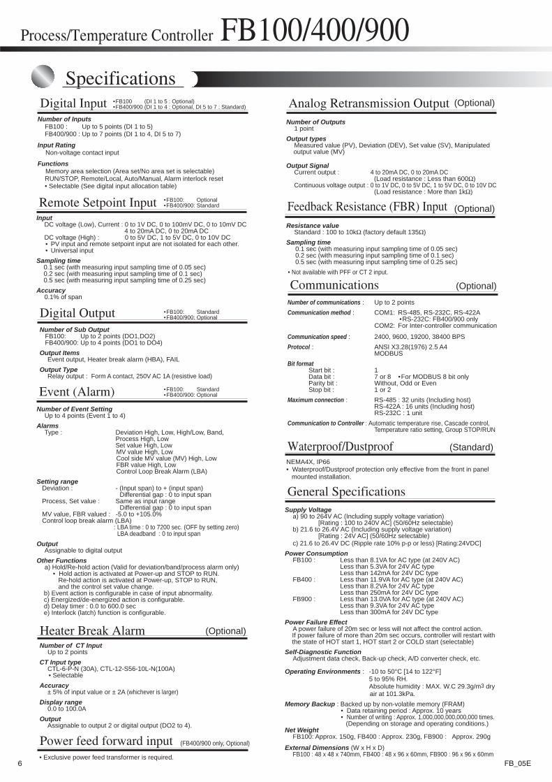
Number of Inputs FB100 : Up to 5 points (DI 1 to 5) FB400/900 : Up to 7 points (DI 1 to 4, DI 5 to 7)
Input Rating Non-voltage contact input
Functions Memory area selection (Area set/No area set is selectable) RUN/STOP, Remote/Local, Auto/Manual, Alarm interlock reset • Selectable (See digital input allocation table)
• Exclusive power feed transformer is required.
General SpecificationsSupply Voltage a) 90 to 264V AC (Including supply voltage variation) [Rating : 100 to 240V AC] (50/60Hz selectable) b) 21.6 to 26.4V AC (Including supply voltage variation) [Rating : 24V AC] (50/60Hz selectable) c) 21.6 to 26.4V DC (Ripple rate 10% p-p or less) [Rating:24VDC] Power Consumption FB100 : Less than 8.1VA for AC type (at 240V AC) Less than 5.3VA for 24V AC type Less than 142mA for 24V DC type FB400 : Less than 11.9VA for AC type (at 240V AC) Less than 8.2VA for 24V AC type Less than 250mA for 24V DC type FB900 : Less than 13.0VA for AC type (at 240V AC) Less than 9.3VA for 24V AC type Less than 300mA for 24V DC typePower Failure Effect A power failure of 20m sec or less will not affect the control action. If power failure of more than 20m sec occurs, controller will restart with the state of HOT start 1, HOT start 2 or COLD start (selectable)Self-Diagnostic Function Adjustment data check, Back-up check, A/D converter check, etc.
Operating Environments : -10 to 50°C [14 to 122°F] 5 to 95% RH. Absolute humidity : MAX. W.C 29.3g/m3 dry air at 101.3kPa.Memory Backup : Backed up by non-volatile memory (FRAM) • Data retaining period : Approx. 10 years • Number of writing : Approx. 1,000,000,000,000,000 times. (Depending on storage and operating conditions.)Net Weight FB100: Approx. 150g, FB400 : Approx. 230g, FB900 : Approx. 290g
External Dimensions (W x H x D) FB100 : 48 x 48 x 740mm, FB400 : 48 x 96 x 60mm, FB900 : 96 x 96 x 60mm
Communications (Optional)
Number of communications : Up to 2 pointsCommunication method : COM1: RS-485, RS-232C, RS-422A •RS-232C: FB400/900 only COM2: For Inter-controller communication
Communication speed : 2400, 9600, 19200, 38400 BPSProtocol : ANSI X3.28(1976) 2.5 A4 MODBUSBit format Start bit : 1 Data bit : 7 or 8 •For MODBUS 8 bit only Parity bit : Without, Odd or Even Stop bit : 1 or 2Maximum connection : RS-485 : 32 units (Including host) RS-422A : 16 units (Including host) RS-232C : 1 unitCommunication to Controller : Automatic temperature rise, Cascade control, Temperature ratio setting, Group STOP/RUN
Feedback Resistance (FBR) Input
Event (Alarm)Number of Event Setting Up to 4 points (Event 1 to 4)Alarms Type : Deviation High, Low, High/Low, Band, Process High, Low Set value High, Low MV value High, Low Cool side MV value (MV) High, Low FBR value High, Low Control Loop Break Alarm (LBA) Setting range Deviation : - (Input span) to + (input span) Differential gap : 0 to input span Process, Set value : Same as input range Differential gap : 0 to input span MV value, FBR valued : -5.0 to +105.0% Control loop break alarm (LBA) : LBA time : 0 to 7200 sec. (OFF by setting zero) LBA deadband : 0 to input spanOutput Assignable to digital outputOther Functions a) Hold/Re-hold action (Valid for deviation/band/process alarm only) • Hold action is activated at Power-up and STOP to RUN. Re-hold action is activated at Power-up, STOP to RUN, and the control set value change. b) Event action is configurable in case of input abnormality. c) Energized/de-energized action is configurable. d) Delay timer : 0.0 to 600.0 sec e) Interlock (latch) function is configurable.
Digital OutputNumber of Sub Output FB100: Up to 2 points (DO1,DO2) FB400/900: Up to 4 points (DO1 to DO4)Output Items Event output, Heater break alarm (HBA), FAIL Output Type Relay output : Form A contact, 250V AC 1A (resistive load)
(Optional)
Heater Break AlarmNumber of CT Input Up to 2 pointsCT Input type CTL-6-P-N (30A), CTL-12-S56-10L-N(100A) • SelectableAccuracy ± 5% of input value or ± 2A (whichever is larger)Display range 0.0 to 100.0AOutput Assignable to output 2 or digital output (DO2 to 4).
(Optional)
(FB400/900 only, Optional)
Analog Retransmission OutputNumber of Outputs 1 pointOutput types Measured value (PV), Deviation (DEV), Set value (SV), Manipulated output value (MV)
Output Signal Current output : 4 to 20mA DC, 0 to 20mA DC (Load resistance : Less than 600Ω) Continuous voltage output : 0 to 1V DC, 0 to 5V DC, 1 to 5V DC, 0 to 10V DC (Load resistance : More than 1kΩ)
Resistance value Standard : 100 to 10kΩ (factory default 135Ω)Sampling time 0.1 sec (with measuring input sampling time of 0.05 sec) 0.2 sec (with measuring input sampling time of 0.1 sec) 0.5 sec (with measuring input sampling time of 0.25 sec) • Not available with PFF or CT 2 input.
(Optional)
Remote Setpoint InputInput DC voltage (Low), Current : 0 to 1V DC, 0 to 100mV DC, 0 to 10mV DC 4 to 20mA DC, 0 to 20mA DC DC voltage (High) : 0 to 5V DC, 1 to 5V DC, 0 to 10V DC • PV input and remote setpoint input are not isolated for each other. • Universal inputSampling time 0.1 sec (with measuring input sampling time of 0.05 sec) 0.2 sec (with measuring input sampling time of 0.1 sec) 0.5 sec (with measuring input sampling time of 0.25 sec)Accuracy 0.1% of span
Waterproof/Dustproof (Standard)NEMA4X, IP66 • Waterproof/Dustproof protection only effective from the front in panel mounted installation.
•FB100 (DI 1 to 5 : Optional)•FB400/900 (DI 1 to 4 : Optional, DI 5 to 7 : Standard)
•FB100: Optional•FB400/900: Standard
•FB100: Standard•FB400/900: Optional
•FB100: Standard•FB400/900: Optional
6 FB_05E
NA
Power supply
Output 1
Output 2
N12
34
Relay contact output
No supplied
Voltage pulse output : 0/12V DC
Triac (SSR) outputOpen collector output
DC mA, V (See Output Signal Code Table, Code : 4 to 8)
Relay contact outputVoltage pulse output : 0/12V DC
Triac (SSR) outputOpen collector output
DC mA, V (See Output Signal Code Table, Code : 3 to 8)
24V AC/DC100 to 240V AC
White caseBlack case
FDGAWZ
Case color
Initial setting
Instrument version
(OUT1)
(OUT2)
MV
TD
NMV
TD
Specifications
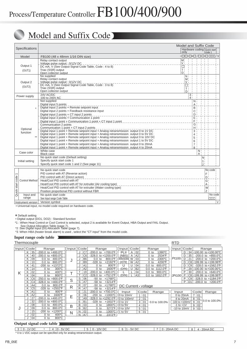
Model
Model and Suffix Code
FB100 (48 x 48mm 1/16 DIN size)
Y
6 1 - 5V DC 7 0 - 20mA DC3 0 - 1V DC 8 4 - 20mA DC5 0 - 10V DC4 0 - 5V DC
Output signal code table
Input range code table
No quick start code (Default setting)
Version symbol
Specify quick start code 1 and 2 (See page 11)Specify quick start code 1
No quick start code PID control with AT (Reverse action)
No quick start code
PID control with AT (Direct action)Heat/Cool PID control with ATHeat/Cool PID control with AT for extruder (Air cooling type)Heat/Cool PID control with AT for extruder (Water cooling type)Position proportional PID control without FBR
Control Method
Input andrange
Qui
ck s
tart
code
1
See Input range Code Table
Y
No code
Hardware codingonly
Quick startcode 1
No code
• Universal input, no model code required on hardware code.
tototototo
tototototototototototototototo
-200.0 +400.0°C-200.0 +800.0°C
0.0 400.0°C0.0 800.0°C
-200 +1372°C
0 400°C0 800°C
-250.0 +800.0°F-328.0 +400.0°F
0.0 800.0°F-328 +2502°F
0 800°F0 1600°F
-200.0 +400.0°C-200.0 +800.0°C
0.0 400.0°C0.0 800.0°C
-200 +1200°C0 400°C0 800°C
RangeCodeInputK 35K 40K 09K 10K 41
02Kto0 300°C14K
K 04K C6K C4K A4K C5K A1K A2J 27J 32J 08J 09J 15J 02J 04
K
J
totototototototototototototototototototo
-200.0 +700.0°F-328.0 +1200.0°F
0.0 800.0°F-328 +2192°F
0 800°F0 1600°F
-200.0 +400.0°C-328.0 +752.0°F
-50 +1768°C-58 +3214°F-50 +1768°C-58 +3214°F
-200.0 +700.0°C-200 +1000°C
-328.0 +1292.0°F-328 +1832°F
0 1800°C0 3272°F0 1300°C0 2372°F
RangeCodeInputJ C7J C6J B6J B9
A1JJ A2T 19T C2S 06S A7R 07R A7E 21E 06E A9E B1B 03B B2N 02N A7
J
T
SR
E
BN
Thermocouple
totototototototo
0 1390°C0 2534°F0 2300°C0 4200°F
0.0 600.0°C0.0 1112.0°F0.0 900.0°C0.0 1652.0°F
RangeCodeInputA 02A A2W 03W A2U 04
B2UL 04L A3
totototototototototo
-100.00 +100.00°C-200.0 +850.0°C-200.0 +200.0°C
-199.99 +199.99°F-328.0 +1562.0°F
-100.00 +100.00°C-200.0 +640.0°C
-199.99 +199.99°F-328.0 +1184.0°F-200.0 +200.0°F
RangeCodeInputD 34D 35D 21D C8D C9
29PP 30P C8P C9P D1
Pt100
JPt100
W5Re/W26Re(NBS)PLII
(DIN)U
(DIN)L
(ASTM)
RTD
RangeCodeInput1 012 013 014 015 01
016
DC Current • Voltage
0 to 10mV0 to 100mV0 to 1V0 to 5V0 to 10V1 to 5V
RangeCodeInput7 018 019 019 029 03
0 to 20mA4 to 20mA
-100 to +100mV-1 to +1V
-10 to 10mV
0.0 to 100.0%0.0 to 100.0%
* 0 to 1 VDC output can be specified only for analog retransmission output.*
*
**
Process/Temperature Controller FB100/400/900
Model and Suffix Code
NABCDEFGH345678
*2 :See Digital Input (DI) Allocation Table (page 7).
Default setting • Digital output (DO1, DO2) : Standard function
Optionalfunction
Not suppliedDigital input 5 pointsDigital input 2 points + Remote setpoint inputDigital input 2 points + Feedback resistance inputDigital input 2 points + CT input 2 pointsDigital input 3 points + Communication 1 pointDigital input 1 point + Communication 1 point + CT input 1 point
Digital input 1 point + Remote setpoint input + Analog retransmission output 0 to 1V DCDigital input 1 point + Remote setpoint input + Analog retransmission output 0 to 5V DCDigital input 1 point + Remote setpoint input + Analog retransmission output 0 to 10V DCDigital input 1 point + Remote setpoint input + Analog retransmission output 1 to 5V DCDigital input 1 point + Remote setpoint input + Analog retransmission output 0 to 20mADigital input 1 point + Remote setpoint input + Analog retransmission output 4 to 20mA
Communication 1 point + CT input 2 pointsCommunication 2 points
*1 : When Heat Control or Cool Control is selected, output 2 is available for Event Output, HBA Output and FAIL Output. See Output Allocation Table (page 7).
*3 :When HBA (heater break alarm) is used , select the "CT input" from the model code.
7FB_05E
Process/Temperature Controller FB100/400/900
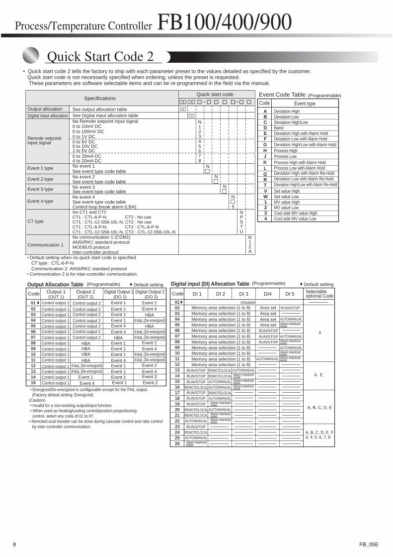
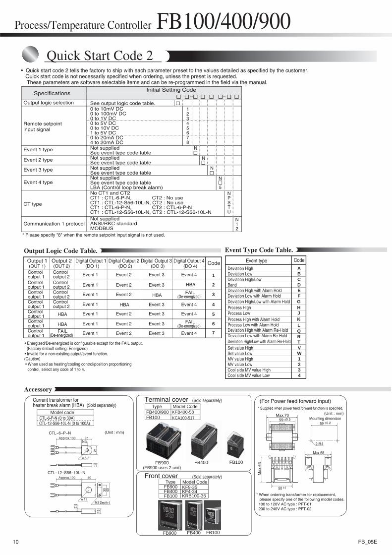
• Quick start code 2 tells the factory to ship with each parameter preset to the values detailed as specified by the customer. Quick start code is not necessarily specified when ordering, unless the preset is requested. These parameters are software selectable items and can be re-programmed in the field via the manual.
Quick Start Code 2
N12345678
N
5NPSTU
N12A
Quick start code
Output allocationDigital input allocation
Event 1 type
Event 2 type
Event 3 type
Event 4 type
CT type
0 to 1V DC
0 to 10V DC1 to 5V DC0 to 20mA DC4 to 20mA DCNo event 1
No event 2
Control loop break alarm (LBA)
CT1 : CTL-6-P-N, CT2 : No useCT1 : CTL-12-S56-10L-N, CT2 : No useCT1 : CTL-6-P-N, CT2 : CTL-6-P-NCT1 : CTL-12-S56-10L-N, CT2 : CTL-12-S56-10L-NNo communication 1 (COM1)ANSI/RKC standard protocolMODBUS protocolInter-controller protocol
Communication 1
0 to 5V DC
See output allocation tableSee Digital input allocation table
See event type code table
See event type code tableNo event 3See event type code table
0 to 10mV DC0 to 100mV DC
No CT1 and CT2
No event 4See event type code table
Remote setpointinput signal
No Remote setpoint input signal
N
• Default setting when no quick start code is specified. CT type : CTL-6-P-N Communication 2 :ANSI/RKC standard protocol • Communication 2 is for inter-controller communication.
Specifications
N
N
Event Code Table (Programmable)Code Event type
Deviation HighDeviation LowDeviation High/LowBandDeviation High with Alarm HoldDeviation Low with Alarm Hold
Process High with Alarm HoldProcess Low with Alarm Hold
ABCDEF
Deviation High/Low with Alarm Hold
Deviation High with Alarm Re-HoldDeviation Low with Alarm Re-HoldDeviation High/Low with Alarm Re-Hold
Process HighProcess Low
GHJKLQRT
Set value HighSet value LowMV value HighMV value LowCool side MV value HighCool side MV value Low
VW1234
010203040506070809101112131415
Code Output 1(OUT 1)
Output 2(OUT 2)
Digital Output 1(DO 1)
Digital Output 2(DO 2)
Control output 1 Control output 1 Control output 1 Control output 1 Control output 1 Control output 1 Control output 1 Control output 1 Control output 1 Control output 1 Control output 1 Control output 1 Control output 1 Control output 1 Control output 1
Control output 2 Control output 2 Control output 2 Control output 2 Control output 2 Control output 2 Control output 2
HBAHBAHBAHBA
FAIL(De-energized)FAIL(De-energized)
Event 1Event 4
Event 1Event 1Event 1
Event 1Event 1Event 1
Event 1Event 1
Event 1Event 4Event 4
Event 4
Event 1Event 2
HBA
Event 4Event 2
Event 4Event 2
Event 4Event 2
Event 2Event 3
HBAFAIL(De-energized)
HBAFAIL(De-energized)FAIL(De-energized)
FAIL(De-energized)FAIL(De-energized)
Output Allocation Table
• Energized/De-energized is configurable except for the FAIL output. (Factory default setting: Energized)(Caution) • Invalid for a non-existing output/input function. • When used as heating/cooling control/position proportioning control, select any code of 01 to 07.• Remote/Local transfer can be done during cascade control and ratio control by inter-controller communication.
Default setting
0102030405060708091011121314151617181920212223242526
Digital input (DI) Allocation Table
DI 1 DI 2 DI 3 DI 5
Memory area selection (1 to 8) Area setMemory area selection (1 to 8) Area set
Unused
Memory area selection (1 to 8) Area setMemory area selection (1 to 8)
Memory area selection (1 to 8)Memory area selection (1 to 8)
Memory area selection (1 to 8)Memory area selection (1 to 8)Memory area selection (1 to 8)Memory area selection (1 to 8)Memory area selection (1 to 8)
Area set Alarm interlockreset
RUN/STOP
AUTO/MANUAL
AUTO/MANUAL
Selectableoptional CodeDI4
RUN/STOPRUN/STOPRUN/STOP
RUN/STOPRUN/STOPRUN/STOP
RUN/STOPRUN/STOPRUN/STOP
RUN/STOP
Alarm interlockreset
Alarm interlockresetAlarm interlockreset
Alarm interlockreset
Alarm interlockresetAlarm interlockreset
Alarm interlockreset
Alarm interlockresetAlarm interlockresetAlarm interlockreset
REMOTE/LOCALREMOTE/LOCAL
REMOTE/LOCALREMOTE/LOCAL
REMOTE/LOCALREMOTE/LOCAL
REMOTE/LOCAL
A
A, E
A, B, C, D, E
A, B, C, D, E, F3, 4, 5, 6, 7, 8
Code
AUTO/MANUAL
AUTO/MANUAL
AUTO/MANUAL
AUTO/MANUALAUTO/MANUAL
AUTO/MANUAL
AUTO/MANUAL
AUTO/MANUAL
AUTO/MANUAL
Default setting(Programmable) (Programmable)
8 FB_05E
Process/Temperature Controller FB100/400/900
Model and Suffix Code
NA
Digital input
Power supply
Output 1
Output 2
N12
34
Relay contact output
No supplied
No supplied
Voltage pulse output : 0/12V DC
Triac (SSR) outputOpen collector output
DC mA, mV, V (See Output Signal Code Table, Code : 4 to 8)
Relay contact outputVoltage pulse output : 0/12V DC
Triac (SSR) outputOpen collector output
DC mA, mV, V (See Output Signal Code Table, Code : 3 to 8)
24V AC/DC100 to 240V AC
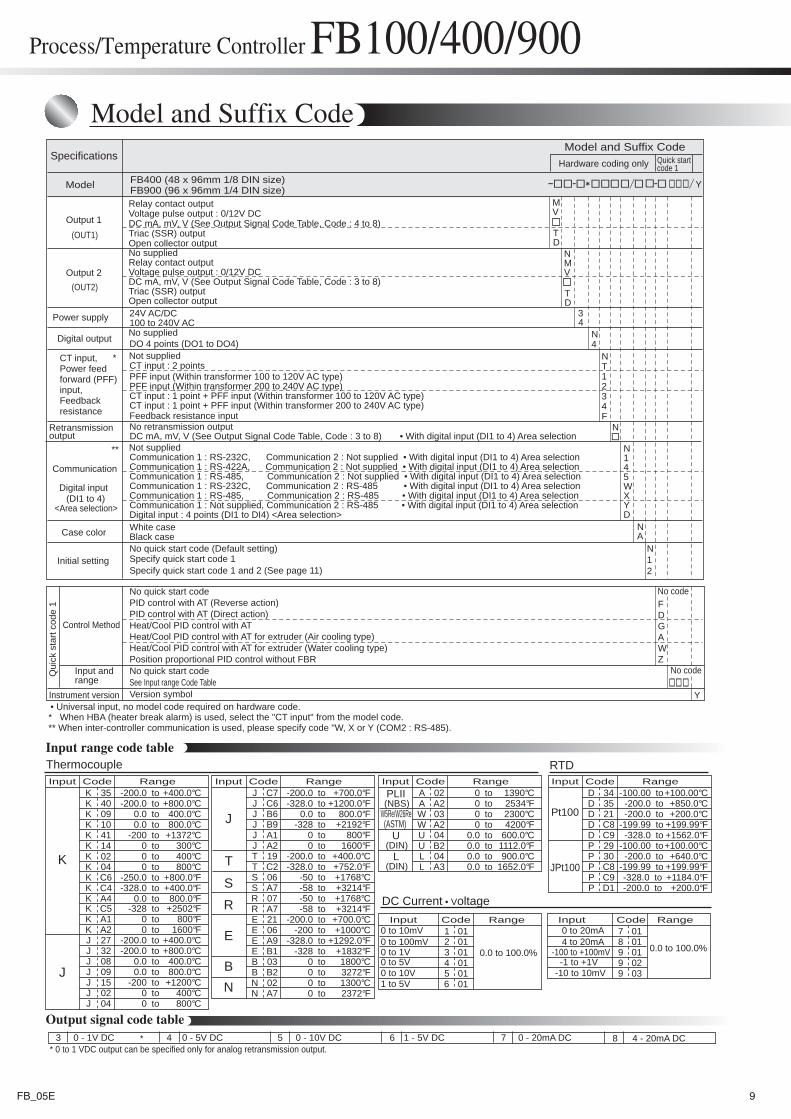
DO 4 points (DO1 to DO4)
PFF input (Within transformer 100 to 120V AC type)
Digital input : 4 points (DI1 to DI4) <Area selection>
CT input : 2 points
PFF input (Within transformer 200 to 240V AC type)CT input : 1 point + PFF input (Within transformer 100 to 120V AC type)CT input : 1 point + PFF input (Within transformer 200 to 240V AC type)Feedback resistance inputNo retransmission output
Not supplied
Not suppliedCommunication 1 : RS-232C, Communication 2 : Not supplied • With digital input (DI1 to 4) Area selection Communication 1 : RS-422A, Communication 2 : Not supplied • With digital input (DI1 to 4) Area selection Communication 1 : RS-485, Communication 2 : Not supplied • With digital input (DI1 to 4) Area selection Communication 1 : RS-232C, Communication 2 : RS-485 • With digital input (DI1 to 4) Area selection Communication 1 : RS-485, Communication 2 : RS-485 • With digital input (DI1 to 4) Area selection Communication 1 : Not supplied, Communication 2 : RS-485 • With digital input (DI1 to 4) Area selection
White caseBlack case
FDGAWZ
N
Digital output
CT input,Power feedforward (PFF)input,Feedbackresistance
Communication
Retransmissionoutput
Case color
Initial setting
Instrument version
(DI1 to 4)
(OUT1)
(OUT2)
MV
TD
NMV
N4
TD
NT1234F
N145WXYD
Specifications
Model
Model and Suffix Code
FB400 (48 x 96mm 1/8 DIN size)FB900 (96 x 96mm 1/4 DIN size)
DC mA, mV, V (See Output Signal Code Table, Code : 3 to 8) • With digital input (DI1 to 4) Area selection
Y
6 1 - 5V DC 7 0 - 20mA DC3 0 - 1V DC 8 4 - 20mA DC5 0 - 10V DC4 0 - 5V DC
Output signal code table
Input range code table
No quick start code (Default setting)
Version symbol
Specify quick start code 1 and 2 (See page 11)Specify quick start code 1
No quick start code PID control with AT (Reverse action)
No quick start code
PID control with AT (Direct action)Heat/Cool PID control with ATHeat/Cool PID control with AT for extruder (Air cooling type)Heat/Cool PID control with AT for extruder (Water cooling type)Position proportional PID control without FBR
Control Method
Input andrange
Qui
ck s
tart
code
1
See Input range Code Table
Y
No code
Hardware coding only Quick startcode 1
No code
* When HBA (heater break alarm) is used, select the "CT input" from the model code.** When inter-controller communication is used, please specify code "W, X or Y (COM2 : RS-485).
• Universal input, no model code required on hardware code.
<Area selection>
Thermocouple RTD
* 0 to 1 VDC output can be specified only for analog retransmission output.*
*
**
9FB_05E
tototototo
tototototototototototototototo
-200.0 +400.0°C-200.0 +800.0°C
0.0 400.0°C0.0 800.0°C
-200 +1372°C
0 400°C0 800°C
-250.0 +800.0°F-328.0 +400.0°F
0.0 800.0°F-328 +2502°F
0 800°F0 1600°F
-200.0 +400.0°C-200.0 +800.0°C
0.0 400.0°C0.0 800.0°C
-200 +1200°C0 400°C0 800°C
RangeCodeInputK 35K 40K 09K 10K 41
02Kto0 300°C14K
K 04K C6K C4K A4K C5K A1K A2J 27J 32J 08J 09J 15J 02J 04
K
J
totototototototototototototototototototo
-200.0 +700.0°F-328.0 +1200.0°F
0.0 800.0°F-328 +2192°F
0 800°F0 1600°F
-200.0 +400.0°C-328.0 +752.0°F
-50 +1768°C-58 +3214°F-50 +1768°C-58 +3214°F
-200.0 +700.0°C-200 +1000°C
-328.0 +1292.0°F-328 +1832°F
0 1800°C0 3272°F0 1300°C0 2372°F
RangeCodeInputJ C7J C6J B6J B9
A1JJ A2T 19T C2S 06S A7R 07R A7E 21E 06E A9E B1B 03B B2N 02N A7
J
T
SR
E
BN
totototototototo
0 1390°C0 2534°F0 2300°C0 4200°F
0.0 600.0°C0.0 1112.0°F0.0 900.0°C0.0 1652.0°F
RangeCodeInputA 02A A2W 03W A2U 04
B2UL 04L A3
totototototototototo
-100.00 +100.00°C-200.0 +850.0°C-200.0 +200.0°C
-199.99 +199.99°F-328.0 +1562.0°F
-100.00 +100.00°C-200.0 +640.0°C
-199.99 +199.99°F-328.0 +1184.0°F-200.0 +200.0°F
RangeCodeInputD 34D 35D 21D C8D C9
29PP 30P C8P C9P D1
Pt100
JPt100
W5Re/W26Re(NBS)PLII
(DIN)U
(DIN)L
(ASTM)
RangeCodeInput1 012 013 014 015 01
016
DC Current • Voltage
0 to 10mV0 to 100mV0 to 1V0 to 5V0 to 10V1 to 5V
RangeCodeInput7 018 019 019 029 03
0 to 20mA4 to 20mA
-100 to +100mV-1 to +1V
-10 to 10mV
0.0 to 100.0%0.0 to 100.0%
Process/Temperature Controller FB100/400/900Quick Start Code 2
SpecificationsInitial Setting Code
Not suppliedANSI/RKC standardMODBUS
No CT1 and CT2CT1 : CTL-6-P-N, CT2 : No useCT1 : CTL-12-S56-10L-N, CT2 : No useCT1 : CTL-6-P-N, CT2 : CTL-6-P-NCT1 : CTL-12-S56-10L-N, CT2 : CTL-12-S56-10L-N
Output logic selection
Event 1 type
Event 2 type
Event 3 type
Event 4 type
CT type
0 to 10mV DC0 to 100mV DC0 to 1V DC0 to 5V DC0 to 10V DC1 to 5V DC0 to 20mA DC4 to 20mA DC
See output logic code table.
Not suppliedSee event type code tableNot suppliedSee event type code tableNot suppliedSee event type code tableNot suppliedSee event type code tableLBA (Control loop break alarm)
Communication 1 protocol
Remote setpointinput signal
12345678
N
N
N
N
NPSTU
N12
Output Logic Code Table.
Accessory
Event Type Code Table.
5
• Quick start code 2 tells the factory to ship with each parameter preset to the values detailed as specified by the customer. Quick start code is not necessarily specified when ordering, unless the preset is requested. These parameters are software selectable items and can be re-programmed in the field via the manual.
1
Code
2
3
4
5
6
7
Output 1(OUT 1)
Output 2(OUT 2)
Digital Output 1(DO 1)
Digital Output 2(DO 2)
Digital Output 3(DO 3)
Digital Output 4(DO 4)
Control output 1 Control output 1 HBA
HBA
HBA
HBA
HBA
FAIL
Control output 1 Control output 1
Control output 2 Control output 2 Control output 2 Control output 2
Control output 1 Control output 1 Control output 1 (De-energized)
Event 1
Event 1
Event 1
Event 1
Event 1
Event 1
Event 1
Event 2
Event 2
Event 2
Event 2
Event 2
Event 2
Event 3
Event 3
Event 3
Event 3
Event 3
Event 3
Event 4
Event 4
Event 4
Event 4
FAIL(De-energized)
FAIL(De-energized)
• Energized/De-energized is configurable except for the FAIL output. (Factory default setting: Energized) • Invalid for a non-existing output/event function.(Caution) • When used as heating/cooling control/position proportioning control, select any code of 1 to 4.
* Please specify "8" when the remote setpoint input signal is not used.
CodeEvent typeDeviation HighDeviation LowDeviation High/LowBandDeviation High with Alarm HoldDeviation Low with Alarm Hold
Process High with Alarm HoldProcess Low with Alarm Hold
ABCDEF
Deviation High/Low with Alarm Hold
Deviation High with Alarm Re-HoldDeviation Low with Alarm Re-HoldDeviation High/Low with Alarm Re-Hold
Process HighProcess Low
GHJKLQRT
Set value HighSet value LowMV value HighMV value LowCool side MV value HighCool side MV value Low
VW1234
Model CodeTerminal cover
(FB900 uses 2 unit)
Max
.63
Max.70
Max.68
2-M4
5959
±0.5
50
Mounting dimension
* Supplied when power feed forward function is specified.
* When ordering transformer for replacement, please specify one of the following model codes. 100 to 120V AC type : PFT-01 200 to 240V AC type : PFT-02
(For Power feed forward input)
±1
±0.2
Model code
Current transformer for heater break alarm (HBA)
CTL-6-P-N (0 to 30A)CTL-12-S56-10L-N (0 to 100A)
(Sold separately) (Sold separately)
Front cover (Sold separately)
CTL-6-P-N
CTL-12-S56-10L-N
(Unit : mm)
φ 5.8
14.525
2110
Approx.130
φ 12M3 Depth 4
40
30 40
7.5
15
Approx.100
(Unit : mm)
FB100
KFB400-58KCA100-517
PV
ALM2
RH400
FB400/900FB100
FB900 FB400
FB100FB900 FB400
FB900FB400FB100
KF4-34KRB100-36
KF9-35
Type
Model CodeType
10 FB_05E
Process/Temperature Controller FB100/400/900
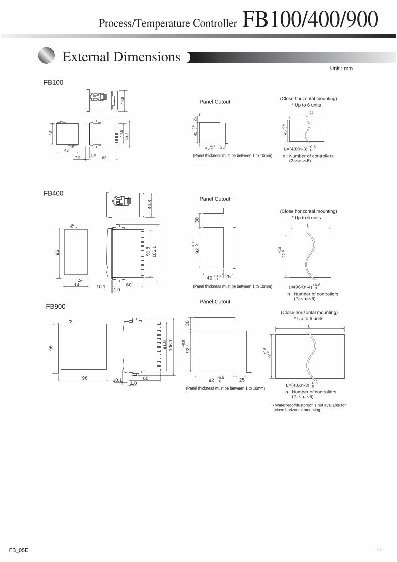
External DimensionsUnit : mm
(Panel thickness must be between 1 to 10mm)
(Panel thickness must be between 1 to 10mm)
(Panel thickness must be between 1 to 10mm)
Panel Cutout
Panel Cutout
Panel Cutout
(Close horizontal mounting)* Up to 6 units
(Close horizontal mounting)* Up to 6 units
(Close horizontal mounting)* Up to 6 units
L=(96Xn-4)
n : Number of controllers (2=<n=<6)
n : Number of controllers (2=<n=<6)
+0.8 0
L=(48Xn-3)+0.6 0
2592 +0.80
92+0
.80
30FB400
FB100
2545 +0.60
92+0
.80
30
FB900
48
96 91.8
106.
144
.8
10.1 1.060
91.8
106.
1
10.1 1.06096
96
L
92+0
.8 0
L
92+0
.8 0
• Waterproof/dustproof is not available for close horizontal mounting.
2545+0.60
45+0
.6 025
+0.60L
45+0
.6 0
7.9 1.063
48
44.8
59.3
44.8
48
L=(48Xn-3)
n : Number of controllers (2=<n=<6)
+0.6 0
11FB_05E
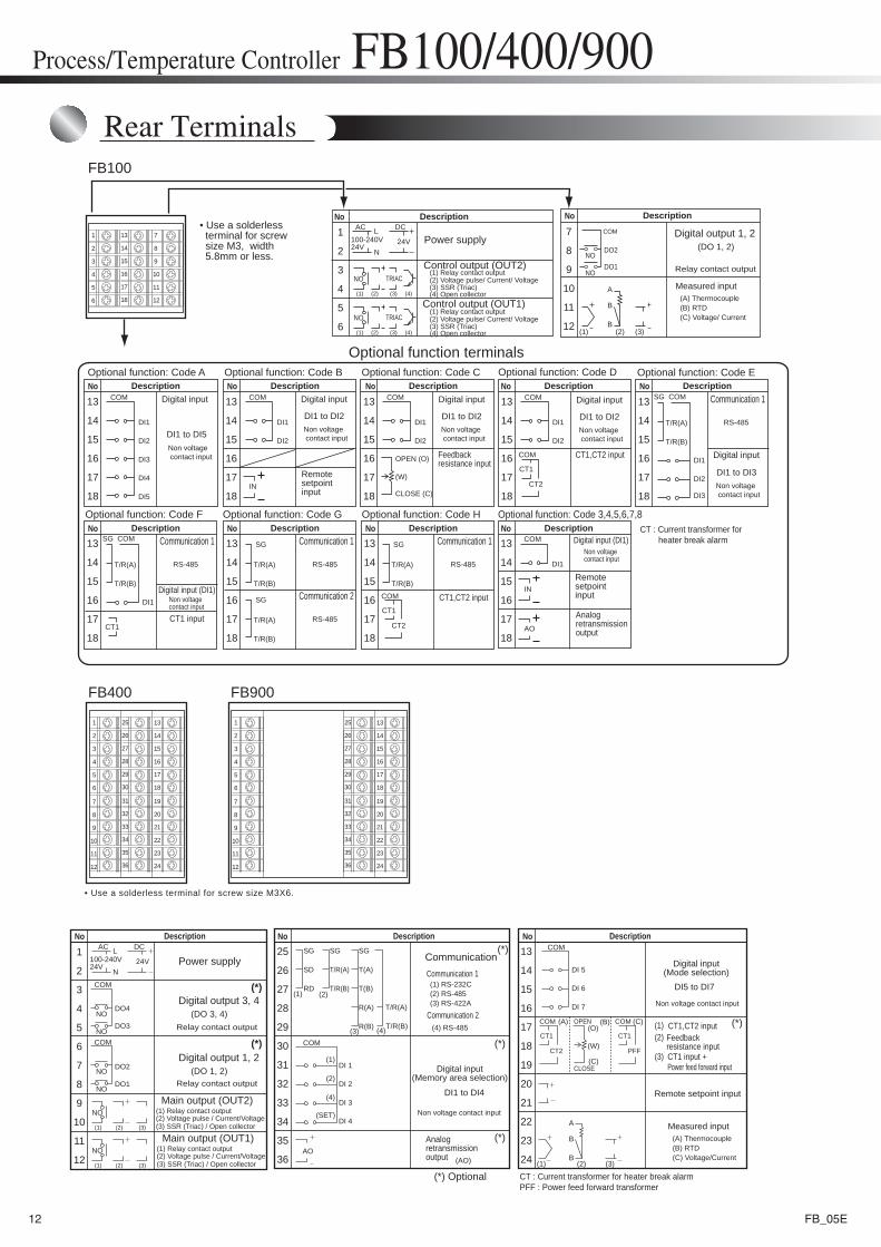
Rear Terminals
Process/Temperature Controller FB100/400/900
CT1
CT2
COM
COM
(1)
(2)
(4)
(SET)
SG
T(A)
T(B)
R(A)
R(B)
SG
T/R(A)
T/R(B)
(3)
(2)
SG
SD
RD(1)
25
26
27
28
29
30
31
32
33
35
34
36
13
14
15
16
17
18
19
20
21
23
22
24(AO)
CT1
PFF
COM
(1) (2) (3)
A
B
B
(*)
(*)
(*)
(*)
(*)
(*)
(*) Optional
Non voltage contact input
COM
DI 5
DI 6
DI 7
DI 1
DI 2
DI 3
DI 4
(O)
(W)
(C)
(A) (B) (C)
1
2
3
4
5
6
7
8
9
11
10
12
AC
100-240V24V
DC
24VL
N
NO
NO
NO
(1) (2) (3)
NO
(1) (2) (3)
NO
NODO4
COM
COM
DO3
DO2
DO1
(DO 3, 4)Relay contact output
T/R(A)
T/R(B)(4)
AO
DescriptionNo DescriptionNo
Power supply
Digital output 3, 4
(DO 1, 2)Relay contact output
Digital output 1, 2
Communication
(2) Voltage pulse / Current/Voltage(1) Relay contact output
(3) SSR (Triac) / Open collector
(A) Thermocouple(B) RTD(C) Voltage/Current
CT1,CT2 inputFeedback resistance inputCT1 input +Power feed forward input
(1)(2)
(3)
(1) RS-232C(2) RS-485(3) RS-422A
(4) RS-485
Digital input(Memory area selection)
Analogretransmissionoutput
Remote setpoint input
Measured input
Main output (OUT2)
(2) Voltage pulse / Current/Voltage(1) Relay contact output
(3) SSR (Triac) / Open collector
Main output (OUT1)
Communication 1
Communication 2
DI1 to DI4
Non voltage contact input
Digital input(Mode selection)
DI5 to DI7
DescriptionNo
OPEN
CLOSE
CT : Current transformer for heater break alarmPFF : Power feed forward transformer
7
8
9
10
11
12
1
2
3
4
5
6
19
20
21
22
23
24
13
14
15
16
17
18
31
32
33
34
35
36
25
26
27
28
29
30
7
8
9
10
11
12
1
2
3
4
5
6
19
20
21
22
23
24
13
14
15
16
17
18
31
32
33
34
35
36
25
26
27
28
29
30
• Use a solderless terminal for screw size M3X6.
FB900FB400
1
2
3
4
5
6
7
8
9
10
11
12
13
14
15
16
17
18
FB100
7
8
9
10
11
12 (1) (2) (3)
A
B
B
1
2
3
4
5
6
AC
100-240V24V
DC
24VL
N NO
NODO1
DO2
13
14
15
16
17
18
COM SG
T/R(A)
T/R(B)
CT1
CT2
COM
CT1
DI1
DI2
DI3
DI4
DI5IN
13
14
15
16
17
18
COM
DI1
DI2
COM
DI1
DI2
DI3
COM
IN
AO
13
14
15
16
17
18
COM
DI1
13
14
15
16
17
18
COM
DI1
DI2
13
14
15
16
17
18
COM
DI1
DI2
13
14
15
16
17
18
SG
T/R(A)
T/R(B)
COM
DI1
13
14
15
16
17
18
SG
T/R(A)
T/R(B)
SG
T/R(A)
T/R(B)
13
14
15
16
17
18
SG
T/R(A)
T/R(B)
13
14
15
16
17
18
CT1
CT2
COM
NO
(1) (2) (3)
TRIAC
(4)
NO
(1) (2) (3)
TRIAC
(4)
OPEN (O)
(W)
CLOSE (C)
Optional function terminalsOptional function: Code A
Optional function: Code 3,4,5,6,7,8Optional function: Code F
Optional function: Code B Optional function: Code C
Non voltage contact input
DescriptionNo DescriptionNo
Power supply(DO 1, 2)
Relay contact output
Digital output 1, 2
(2) Voltage pulse/ Current/ Voltage(1) Relay contact output
(3) SSR (Triac)(4) Open collector
(2) Voltage pulse/ Current/ Voltage(1) Relay contact output
(3) SSR (Triac)(4) Open collector
(A) Thermocouple(B) RTD(C) Voltage/ Current
Digital input
Measured input
Control output (OUT2)
Control output (OUT1)
DI1 to DI5
Non voltage contact input
Digital input
DI1 to DI3
Non voltage contact input
Digital input
DI1 to DI2Non voltage contact input
Digital input
DI1 to DI2Non voltage contact input
Digital input
DI1 to DI2
Remotesetpointinput
CT1,CT2 input
CT1,CT2 input
Feedback resistance input
Non voltagecontact input
Digital input (DI1)
Communication 1
RS-485
CT1 input
Non voltagecontact input
Digital input (DI1)
Remotesetpointinput
Analogretransmissionoutput
Optional function: Code D
Optional function: Code G Optional function: Code H
• Use a solderless terminal for screw size M3, width 5.8mm or less.
DescriptionNo DescriptionNo DescriptionNo DescriptionNo
DescriptionNo DescriptionNo DescriptionNo DescriptionNo
DescriptionNoOptional function: Code E
Communication 1
RS-485
Communication 1
RS-485
Communication 2
RS-485
Communication 1
RS-485
CT : Current transformer for heater break alarm
12 FB_05E