Embed Size (px)
Citation preview
PDR 900
Series 900 vacuum controller
RS232 / RS485
Operation Manual
P/N: 100017303 PDR900-12, Operation Manual Revision: A, November 2008
(505)872-0037idealvac.com
idealvac.com
Extent of the Warranty MKS Instruments, Inc., HPS™ Products Inc. and MKS Denmark ApS warrants the PDR900 Vacuum Controller and its accessories to be free from defects in materials and workmanship for one (1) year from the date of shipment by HPS™ or authorized representative to the original purchaser (PURCHASER). Any product or parts of the product repaired or replaced by HPS™ under this warranty are warranted only for the remaining unexpired part of its one (1) year original warranty period. After expiration of the applicable warranty period, the PURCHASER shall be charged HPS™’ current prices for parts and labor, plus any transportation for any repairs or replacement. ALL EXPRESS AND IMPLIED WARRANTIES, INCLUDING THE IMPLIED WARRANTIES OF MERCHANTABILITY AND FITNESS FOR A PARTICULAR PURPOSE, ARE LIMITED TO THE WARRANTY PERIOD. NO WARRANTIES, EXPRESS OR IMPLIED, WILL APPLY AFTER THIS PERIOD. Warranty Service The obligations of HPS™ under this warranty shall be at its option: (1) to repair, replace, or adjust the product so that it meets applicable product specifications published by HPS™ or (2) to refund the purchase price. What Is Not Covered The product is subject to above terms only if located in the country of the seller from whom the product was purchased. The above warranties do not apply to: I. Damages or malfunctions due to failure to provide reasonable and necessary maintenance in accordance with HPS™ operating instructions. II. Damages or malfunctions due to chemical or electrolytic influences or use of the product in working environments outside the specification. III. Fuses and all expendable items which by their nature or limited lifetime may not function for a year. If such items fail to give reasonable service for a reasonable period of time within the warranty period of the product; they will, at the option of HPS™, be repaired or replaced. IV. Defects or damages caused by modifications and repairs effected by the original PURCHASER or third parties not authorized in the manual. Condition of Returned Products HPSTM will not accept for repair, replacement, or credit any product which is asserted to be defective by the PURCHASER, or any product for which paid or unpaid service is desired, if the product is contaminated with potentially corrosive, reactive, harmful, or radioactive materials, gases, or chemicals. When products are used with toxic chemicals, or in an atmosphere that is dangerous to the health of humans, or is environmentally unsafe, it is the responsibility of the PURCHASER to have the product cleaned by an independent agency skilled and approved in the handling and cleaning of contaminated materials before the product will be accepted by HPS
TM for repair and/or replacement.
In the course of implementing this policy, HPSTM
Customer Service Personnel may inquire of the PURCHASER whether the product has been contaminated with or exposed to potentially corrosive, reactive, harmful, or radioactive materials, gases, or chemicals when the PURCHASER requests a return authorization. Notwithstanding such inquiries, it is the responsibility of the PURCHASER to ensure that no products are returned to HPS™ which have been contaminated in the aforementioned manner. Other Rights and Remedies I. These remedies are exclusive. HPS™ SHALL NOT BE LIABLE FOR CONSEQUENTIAL DAMAGES, FOR ANTICIPATED OR LOST PROFITS, INCIDENTAL DAMAGES OR LOSS OF TIME, OR OTHER LOSSES INCURRED BY THE PURCHASER OR BY ANY THIRD PARTY IN CONNECTION WITH THE PRODUCT COVERED BY THIS WARRANTY, OR OTHERWISE. Some states do not allow exclusion or limitation of incidental or consequential damage or do not allow the limitation on how long an implied warranty lasts. If such laws apply, the limitations or exclusions expressed herein may not apply to PURCHASER. II. Unless otherwise explicitly agreed in writing, it is understood that these are the only written warranties given by HPS™. Any statements made by any persons, including representatives of HPS™, which are inconsistent or in conflict with the terms of the warranty shall not be binding on HPSTM unless reduced to writing and approved by an authorized officer of HPS™. III. This warranty gives PURCHASER specific legal rights, and PURCHASER may also have other rights which vary from state to state. IV. For HPS™ products sold outside of the U.S., contact your MKS representative for warranty information and service. Warranty Performance To obtain warranty satisfaction, contact the following: US & ASIA: MKS Instruments, Inc., HPS™ Products, Inc., 5330 Sterling Drive, Boulder, CO 80301, USA, Phone: (303) 449-9861.
EUROPE: MKS Denmark ApS, Ndr. Strandvej 119G, DK3150 Hellebaek, Denmark, Phone: +45 44 92 92 99, E-mail: [email protected]
Part number: PDR900-12-_ _ _ _ _ _ _ _ _
Serial number: _ _ _ _ _ _ _ _ _ _ _ _ _ _
Please fill in these numbers and have them readily available when calling for service or additional information. The part number can be found on your packing slip, and both the part number and serial number are located on the side of the housing.
© 2006 MKS Instruments. All rights reserved. Trademarks used in this manual: HPS™, MicroPirani™, DualTrans™ and Quattro™ are trademarks of MKS Instruments Inc. Windows
®
is a trademark of Microsoft Corporation
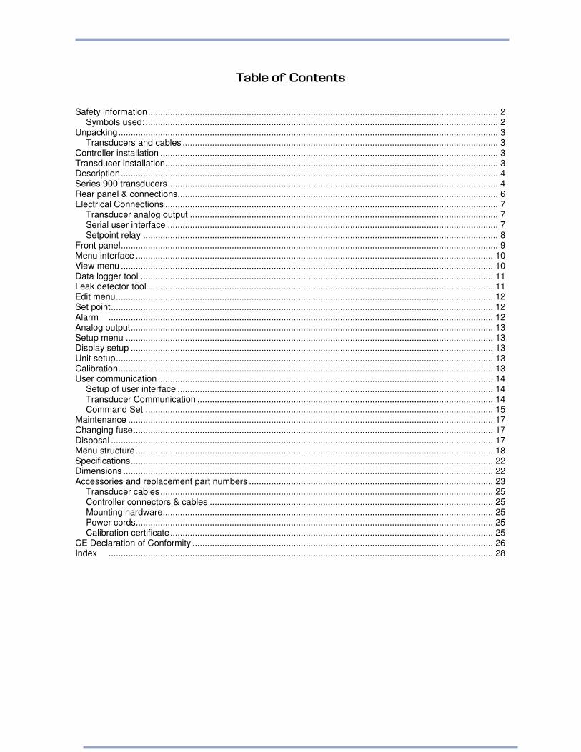
Table of Contents Safety information.............................................................................................................................................. 2
Symbols used: ............................................................................................................................................... 2 Unpacking.......................................................................................................................................................... 3
Transducers and cables ................................................................................................................................ 3 Controller installation ......................................................................................................................................... 3 Transducer installation....................................................................................................................................... 3 Description......................................................................................................................................................... 4 Series 900 transducers...................................................................................................................................... 4 Rear panel & connections.................................................................................................................................. 6 Electrical Connections ....................................................................................................................................... 7
Transducer analog output ............................................................................................................................. 7 Serial user interface ...................................................................................................................................... 7 Setpoint relay ................................................................................................................................................ 8
Front panel......................................................................................................................................................... 9 Menu interface ................................................................................................................................................. 10 View menu ....................................................................................................................................................... 10 Data logger tool ............................................................................................................................................... 11 Leak detector tool ............................................................................................................................................ 11 Edit menu......................................................................................................................................................... 12 Set point........................................................................................................................................................... 12 Alarm ............................................................................................................................................................ 12 Analog output................................................................................................................................................... 13 Setup menu ..................................................................................................................................................... 13 Display setup ................................................................................................................................................... 13 Unit setup......................................................................................................................................................... 13 Calibration........................................................................................................................................................ 13 User communication ........................................................................................................................................ 14
Setup of user interface ................................................................................................................................ 14 Transducer Communication ........................................................................................................................ 14 Command Set ............................................................................................................................................. 15
Maintenance .................................................................................................................................................... 17 Changing fuse.................................................................................................................................................. 17 Disposal ........................................................................................................................................................... 17 Menu structure................................................................................................................................................. 18 Specifications................................................................................................................................................... 22 Dimensions ...................................................................................................................................................... 22 Accessories and replacement part numbers ................................................................................................... 23
Transducer cables....................................................................................................................................... 25 Controller connectors & cables ................................................................................................................... 25 Mounting hardware...................................................................................................................................... 25 Power cords................................................................................................................................................. 25 Calibration certificate................................................................................................................................... 25
CE Declaration of Conformity .......................................................................................................................... 26 Index ............................................................................................................................................................ 28

For more information contact: MKS Denmark ApS Ndr. Strandvej 119G DK-3150 Hellebæk Denmark Tel: +45 44 92 92 99 – Fax: +45 44 92 94 99 Email: [email protected] MKS Instruments, HPS Products 5330 Sterling Dr. CO-80301 Boulder USA Tel: 303 449 9861 - Fax: 303 449 2003
PDR900 Operation manual
2
Safety information: Symbols used:
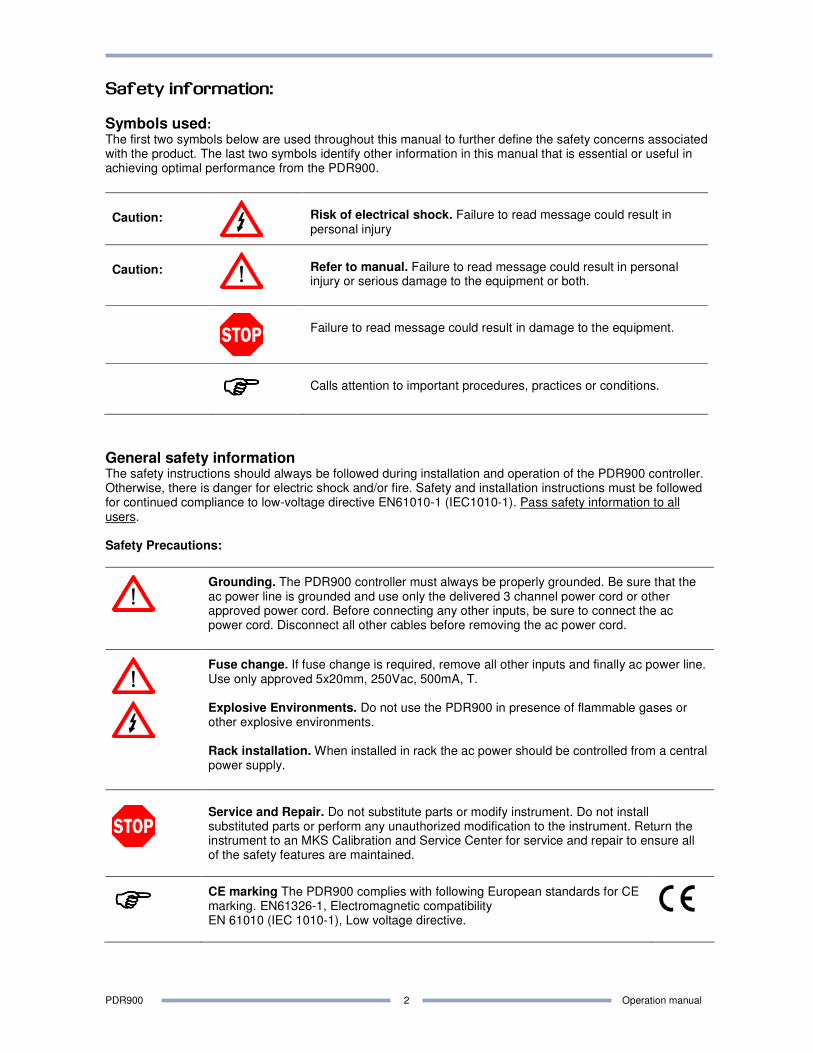
The first two symbols below are used throughout this manual to further define the safety concerns associated with the product. The last two symbols identify other information in this manual that is essential or useful in achieving optimal performance from the PDR900.
Caution:
Risk of electrical shock. Failure to read message could result in personal injury
Caution:
Refer to manual. Failure to read message could result in personal injury or serious damage to the equipment or both.
Failure to read message could result in damage to the equipment.
���� Calls attention to important procedures, practices or conditions.
General safety information The safety instructions should always be followed during installation and operation of the PDR900 controller. Otherwise, there is danger for electric shock and/or fire. Safety and installation instructions must be followed for continued compliance to low-voltage directive EN61010-1 (IEC1010-1). Pass safety information to all users. Safety Precautions:
Grounding. The PDR900 controller must always be properly grounded. Be sure that the ac power line is grounded and use only the delivered 3 channel power cord or other approved power cord. Before connecting any other inputs, be sure to connect the ac power cord. Disconnect all other cables before removing the ac power cord.
Fuse change. If fuse change is required, remove all other inputs and finally ac power line. Use only approved 5x20mm, 250Vac, 500mA, T. Explosive Environments. Do not use the PDR900 in presence of flammable gases or other explosive environments. Rack installation. When installed in rack the ac power should be controlled from a central power supply.
Service and Repair. Do not substitute parts or modify instrument. Do not install substituted parts or perform any unauthorized modification to the instrument. Return the instrument to an MKS Calibration and Service Center for service and repair to ensure all of the safety features are maintained.
����
CE marking The PDR900 complies with following European standards for CE marking. EN61326-1, Electromagnetic compatibility EN 61010 (IEC 1010-1), Low voltage directive.
PDR900 Operation manual
3
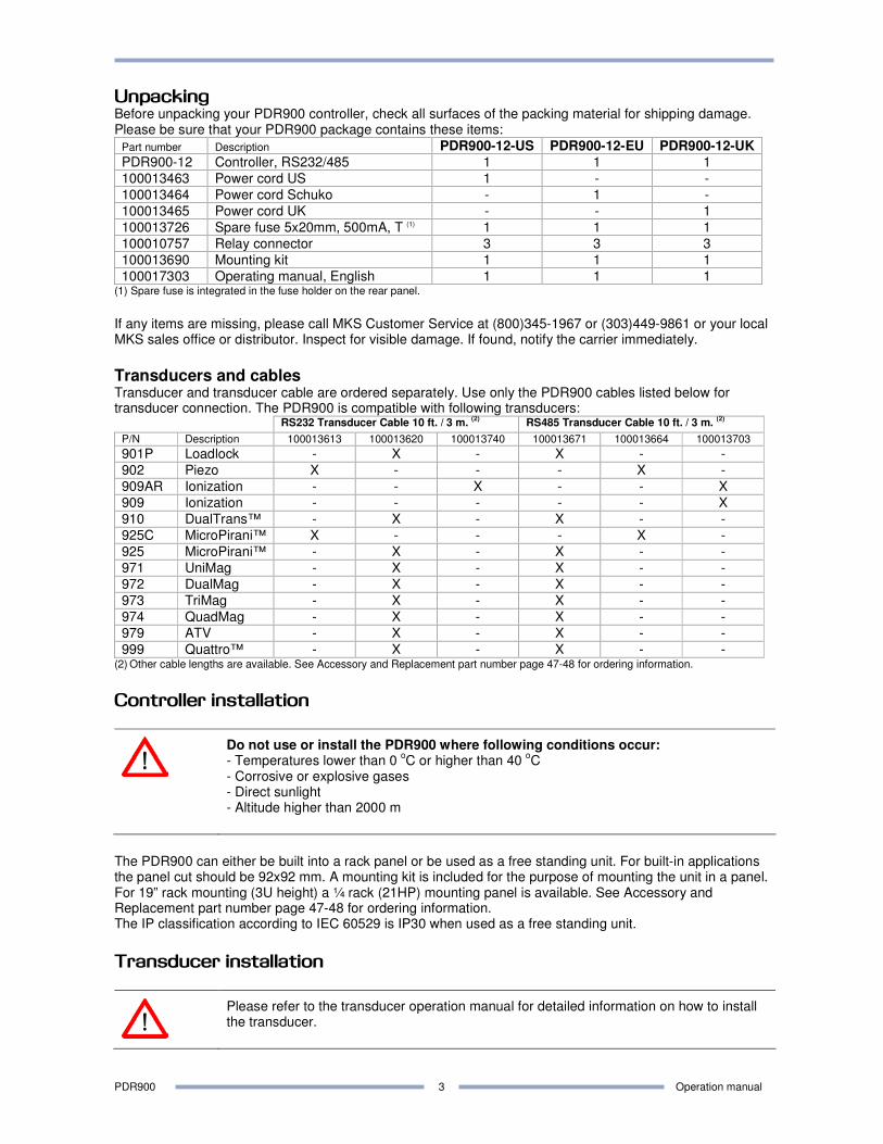
Unpacking Before unpacking your PDR900 controller, check all surfaces of the packing material for shipping damage. Please be sure that your PDR900 package contains these items:
Part number Description PDR900-12-US PDR900-12-EU PDR900-12-UK
PDR900-12 Controller, RS232/485 1 1 1
100013463 Power cord US 1 - -
100013464 Power cord Schuko - 1 -
100013465 Power cord UK - - 1
100013726 Spare fuse 5x20mm, 500mA, T (1) 1 1 1
100010757 Relay connector 3 3 3
100013690 Mounting kit 1 1 1
100017303 Operating manual, English 1 1 1 (1) Spare fuse is integrated in the fuse holder on the rear panel.
If any items are missing, please call MKS Customer Service at (800)345-1967 or (303)449-9861 or your local MKS sales office or distributor. Inspect for visible damage. If found, notify the carrier immediately.
Transducers and cables Transducer and transducer cable are ordered separately. Use only the PDR900 cables listed below for transducer connection. The PDR900 is compatible with following transducers:
RS232 Transducer Cable 10 ft. / 3 m. (2) RS485 Transducer Cable 10 ft. / 3 m.
(2)
P/N Description 100013613 100013620 100013740 100013671 100013664 100013703
901P Loadlock - X - X - -
902 Piezo X - - - X -
909AR Ionization - - X - - X
909 Ionization - - - - - X
910 DualTrans™ - X - X - -
925C MicroPirani™ X - - - X -
925 MicroPirani™ - X - X - -
971 UniMag - X - X - -
972 DualMag - X - X - -
973 TriMag - X - X - -
974 QuadMag - X - X - -
979 ATV - X - X - -
999 Quattro™ - X - X - - (2)
Other cable lengths are available. See Accessory and Replacement part number page 47-48 for ordering information.
Controller installation
Do not use or install the PDR900 where following conditions occur: - Temperatures lower than 0
oC or higher than 40
oC
- Corrosive or explosive gases - Direct sunlight - Altitude higher than 2000 m
The PDR900 can either be built into a rack panel or be used as a free standing unit. For built-in applications the panel cut should be 92x92 mm. A mounting kit is included for the purpose of mounting the unit in a panel. For 19” rack mounting (3U height) a ¼ rack (21HP) mounting panel is available. See Accessory and Replacement part number page 47-48 for ordering information. The IP classification according to IEC 60529 is IP30 when used as a free standing unit.
Transducer installation
Please refer to the transducer operation manual for detailed information on how to install the transducer.
PDR900 Operation manual
4
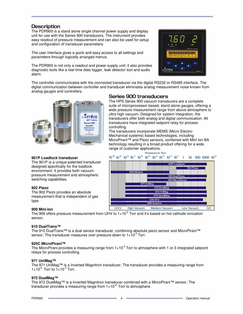
Description The PDR900 is a stand alone single channel power supply and display unit for use with the Series 900 transducers. The instrument provides easy readout of pressure measurement and can also be used for setup and configuration of transducer parameters. The user interface gives a quick and easy access to all settings and parameters through logically arranged menus. The PDR900 is not only a readout and power supply unit; it also provides diagnostic tools like a real time data logger, leak detector tool and audio alarm. The controller communicates with the connected transducer via the digital RS232 or RS485 interface. The digital communication between controller and transducer eliminates analog measurement noise known from analog gauges and controllers.
Series 900 transducers The HPS Series 900 vacuum transducers are a complete suite of microprocessor based, stand alone gauges, offering a wide pressure measurement range from above atmosphere to ultra high vacuum. Designed for system integration, the transducers offer both analog and digital communication. All transducers have integrated setpoint relay for process controlling. The transducers incorporate MEMS (Micro Electro-Mechanical systems) based technologies, including MicroPirani™ and Piezo sensors, combined with Mini Ion BA technology resulting in a broad product offering for a wide range of customer applications.
901P Loadlock transducer The 901P is a unique patented transducer designed specifically for the loadlock environment. It provides both vacuum pressure measurement and atmospheric switching capabilities. 902 Piezo The 902 Piezo provides an absolute measurement that is independent of gas type. 909 Mini-Ion The 909 offers pressure measurement from UHV to 1×10
-2 Torr and it’s based on hot cathode ionization
sensor. 910 DualTrans™ The 910 DualTrans™ is a dual sensor transducer, combining absolute piezo sensor and MicroPirani™ sensor. The transducer measures over pressure down to 1×10
-5 Torr.
925C MicroPirani™ The MicroPirani provides a measuring range from 1×10
-5 Torr to atmosphere with 1 or 3 integrated setpoint
relays for process controlling. 971 UniMag™ The 971 UniMag™ is a Inverted Magnitron transducer. The transducer provides a measuring range from 1×10
-8 Torr to 1×10
-2 Torr.
972 DualMag™ The 972 DualMag™ is a Inverted Magnitron transducer combined with a MicroPirani™ sensor. The transducer provides a measuring range from 1×10
-8 Torr to atmosphere.
10-10
10-9
10-8
10-7
10-6
10-5
10-4
10-3
10-2
10-1
10+4
1 10 100 1000
Pressure in Torr
901P Loadlock
910 DualTrans
925 MicroPirani
902 Piezo
971 UniMag
972 DualMag
909 MiniIon
979 ATV
999 Quattro
973 TriMag
974 QuadMag
PDR900 Operation manual
5
973 TriMag™ The 973 TriMag™ is a Inverted Magnitron transducer combined with a MicroPirani™ sensor and an absolute piezo sensor. The transducer provides a measuring range from 1×10
-8 Torr to atmosphere.
974 QuadMag™ The 974 QuadMag™ is a Inverted Magnitron transducer combined with a MicroPirani™ sensor and an differential piezo sensor. The transducer provides a measuring range from 1×10
-8 Torr to atmosphere.
979 ATV The 979 combines the MicroPirani and the Mini ion BA gauge and provide a wide measuring range from UHV to atmosphere. 999 Quattro™ The 999 Quattro™ is based on three sensor types with the functionally of four sensors, providing a pressure measurement from UHV to 1000 Torr, combined with atmospheric switching capabilities.
PDR900 Operation manual
6
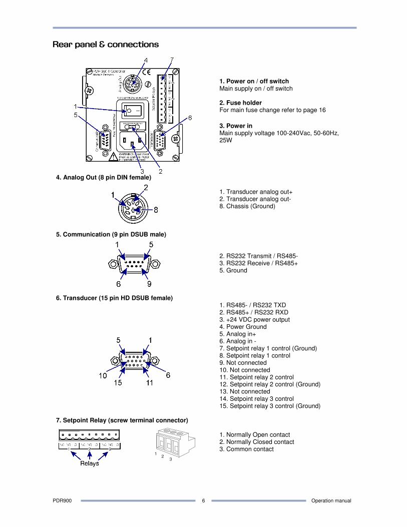
Rear panel & connections
1. Power on / off switch Main supply on / off switch 2. Fuse holder For main fuse change refer to page 16 3. Power in Main supply voltage 100-240Vac, 50-60Hz, 25W
4. Analog Out (8 pin DIN female)
1. Transducer analog out+ 2. Transducer analog out- 8. Chassis (Ground)
5. Communication (9 pin DSUB male)
2. RS232 Transmit / RS485- 3. RS232 Receive / RS485+ 5. Ground
6. Transducer (15 pin HD DSUB female)
1. RS485- / RS232 TXD 2. RS485+ / RS232 RXD 3. +24 VDC power output 4. Power Ground 5. Analog in+ 6. Analog in - 7. Setpoint relay 1 control (Ground) 8. Setpoint relay 1 control 9. Not connected 10. Not connected 11. Setpoint relay 2 control 12. Setpoint relay 2 control (Ground) 13. Not connected 14. Setpoint relay 3 control 15. Setpoint relay 3 control (Ground)
7. Setpoint Relay (screw terminal connector)
1. Normally Open contact 2. Normally Closed contact 3. Common contact
12
3
PDR900 Operation manual
7
Electrical Connections
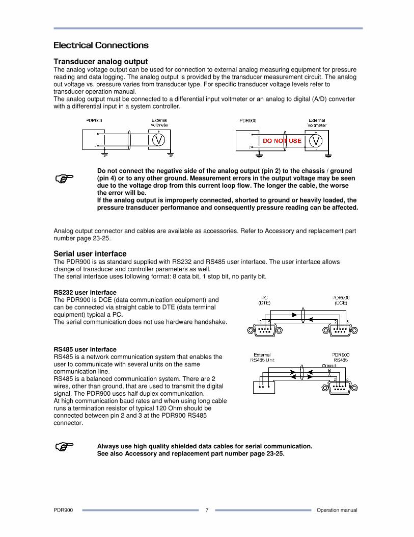
Transducer analog output The analog voltage output can be used for connection to external analog measuring equipment for pressure reading and data logging. The analog output is provided by the transducer measurement circuit. The analog out voltage vs. pressure varies from transducer type. For specific transducer voltage levels refer to transducer operation manual. The analog output must be connected to a differential input voltmeter or an analog to digital (A/D) converter with a differential input in a system controller.
����
Do not connect the negative side of the analog output (pin 2) to the chassis / ground (pin 4) or to any other ground. Measurement errors in the output voltage may be seen due to the voltage drop from this current loop flow. The longer the cable, the worse the error will be. If the analog output is improperly connected, shorted to ground or heavily loaded, the pressure transducer performance and consequently pressure reading can be affected.
Analog output connector and cables are available as accessories. Refer to Accessory and replacement part number page 23-25.
Serial user interface The PDR900 is as standard supplied with RS232 and RS485 user interface. The user interface allows change of transducer and controller parameters as well. The serial interface uses following format: 8 data bit, 1 stop bit, no parity bit.
RS232 user interface The PDR900 is DCE (data communication equipment) and can be connected via straight cable to DTE (data terminal equipment) typical a PC. The serial communication does not use hardware handshake.
RS485 user interface RS485 is a network communication system that enables the user to communicate with several units on the same communication line. RS485 is a balanced communication system. There are 2 wires, other than ground, that are used to transmit the digital signal. The PDR900 uses half duplex communication. At high communication baud rates and when using long cable runs a termination resistor of typical 120 Ohm should be connected between pin 2 and 3 at the PDR900 RS485 connector.
����
Always use high quality shielded data cables for serial communication. See also Accessory and replacement part number page 23-25.
PDR900 Operation manual
8
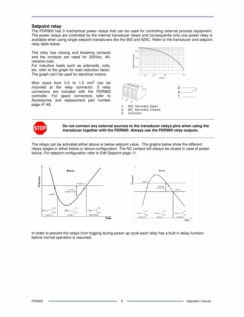
Setpoint relay The PDR900 has 3 mechanical power relays that can be used for controlling external process equipment. The power relays are controlled by the internal transducer relays and consequently only one power relay is available when using single setpoint transducers like the 902 and 925C. Refer to the transducer and setpoint relay table below. The relay has closing and breaking contacts and the contacts are rated for 250Vac, 4A, resistive load. For inductive loads such as solenoids, coils, etc. refer to the graph for load reduction factor. The graph can’t be used for electrical motors. Wire sized from 0.5 to 1.5 mm
2 can be
mounted at the relay connector. 3 relay connectors are included with the PDR900 controller. For spare connectors refer to Accessories and replacement part number page 47-48.
1. NO, Normally Open 2. NC, Normally Closed 3. Common
13
2
Do not connect any external sources to the transducer relays pins when using the transducer together with the PDR900. Always use the PDR900 relay outputs.
The relays can be activated either above or below setpoint value. The graphs below show the different relays stages in either below or above configuration. The NC contact will always be closed in case of power failure. For setpoint configuration refer to Edit Setpoint page 11.
In order to prevent the relays from trigging during power up cycle each relay has a built in delay function before normal operation is resumed.
12
3
PDR900 Operation manual
9
Searching for
transducer...
901P LOADLOCK
MP readout PR1
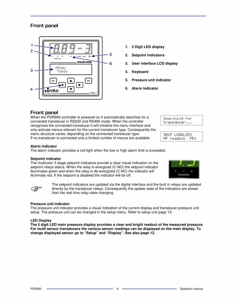
Front panel
1. 5 Digit LED display 2. Setpoint indicators
3. User interface LCD display
4. Keyboard
5. Pressure unit indicator
6. Alarm indicator
Front panel When the PDR900 controller is powered on it automatically searches for a connected transducer in RS232 and RS485 mode. When the controller recognizes the connected transducer it will initialize the menu interface and only activate menus relevant for the current transducer type. Consequently the menu structure varies, depending on the connected transducer type. If no transducer is connected only a limited number of menus are available. Alarm indicator The alarm indicator provides a red light when the low or high alarm limit is exceeded. Setpoint indicator The multicolor 3 stage setpoint indicators provide a clear visual indication on the setpoint relays status. When the relay is energized (C-NO) the setpoint indicator illuminates green and when the relay is de-energized (C-NC) the indicator will illuminate red. If the setpoint is disabled the indicator will be off.
� The setpoint indicators are updated via the digital interface and the built in relays are updated directly by the transducer relays. Consequently the update rates of the indicators are slower than the real time relay state changing.
Pressure unit indicator The pressure unit indicator provides a visual indication of the current display and transducer pressure unit setup. The pressure unit can be changed in the setup menu. Refer to setup unit page 13. LED Display The 5 digit LED main pressure display provides a clear and bright readout of the measured pressure. For multi sensor transducers the various sensor readings can be displayed on the main display. To change displayed sensor go to “Setup” and “Display”. See also page 13.
PDR900 Operation manual
10
ÆÆÆÆÆÆÆÆÆø
-5-4-3-2-1 0+1+2
Setpoint 1:Clear
Value: 1.23E-4
Firmware Version
2.00
Time On
000089 hours
Model: 901P
LOADLOCK
MP: 7.80E+2
PZ: 1.00E-1
CMB: 7.62E+2
Max.Pr. 7.80E+2
Min.Pr. 1.23E-4
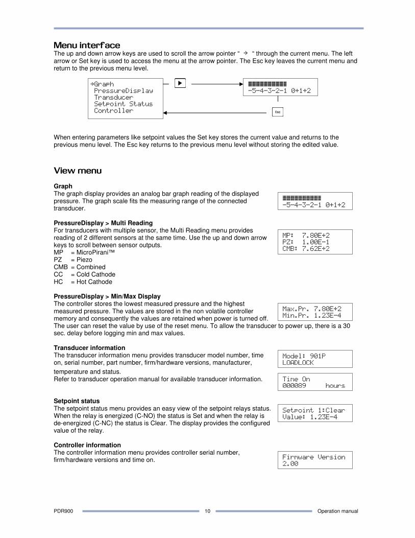
Menu interface The up and down arrow keys are used to scroll the arrow pointer “ ¨å “ through the current menu. The left arrow or Set key is used to access the menu at the arrow pointer. The Esc key leaves the current menu and return to the previous menu level.
When entering parameters like setpoint values the Set key stores the current value and returns to the previous menu level. The Esc key returns to the previous menu level without storing the edited value.
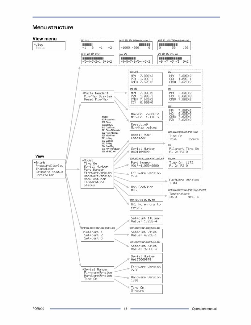
View menu Graph The graph display provides an analog bar graph reading of the displayed pressure. The graph scale fits the measuring range of the connected transducer. PressureDisplay > Multi Reading For transducers with multiple sensor, the Multi Reading menu provides reading of 2 different sensors at the same time. Use the up and down arrow keys to scroll between sensor outputs. MP = MicroPirani™ PZ = Piezo CMB = Combined CC = Cold Cathode HC = Hot Cathode PressureDisplay > Min/Max Display The controller stores the lowest measured pressure and the highest measured pressure. The values are stored in the non volatile controller memory and consequently the values are retained when power is turned off. The user can reset the value by use of the reset menu. To allow the transducer to power up, there is a 30 sec. delay before logging min and max values. Transducer information The transducer information menu provides transducer model number, time on, serial number, part number, firm/hardware versions, manufacturer,
temperature and status. Refer to transducer operation manual for available transducer information. Setpoint status The setpoint status menu provides an easy view of the setpoint relays status. When the relay is energized (C-NO) the status is Set and when the relay is de-energized (C-NC) the status is Clear. The display provides the configured value of the relay. Controller information The controller information menu provides controller serial number, firm/hardware versions and time on.
ÆÆÆÆÆÆÆÆÆø
-5-4-3-2-1 0+1+2
åGraph
PressureDisplay
Transducer
Setpoint Status
Controller
PDR900 Operation manual
11
Time: 00:00:10
CMB:4.56E-3 Torr
Datalogger Timer
Value: 00:00:10
DataloggerStatus
Logging 088/200
åStart logging
Stop logging
ÆÆÆÆÆÆÆÆÆø
0.1 1 10 100
DataloggerSource
Piezo
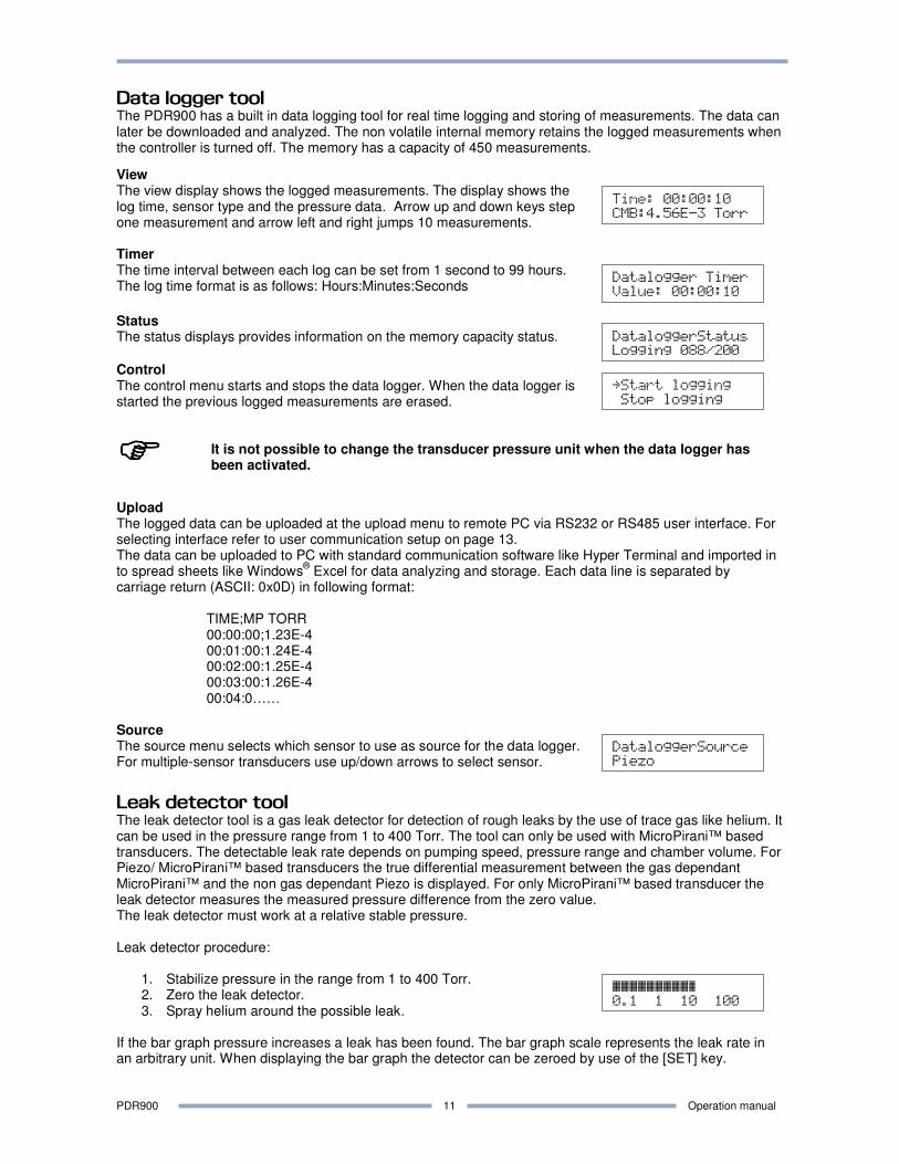
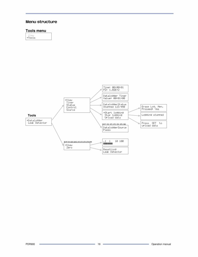
Data logger tool The PDR900 has a built in data logging tool for real time logging and storing of measurements. The data can later be downloaded and analyzed. The non volatile internal memory retains the logged measurements when the controller is turned off. The memory has a capacity of 450 measurements.
View The view display shows the logged measurements. The display shows the log time, sensor type and the pressure data. Arrow up and down keys step one measurement and arrow left and right jumps 10 measurements. Timer The time interval between each log can be set from 1 second to 99 hours. The log time format is as follows: Hours:Minutes:Seconds
Status The status displays provides information on the memory capacity status.
Control The control menu starts and stops the data logger. When the data logger is started the previous logged measurements are erased.
����
It is not possible to change the transducer pressure unit when the data logger has been activated.
Upload The logged data can be uploaded at the upload menu to remote PC via RS232 or RS485 user interface. For selecting interface refer to user communication setup on page 13. The data can be uploaded to PC with standard communication software like Hyper Terminal and imported in to spread sheets like Windows
® Excel for data analyzing and storage. Each data line is separated by
carriage return (ASCII: 0x0D) in following format:
TIME;MP TORR 00:00:00;1.23E-4 00:01:00:1.24E-4 00:02:00:1.25E-4 00:03:00:1.26E-4 00:04:0……
Source The source menu selects which sensor to use as source for the data logger. For multiple-sensor transducers use up/down arrows to select sensor.
Leak detector tool The leak detector tool is a gas leak detector for detection of rough leaks by the use of trace gas like helium. It can be used in the pressure range from 1 to 400 Torr. The tool can only be used with MicroPirani™ based transducers. The detectable leak rate depends on pumping speed, pressure range and chamber volume. For Piezo/ MicroPirani™ based transducers the true differential measurement between the gas dependant MicroPirani™ and the non gas dependant Piezo is displayed. For only MicroPirani™ based transducer the leak detector measures the measured pressure difference from the zero value. The leak detector must work at a relative stable pressure. Leak detector procedure:
1. Stabilize pressure in the range from 1 to 400 Torr. 2. Zero the leak detector. 3. Spray helium around the possible leak.
If the bar graph pressure increases a leak has been found. The bar graph scale represents the leak rate in an arbitrary unit. When displaying the bar graph the detector can be zeroed by use of the [SET] key.
PDR900 Operation manual
12
Enter pressure
4.00E-3 TORR
Enter pressure
5.00E-3 TORR
Direction 1
BELOW
Enable 1
ON
Enter pressure
+1.00E+3 Torr
Enter pressure
+9.00E-3 Torr
Action High
Loop
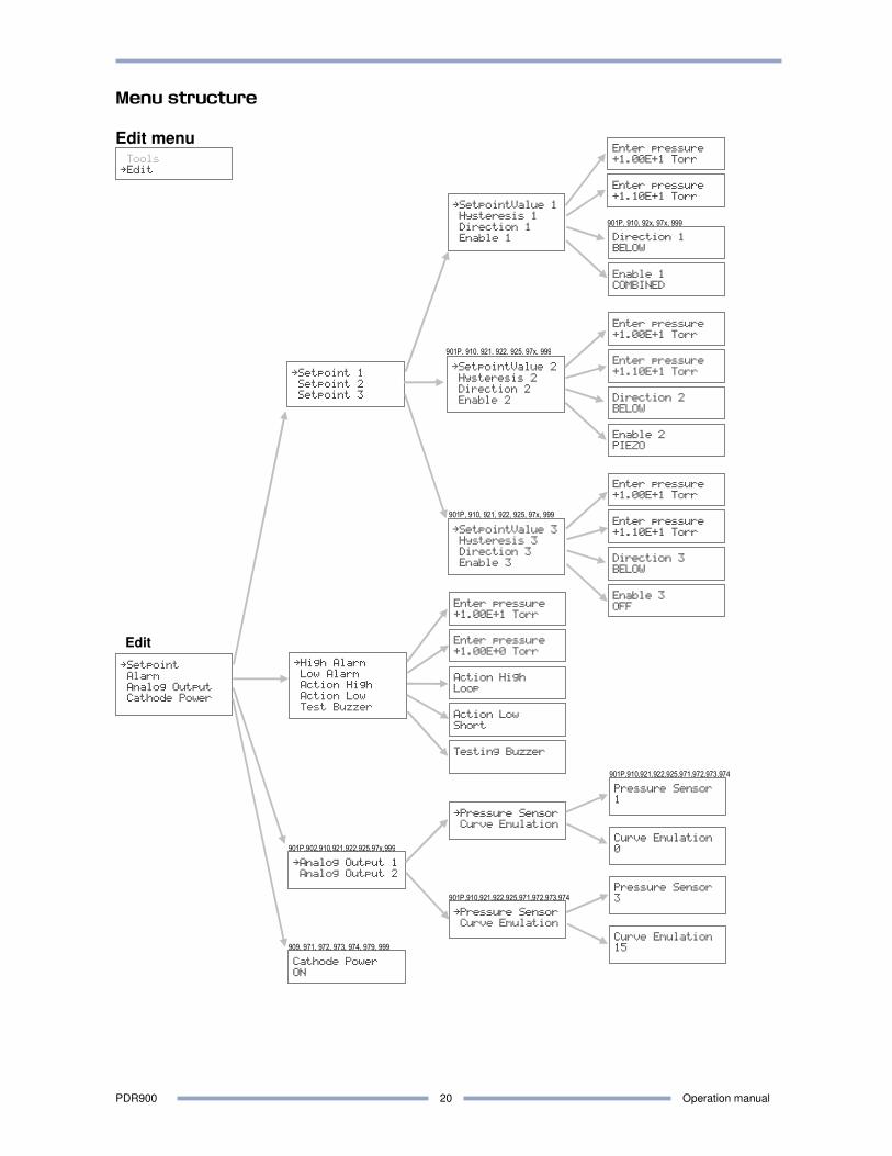
Edit menu
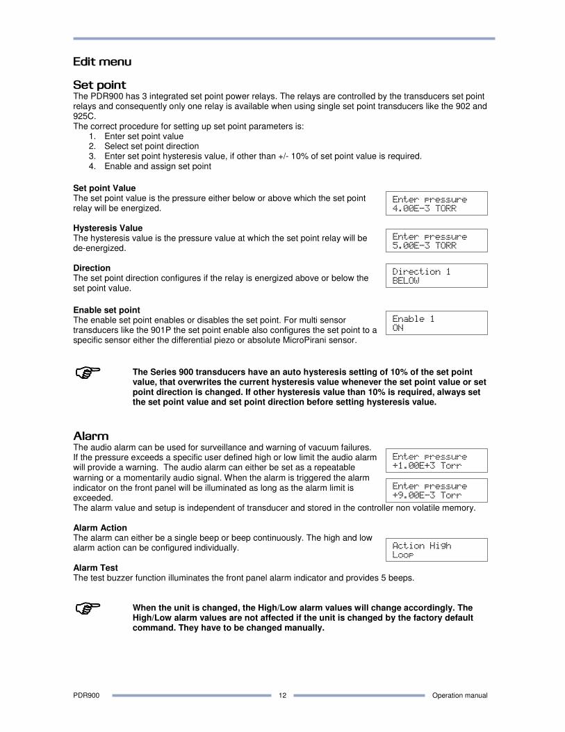
Set point The PDR900 has 3 integrated set point power relays. The relays are controlled by the transducers set point relays and consequently only one relay is available when using single set point transducers like the 902 and 925C. The correct procedure for setting up set point parameters is:
1. Enter set point value 2. Select set point direction 3. Enter set point hysteresis value, if other than +/- 10% of set point value is required. 4. Enable and assign set point
Set point Value The set point value is the pressure either below or above which the set point relay will be energized. Hysteresis Value The hysteresis value is the pressure value at which the set point relay will be de-energized. Direction The set point direction configures if the relay is energized above or below the set point value.
Enable set point The enable set point enables or disables the set point. For multi sensor transducers like the 901P the set point enable also configures the set point to a specific sensor either the differential piezo or absolute MicroPirani sensor.
����
The Series 900 transducers have an auto hysteresis setting of 10% of the set point value, that overwrites the current hysteresis value whenever the set point value or set point direction is changed. If other hysteresis value than 10% is required, always set the set point value and set point direction before setting hysteresis value.
Alarm The audio alarm can be used for surveillance and warning of vacuum failures. If the pressure exceeds a specific user defined high or low limit the audio alarm will provide a warning. The audio alarm can either be set as a repeatable
warning or a momentarily audio signal. When the alarm is triggered the alarm indicator on the front panel will be illuminated as long as the alarm limit is exceeded. The alarm value and setup is independent of transducer and stored in the controller non volatile memory. Alarm Action The alarm can either be a single beep or beep continuously. The high and low alarm action can be configured individually. Alarm Test The test buzzer function illuminates the front panel alarm indicator and provides 5 beeps.
����
When the unit is changed, the High/Low alarm values will change accordingly. The High/Low alarm values are not affected if the unit is changed by the factory default command. They have to be changed manually.
PDR900 Operation manual
13
Press SET when
pressure<5.00E-6
åLock Setup
Lock Controller
Display Sensor
Combined
Pressure Sensor
1
Curve Emulation
0
Cathode Power
ON
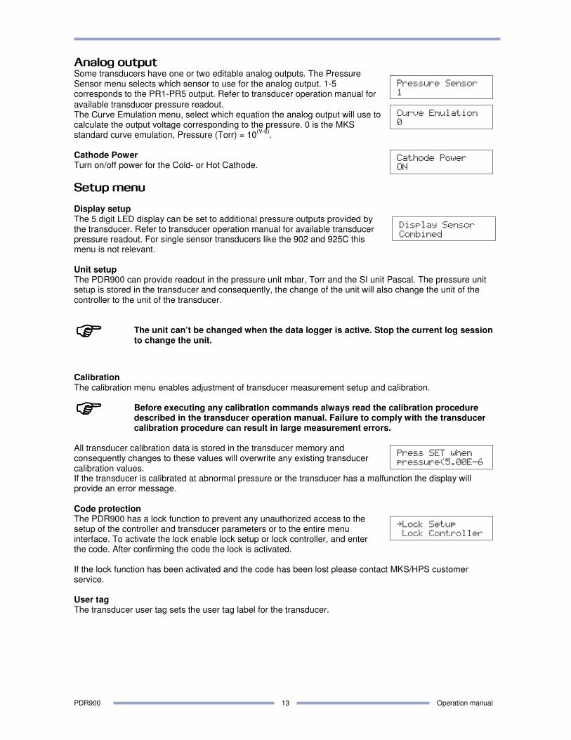
Analog output Some transducers have one or two editable analog outputs. The Pressure Sensor menu selects which sensor to use for the analog output. 1-5 corresponds to the PR1-PR5 output. Refer to transducer operation manual for
available transducer pressure readout. The Curve Emulation menu, select which equation the analog output will use to calculate the output voltage corresponding to the pressure. 0 is the MKS standard curve emulation, Pressure (Torr) = 10
(V-6).
Cathode Power Turn on/off power for the Cold- or Hot Cathode.
Setup menu Display setup The 5 digit LED display can be set to additional pressure outputs provided by the transducer. Refer to transducer operation manual for available transducer pressure readout. For single sensor transducers like the 902 and 925C this menu is not relevant. Unit setup The PDR900 can provide readout in the pressure unit mbar, Torr and the SI unit Pascal. The pressure unit setup is stored in the transducer and consequently, the change of the unit will also change the unit of the controller to the unit of the transducer.
����
The unit can’t be changed when the data logger is active. Stop the current log session to change the unit.
Calibration The calibration menu enables adjustment of transducer measurement setup and calibration.
����
Before executing any calibration commands always read the calibration procedure described in the transducer operation manual. Failure to comply with the transducer calibration procedure can result in large measurement errors.
All transducer calibration data is stored in the transducer memory and consequently changes to these values will overwrite any existing transducer calibration values. If the transducer is calibrated at abnormal pressure or the transducer has a malfunction the display will provide an error message. Code protection The PDR900 has a lock function to prevent any unauthorized access to the setup of the controller and transducer parameters or to the entire menu interface. To activate the lock enable lock setup or lock controller, and enter the code. After confirming the code the lock is activated. If the lock function has been activated and the code has been lost please contact MKS/HPS customer service. User tag The transducer user tag sets the user tag label for the transducer.
PDR900 Operation manual
14
åTransducer Adr.
Transducer Baud
Controller Adr.
Controller Baud
Interface
Test interface
Sending text:
PDR900 adr 253
Controller Comm.
RS232 interface
Controller Comm.
Address: 253
Factory default The factory default sets all parameter values for the controller or the transducer to the factory default settings. Refer to transducer operation manual for transducer factory default values: The factory default values for the controller are:
View Min.pressure 9.99E+09 Display setup PR1 View Max.pressure -9.99E+09 Unit setup Torr
Datalogger timer: 00:01:00 Controller user com adr. 253
Datalogger control Disabled Controller user com baud 9600
Datalogger source PR1 Controller user com interface RS232
Alarm high limit 1.00E+1 Lock Setup Disabled Alarm low limit 1.00E0 Lock Controller Disabled
Alarm high action OFF
Alarm low action OFF
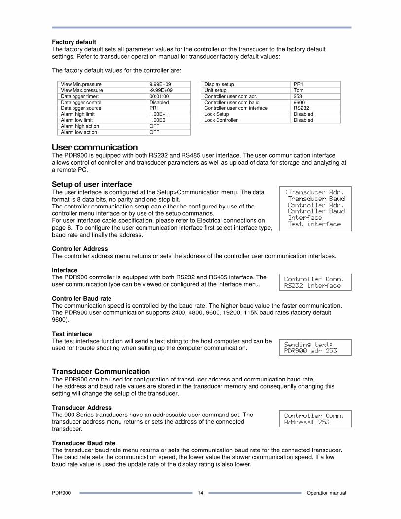
User communication The PDR900 is equipped with both RS232 and RS485 user interface. The user communication interface allows control of controller and transducer parameters as well as upload of data for storage and analyzing at a remote PC.
Setup of user interface The user interface is configured at the Setup>Communication menu. The data format is 8 data bits, no parity and one stop bit. The controller communication setup can either be configured by use of the controller menu interface or by use of the setup commands. For user interface cable specification, please refer to Electrical connections on page 6. To configure the user communication interface first select interface type, baud rate and finally the address. Controller Address The controller address menu returns or sets the address of the controller user communication interfaces. Interface The PDR900 controller is equipped with both RS232 and RS485 interface. The user communication type can be viewed or configured at the interface menu. Controller Baud rate The communication speed is controlled by the baud rate. The higher baud value the faster communication. The PDR900 user communication supports 2400, 4800, 9600, 19200, 115K baud rates (factory default 9600). Test interface The test interface function will send a text string to the host computer and can be used for trouble shooting when setting up the computer communication.
Transducer Communication The PDR900 can be used for configuration of transducer address and communication baud rate. The address and baud rate values are stored in the transducer memory and consequently changing this setting will change the setup of the transducer. Transducer Address The 900 Series transducers have an addressable user command set. The transducer address menu returns or sets the address of the connected transducer. Transducer Baud rate The transducer baud rate menu returns or sets the communication baud rate for the connected transducer. The baud rate sets the communication speed, the lower value the slower communication speed. If a low baud rate value is used the update rate of the display rating is also lower.
PDR900 Operation manual
15
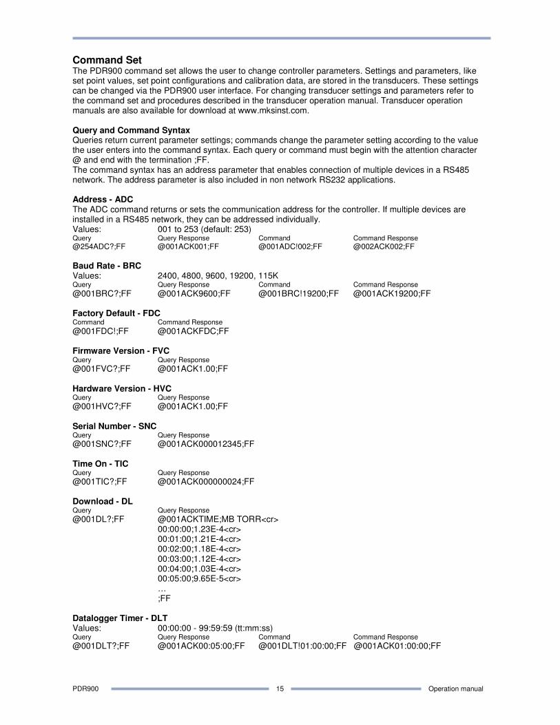
Command Set The PDR900 command set allows the user to change controller parameters. Settings and parameters, like set point values, set point configurations and calibration data, are stored in the transducers. These settings can be changed via the PDR900 user interface. For changing transducer settings and parameters refer to the command set and procedures described in the transducer operation manual. Transducer operation manuals are also available for download at www.mksinst.com. Query and Command Syntax Queries return current parameter settings; commands change the parameter setting according to the value the user enters into the command syntax. Each query or command must begin with the attention character @ and end with the termination ;FF. The command syntax has an address parameter that enables connection of multiple devices in a RS485 network. The address parameter is also included in non network RS232 applications. Address - ADC The ADC command returns or sets the communication address for the controller. If multiple devices are installed in a RS485 network, they can be addressed individually. Values: 001 to 253 (default: 253) Query Query Response Command Command Response
@254ADC?;FF @001ACK001;FF @001ADC!002;FF @002ACK002;FF
Baud Rate - BRC Values: 2400, 4800, 9600, 19200, 115K Query Query Response Command Command Response
@001BRC?;FF @001ACK9600;FF @001BRC!19200;FF @001ACK19200;FF Factory Default - FDC Command Command Response
@001FDC!;FF @001ACKFDC;FF Firmware Version - FVC Query Query Response @001FVC?;FF @001ACK1.00;FF Hardware Version - HVC Query Query Response @001HVC?;FF @001ACK1.00;FF Serial Number - SNC Query Query Response @001SNC?;FF @001ACK000012345;FF Time On - TIC Query Query Response @001TIC?;FF @001ACK000000024;FF Download - DL Query Query Response
@001DL?;FF @001ACKTIME;MB TORR<cr> 00:00:00;1.23E-4<cr> 00:01:00;1.21E-4<cr> 00:02:00;1.18E-4<cr> 00:03:00;1.12E-4<cr> 00:04:00;1.03E-4<cr> 00:05:00;9.65E-5<cr> … ;FF Datalogger Timer - DLT Values: 00:00:00 - 99:59:59 (tt:mm:ss) Query Query Response Command Command Response
@001DLT?;FF @001ACK00:05:00;FF @001DLT!01:00:00;FF @001ACK01:00:00;FF
PDR900 Operation manual
16
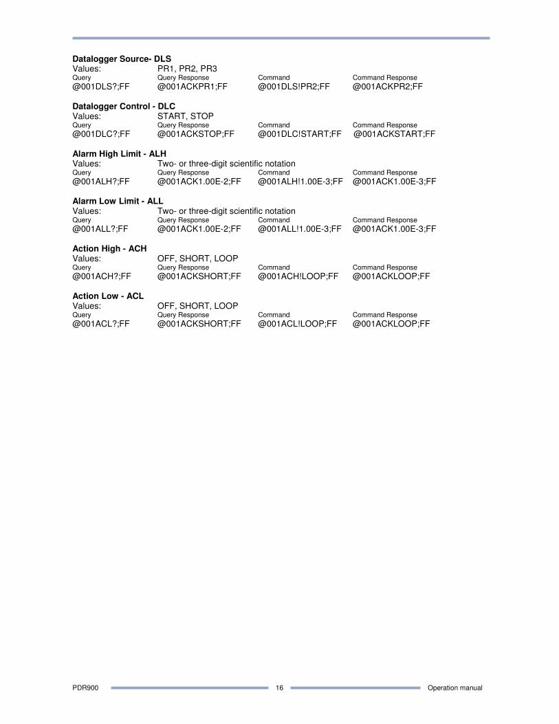
Datalogger Source- DLS Values: PR1, PR2, PR3 Query Query Response Command Command Response
@001DLS?;FF @001ACKPR1;FF @001DLS!PR2;FF @001ACKPR2;FF Datalogger Control - DLC Values: START, STOP Query Query Response Command Command Response
@001DLC?;FF @001ACKSTOP;FF @001DLC!START;FF @001ACKSTART;FF Alarm High Limit - ALH Values: Two- or three-digit scientific notation Query Query Response Command Command Response
@001ALH?;FF @001ACK1.00E-2;FF @001ALH!1.00E-3;FF @001ACK1.00E-3;FF Alarm Low Limit - ALL Values: Two- or three-digit scientific notation Query Query Response Command Command Response
@001ALL?;FF @001ACK1.00E-2;FF @001ALL!1.00E-3;FF @001ACK1.00E-3;FF Action High - ACH Values: OFF, SHORT, LOOP Query Query Response Command Command Response
@001ACH?;FF @001ACKSHORT;FF @001ACH!LOOP;FF @001ACKLOOP;FF Action Low - ACL Values: OFF, SHORT, LOOP Query Query Response Command Command Response
@001ACL?;FF @001ACKSHORT;FF @001ACL!LOOP;FF @001ACKLOOP;FF
PDR900 Operation manual
17
Searching for
transducer...
Zero adjustment
transd. error
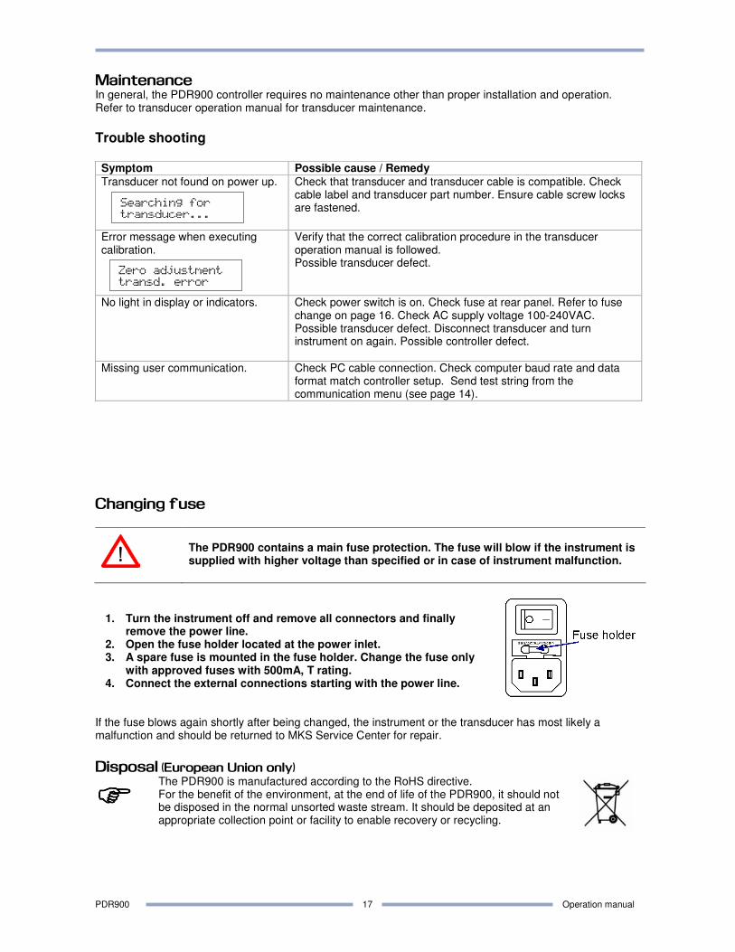
Maintenance In general, the PDR900 controller requires no maintenance other than proper installation and operation. Refer to transducer operation manual for transducer maintenance.
Trouble shooting Symptom Possible cause / Remedy
Transducer not found on power up.
Check that transducer and transducer cable is compatible. Check cable label and transducer part number. Ensure cable screw locks are fastened.
Error message when executing calibration.
Verify that the correct calibration procedure in the transducer operation manual is followed. Possible transducer defect.
No light in display or indicators. Check power switch is on. Check fuse at rear panel. Refer to fuse change on page 16. Check AC supply voltage 100-240VAC. Possible transducer defect. Disconnect transducer and turn instrument on again. Possible controller defect.
Missing user communication. Check PC cable connection. Check computer baud rate and data format match controller setup. Send test string from the communication menu (see page 14).
Changing fuse
The PDR900 contains a main fuse protection. The fuse will blow if the instrument is supplied with higher voltage than specified or in case of instrument malfunction.
1. Turn the instrument off and remove all connectors and finally remove the power line.
2. Open the fuse holder located at the power inlet. 3. A spare fuse is mounted in the fuse holder. Change the fuse only
with approved fuses with 500mA, T rating. 4. Connect the external connections starting with the power line.
If the fuse blows again shortly after being changed, the instrument or the transducer has most likely a malfunction and should be returned to MKS Service Center for repair.
Disposal (European Union only)
����
The PDR900 is manufactured according to the RoHS directive. For the benefit of the environment, at the end of life of the PDR900, it should not be disposed in the normal unsorted waste stream. It should be deposited at an appropriate collection point or facility to enable recovery or recycling.
PDR900 Operation manual
18
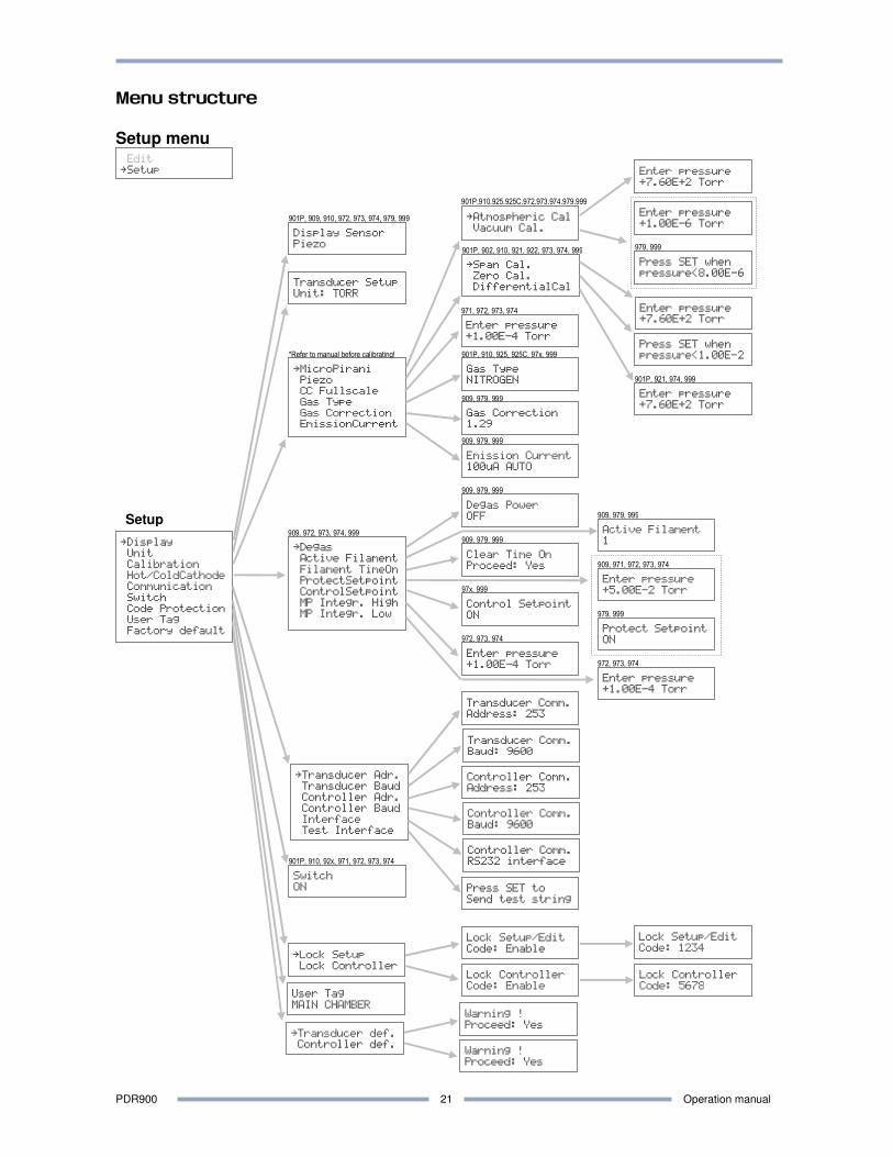
Menu structure
View menu
View
åGraph
PressureDisplay
Transducer
Setpoint Status
Controller
åView
Tools
ÆÆÆÆÆÆÆÆÆÆÆæ
-5-4-3-2-1 0+1+2
åMulti Reading
Min/Max Display
Reset Min/Max
åModel
Time On
Serial Number
Part Number
FirmwareVersion
HardwareVersion
Manufacturer
Temperature
Status
åSetpoint 1
Setpoint 2
Setpoint 3
åSerial Number
FirmwareVersion
HardwareVersion
Time On
Model: 901P
Loadlock Time On
1234 hours
Serial Number
0601109599
Firmware Version
2.00
Hardware Version
1.00
Manufacturer
MKS
Setpoint 1:Clear
Value: 1.23E-4
Setpoint 2:Set
Value: 4.23E-1
Setpoint 3:Set
Value: 9.88E-3
Serial Number
06123009876
Firmware Version
2.00
Hardware Version
1.00
Time On
5 hours
MP: 7.80E+2
PZ: 1.00E-1
CMB: 7.62E+2
CC: 0.00E+0
Resetting
Min/Max values
ÆÆÆÆÆÆ
-1000 -500 0
901P, 921, 974 (Differential output -)
901P, 910, 925, 925C
ÆÆÆÆÆæ
-1 0 +1 +2
902, 922
ÆÆÆÆÆÆÆÆæ
-9-8-7-6-5-4-3-2
909, 971
ÆÆÆÆÆÆÆÆÆÆÆÆæ
-9 -7 -5 -3 0+2
972, 973, 974, 979, 999
973, 974
999
MP: 7.80E+2
PZ: 1.00E-1
CMB: 7.62E+2
901P, 910
MP: 7.80E+2
CC: 1.00E-1
CMB: 7.62E+2
972
MP: 7.80E+2
HC: 0.00E+0
CMB: 7.62E+2
PZ: 7.62E+2
OK. No errors to
report
901P, 909, 910, 92x, 97x, 999
Model: 901P Loadlock 902 Piezo 909AR HCIG 910 DualTrans 921 Piezo Differential 922 Piezo Absolute 925 MicroPirani 971 UniMag 972 DualMag 973 TriMag 974 QuadMag 979 ATV Transducer 999 MP-HC 999
901P,902,910,92x,971,972,973,974
Filament Time On
F1 24 F2 0
909
Time On: 1172
F1 24 F2 0
979, 999
Max.Pr. 7.60E+2
Min.Pr. 1.11E-3
Part Number
901P-41050-0000
Temperature
25.0 deg. C
ÆÆÆÆÆÆÆÆÆÆæ
0 50 100
901P, 921, 974 (Differential output +)
979
MP: 7.80E+2
HC: 0.00E+0
CMB: 7.80E+2
901P,910,921,922,925,971,972,973,974
901P,902,909,910,92x,972,973,974,979,999
901P,902,909,910,921,922,925,97x,999 901P,909,910,921,922,925,97x,999
901P,909,910,921,922,925,97x,999
PDR900 Operation manual
19
Menu structure
Tools menu
Tools
åDatalogger
Leak Detector
åView
Timer
Status
Control
Source
åStart logging
Stop logging
Upload data
Erase Log. Mem.
Proceed: Yes
Press SET to’;
upload data
åView
Zero
DataloggerStatus
Stopped 123/450
Datalogger Timer
Value: 00:01:00
Time: 00:00:01
PZ: 1.02E+2
DataloggerSource
Piezo
.1 1 10 100
ÆÆÆÆÆÆæ
Resetting
Leak Detector
View
åTools
901P,910,925,925C,972,973,974,979,999
901P, 910, 972, 973, 974, 979, 999
Logging stopped
PDR900 Operation manual
20
Menu structure
Edit menu
Edit
åSetpoint
Alarm
Analog Output
Cathode Power
åSetpointValue 2
Hysteresis 2
Direction 2
Enable 2
åHigh Alarm
Low Alarm
Action High
Action Low
Test Buzzer
Enter pressure
+1.00E+1 Torr
Enter pressure
+1.00E+0 Torr
Action High
Loop
Testing Buzzer
åSetpoint 1
Setpoint 2
Setpoint 3
åSetpointValue 3
Hysteresis 3
Direction 3
Enable 3
åSetpointValue 1
Hysteresis 1
Direction 1
Enable 1
Action Low
Short
Enter pressure
+1.00E+1 Torr
Enter pressure
+1.10E+1 Torr
Direction 2
BELOW
Enable 2
PIEZO
Enter pressure
+1.00E+1 Torr
Enter pressure
+1.10E+1 Torr
Direction 1
BELOW
Enable 1
COMBINED
Enter pressure
+1.00E+1 Torr
Enter pressure
+1.10E+1 Torr
Direction 3
BELOW
Enable 3
OFF
Tools
åEdit
901P, 910, 921, 922, 925, 97x, 999
901P, 910, 921, 922, 925, 97x, 999
åAnalog Output 1
Analog Output 2
åPressure Sensor
Curve Emulation
åPressure Sensor
Curve Emulation
Pressure Sensor
1
Curve Emulation
0
Pressure Sensor
3
Curve Emulation
15
901P,902,910,921,922,925,97x,999
Cathode Power
ON
901P,910,921,922,925,971,972,973,974
909, 971, 972, 973, 974, 979, 999
901P, 910, 92x, 97x, 999
901P,910,921,922,925,971,972,973,974
PDR900 Operation manual
21
Menu structure
Setup menu
Setup
Edit
åSetup
åTransducer Adr.
Transducer Baud
Controller Adr.
Controller Baud
Interface
Test Interface
Transducer Setup
Unit: TORR
åLock Setup
Lock Controller
åMicroPirani
Piezo
CC Fullscale
Gas Type
Gas Correction
EmissionCurrent
åDisplay
Unit
Calibration
Hot/ColdCathode
Communication
Switch
Code Protection
User Tag
Factory default
Display Sensor
Piezo
User Tag
MAIN CHAMBER
åTransducer def.
Controller def.
Transducer Comm.
Address: 253
Transducer Comm.
Baud: 9600
Controller Comm.
Address: 253
Controller Comm.
Baud: 9600
Controller Comm.
RS232 interface
Gas Correction
1.29
Gas Type
NITROGEN
Lock Setup/Edit
Code: Enable
Lock Setup/Edit
Code: 1234
Lock Controller
Code: Enable
Lock Controller
Code: 5678
Warning !
Proceed: Yes
Warning !
Proceed: Yes
åDegas
Active Filament
Filament TimeOn
ProtectSetpoint
ControlSetpoint
MP Integr. High
MP Integr. Low
Control Setpoint
ON
Degas Power
OFF
Active Filament
1
Enter pressure
+5.00E-2 Torr
901P, 909, 910, 972, 973, 974, 979, 999 åAtmospheric Cal
Vacuum Cal.
åSpan Cal.
Zero Cal.
DifferentialCal
Press SET when
pressure<8.00E-6
Enter pressure
+7.60E+2 Torr
Press SET when
pressure<1.00E-2
Enter pressure
+7.60E+2 Torr
901P, 910, 925, 925C, 97x, 999
901P, 902, 910, 921, 922, 973, 974, 999
901P,910,925,925C,972,973,974,979,999
Emission Current
100uA AUTO
909, 979, 999
909, 979, 999
909, 972, 973, 974, 999
97x, 999
Enter pressure
+7.60E+2 Torr
901P, 921, 974, 999
Enter pressure
+1.00E-4 Torr
971, 972, 973, 974
909, 979, 999
909, 979, 999
909, 971, 972, 973, 974
Enter pressure
+1.00E-4 Torr
Switch
ON
*Refer to manual before calibrating!
Clear Time On
Proceed: Yes
909, 979, 999
972, 973, 974 Protect Setpoint
ON
979, 999
Enter pressure
+1.00E-6 Torr
979, 999
901P, 910, 92x, 971, 972, 973, 974
Enter pressure
+1.00E-4 Torr
972, 973, 974
Press SET to
Send test string
PDR900 Operation manual
22
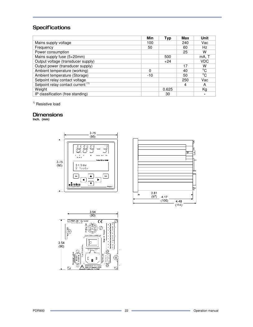
Specifications Min Typ Max Unit
Mains supply voltage 100 240 Vac
Frequency 50 60 Hz
Power consumption 25 W
Mains supply fuse (5×20mm) 500 mA, T
Output voltage (transducer supply) +24 VDC
Output power (transducer supply) 17 W
Ambient temperature (working) 0 40 oC
Ambient temperature (Storage) -10 50 oC
Setpoint relay contact voltage 250 Vac
Setpoint relay contact current (1)
4 A
Weight 0.625 Kg
IP classification (free standing) 30 -
1)
Resistive load
Dimensions Inch. (mm)
PDR900 Operation manual
23
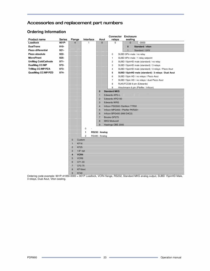
Accessories and replacement part numbers Ordering Information
Product name Series Flange Interface Aout Connector
relays Enclosure
sealing Loadlock 901P- 4 1 0 5 0 -0000
DualTrans 910- 0 Standard / viton
Piezo differential 921- 1 Standard / UHV
Piezo absolute 922- 0 SUBD 9Pin male / no relay
MicroPirani 925- 1 SUBD 9Pin male / 1 relay setpoint
UniMag ColdCathode 971- 2 SUBD 15pinHD male (standard) / no relay
DualMag CC/MP 972- 3 SUBD 15pinHD male (standard) / 3 relays
TriMag CC/MP/PZA 973- 4 SUBD 15pinHD male (standard) / 3 relays / Piezo Aout
QuadMag CC/MP/PZD 974- 5 SUBD 15pinHD male (standard) / 3 relays / Dual Aout
6 SUBD 15pin HD / no relays / Piezo Aout
7 SUBD 15pin HD / no relays / dual Piezo Aout
8 RJ45/FCC68 8 pin (Edwards)
9 Hirschmann 6 pin (Pfeiffer / Inficon)
0 Standard MKS
1 Edwards APG-L
2 Edwards APG100
3 Edwards WRG
4 Inficon PSG500 /Oerlikon TTR91
5 Inficon MPG400 / Pfeiffer PKR251
6 Inficon BPG400 (999 DAC2)
7 Brooks GP275
8 MKS Moducell
9 Hastings OBE 2000
0 -
1 RS232 / Analog
2 RS485 / Analog
0 Custom
1 KF16
2 KF25
3 1/8" npt
4 VCR4
5 VCR8
6 CF1.33
7 CF2.75
8 KF16ext
9 KF40
Ordering code example: 901P-41050-0000 = 901P Loadlock, VCR4 flange, RS232, Standard MKS analog output, SUBD 15pinHD Male, 3 relays, Dual Aout, Viton sealing.
PDR900 Operation manual
24
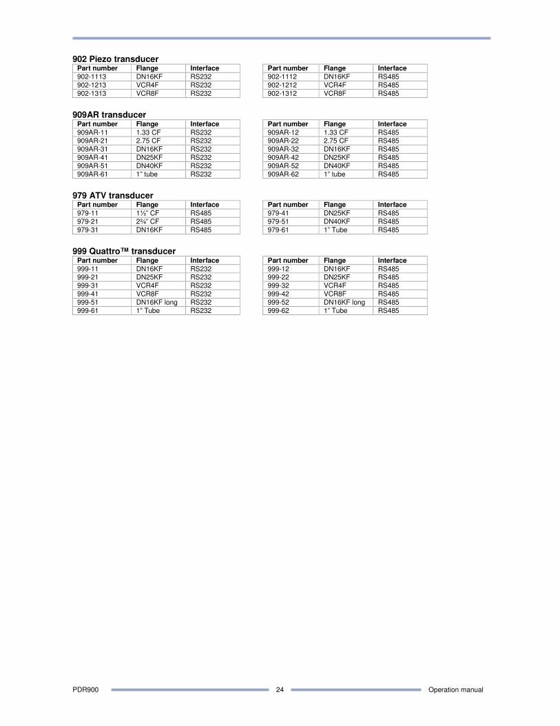
902 Piezo transducer Part number Flange Interface Part number Flange Interface
902-1113 DN16KF RS232 902-1112 DN16KF RS485
902-1213 VCR4F RS232 902-1212 VCR4F RS485
902-1313 VCR8F RS232 902-1312 VCR8F RS485
909AR transducer
Part number Flange Interface Part number Flange Interface
909AR-11 1.33 CF RS232 909AR-12 1.33 CF RS485 909AR-21 2.75 CF RS232 909AR-22 2.75 CF RS485
909AR-31 DN16KF RS232 909AR-32 DN16KF RS485
909AR-41 DN25KF RS232 909AR-42 DN25KF RS485
909AR-51 DN40KF RS232 909AR-52 DN40KF RS485
909AR-61 1” tube RS232 909AR-62 1” tube RS485
979 ATV transducer
Part number Flange Interface Part number Flange Interface
979-11 1⅓” CF RS485 979-41 DN25KF RS485 979-21 2¾” CF RS485 979-51 DN40KF RS485 979-31 DN16KF RS485 979-61 1” Tube RS485
999 Quattro™ transducer
Part number Flange Interface Part number Flange Interface
999-11 DN16KF RS232 999-12 DN16KF RS485 999-21 DN25KF RS232 999-22 DN25KF RS485
999-31 VCR4F RS232 999-32 VCR4F RS485
999-41 VCR8F RS232 999-42 VCR8F RS485
999-51 DN16KF long RS232 999-52 DN16KF long RS485
999-61 1” Tube RS232 999-62 1” Tube RS485
PDR900 Operation manual
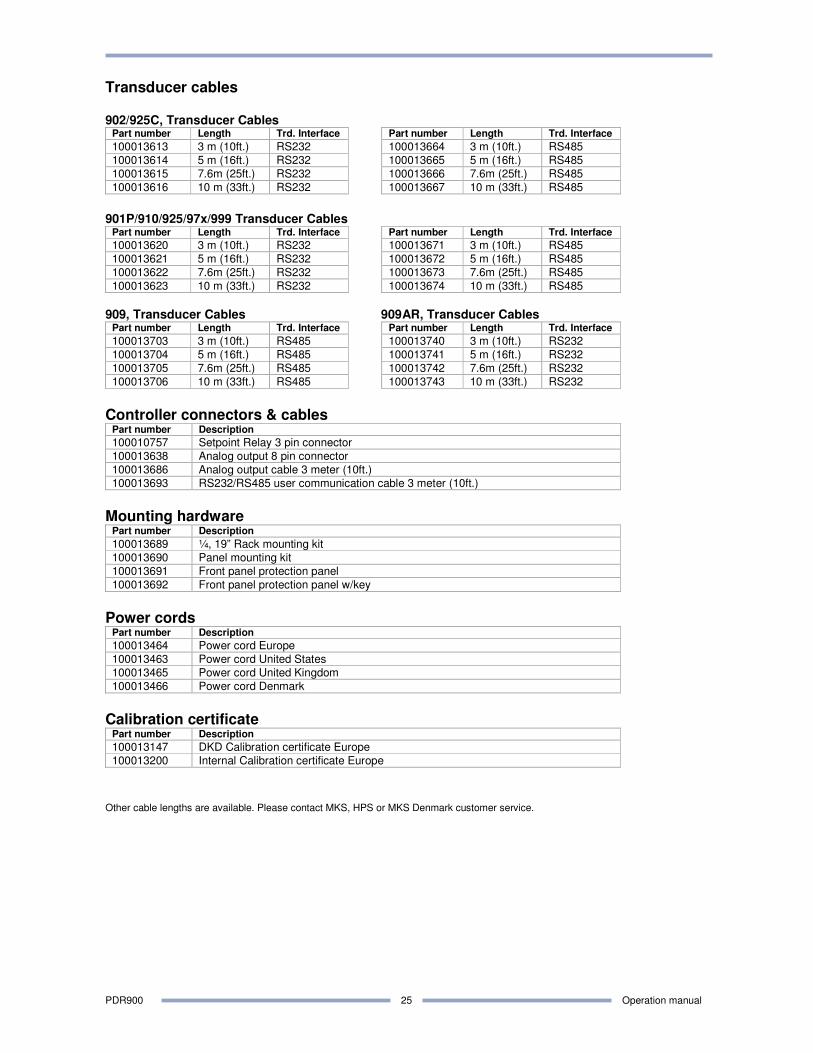
25
Transducer cables 902/925C, Transducer Cables
Part number Length Trd. Interface Part number Length Trd. Interface
100013613 3 m (10ft.) RS232 100013664 3 m (10ft.) RS485
100013614 5 m (16ft.) RS232 100013665 5 m (16ft.) RS485
100013615 7.6m (25ft.) RS232 100013666 7.6m (25ft.) RS485
100013616 10 m (33ft.) RS232 100013667 10 m (33ft.) RS485
901P/910/925/97x/999 Transducer Cables
Part number Length Trd. Interface Part number Length Trd. Interface
100013620 3 m (10ft.) RS232 100013671 3 m (10ft.) RS485
100013621 5 m (16ft.) RS232 100013672 5 m (16ft.) RS485
100013622 7.6m (25ft.) RS232 100013673 7.6m (25ft.) RS485
100013623 10 m (33ft.) RS232 100013674 10 m (33ft.) RS485
909, Transducer Cables 909AR, Transducer Cables
Part number Length Trd. Interface Part number Length Trd. Interface
100013703 3 m (10ft.) RS485 100013740 3 m (10ft.) RS232
100013704 5 m (16ft.) RS485 100013741 5 m (16ft.) RS232
100013705 7.6m (25ft.) RS485 100013742 7.6m (25ft.) RS232
100013706 10 m (33ft.) RS485 100013743 10 m (33ft.) RS232
Controller connectors & cables
Part number Description
100010757 Setpoint Relay 3 pin connector
100013638 Analog output 8 pin connector
100013686 Analog output cable 3 meter (10ft.)
100013693 RS232/RS485 user communication cable 3 meter (10ft.)
Mounting hardware
Part number Description
100013689 ¼, 19” Rack mounting kit
100013690 Panel mounting kit
100013691 Front panel protection panel
100013692 Front panel protection panel w/key
Power cords
Part number Description
100013464 Power cord Europe
100013463 Power cord United States
100013465 Power cord United Kingdom
100013466 Power cord Denmark
Calibration certificate
Part number Description
100013147 DKD Calibration certificate Europe
100013200 Internal Calibration certificate Europe
Other cable lengths are available. Please contact MKS, HPS or MKS Denmark customer service.
PDR900 Operation manual
26
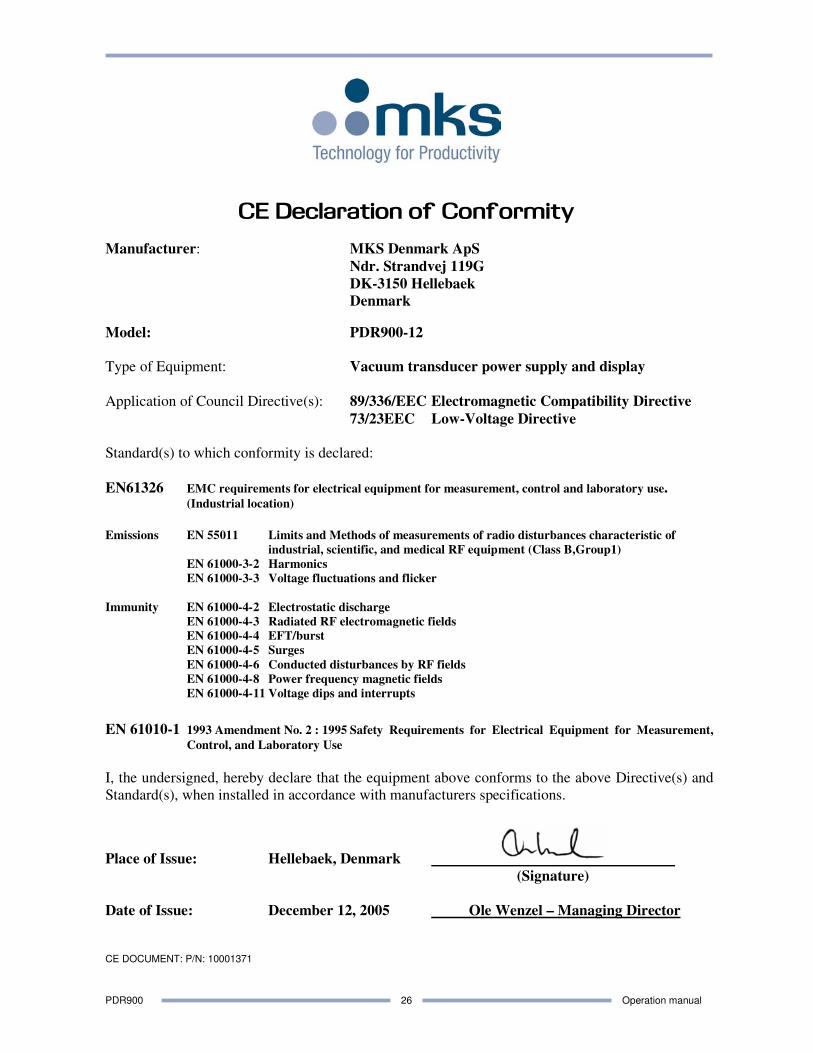
CE Declaration of Conformity
Manufacturer: MKS Denmark ApS
Ndr. Strandvej 119G
DK-3150 Hellebaek
Denmark
Model: PDR900-12
Type of Equipment: Vacuum transducer power supply and display
Application of Council Directive(s): 89/336/EEC Electromagnetic Compatibility Directive
73/23EEC Low-Voltage Directive
Standard(s) to which conformity is declared:
EN61326 EMC requirements for electrical equipment for measurement, control and laboratory use. (Industrial location)
Emissions EN 55011 Limits and Methods of measurements of radio disturbances characteristic of
industrial, scientific, and medical RF equipment (Class B,Group1)
EN 61000-3-2 Harmonics
EN 61000-3-3 Voltage fluctuations and flicker
Immunity EN 61000-4-2 Electrostatic discharge
EN 61000-4-3 Radiated RF electromagnetic fields
EN 61000-4-4 EFT/burst
EN 61000-4-5 Surges
EN 61000-4-6 Conducted disturbances by RF fields
EN 61000-4-8 Power frequency magnetic fields
EN 61000-4-11 Voltage dips and interrupts
EN 61010-1 1993 Amendment No. 2 : 1995 Safety Requirements for Electrical Equipment for Measurement,
Control, and Laboratory Use
I, the undersigned, hereby declare that the equipment above conforms to the above Directive(s) and
Standard(s), when installed in accordance with manufacturers specifications.
Place of Issue: Hellebaek, Denmark
(Signature)
Date of Issue: December 12, 2005 Ole Wenzel – Managing Director
CE DOCUMENT: P/N: 10001371

PDR900 Operation manual
27
Notes
PDR900 Operation manual
28
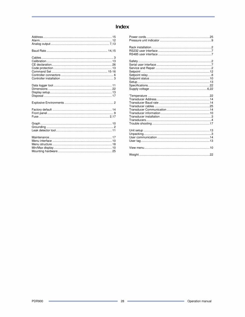
Index
Address................................................................................ 15 Alarm.................................................................................... 12 Analog output .................................................................... 7,13 Baud Rate ....................................................................... 14,15 Cables.................................................................................... 3 Calibration............................................................................ 13 CE declaration...................................................................... 26 Code protection.................................................................... 13 Command Set ................................................................. 15-16 Controller connectors ............................................................. 6 Controller installation.............................................................. 3 Data logger tool .................................................................... 11 Dimensions .......................................................................... 22 Display setup........................................................................ 13 Disposal ............................................................................... 17 Explosive Environments ......................................................... 2 Factory default ..................................................................... 14 Front panel ............................................................................. 9 Fuse.................................................................................. 2,17 Graph................................................................................... 10 Grounding .............................................................................. 2 Leak detector tool................................................................. 11 Maintenance......................................................................... 17 Menu interface ..................................................................... 10 Menu structure ..................................................................... 18 Min/Max display.................................................................... 10 Mounting hardware............................................................... 25
Power cords..........................................................................25 Pressure unit indicator ............................................................9 Rack installation......................................................................2 RS232 user interface ..............................................................7 RS485 user interface ..............................................................7 Safety .....................................................................................2 Serial user interface................................................................7 Service and Repair .................................................................2 Setpoint ................................................................................12 Setpoint relay..........................................................................8 Setpoint status ......................................................................10 Setup ....................................................................................13 Specifications........................................................................22 Supply voltage ...................................................................6,22 'Temperature ........................................................................22 Transducer Address..............................................................14 Transducer Baud rate ...........................................................14 Transducer cables ................................................................25 Transducer Communication ..................................................14 Transducer information .........................................................10 Transducer installation............................................................3 Transducers............................................................................4 Trouble shooting ...................................................................17 Unit setup .............................................................................13 Unpacking...............................................................................3 User communication .............................................................14 User tag................................................................................13 View menu............................................................................10 Weight ..................................................................................22

P/N: 100017303 PDR900-12, Operation Manual Revision: A, November 2008