Embed Size (px)
Citation preview
SYSTEMS SIMULATION
SOFTWARE PROCESS FLOW & HEAT
TRANSFER
Company Overview (M-Tech Industrial) – ISO9001 accredited multi-disciplinary engineering company
headquartered in South Africa
– 20 full-time support personnel and a core group of 35 engineering consultants, programmers and technicians.
– Founded 1987
– Annual Turnover R 350m
Products – Flownex Simulation Environment
– Enerflow Heat Pumps for industrial, commercial and residential applications.
Services – Specialised Consultation and Owners Engineering
– Demand Side Management and Energy Efficiency
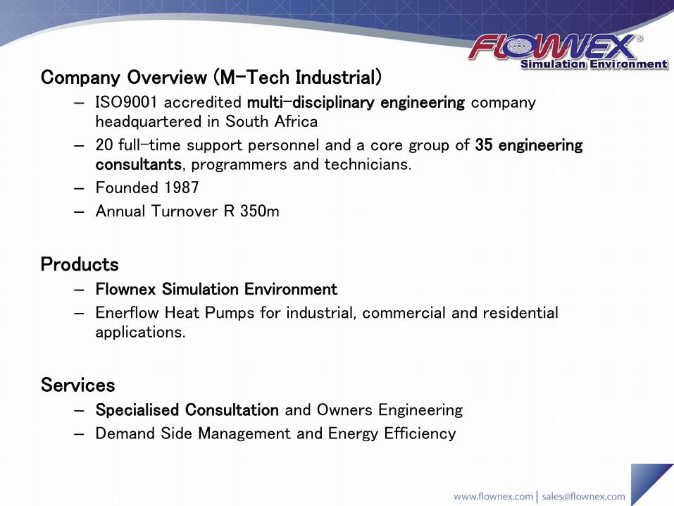
SYSTEMS SIMULATION
SOFTWARE PROCESS FLOW & HEAT
TRANSFER
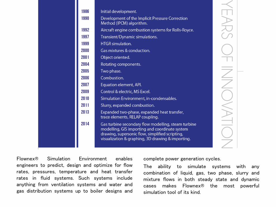
Flownex® Simulation Environment enables engineers to predict, design and optimize for flow rates, pressures, temperature and heat transfer rates in fluid systems. Such systems include anything from ventilation systems and water and gas distribution systems up to boiler designs and
complete power generation cycles.
The ability to simulate systems with any combination of liquid, gas, two phase, slurry and mixture flows in both steady state and dynamic cases makes Flownex® the most powerful simulation tool of its kind.
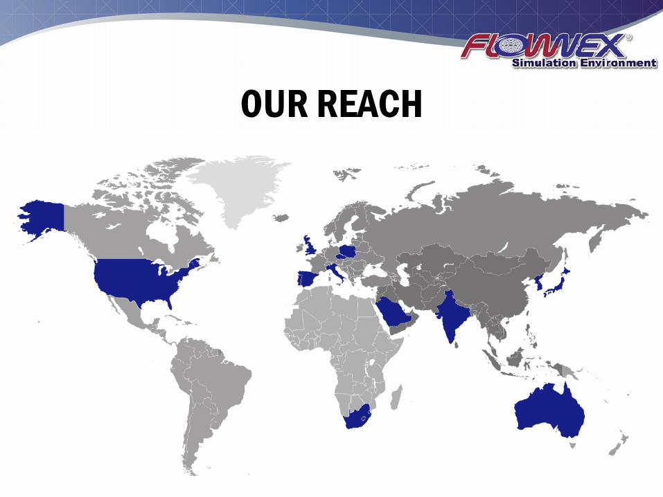
OUR REACH
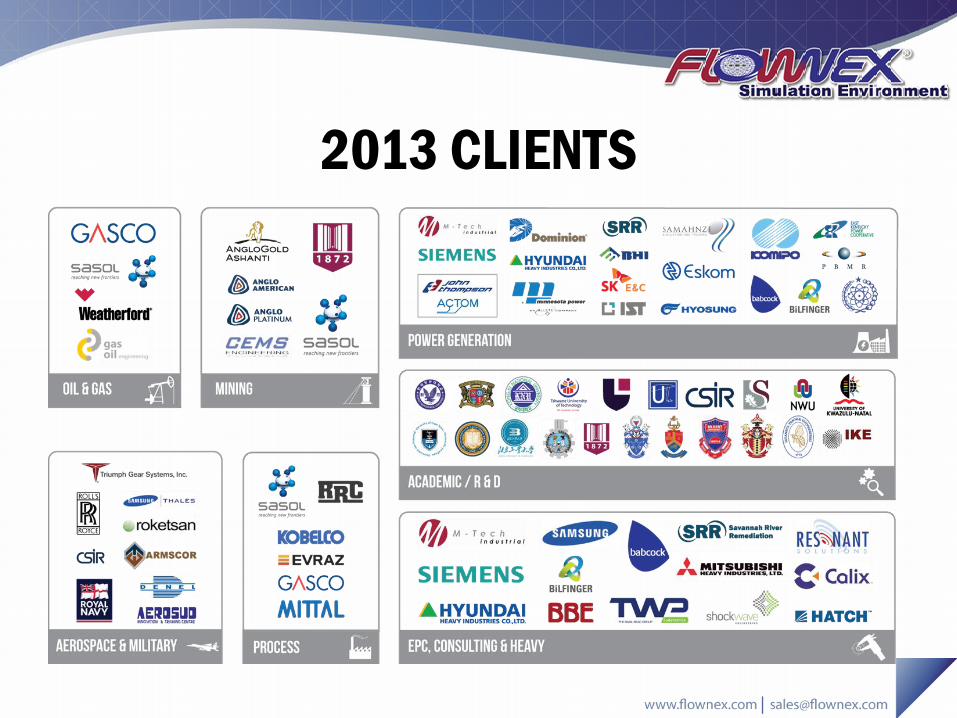
2013 CLIENTS
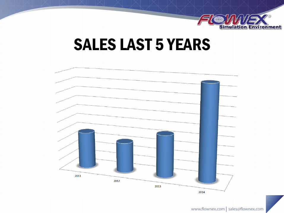
SALES LAST 5 YEARS
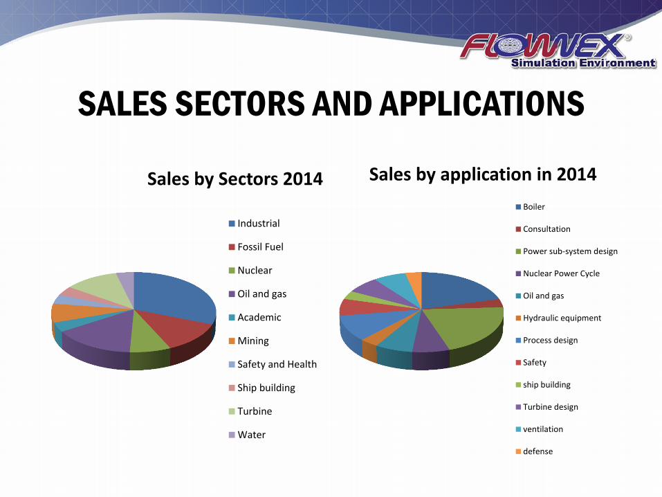
SALES SECTORS AND APPLICATIONS
Sales by Sectors 2014
Industrial
Fossil Fuel
Nuclear
Oil and gas
Academic
Mining
Safety and Health
Ship building
Turbine
Water
Sales by application in 2014
Boiler
Consultation
Power sub-system design
Nuclear Power Cycle
Oil and gas
Hydraulic equipment
Process design
Safety
ship building
Turbine design
ventilation
defense
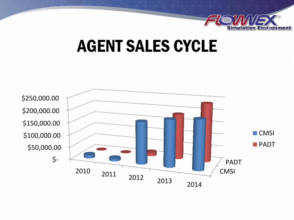
AGENT SALES CYCLE
CMSIPADT $-
$50,000.00
$100,000.00
$150,000.00
$200,000.00
$250,000.00
2010 2011 2012 2013 2014
CMSI
PADT
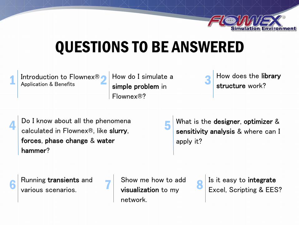
QUESTIONS TO BE ANSWERED
Introduction to Flownex® Application & Benefits
How does the library
structure work?
Running transients and
various scenarios.
Show me how to add
visualization to my
network.
What is the designer, optimizer &
sensitivity analysis & where can I
apply it?
Is it easy to integrate
Excel, Scripting & EES?
Do I know about all the phenomena
calculated in Flownex®, like slurry,
forces, phase change & water
hammer?
1 3 How do I simulate a
simple problem in
Flownex®?
2
4 5
6 7 8
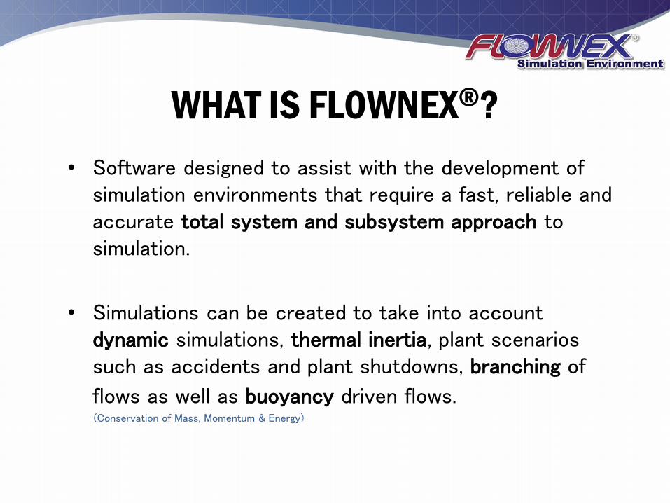
WHAT IS FLOWNEX®?
• Software designed to assist with the development of simulation environments that require a fast, reliable and accurate total system and subsystem approach to simulation.
• Simulations can be created to take into account dynamic simulations, thermal inertia, plant scenarios such as accidents and plant shutdowns, branching of
flows as well as buoyancy driven flows. (Conservation of Mass, Momentum & Energy)
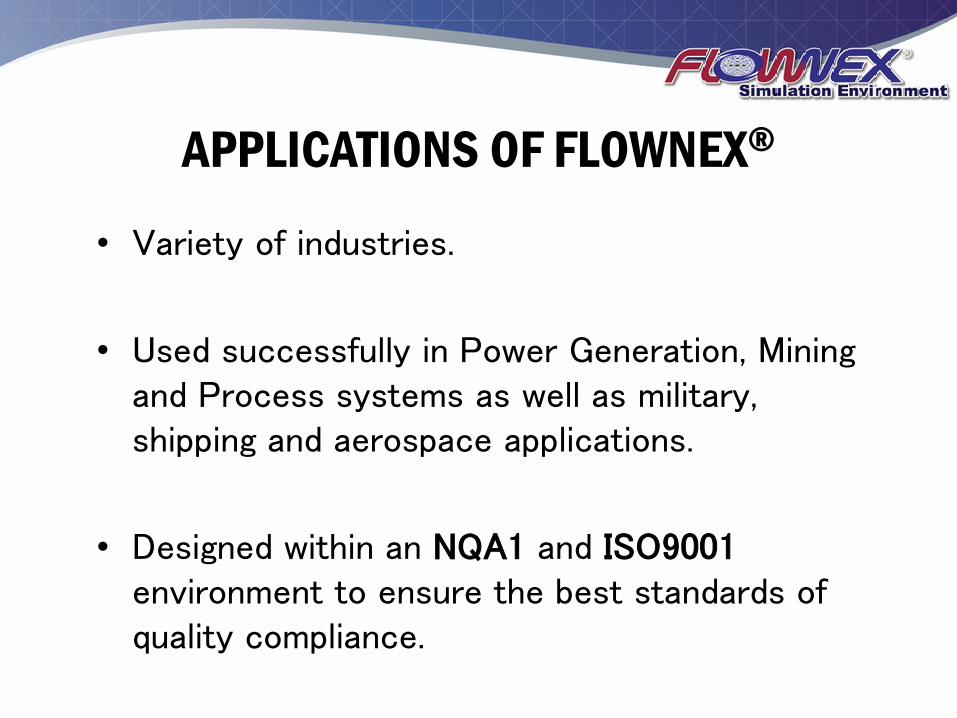
APPLICATIONS OF FLOWNEX®
• Variety of industries.
• Used successfully in Power Generation, Mining and Process systems as well as military, shipping and aerospace applications.
• Designed within an NQA1 and ISO9001 environment to ensure the best standards of quality compliance.
BENEFITS OF FLOWNEX®
• Enables engineers to predict, design and optimize for flow rates, pressures, temperatures and heat transfer rates in fluid systems.
• Includes anything from ventilation systems and water and gas distribution systems, up to boiler designs and complete power generation cycles.
BENEFITS OF FLOWNEX®
• The ability to simulate systems with any combination of liquid, gas, two phase, slurry and mixture flows in both steady state and dynamic cases makes Flownex® the most powerful simulation tool of its kind.
FUNDAMENTALS OF THE
FLOWNEX® SOLVER
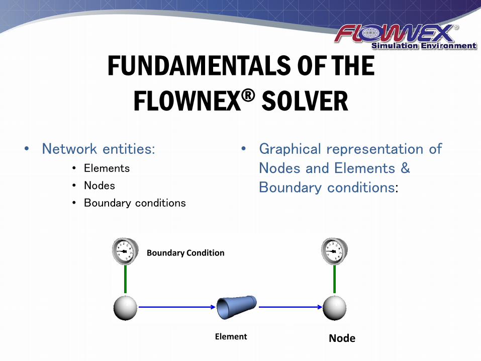
• Network entities: • Elements
• Nodes
• Boundary conditions
• Graphical representation of Nodes and Elements & Boundary conditions:
Boundary Condition
Element Node

FLOWNEX® SE LIBRARIES
Flownex® contains a large and extendable library of components to allow users to quickly setup and model flow systems.
FLOWNEX®
COMPLEMENTING SOFTWARE
FLOWNEX ®
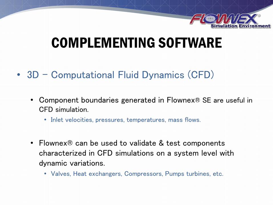
• 3D - Computational Fluid Dynamics (CFD)
• Component boundaries generated in Flownex® SE are useful in CFD simulation.
• Inlet velocities, pressures, temperatures, mass flows.
• Flownex® can be used to validate & test components characterized in CFD simulations on a system level with dynamic variations. • Valves, Heat exchangers, Compressors, Pumps turbines, etc.
COMPLEMENTING SOFTWARE
FLOWNEX ®
• Pipe Stress Analysis • Flownex® calculates forces & loads on pipes and bends due
to changes in pressure and velocity which can be used as inputs to pipe stress analysis software.
• Control • With the ability to simulate systems dynamically Flownex®
can be used to validate, develop and optimize control systems.
FLOWNEX® RELEASE 2014
Flownex® Simulation Environment RELEASE FEATURES & CAPABILITIES
“It is unbelievable what we have achieved in the last 12 months; our approach of working closely with our clients and industry professionals
to enhance Flownex ®’s capabilities has once again proven itself and allowed us to deliver a product that is well aligned to the ground-
breaking advances our users are achieving”
Tiaan Dercksen – Principal, Software Development
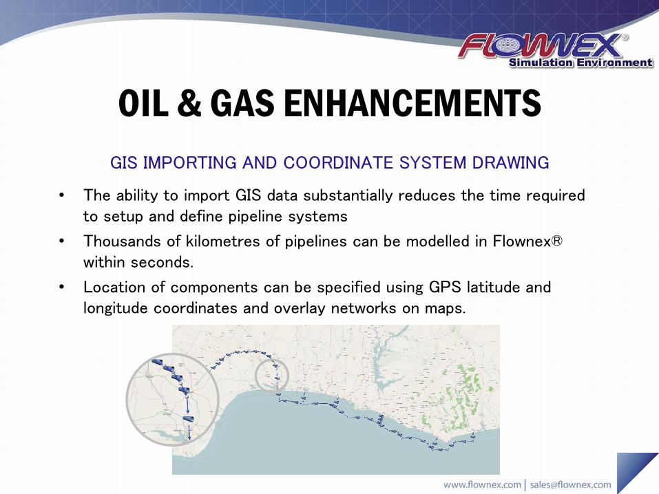
OIL & GAS ENHANCEMENTS
• The ability to import GIS data substantially reduces the time required to setup and define pipeline systems
• Thousands of kilometres of pipelines can be modelled in Flownex® within seconds.
• Location of components can be specified using GPS latitude and longitude coordinates and overlay networks on maps.
GIS IMPORTING AND COORDINATE SYSTEM DRAWING

TURBO MACHINERY ENHANCEMENTS
• Enables users to apply the unparalleled stability, solution speed and accuracy to detailed modelling of secondary flow in gas turbines.
• Key features:
– Swirl solver,
– Rotating cavities,
– Vortices,
– Seals
– Rotating channel modelling.
SECONDARY FLOW ANALYSIS & STEAM TURBINE MODELLING
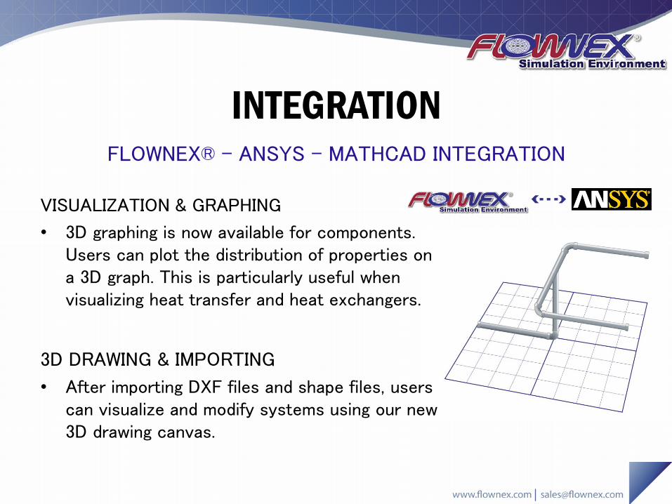
INTEGRATION FLOWNEX® - ANSYS - MATHCAD INTEGRATION
VISUALIZATION & GRAPHING
• 3D graphing is now available for components. Users can plot the distribution of properties on a 3D graph. This is particularly useful when visualizing heat transfer and heat exchangers.
3D DRAWING & IMPORTING
• After importing DXF files and shape files, users can visualize and modify systems using our new 3D drawing canvas.
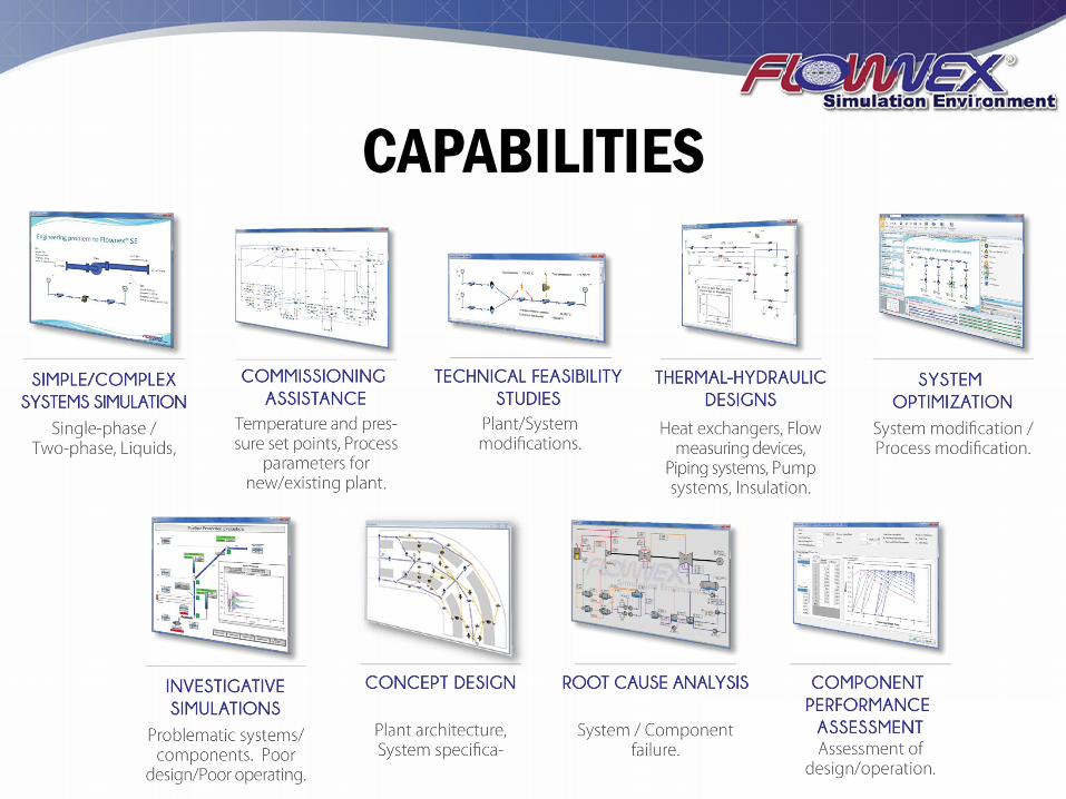
CAPABILITIES
FLOWNEX ®
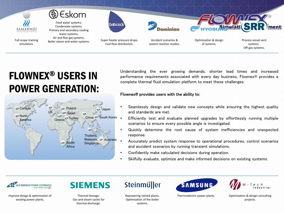
Understanding the ever growing demands, shorter lead times and increased performance requirements associated with every day business, Flownex® provides a complete thermal fluid simulation platform to meet these challenges.
Flownex® provides users with the ability to:
• Seamlessly design and validate new concepts while ensuring the highest quality and standards are met.
• Efficiently test and evaluate planned upgrades by effortlessly running multiple scenarios to ensure every possible angle is investigated.
• Quickly determine the root cause of system inefficiencies and unexpected response.
• Accurately predict system response to operational procedures, control scenarios and accident scenarios by running transient simulations.
• Confidently make calculated decisions during operation.
• Skilfully evaluate, optimize and make informed decisions on existing systems.
Canada
North
America
South
Africa
China South Korea
Japan
Australia
Thailand,
Malaysia,
Singapore
Greece Turkey
Israel
Poland
UK
Repowering retired plants. Optimization of the boiler
systems.
Super heater pressure drops. Fuel flow distribution.
Feed water systems. Condensate systems.
Primary and secondary cooling water systems.
Air and flue gas systems. Boiler steam and water systems. Full scope training
simulators. Process vessel vent
systems. Off-gas systems.
Accident scenarios & system reaction studies.
Thermal Storage. Gas and steam cycles for
thermal discharge.
Improve design & optimization of existing power plants.
Thermoelectric power plants. Optimization & design consulting projects.
Optimisation & design of systems.
FLOWNEX® USERS IN
POWER GENERATION:
FLOWNEX ®
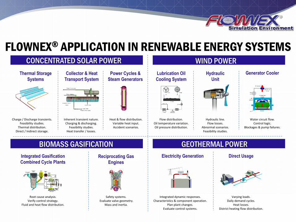
FLOWNEX® APPLICATION IN RENEWABLE ENERGY SYSTEMS CONCENTRATED SOLAR POWER WIND POWER
BIOMASS GASIFICATION GEOTHERMAL POWER
Generator Cooler Thermal Storage
Systems
Power Cycles &
Steam Generators
Collector & Heat
Transport System
Hydraulic
Unit
Lubrication Oil
Cooling System
Charge / Discharge transients. Feasibility studies.
Thermal distribution. Direct / Indirect storage.
Inherent transient nature. Charging & discharging.
Feasibility studies. Heat transfer / losses.
Heat & flow distribution. Variable heat input. Accident scenarios.
Flow distribution. Oil temperature variation. Oil pressure distribution.
Hydraulic line. Flow losses.
Abnormal scenarios. Feasibility studies.
Water circuit flow. Control logic.
Blockages & pump failures.
Integrated Gasification
Combined Cycle Plants
Direct Usage Reciprocating Gas
Engines
Electricity Generation
Integrated dynamic responses. Characteristics & component operation.
Plan plant changes. Evaluate control systems.
Varying loads. Daily demand cycles.
Heat losses. District heating flow distribution.
Safety systems. Evaluate valve geometry.
Mass and inertia.
Root cause analysis. Verify control strategy.
Fluid and heat flow distribution.
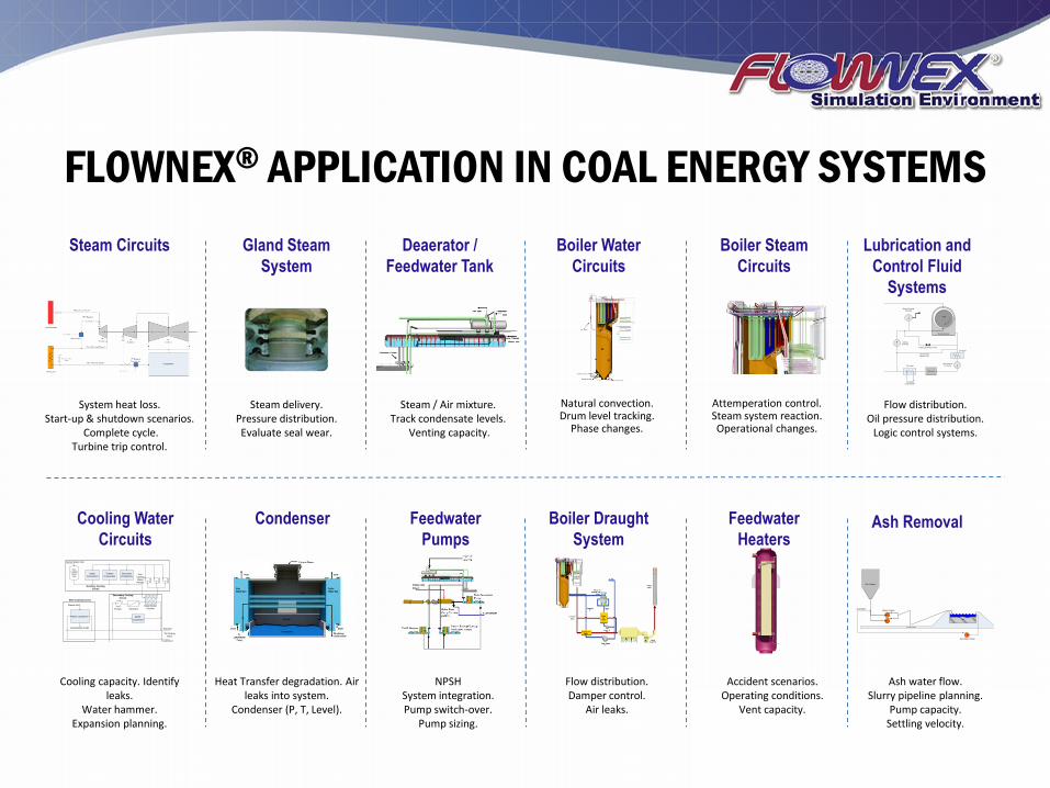
FLOWNEX® APPLICATION IN COAL ENERGY SYSTEMS
Bearing Casing
Shaft
Manual Jacking
Oil Pump
Jacking Oil Relieve Valve
Jacking
Oil Pump
Low Pressure
Oil Pump
Filter Unit
Oil Cooler
Oil Heater
Low Pressure
Bypass Line
Circulating
Cooling Water
Lubrication and
Control Fluid
Systems
Deaerator /
Feedwater Tank
Boiler Water
Circuits
Steam Circuits Boiler Steam
Circuits
Gland Steam
System
Natural convection. Drum level tracking.
Phase changes.
Flow distribution. Oil pressure distribution.
Logic control systems.
Steam delivery. Pressure distribution. Evaluate seal wear.
Steam / Air mixture. Track condensate levels.
Venting capacity.
System heat loss. Start-up & shutdown scenarios.
Complete cycle. Turbine trip control.
Attemperation control. Steam system reaction. Operational changes.
Boiler Draught
System
Condenser Ash Removal Cooling Water
Circuits
Slurry Pumps
Ash Hopper
Ash Water Pump
Ash Water
Ground Level
Ash
WaterMain Condenser
Hot Duct
Cold Duct
Condensate Outlet
Steam Inlet
Main Cooling Circuit
BFPT
Condenser
Water/Water
Coolers
Secondary Cooling
Circuit
Generator
Consumers
Turbine
ConsumersOther
Consumers
Demin Water Inlet
Aux.
Cooling
Water
Pumps
Aux.
Cooling
Water
Tank
Auxiliary Cooling
Circuit
To Cooling
Tower
StrainersPumps
Feedwater
Pumps
Feedwater
Heaters
Ash water flow. Slurry pipeline planning.
Pump capacity. Settling velocity.
Accident scenarios. Operating conditions.
Vent capacity.
Flow distribution. Damper control.
Air leaks.
NPSH System integration. Pump switch-over.
Pump sizing.
Heat Transfer degradation. Air leaks into system.
Condenser (P, T, Level).
Cooling capacity. Identify leaks.
Water hammer. Expansion planning.

FLOWNEX® APPLICATION IN MINING CHILLED WATER RETICULATION VENTILATION
Heat Loads Chiller Plants Spot Coolers Chilled Water
Transport Ventilation
System Ventilation System
Control
Compression cycles. Cooling towers. Bulk air coolers.
Water circulation networks.
Pumps. Turbines.
Spot coolers. Water storage dams. Mining machinery.
Vapour compression cycles. Compressor. Condenser.
Expansion valve. Evaporator.
Bulkheads. Ventilation doors.
Regulators.
Booster, aux and main fans. Heat exchangers.
Air coolers. Main & ventilation shaft.
Underground tunnel network.
Auto-compression. Heat flow from surrounding
rock. Heat flow from fissure
water.
SLURRY COMPRESSED AIR
Compressor lines. Air Distribution networks. Pneumatic Machinery.
Backfill transport in deep mines. Hydraulic materials transport. Hydraulic transport of fine ore. Transport of processed ore to tailings dams.
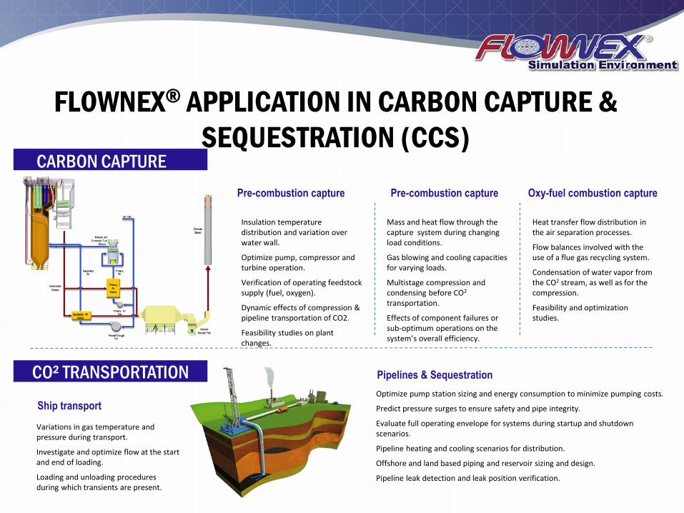
FLOWNEX® APPLICATION IN CARBON CAPTURE &
SEQUESTRATION (CCS) CARBON CAPTURE
Pre-combustion capture
CO² TRANSPORTATION
Pre-combustion capture Oxy-fuel combustion capture
Mass and heat flow through the capture system during changing load conditions.
Gas blowing and cooling capacities for varying loads.
Multistage compression and condensing before CO2 transportation.
Effects of component failures or sub-optimum operations on the system’s overall efficiency.
Insulation temperature distribution and variation over water wall.
Optimize pump, compressor and turbine operation.
Verification of operating feedstock supply (fuel, oxygen).
Dynamic effects of compression & pipeline transportation of CO2.
Feasibility studies on plant changes.
Heat transfer flow distribution in the air separation processes.
Flow balances involved with the use of a flue gas recycling system.
Condensation of water vapor from the CO2 stream, as well as for the compression.
Feasibility and optimization studies.
Ship transport
Pipelines & Sequestration
Variations in gas temperature and pressure during transport.
Investigate and optimize flow at the start and end of loading.
Loading and unloading procedures during which transients are present.
Optimize pump station sizing and energy consumption to minimize pumping costs.
Predict pressure surges to ensure safety and pipe integrity.
Evaluate full operating envelope for systems during startup and shutdown scenarios.
Pipeline heating and cooling scenarios for distribution.
Offshore and land based piping and reservoir sizing and design.
Pipeline leak detection and leak position verification.
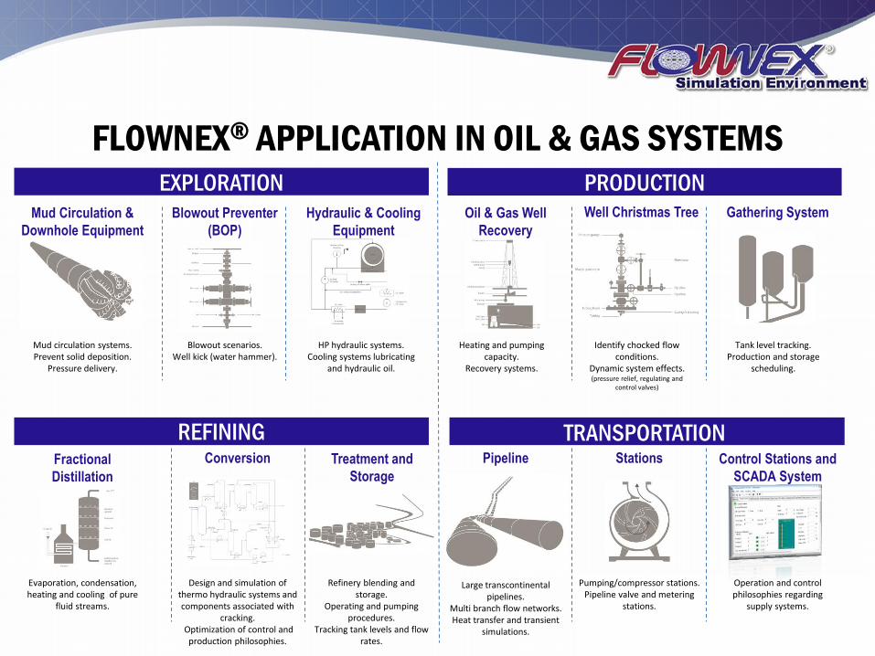
Mud circulation systems. Prevent solid deposition.
Pressure delivery.
Blowout scenarios. Well kick (water hammer).
HP hydraulic systems. Cooling systems lubricating
and hydraulic oil.
Heating and pumping capacity.
Recovery systems.
Identify chocked flow conditions.
Dynamic system effects. (pressure relief, regulating and
control valves)
Tank level tracking. Production and storage
scheduling.
FLOWNEX® APPLICATION IN OIL & GAS SYSTEMS EXPLORATION PRODUCTION
TRANSPORTATION
Gathering System
Fractional
Distillation
Mud Circulation &
Downhole Equipment
Pipeline
Hydraulic & Cooling
Equipment
Blowout Preventer
(BOP)
Conversion
Well Christmas Tree Oil & Gas Well
Recovery
Control Stations and
SCADA System
Treatment and
Storage
Stations
Evaporation, condensation, heating and cooling of pure
fluid streams.
Design and simulation of thermo hydraulic systems and components associated with
cracking. Optimization of control and
production philosophies.
Refinery blending and storage.
Operating and pumping procedures.
Tracking tank levels and flow rates.
Large transcontinental pipelines.
Multi branch flow networks. Heat transfer and transient
simulations.
Pumping/compressor stations. Pipeline valve and metering
stations.
Operation and control philosophies regarding
supply systems.
REFINING
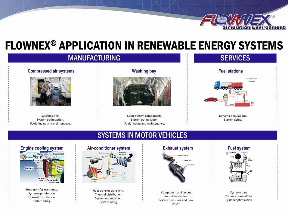
FLOWNEX® APPLICATION IN RENEWABLE ENERGY SYSTEMS MANUFACTURING SERVICES
TRANSPORTATION SYSTEMS IN MOTOR VEHICLES
Compressed air systems
System sizing. System optimization.
Fault finding and maintenance.
Washing bay
Sizing system components. System optimization.
Fault finding and maintenance.
Fuel stations
Dynamic simulations. System sizing.
Engine cooling system Exhaust system Air-conditioner system Fuel system
Heat transfer transients. System optimization. Thermal distribution.
System sizing.
Component and layout feasibility studies.
System pressures and flow losses.
Heat transfer transients. Thermal distribution. System optimization.
System sizing.
System sizing. Dynamic simulations. System optimization.