Embed Size (px)
Citation preview

1
Driver Recert 2012 Topics
• Update on Fire Hose Friction Loss Coefficients
• Fire Flow Through Long LDH Supply Lines
• Rural Water Supply Flow Rates
• Booster Tank Fill Rate Data
• Engine Deck Gun Flow Rate Data
• Tower Monitor Flow Rate Data
• Rescue 351 Topics
• Other Stuff in General
2
Fire Hose Friction Loss CalculationChanges Are On the Way
Fire Protection Research Foundation (supports the NFPA)
Project: “Developing Friction Loss Coefficients For Modern Fire Hose” Start: Jun 2010 Expected Completion: Fall 2011
Summary: Current baseline friction loss coefficients used to calculate fire hose pressure loss were derived using 50 year-old hose design technology. Modern fire hose has substantially less friction loss and different performance characteristics than the hose on which these coefficients were originally based. Calculating pressure loss in modern fire hose cannot be done with reasonable accuracy using currently recognized friction loss coefficients. Pressures that are calculated with these current coefficients are typically higher than those which occur in practice In some cases this could result in elevated and potentially dangerous nozzle pressures.
Research Objective: This project will develop baseline friction loss coefficients for the
types of fire hose commonly used by today’s fire service, and identify any additional performance characteristics that should be considered for friction loss calculations.
Affected NFPA Documents: This project directly addresses a topic specifically covered
by NFPA 1961, Standard on Fire Hose (2007 edition). The friction loss characteristics of fire hose are an important consideration in the selection of fire hose but are not currently included in NFPA 1961. The next revision of this standard will address the friction loss characteristics to include updated values for the friction loss coefficients for modern fire hose.
3
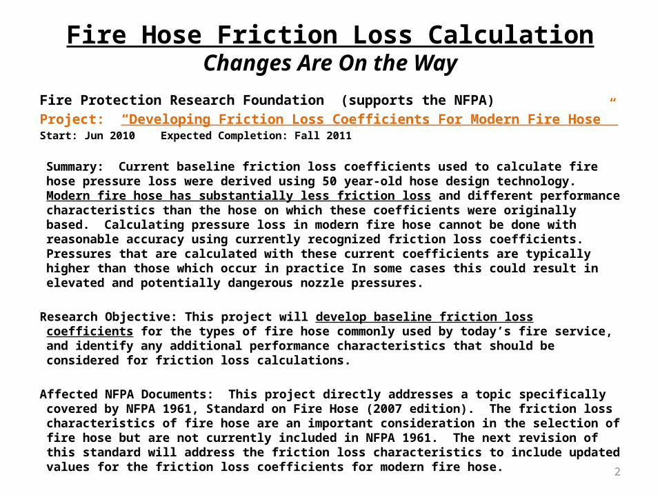
Determination of Fire Hose Friction Loss Characteristics Final Report
Prepared by:
Joseph L. Scheffey, Eric W. Forssell and Matthew E. Benfer
Hughes Associates, Inc. Baltimore, Maryland
© April 2012 Fire Protection Research Foundation
THE FIRE PROTECTION RESEARCH FOUNDATION ONE BATTERYMARCH PARK QUINCY, MASSACHUSETTS, U.S.A. 02169-7471 E-MAIL: [email protected] WEB: www.nfpa.org/Foundation
• Overall objective of research project was to develop friction loss char of modern fire hose and use new FL data to support the revision of the FL coefficients
• Current FL coefs based on old hose mfg technology are considered to be outdated and overly conservative
• Tests conducted at 3 different test sites from Oct 2010 thru Sep 2011, final report was issued in Apr 2012
• Six hose manufacturers participated in tests: Key, Angus-UTC, All American/Snap-tite, Mercedes, and North American
• Test results indicated that the majority of the FL coefs for today’s fire hose fall significantly below current values
Conclusion: A fairly large degree of variability was observed in the test data. A more thorough statistical analysis is necessary for identifying statistically significant trends. Additional testing may be required to support the analysis.
4
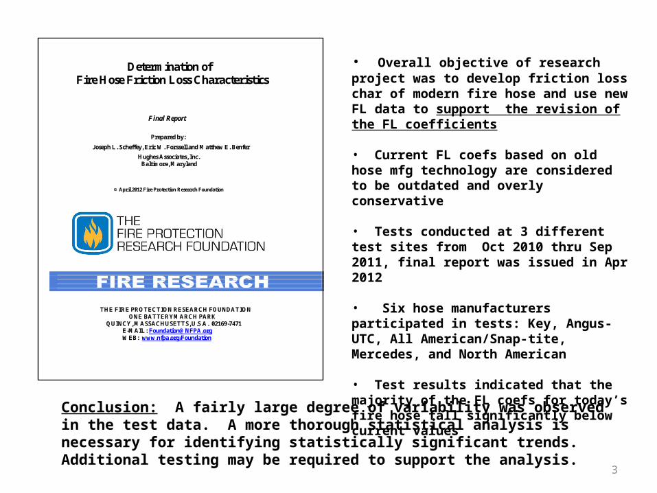
Friction Loss Coefficients
• Friction Loss Formula: FL = C(Q/100)2(L/100)• FL Coefficients (C) Currently Used by the BAVFC:
For 3” hose, we normally use C = 1.0 for FL calculations in the field For 4” LDH, we take 1/5 of the FL for 3”; C = 1/5 = 0.2 For 5” LDH, we take 1/15 of the FL for 3”; C = 1/15 = 0.07 We don’t calculate FL for the 1-3/4” handlines, EP = 150 psi
• Current Standard FL Coefficients: 1-3/4” hose: C = 15.5 3” hose: C = 0.8 4” LDH: C = 0.2 5” LDH: C = 0.08
• FL Coefficients for New Hose Based on Mfgs Estimates: 1-3/4” hose: C = 8.0 (Ponn Conquest Hose) 3” hose: C = 0.4 4” LDH: C = 0.091 (1/11) 5” LDH: C = 0.033 (1/30) (Key Fire Hose)

5
Example of Reduced Friction Loss in Modern Fire Hose
• Recent rural water supply test conducted in Rincon, GA to support ISO
• Determined how much water flow can be provided through a very long 5” LDH supply line
• Several engines laid a 6,000 ft. 5” supply line
• What is the maximum water flow (GPM) that can realistically be supplied through this supply line?

6
Hydrant Location
Hydrant Static
Pressure
Hydrant Residual Pressure
Pump Intake Valve Used
Pump In Gear
Tank Fill Rate
Enterprise Ct.
(Box 313)45 psi
35 psi 2-1/2” Aux NO 215 GPM
20 psi 2-1/2” Aux YES 375 GPM
35 psi 2-1/2” DTF - 375 GPM
Selvin Dr. (Box 321)
90 psi
70 psi 2-1/2” Aux NO 300 GPM
70 psi 2-1/2” Aux YES 375 GPM
70 psi 2-1/2” DTF - 575 GPM
KEY COMPARISON:
Filling the tank with 3” line into the Direct Tank Fill intake at 100 psi intake pressure takes about 1 min 15 sec for a fill rate of 600 GPM Filling the tank using the regular Tank Fill valve with pump discharge pressure at 100 psi takes about 2 min for a fill rate of 375 GPM
Booster Tank Fill Rate Test
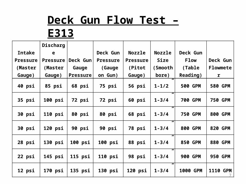
7
Intake Pressure (Master Gauge)
Discharge Pressure (Master Gauge)
Deck Gun Gauge
Pressure
Deck Gun Pressure
(Gauge on Gun)
Nozzle Pressure
(Pitot Gauge)
Nozzle Size
(Smoothbore)
Deck Gun Flow
(Table Reading)
Deck Gun Flowmeter
40 psi 85 psi 68 psi 75 psi 56 psi 1-1/2” 500 GPM 580 GPM
35 psi 100 psi 72 psi 72 psi 60 psi 1-3/4” 700 GPM 750 GPM
30 psi 110 psi 80 psi 80 psi 68 psi 1-3/4” 750 GPM 800 GPM
30 psi 120 psi 90 psi 90 psi 78 psi 1-3/4” 800 GPM 820 GPM
28 psi 130 psi 100 psi 100 psi 88 psi 1-3/4” 850 GPM 880 GPM
22 psi 145 psi 115 psi 110 psi 98 psi 1-3/4” 900 GPM 950 GPM
12 psi 170 psi 135 psi 130 psi 120 psi 1-3/4” 1000 GPM 1110 GPM
Deck Gun Flow Test – E313

8
Intake Pressure (Master Gauge)
Discharge Pressure (Master Gauge)
Deck Gun Gauge
Pressure
Deck Gun Pressure
(Gauge on Gun)
Nozzle Pressure
(Pitot Gauge)
Nozzle Size
(Smoothbore)
Deck Gun Flow
(Table Reading)
Deck Gun Flowmeter
80 psi 110 psi 88 psi Inoperative 64 psi 1-3/4” 727 GPMVery High, Inaccurate Readings
80 psi 128 psi 100 psi 80 psi 1-3/4” 813 GPM
78 psi 125 psi 110 psi 86 psi 1-3/4” 843 GPM
75 psi 150 psi 125 psi 98 psi 1-3/4” 900 GPM
72 psi 182 psi 150 psi 120 psi 1-3/4” 1000 GPM
70 psi 140 psi 100 psi 70 psi 2” 994 GPM
68 psi 160 psi 120 psi 80 psi 2” 1063 GPM
Deck Gun Flow Test – E314
9
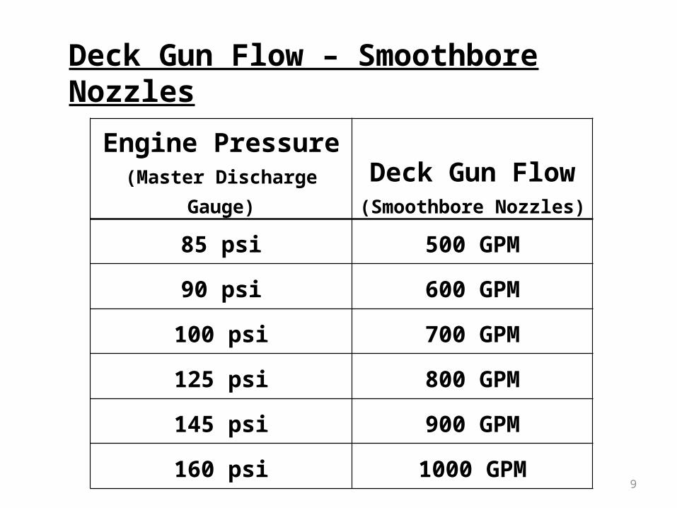
Engine Pressure (Master Discharge Gauge)
Deck Gun Flow(Smoothbore Nozzles)
85 psi 500 GPM
90 psi 600 GPM
100 psi 700 GPM
125 psi 800 GPM
145 psi 900 GPM
160 psi 1000 GPM
Deck Gun Flow – Smoothbore Nozzles
10
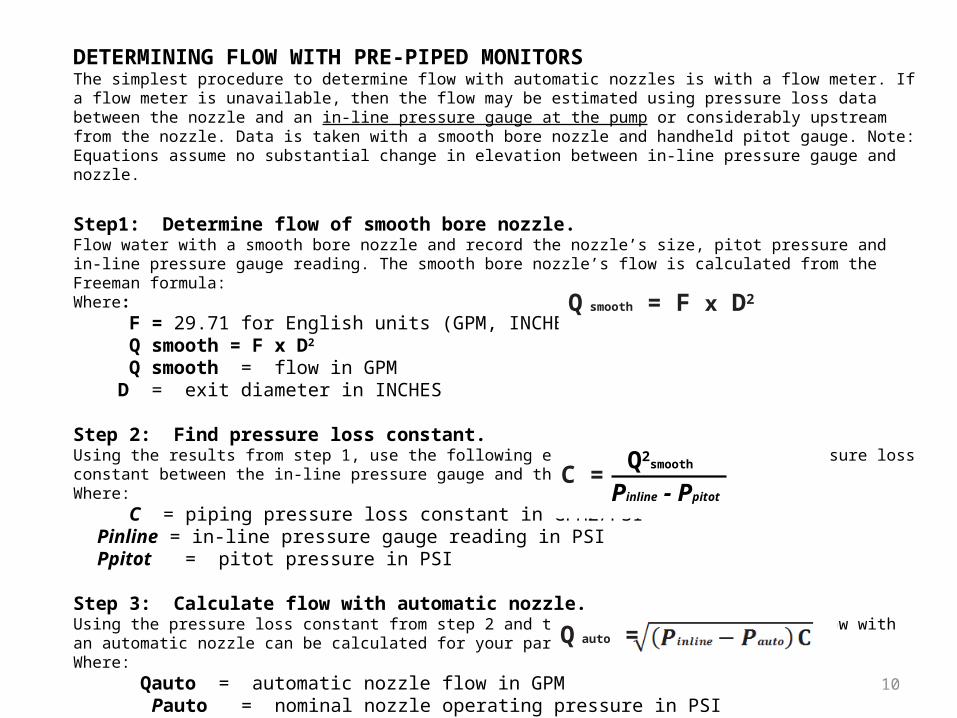
DETERMINING FLOW WITH PRE-PIPED MONITORSThe simplest procedure to determine flow with automatic nozzles is with a flow meter. If a flow meter is unavailable, then the flow may be estimated using pressure loss data between the nozzle and an in-line pressure gauge at the pump or considerably upstream from the nozzle. Data is taken with a smooth bore nozzle and handheld pitot gauge. Note: Equations assume no substantial change in elevation between in-line pressure gauge and nozzle.
Step1: Determine flow of smooth bore nozzle.Flow water with a smooth bore nozzle and record the nozzle’s size, pitot pressure and in-line pressure gauge reading. The smooth bore nozzle’s flow is calculated from the Freeman formula:Where: F = 29.71 for English units (GPM, INCHES, PSI) Q smooth = F x D2
Q smooth = flow in GPM D = exit diameter in INCHES
Step 2: Find pressure loss constant.Using the results from step 1, use the following equation to calculate the pressure loss constant between the in-line pressure gauge and the nozzle: Where: C = piping pressure loss constant in GPM2/PSI Pinline = in-line pressure gauge reading in PSI Ppitot = pitot pressure in PSI
Step 3: Calculate flow with automatic nozzle.Using the pressure loss constant from step 2 and the following equation, the flow with an automatic nozzle can be calculated for your particular installation.Where: Qauto = automatic nozzle flow in GPM Pauto = nominal nozzle operating pressure in PSI
Q smooth = F x D2
Q auto =
C = Q2
smooth
Pinline - Ppitot
11
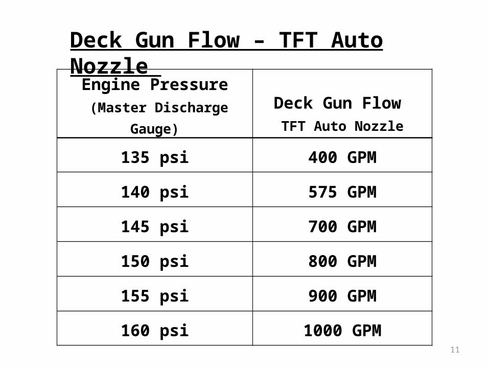
Engine Pressure (Master Discharge Gauge)
Deck Gun Flow TFT Auto Nozzle
135 psi 400 GPM
140 psi 575 GPM
145 psi 700 GPM
150 psi 800 GPM
155 psi 900 GPM
160 psi 1000 GPM
Deck Gun Flow – TFT Auto Nozzle
12
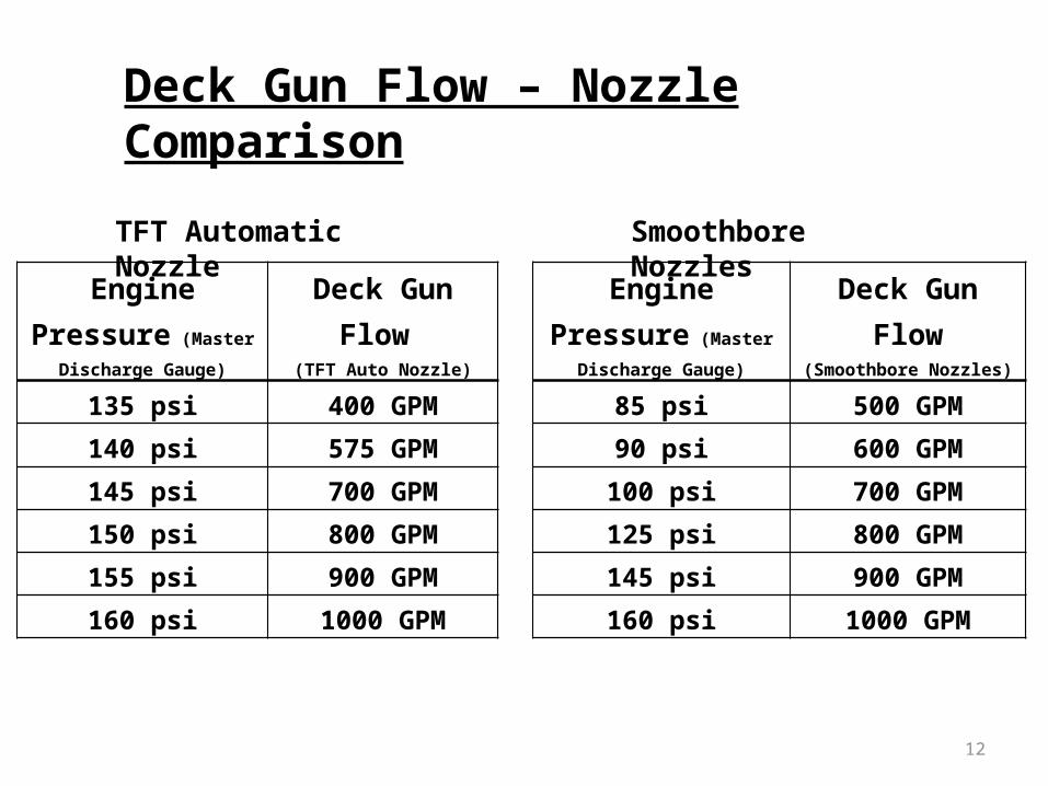
Engine Pressure
(Master Discharge Gauge)
Deck Gun Flow(Smoothbore Nozzles)
85 psi 500 GPM
90 psi 600 GPM
100 psi 700 GPM
125 psi 800 GPM
145 psi 900 GPM
160 psi 1000 GPM
Engine Pressure
(Master Discharge Gauge)
Deck Gun Flow (TFT Auto Nozzle)
135 psi 400 GPM
140 psi 575 GPM
145 psi 700 GPM
150 psi 800 GPM
155 psi 900 GPM
160 psi 1000 GPM
Deck Gun Flow – Nozzle Comparison
TFT Automatic Nozzle Smoothbore Nozzles

13
Intake Pressure
(Tower Intake Valve)
Monitor Flow(Single Monitor)
120 psi 600 GPM
135 psi 800 GPM
175 psi 1000 GPM
195 psi 1250 GPM
220 psi 1500 GPM
250 psi* 1600 GPM
Intake Pressure
(Tower Intake Valve)
Monitor Flow(Two Monitors Flowing)
105 psi 1000 GPM
140 psi 1200 GPM
185 psi 1600 GPM
200 psi 1800 GPM
250 psi* 2000 GPM
Single Monitor Flowing Both Monitors Flowing
*Pressure relief valves on Tower intake valve and waterway opening
Tower Monitor Flow Rates
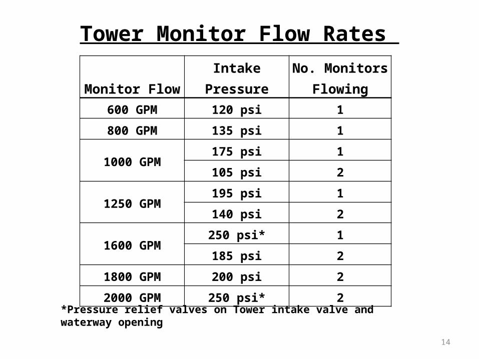
14
Monitor Flow Intake
PressureNo. Monitors
Flowing600 GPM 120 psi 1
800 GPM 135 psi 1
1000 GPM175 psi 1
105 psi 2
1250 GPM195 psi 1
140 psi 2
1600 GPM250 psi* 1
185 psi 2
1800 GPM 200 psi 2
2000 GPM 250 psi* 2
*Pressure relief valves on Tower intake valve and waterway opening
Tower Monitor Flow Rates
15
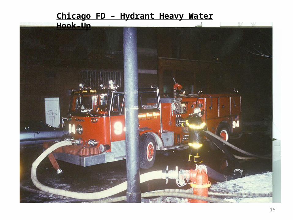
Chicago FD – Hydrant Heavy Water Hook-Up
16
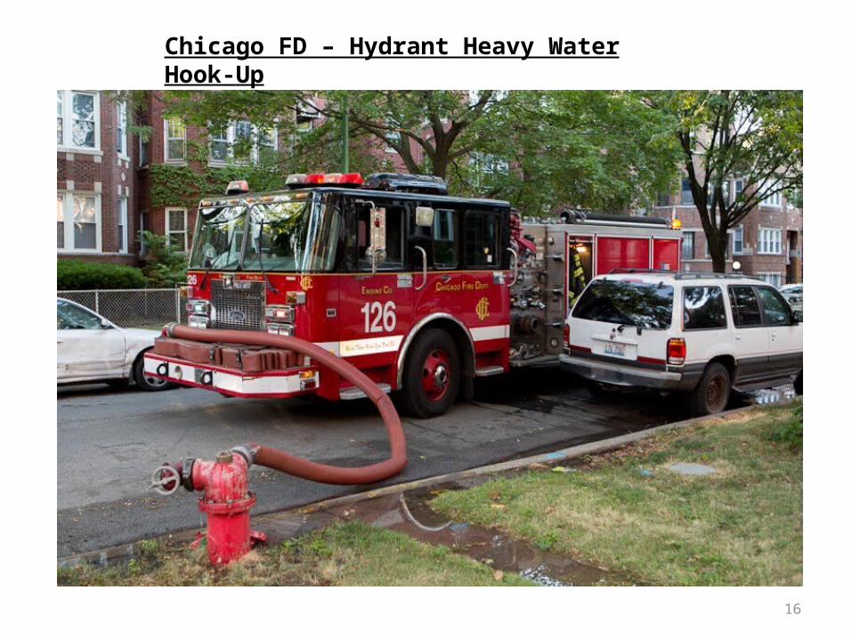
Chicago FD – Hydrant Heavy Water Hook-Up
17
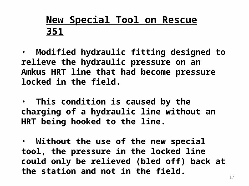
New Special Tool on Rescue 351
• Modified hydraulic fitting designed to relieve the hydraulic pressure on an Amkus HRT line that had become pressure locked in the field.
• This condition is caused by the charging of a hydraulic line without an HRT being hooked to the line.
• Without the use of the new special tool, the pressure in the locked line could only be relieved (bled off) back at the station and not in the field.
18
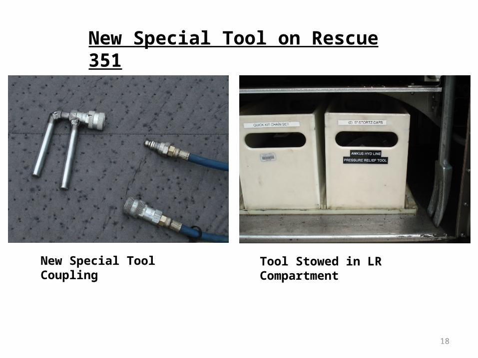
New Special Tool on Rescue 351
New Special Tool Coupling Tool Stowed in LR Compartment

19
Pressure Relieved on E314 Line Pressure Relieved on R351 Line
20
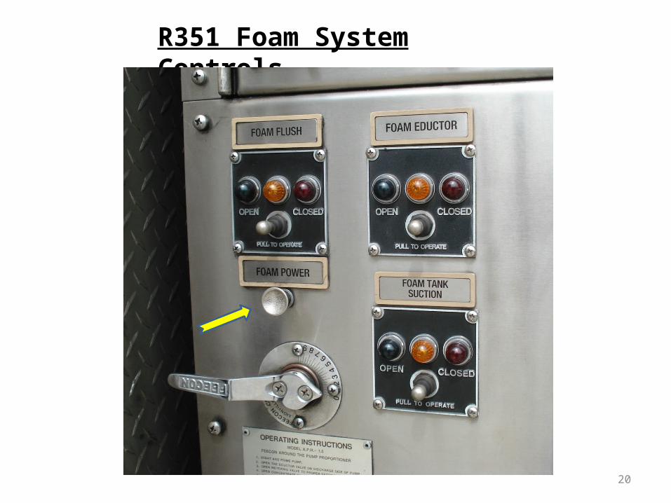
R351 Foam System Controls
21
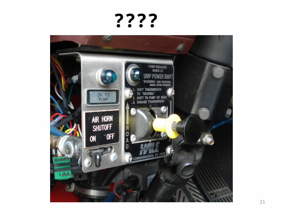
????

22
Other Stuff in General
• What’s unique about the Siren Brake on TW331?
• What’s different about the Transmission Mode control on TW331 and R351 compared to all of the other apparatus?
• If you turn OFF the Auxiliary Braking Device (Jake Brake or Trans Retarder) in rainy weather, what should you also do regarding your driving?
• What should a good EVD always do immediately following each run?