Embed Size (px)
Citation preview
THE DISTRIBUTED CONTROL SYSTEM WITH DECENTRALIZED ACCESS TO AN OPTICAL BUS FOR THE MILAN SUPERCONDUCTING CYCLOTRON
F.Aghion *, G.Cuttone ***, D.Giove ** ,A.Paccalini**,G.Rivoltella *
* ) Department of Physics - University of Milan ** ) National Institute for Nuclear Physics - Milan ***) INFN - Laboratorio Nazionale del Sud - Catania
Abstract. Modern control system designs for accelerating machines, can take advantage of the ever growing progress in microprocessor and VLSI technology, when using, where possible, widely accepted international standards, either for the hardware equipment or for the software.
In this paper, detailed discussion on how this concept has been applied to the control system for the Milan Superconducting Cyclotron (1 ) will be provided.
l.Introduction
The main features of an ideal computer control system for a new accelerating machine, whose design starts as soon as the machine construction is beginning, must take into account some important rules.
In a first stage it should only be an auxiliary tool for each single apparatus development and testing; user-friendly operation, reliability, possibility of working in a stand-alone mode and an easy access to host computers and to printing, plotting and recording devices are major requirements.
In a second stage, when the machine has been assembled and first tests are in progress, it should become a complex monitoring system with enhanced display capabilities, a flexible actuator able to operate on each single machine parameter controlled by the electronics by means of manual commands and a computing tool for analyzing data.
Operating the machine in a manual way means giving commands, set points or modified parameters through interactive devices, filtered by computers in such a way that in a future closed-loop control, substitution of the operator by programs could be simplified.
The third stage starts when the control loops begin to be closed. Experience on the accelerator operation must be acquired to write control programs for optimizing beam performances.
Moreover an accelerating machine need to be supported by a very complex technical environment . Integration of the accelerating machine control system with a controller dedicated to all the auxiliary technical plants gives undoubted benefits to the overall reliability.
Last, but not less important, an economical consideration: an accelerating machine project may take several years since the design specifications to the full operation, but computer technology is making progresses very fast, with decreasing costs. The computer control designer must take care of this, when choosing his architecture, so to be able to modify his standard hardware to get benefit of such an evolution without loosing his investment in specialized hardware and, what is most important, in software development.
2.Design features and system lay-out
Microcomputers technology dramatic modifications in the field.
advent, has accelerators
produced control
Today, microprocessors can be directly incorporated
in the interface between computers and the machine equipment, or can be the core of powerful units able to control complex apparata. According to this, even a long established standard for accelerators laboratories as CAMAC, has to give way to modern buses.
In the majority of new designs , centralized control architectures whith single master protocol have been substituted by multicomputers systems.(3), IS)
When distributing computing power in peripheral control stations, two main possible criteria derives:
the geographical criterion: equipments located in a same area are put under control of a single unit, so to minimize cables length, reduce noi se in analogue values transmission, and simplify trouble shooting and maintenance . Such a solution is significant for large accelerating machines where distances among equipments can even be of the order of kilometers . the functional criterion: similar equipments (for example a set of power supplies) , or a complete accelerating machine subset (for example the R.F. system) are organized under the control of a single computing uni t. For the Milan project, the functional criterion has
been considered effective, due to the compact size of the Superconducting Cyclotron.
Moreover, as critical interlocks and severe real-time applications are under the control of single peripheral units, independent operation can be provided in case of failure on the network.
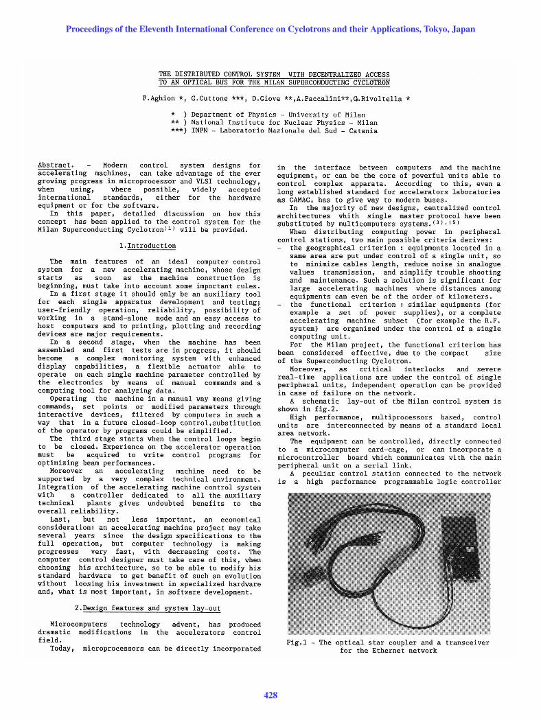
A schematic lay-out of the Milan control system is shown in fig . 2.
High performance, multiprocessors based, control units are interconnected by means of a standard local area network.
The equipment can be controlled, directly connected to a microcomputer card-cage, or can incorporate a microconttoller board which communicates with the main peripheral unit on a serial link.
A peculiar control station connected to the network is a high performance programmable logic controller
Fig.1 - The optical star coupler and a transceiver for the Ethernet network
Proceedings of the Eleventh International Conference on Cyclotrons and their Applications, Tokyo, Japan
428
/", VAX I I
'---PROGR~~.~-~~ LOGIC PL AN T 5
CONTROLLER
HPPC 1500 j
FIBER OPTIC IEEE 802.3
SBC>861" ~ ~
PLANTS II 1'1 ~ ~~-- - rrsb.
~ PLANTS ~
==-=-=IIIiI~T --~- :-- :'-==--=====I~
~Ii~ a:S a:b VACUUM CONTROL BEAM DIAGNOSTIC
TRIM CO ilS CONTROL airBUS MICROCONTROlLEAS
Fig.2 - The control system architecture
which takes care of the technical plants through Serial Interface Modules for industrial 1/0 boards driving.
At a higher level, a host computer (DEC, ~Vax II) at the moment provides file storage, printing, programs development tools, network monitoring and start-up procedures.
A console node, designed in a modular construction, provides fast access to every machine parameters by means of interactive devices. An auxiliary connection with the host computer through a DMA channel for high-speed data transfer has been implemented.
Operating systems on EPROM are an important improvement. A nucleus of the iRMX 86 operating system has been installed in every high level CPU boards.
Standard communication firmware has been adopted either for the local area network (iNA 960), or for the serial bus (Bitbus) .
3.The optical network
In a distributed environment the network becomes a critical element; the choice of topology, protocol, data rate, and transmission media can affect the overall performance of the control system.
The following features are to be considered : reliability: hardware components must be insensitive to inductive and cross-talk interferences. broadcasting: the possibility of sending data or timing informations, simultaneously to every connected node . access: every unit can directly communicate with any other unit standard protocol: it integrated components to easily interface manufacturers.
allows to get benefit of available on the market, and equipments from different
A good compromise for all these requirements has been found using the IEEE 802.3 standard communication protocol (Ethernet)(4). An optical transmission medium has been preferred to the standard coaxial cable.
Ethernet provides a bit rate of 10 Mbits/sec. and uses a Carrier Sense, Multiple Access with Collision
Detection (CSMA/CD) technique. A couple of drawbacks in the Ethernet standard seems
to be undesirable for control systems : the CSMA/CD technique does not guarantee access to the network in a predictable time, due to the collision resolving method; that is significant in case of a very large number of nodes (>100) or when severe synchronizations are to be performed through the network. throughput performances of the Ethernet protocol, which are excellent for large amount of data transmission, decrease for short messages, due to a fixed overhead in both software and hardware controller. These limitations are not significant for the Milan
control system, as at full operation the number of nodes should be lower than 20; moreover the time critical control is performed by the peripheral control stations.
Optical transmission media, made up by silica graded index optical fibers in a two cord assembly (100~m. core 140~m.cladding ), have been preferred to the standard coaxial cable for E.M.I. insensitivity and for complete isolation among the nodes.
The interface between the optical bus and the Ethernet electronic components is performed by an optical transceiver (Codenoll Technology Corp.).
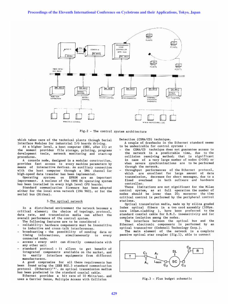
The main element of the network is a complete passive optical star coupler (fig.1), able to connect
c, t
Ac
Fig.3 - Flux budget schematic
Proceedings of the Eleventh International Conference on Cyclotrons and their Applications, Tokyo, Japan
429
up to sixteen nodes with a flux budget of 27 dB (fig.3).
The following flux budget calculation guarantees a reliable operation, taking into account temperatures variations or components aging :
Star coupler loss (SL) Flux budget margin (M) Fiber loss attenuation (Af) Connectors losses (Ac) Maximum length between the Coupler and a transceiver (LMAX )
13 dB.Typical 3 dB. 6 dB./Km. 1. 5 dB. 0.3 Km.
Exaustive tests have demonstrated a good reliability of the hardware; a bit error rate < 1.10- 9 has been measured.
4.The peripheral control stations
The peripheral control stations (PCS) have been designed to perform high-speed data acquisition from sensors, to acquire a large number of machine parameters, to convert measurements to physics units for database updating and video monitoring and to provide complex real-time controls. )~ .
These units dedicated to a functional partltlon of the Cyclotron can operate either connected to the main control network or in a stand-alone mode. This latter feature is useful during the hardware design, testing, maintenance and trouble-shooting. In such cases, the unit can be driven by a personal computer for giving commands, displaying messages and recording data .
Some rules for the hardware have been defined in the architecture of the PCS; the card-cage bus is the standard IEEE 796 (Multibus 1(6) and the CPUs are from the Intel family of high-performance sixteen bits microprocessors.
Such a set of rules has given a fantastic flexibility in each PCS configuration, due to the enormous amount of products available on the market. In fact it is possible to expand the card-cage from eight to sixteen slots, add memory up to the logic adressing limit, increase the number of the CPUs, or substitute an older single board computer ( for example an SBC 86/14 ) with a newer SBC 286/12 with trivial modifications.
In fig. (4) represented, in shown :
a typical structure of a PCS is which the following main sections are
the communication board: an Intel iSBC 186/51 has been selected as the standard interface between the PCSs and the Ethernet network. Network services are managed by application programs (burned on EPROMs),
Fig.4 - A PCS internal architecture
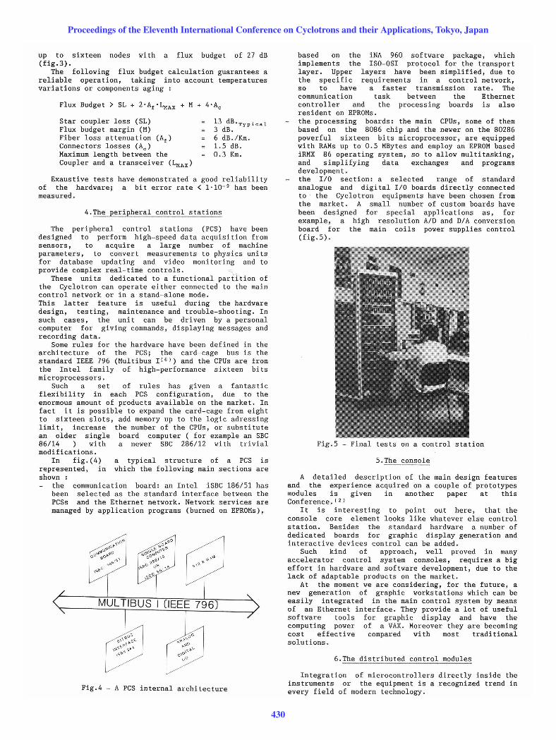
based on the iNA 960 software package, which implements the ISO-OSI protocol for the transport layer . Upper layers have been simplified, due to the specific requirements in a control network, so to have a faster transmission rate. The communication task between the Ethernet controller and the processing boards is also resident on EPROMs. the processing boards: the main CPUs, some of them based on the 8086 chip and the newer on the 80286 powerful sixteen bits microprocessor, are equipped with RAMs up to 0.5 MBytes and employ an EPROM based iRMX 86 operating system, so to allow multitasking, and simplifying data exchanges and programs developmen t . the 1/0 section: a selected range of standard analogue and digital 1/0 boards directly connected to the Cyclotron equipments have been chosen from the market. A small number of custom boards have been designed for special applications as, for example, a high resolution AID and DIA conversion board for the main coils power supplies control (fig.5).
Fig.5 - Final tests on a control station
5.The console
A detailed description of the main design features and the experience acquired on a couple of prototypes modules is given in another paper at this Conference. (2)
It is interesting to point out here, that the console core element looks like whatever else control station. Besides the standard hardware a number of dedicated boards for graphic display generation and interactive devices control can be added.
Such kind of approach, well proved in many accelerator control system consoles, requires a big effort in hardware and software development, due to the lack of adaptable products on the market.
At the moment we are considering, for the future, a new generation of graphic workstations which can be easily integrated in the main control system by means of an Ethernet interface. They provide a lot of useful software tools for graphic display and have the computing power of a VAX. Moreover they are becoming cost effective compared with most traditional solutions.
6.The distributed control modules
Integration of microcontrollers directly inside the instruments or the equipment is a recognized trend in every field of modern technology.
Proceedings of the Eleventh International Conference on Cyclotrons and their Applications, Tokyo, Japan
430
A summary of the benefits of such a design follows: it allows to convert to digital signals every analogue parameter, as near as possible to the transducer, thus avoiding to transmit at long distances analogue low-level values. a further distribution of intelligent components increases the overall reliability; in fact a local failure does not affect the complete system. specializing hardware and software very specific tasks, a higher modularity and easier enhancements can be achieved. extensive use of cheap microcontrollers does not affect in a sensible way the overall cost of the project. After having accepted these concepts, the next step
consists in finding a good connection method, as traditional ones like RS232-C or current loop or IEEE 488 do not provide sufficient performance or are not adequate for long distances.
Ye recently decided to adopt the standard BITBUS interconnect which is a serial bus optimized for high speed transmission of short messages.
Main features are the following Electrical standard : RS485 Cable : at the moment 2 wire twisted pair, in a next future optical fibers Mechanical form factor : single-height Eurocard Transfer rate: up to 2.4 Mbaud The serial bus support up to 250 nodes. Communication protocol is standard and firmware based. BITBUS(6) is a hierarchical system with a master and
a number of slaves. Master boards for Intel-based systems and for IBM personal computers are now available on the market with software tools running under the iRMX 86 operating system and the MS.DOS . In a near future a Q-bus master board for a ~VAX II computer will be tested (fig.6).
First applications in progress power supplies control, displays interface drivers, motors controllers node design.
~' '::,::0 _____ \~ ,
l"lu' I L __ .J .. un" I
at the moment are and man-machine
and a IEEE 488
Fig.6 - Bitbus architecture with available masters
7.Technical plants
As for most accelerating machines, Superconducting Cyclotrons operation depends on a large number of auxiliary technical plants. Helium refrigerator, liquid helium and liquid nitrogen distribution, water cooling systems, electric installation and heating plants are some of the most significant.
Ye are convinced of the benefit of having all these plants under control, associated with a powerful monitoring system.
Integration of the machine control system with the technical installations controller guarantees better reliability of the complete plant.
A large number of controllers are available on the market due to a strong industrial demand. Ye made our choice for a Yestinghouse high performance programmable
TEMPERATURES PRESSURES
" NO STRESSES CONTROL
h
}A YAX II
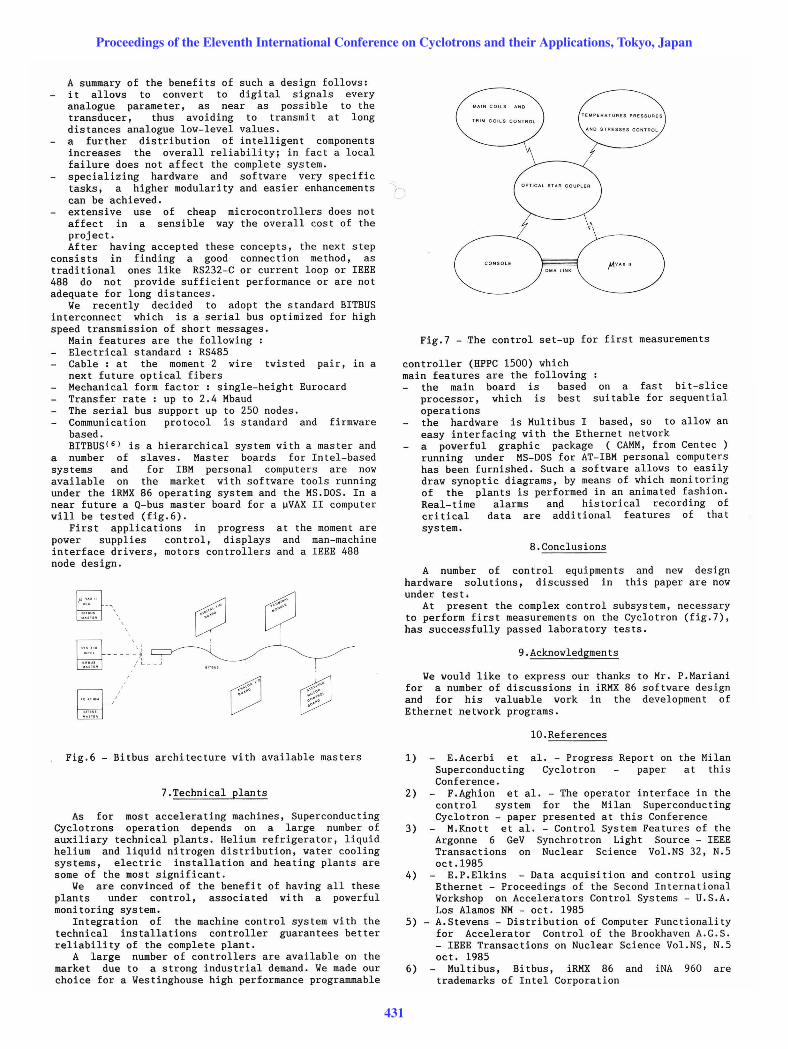
Fig.7 - ~he control set-up for first measurements
controller (HPPC 1500) which main features are the following
the main board is based on a fast bit-slice processor, which is best suitable for sequential operations the hardware is Multibus I based, so to allow an easy interfacing with the Ethernet network a powerful graphic package (CAMM, from Centec ) running under MS-DOS for AT-IBM personal computers has been furnished. Such a software allows to easily draw synoptic diagrams, by means of which monitoring of the plants is performed in an animated fashion. Real-time alarms and historical recording of critical data are additional features of that system.
8.Conclusions
A number of control equipments and new design hardware solutions, discussed in this paper are now under test.
At present the complex control subsystem, necessary to perform first measurements on the Cyclotron (fig.7), has successfully passed laboratory tests.
9.Acknowledgments
Ye would like to express our thanks to Mr. P.Mariani for a number of discussions in iRMX 86 software design and for his valuable work in the development of Ethernet network programs.
10.References
1) E. Acerbi et al. - Progress Report on the Milan Superconducting Cyclotron paper at this Conference.
2) F.Aghion et al. - The operator interface in the control system for the Milan Superconducting Cyclotron - paper presented at this Conference
3) M. Knott et al. - Control System Features of the Argonne 6 GeV Synchrotron Light Source - IEEE Transactions on Nuclear Science Vol.NS 32, N.5 oct. 1985
4) E. P.Elkins - Data acquisition and control using Ethernet - Proceedings of the Second International Yorkshop on Accelerators Control Systems - U.S.A. Los Alamos NM - oct. 1985
5) - A.Stevens - Distribution of Computer Functionality for Accelerator Control of the Brookhaven A.G.S. - IEEE Transactions on Nuclear Science Vol.NS, N.5 oct. 1985
6) Multibus, Bitbus, iRMX 86 and iNA 960 are trademarks of Intel Corporation
Proceedings of the Eleventh International Conference on Cyclotrons and their Applications, Tokyo, Japan
431