Embed Size (px)
Citation preview
ACCELERATION OF RADIOACTIVE ION BEAMS IN CYCLOTRONS*
M.L. Mallory National Superconducting Cyclotron Laboratory
Michigan State University East Lansing, MI 48824-1321
Abstract The prod uction of radioactive ion beams is
reviewed. The major emphasis of this paper is on the cyclotron analogue beam method, which utilizes the capability of a high energy heavy ion cyclotron. The demonstration of this technique with the K500 cyclotron at Michigan State University is reported, where beams
of 3H1+ and 6He2+ have now been successfully produced. The future portends a large development in the production of radioactive ion beams at high energy.
Introduction The past 20 years has seen a tremendous growth in
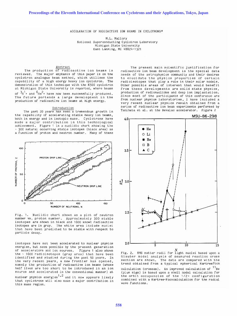
the capability of accelerating stable heavy ion beams, both in energy and in isotopic mass. Cyclotrons have made a major contribution in this technological achievement. Figure 1 is a nuclidic chart showing the - 300 natural occurring stable isotopes (black area) as a function of proton and neutron number. Many of these
100
vi z 0 .... 0 a: Q.
"- 50 0 a: ... CD ~ ::J Z
NUMBER OF NEUTRONS, N
Fig. 1. Nuclidic chart shown as a plot of neutron number vs. proton number. Approximately 300 stable isotopes are shown in black and 1600 known radioactive isotopes are in gray. The white area include nuclei that have been predicted to be stable with respect to particle decay.
isotopes have not been accelerated to nuclear physics energies, but seem possible by the present generation of accelerators and ion sources. Figure 1 also shows the - 1600 radioisotopes (gray area) that have been identified and studied during the past 50 years. In the very recent years, a new frontier has opened, namely the production of radioactive ion beams (whose half lives are too short to be introduced in an ion source and accelerated in the conventional manner) at
nuclear physics energies 1,2 and it now appears likely that cyclotrons will also make a major contribution in this mass region.
The present main scientific justification for radioactive ion beam development is the special data needs of the astrophysics community and their desires to elucidate the physics properties of certain radioisotopes that playa role in their solar models. Other possible areas of interest that would benefit from these developments are solid state physics, production of radionuclides and deep ion implantation. Since most of the participants of this conference are from nuclear physics laboratories, I have included a very recent nuclear physics result obtained from a series of radioactive ion beam experiments performed by Tanihata et al. at the Bevalac accelerator. Figure 2
4.0
3.S
I ~ 30 c.:: .
2.S
• 0
• 0
•
He Li
Be B
C
I I I I I I I I I
I I , I I I I I I I I I ,
I I I I I I ,
I , I ,
I ,
MSU-86-298
2.0 L-----.;:.S------l-:-rO'--------;lS'
N Fig. 2. RMS matter radii for light nuclei based upon a Glauber model analysis of measured reaction cross section are shown . The data are compared with the trend obtained from a typical spherical HartreeFock
calculation (crosses). An improved calculation of 11 Be (plus sign) is based upon a shell model calculation for the orbit occupancies of the 1/2+ configuration comb ined with a Hartree-Fockcalculation for the radial wave functions.
Proceedings of the Eleventh International Conference on Cyclotrons and their Applications, Tokyo, Japan
558

is a meas urement of t he exper i mental mean nuclear radius as a funct i on of neutron number for various
light radi oactive nuclei . 3 The theoret ical predict i ons of the mean nuclear rad i us for spher i ca l nuc l ei ar e s hown (x - li ne) and does a very poor j ob of predicti ng these resul ts. Al ex Br own f rom Mi chi gan State has
mod i fied ~ hi s model for "Be (cross data point) and i s
getting better agreement . 4 The major po int here is that exper i ments with radioact i ve beams are already making a contribution to our unde r standing of nuclear phys i cs models an d we would expect many more s i nce t hese be ams wi ll test t he models at extreme condi t i ons of nuc l ear matter .
The pr i mary purpose of thi s paper is to repo r t on the various met hods of producing and acce l erating radioact i ve beams . I n the f i rst sect i on I shall br i ef l y descr ibe the t wo accelerator-target ion sour ce met hod. I n the next sect i on I s ha ll repo rt on t he fragmentat i on method of mak i ng radi oact i ve par t i cl es and finally I shall conclude with the cyc l otron analogue beam technique.
Two Accelerator - Target I on Source Method The initial concept of making a rad i oact i ve ion
beam, requI res an energet i c 1st stage accel erator , wi t h its beam bombar di ng a tar get . The radi oactive isotopes made at the t arget migrates to an ion so urce and are ionized, extracted and accelerated in a 2nd stage accelerator.
The f i rst part of this technique has been amply
demonst r a te d at the Cer n I SO LDE f aci lit y5, whe r e a prot on beam bombards a target l ocated in the ion sour ce of a mass separator . Fi gure 3 is a shortened version
MSU-86- 297
10 • 9
8 '"' !:::!. 7
en 6 c: 0 - 5 0 ... a.. 4
3
2 He
H 2 3 4 5 6 7 8 9 10 II 12 13 14
Neutrons (N)
Fig. 3. A shortened n ucl i dic chart of the l i gh t radioactive isotopes pr oduced at the I SOLIDE faci li ty in Cern are shown i n dark . The i sotopes were made wit h a pr ot on beam.
of the nucl i dic chart show i ng the rad i oact i ve l i ght isotopes made at thi s faci l ity. Heavy ion accel erators have a l so been used to make radioact i ve ions i n a target i on source and Fi g. 4 is a pi ct ur e of t he Unisor
facility6 a t Oak Ridge . The heavy i ons are accel erated in ORIC or the 25MV el ect rostat ic tandem accelerat or.
F i g . 4. A photogr aph of the Unisor facility at Oak Ridge. Heavy ions have been used at this fac i lity to make radioact i ve i sot opes.
Figure 5 i s a 10 year old schematic drawing of the
central region of the Oak Ridge ORIC cyclotron7 , showi ng the calculated orbi t of a beam from the tandem accelerator being i njected into the ion source of the cyclotron. It was pr oposed that radioactive i ons would be made in this ion source , extracted and accelerated in the ORIC. This is the first proposal of using a cyclotron to accelerate rad i oact i ve ions to nuclear physics type energies . "This proposal has not been implemented at Oak Ri dge .
H 1 em
DEE ION SOURCE
ARC CHAMBER WITH
TARGET MATERIAL
ORIC ACCELERATED RADIOACT IV E BEAM
- --I- <t-
ACCELERATING ELECTRODE
ARC PL ASMA
Fi g . 5. A median plane view of the central region of the ORIC. The injected beam would impinge upon a target l ocated next t o the arc plasma column of a cold ca thode ion source. Radi oactive i ons produced in the target woul d diffuse into the plasma column, be ionized , extracted and accelerated in the cyclotron .
Next I show a schematic drawi ng (Fig. 6) of an ion source facili ty that i s be i ng cons t r ucted at the Tr i umf
La bor a tory. 8 This f igure shows a target ion source ( propos ed to be an ECR type) where the very intense Tri umf proton beam will be used to produce rad i oact i ve
Proceedings of the Eleventh International Conference on Cyclotrons and their Applications, Tokyo, Japan
559

ions. It is further proposed that the radioactive ions produced in this facility would be extracted and injected into a superconduct.ing accelerator; the type not yet decided. This proposed facility would be an outstanding frontier device for accelerating radioactive ion beams.
Fragmentation - Beam Line Separator With the successful completion of theBevalac, it
was experimentally discovered that the grazing collisions of high energy heavy ion nucleons, resulted in the production of nuclear fragments in large yields.
The measured cross section yieldS 9 for different
fragments obtained from ihteraction of a 2~2 MeV/u 48Ca beam are plotted in Fig. 1. The most abundant cross sections are produced in the tens of millibarn and can potentially lead to large radioactive ion beams. Figure 8 is the integrated fragment production cross section for a variety of masses at three incident
energies. 10 The yields are nearly equal over this range, where the lower ener gy per nucl eon are wi thi n the capabilities of the K500 cyclotron at Michigan State and the Ganil accelerator. Several fragment
angular distributions taken at MSU 11 are illustrated in Fig. 9 and indicates that the fragment production cross sections are sharply peaked in the forward direction of the incident primary beam. These experimental observations have led to the construction of a fragment separator in the external beam line of the Bevalac.
\. ~. ·1 . e ..... " .... ., •
.. -'u ..... :;t. . r"""'"
r ..
-........ . . .... 'ul ""'1. V ••• • .,1',,'
1.IIUtITT ., 111111. UUI.'ll
~~~.'~~~~~~~~77.~~~~~~~~~~01~'~D~.~ac~~~~~
Fig. 6. facility current ions.
.o.&,~ ...... ~..a ........... .... , ....... ...
The planned layout of a target ion source at Triumf is shown. The high intensity proton of Triumf will be used to make radioactive
Neutron number
Fig. 1. The production cross section of neutron rich light isotopes observed in the fragmentation of 212
48 2 MeV/u Ca ion on an 890 mg/cm Be tar~et,.
Msu·a4·401
Ar + Co
42 MeV/NUCLEON
92 MeV/NUCLEON '" t (xIO"(
t"'t+t • 137 MeV/NUCLEON
(xIO-4)
t ••
FRAGMENT MASS
Fig. 8. The integrated fragment production cross section for Ar + Ca as a function of the fragment mass for several beam energies. The lower energies are within the capability of the K500 cyclotron.
Proceedings of the Eleventh International Conference on Cyclotrons and their Applications, Tokyo, Japan
560
101
100
'i i ~ ! Ii 10- 1 ~ "-." "
10-2
'u .n."ln cll.,rtln,tlona
~ • ~.t.I'73
x 8'-1 .••• (-I, el •• Ue) o &,1-1 .134 II 8,-2.13.
MSU-86-307
10 AnIle (eI ••. )
15
Fig. 9. Preliminary angular distribution for 160 + 58
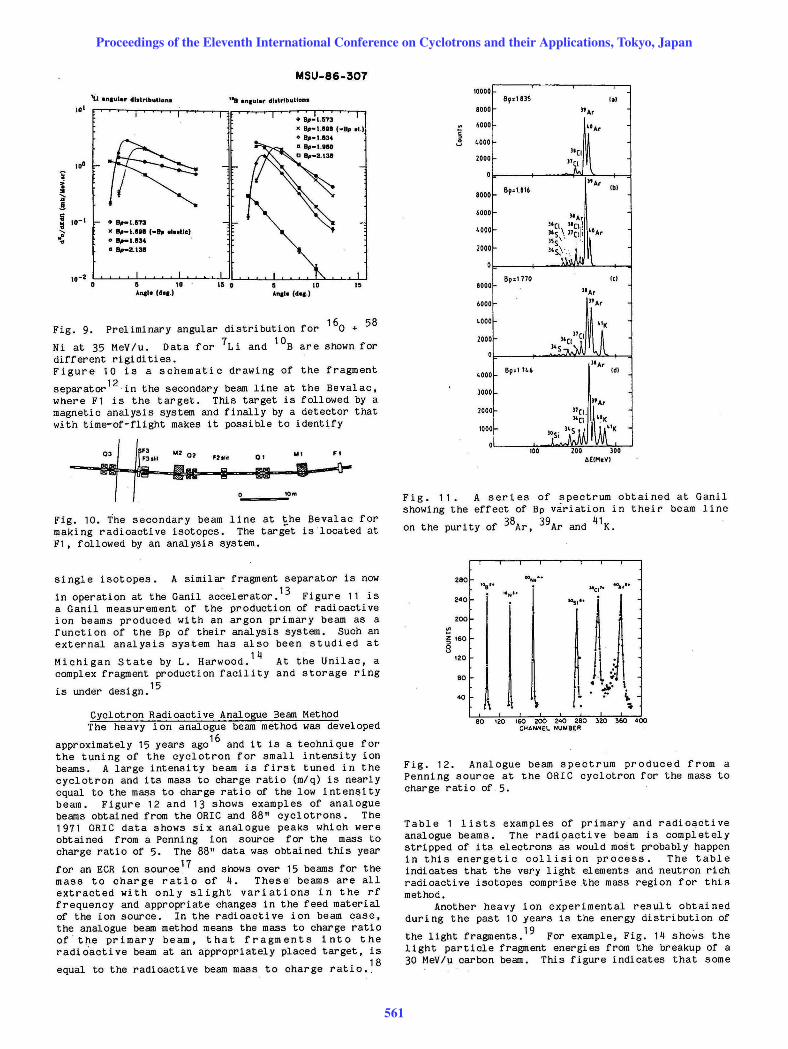
Ni at 35 MeV/u. Data for 7Li and lOB are shown for different rigidities. Figure lOis a schemati c drawing of the fragment
separator12 · in the secondary beam line at the Bevalac, where F1 is the target. This target is followed by a magnetic analysis system and finally by a detector that with time-of-flight makes it possible to identify
03 F2alit o. ... "
Fig. 10. The secondary beam line at ~he Bevalac for making radioactive isotopes. The target is ·located at Fl, followed by an analysis system.
single isotopes. A similar fragment separator is now
in operation at the Ganil accelerator. 13 Figure 11 is a Ganil measurement of the production of radioactive ion beams produced with an argon primary beam as a function of the Bp of their analysis system. Such an external analysis system has also been studied at
Michigan State by L. Harwood.14
At the Unilac, a complex fragment production facility and storage ring
is under design. 15
Cyclotron Radi oacti ve Analogue Beam Method The heavy ion analogue beam method was developed
approximately 15 years ago16 and it is a technique for the tuning of the cyclotron for small intenSity ion beams. A large intenSity beam is first tuned in the cyclotron and its mass to charge ratio (m/q) is nearly equal to the mass to charge ratio of the low intensi ty beam. Figure 12 and 13 shows examples of analogue beams obtained from the ORIC and 88" cyclotrons. The 1971 ORIC data shows six analogue peaks which were obtained from a Penning ion source for the mass to charge ratiO of 5. The 88" data was obtained this year
for an ECR ion source 17 and shows over 15 beams for the mass to charge rati 0 of 4. These beams are all extracted with only slight variations in the rf frequency and appropriate changes in the feed material of the ion source. In the radi oacti ve i on beam case, the analogue beam method means the mass to charge ratio of the primary beam, that fragments into the radi oacti ve beam at an appropriately placed target, is
equal to the radioactive beam mass to charge ratio.18
10000
8000
~ooo <
.! 4000
2000
8000
6000
4000
2000
1000
600+
4000
2000
4000
lOOO
Bp,18lS
8p,1.I16
89,1770
89.1 146
IICI
"(1
,.,
,,,
Idl
lOa 6W1.VI
Fig. 11. A series of spectrum obtained at Ganil showing the effect of Bp variation in their beam line
on the purity of 38Ar , 39Ar and 41 K.
2eo ION."· 10e'· M,,'. 400 .. ,'.
240 ",..h
~". ~ I 200
~ g .60 I Jl;11 OJ
.20
80
1 1\ I 40 j~ . :- \ 80 '20 '60 200 240 280 320 360 400
CHANNEL NUMBER
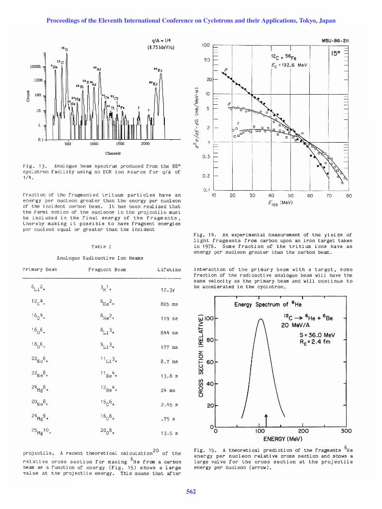
Fig. 12. Analogue beam spectrum produced from a Penning source at the ORIC cyclotron for the mass to charge ratio of 5.
Table 1 lists examples of primary and radioactive analogue beams. The radioactive beam is completely stripped of its electrons as would most probably happen in this energetic collision process. The table indicates that the very light elements and neutron rich radioactive isotopes comprise .the mass region for this method.
Another heavy ion experimental result obtained during the past 10 years is the energy distribution of
the light fragments. 19 For example, Fig. 14 shows the light particle fragment energies from the breakup of a 30 MeV/ll carbon beam. This figure indicates that some
Proceedings of the Eleventh International Conference on Cyclotrons and their Applications, Tokyo, Japan
561
q/A -1/4 MSU-86-211
"0 (8.75 MeV/u) , !2c
10000." 'H. '0A:! .4 Kr
100
12C + 56Fe 15°
50 Ec = 192.6 MeV
p
1000.~ 32 S3' 21SI AI
IOKr 20 -
~ 100 ... 24M,
He. 52Cr 0
t.> \ONe I
10. ~ .. 1'1 i'Pe
~ 10 :> OJ
::> '-..... 5 .c
E
1. ..
I 0. 1
~ I 2
laJ ~ b
sao 1000 1500 2000 N 'tl
Channt13 0 .5
Fig. 13. Analogue beam spectrLUTI produced from the 88 " cyclotron facility using an ECR ion so ur ce for q/A of 1/4. 0 . 2
fraction of the fragmented tri tuum parti cles have an energy per nucleon greater than the energy per nucleon of the incident carbon beam. It has been realized that the Fermi motion of the nucleons in the projectile must be included in the final energy of the fragments, thereby making it possible to have fragment energies per nucleon equal or greater than the incident
Table I
Analogue Radioactive Ion Beams
Primary Beam Fragment Beam Lifetime
6Li 2+ 3H1+ 12.3Y
12C4+ 6He2+ 805 ms
160 4+ 8He2+ 119 ms
1606+ 8L i 3+ 844 ms
1806+ 9Li 3+ 177 ms
22Ne6+ 1 \i 3+ 8.7 ms
22Ne8+ Il Be 4+ 13.8 s
24Mg8+ 12Be 4+ 24 ms
2ONe8+ 15c6+ 2.45 s
24Mg9+ 16c6+ .75 s
25Mg10+ 2°08+ 13.5 s
projectile. A recent theoretical calculation20 of the
relative ~ross section for making 6He from a carbon beam as a function of energy (F ig . 15) shows a large val ue at the proj ectile energy. This means that after
0.1 10 20 30 40 50
Elab (MeV )
60 70 80
Fig. 14. An experimental measurement of the yields of light fragments from carbon upon an iron target taken in 1976. Some fraction of the tritium ions have an energy per nucleon greater than the carbon beam.
interact ion of the primary be am with a target, some fraction of the radioactive analogue beam will have the same velocity as the primary beam and will continue to be accelerated in the cyclotron.
wlOO > ~ ...J W 80 a:
z: 0 ~ 60 u w (f)
(f) 40 (f)
0 a: u
20
00
Energy Spectrum of sHe
12C ---+ sHe + sSe 20 MeV/A
S = 36.0 MeV Rc=2.4 fm
100 200 ENERGY (MeV)
300
Fig. 15. A theoretical prediction of the fragments 6He energy per nucleon relative cross section and shows a large valve for the cross section at the projectile energy per nucleon (arrow).
Proceedings of the Eleventh International Conference on Cyclotrons and their Applications, Tokyo, Japan
562
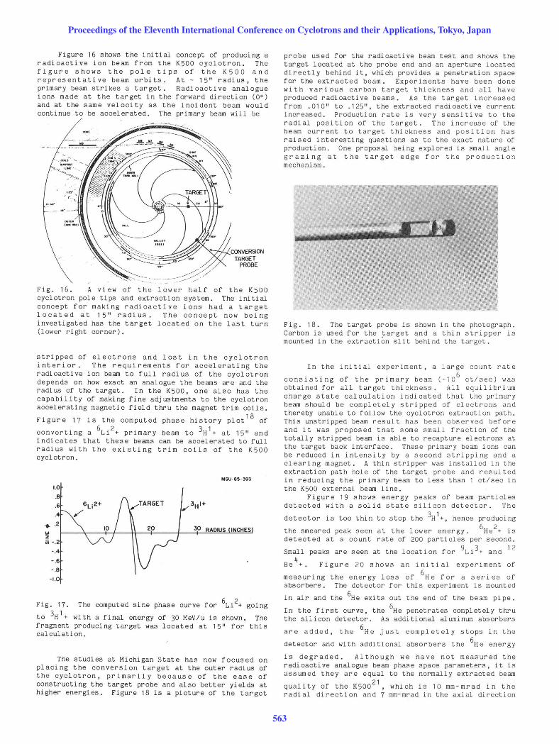
Figure 16 shows the initial concept of producing a radioactive ion beam from the K500 cyclotron. The figure shows the pole tips of the K500 and representative beam orbits. At - 15" radius, the primary beam strikes a target. Radi oacti ve analogue ions made at the target in the forward direction (0 0 )
and at the same velocity as the incident beam would continue to be accelerated. The primary beam will be
/
\
CONVERSION TARGET
PROBE
Fig. 16. A view of the lower half of the K500 cyclotron pole tips and extraction system. The initial concept for making radioactive ions had a target lo cate d at 15" radius. The concept now being investigated has the target located on the last turn (lower right corner).
stripped of electrons and lost in the cyclotron interior. The requirements for accelerating the radioactive ion beam to full radius of the cyclotron depends on how exact an analogue the beams are and the radius of the target. In the K500, one also has the capability of making fine adjustments to the cyclotron accelerating magnetic field thru the magnet trim coils. .. . 18 f F1gure 17 1S the computed phase h1story plot 0
. 6.2. 3 1 convert1ng a L1 + pr1mary beam to H + at 15" and indicates that these beams can be accelerated to full radius with the existing trim co ils of the K500 cyclotron.
1.0
.8
.6
.4
... 2
MSU-85-393
w ~--~~---f-+---4+-~+------r--~~~~~~~~ z 0; -.2
- .4
- .6
-.8
-1.0
Fig. 17. The computed sine phase curve for 6Li 2+ going
to 3H 1 + wi th a final energy of 30 MeV/u is shown. The fragment producing target was located at 15" for this calculation.
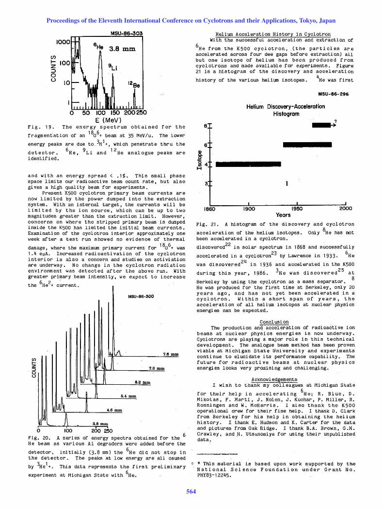
The studies at Michigan State has now focused on placing the conversion target at the outer radius of the cyclotron, primarily because of the ease of constructing the target probe and also better yields at higher energies. Figure 18 is a picture of the target
probe used for the radioactive beam test and shows the t arget located at the probe end and an aperture located directly behind it, which provides a penetration space for the extracted beam. Experiments have been done with various carbon target thickness and all have produced radioactive beams. As the target increased from .010" to .125", the extracted radioactive current increased. Production rate is very sensi ti ve to the radial position of the target. The increase of the beam current to target thickness and position has raised interesting questions as to the exact nature of production. One proposal being explored is small angle grazing at the target edge for the production mechanism.
~
r 7 PS I
Fig. 18. The target probe is shown in the photograph. Carbon is used for the ~arget and a thin stripper i s mounted in the extraction slit behind the target.
In the ini tial experiment, a large count rate
consisting of the primary beam (-10 6 ct/sec) was obtained for all target thickness. All equilibrium charge state calculation indicated that the primary beam should be completely stripped of electrons and thereby unable to follow the cyclotron extraction path. This unstripped beam resul t has been observed before and it was proposed that some smal l fraction of the totally stripped beam is able to recapture electrons at the target back interface. These primary beam ions can be reduced in intensity by a seco nd s tripping and a clearing magnet. A thin stripper was installed in the extraction path hole of the target probe and resulted in reducing the primary beam to less than 1 ct/sec in the K500 external beam line.
Figure 19 shows energy peaks of beam particles detected with a solid state silicon detector. The
detector is too thin to stop the 3Hl+, hence producing
the smeared peak seen at the lower energy . 6He 2+ is detected at a co unt rate of 200 particles per second.
Small peaks are seen at the location for 9Li 3+ and 12
Be 4+. Figure 20 shows an initial experiment of
measuring the energy loss of 6He for a series of absorbers. The detector for this experiment is mounted
in air and the 6He exits out the end of the beam pipe.
In the first curve, the 6He penetrates completely thru the silicon detector. As additional aluminum absorbers
are added, the 6He just completely stops in the
detector and with additi onal absor bers the 6H e ener gy
is degraded. Although we have not measured the radioactive analogue beam phase space parameters, it is assumed they are equal to the normally extracted beam
quality of the K500 21 , which is 10 mm-mrad in the radial direction and 7 mm-mrad in the axial direction
Proceedings of the Eleventh International Conference on Cyclotrons and their Applications, Tokyo, Japan
563
MSU-86-303
1000 6He 3.8 mm (/)
~ 100 z ~ 0 u 10
I
a
Fig. 19. The energy spectrum obtained for the . 18 6 fragmentation of an 0 + beam at 35 MeV/u. The lower
energy peaks are due to . 3H1+, which penetrate thru the 6 9. 12 detector. He, Ll and Be analogue peaks are
identified.
and with an energy spread < .1%. This small phase space limits our radioactive beam count rate, but also gives a high quality beam for experiments.
Present K500 cyclotron primary beam currents are now limited by the power dumped into the extraction system. Wi th an internal target, the currents will be limited by the ion source, which can be up to two magnitudes greater than the extraction limit. However, concerns on where the stripped primary beam is dumped i nsi de the K500 has limi ted the i niti al beam curr ents . Examination of the cyclotron interior approximately one week after a test run showed no evidence of thermal
damage, where the maximum primary current for 1806+ was 1.4 e\1A. Increased radioactivation of the cyclotron interior is also a concern and studies on activiation are underway. No change in the cyclotron radiation environment was detected after the above run. With greater primary beam intensity, we expect to increase
the 6He2+ current
C/) IZ
6 u
o
W\ [~
100
~
MSU-86-300
ldJ\ 7.8 mm
. 7.0 mm
It 8.2 mm
5.4 mm
4.8 mm
3.8 mm
200 250 Fig. 20. A series of energy spectra obtained for the 6 He beam as various Al degraders were added before the
detector. Initially <3.8 mm) the 6He did not stop in the detector. The peaks at low energy are all caused
by 3He1+. This data represents the first preliminary
experiment at Michigan State with 6He •
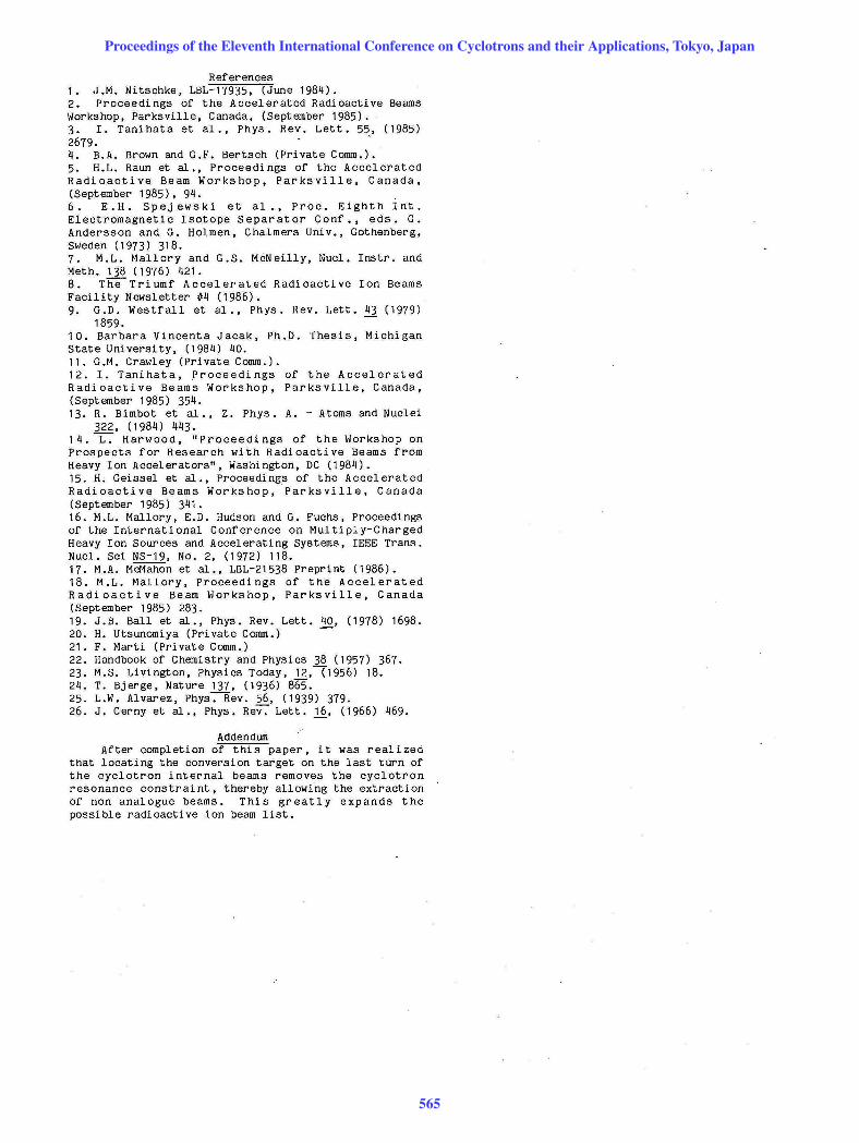
Helium Acceleration History in Cyclotron With the successful acceleration and extraction of
6He from the K500 cyclotron, (the particles are accelerated across four dee gaps before extraction) all but one isotope of helium has been produced from cyclotrons and made available for experiments. Figure 21 is a histogram of the discovery and acceleration
history of the various helium isotopes. 4He was first
8
MSU-86-296
Helium Discovery-Acceleration Histogram
7 )
1860 1900 1950 Years
2000
Fig. 21. A histogram of the discovery and cyclotron
acceleration of the helium isotopes. Only 8He has not been accelerated in a cyclotron.
discovered22 in solar spectrum in 1868 and successfully
accelerated in a CYClotron23 by Lawrence in 1933. 6He
was discovered24 in 1936 and accelerated in the K500
during this year, 1986. 3He was discovered 25 at
Berkeley by using the cyclotron as a mass separator. 8
He was produced for the first time at Berkeley, only 20 years ago, and has not yet been accelerated in a cyclotron. Within a short span of years, the acceleration of all helium isotopes at nuclear physics energies can be expected.
Conclusion The production and acceleration of radioactive ion
beams at nuclear physics energies is now underway. Cyclotrons are playing a major role in this technical development. The analogue beam method has been proven viable at Michigan State Uni versi ty and experiments continue to elucidate its performance capability. The future for radioactive beams at nuclear physics energies looks very promising and challenging .
Acknowledgements I wish to thank my colleagues at Michigan State
for their help in accelerating 6He ; R. Blue, D. Mikolas, F. Marti, J. Nolen, J. Kuchar, P. Miller, R. Ronningen and W. McHarris. I also thank the K500 operational crew for their fine help. I thank D. Clark from Berkeley for his help in obtaining the helium history. I thank E.. Hudson and K. Carter for the data and pictures from Oak Ridge. I thank B.A. Brown, G.M. Crawley, andH. Utsunomiya for using their unpublished data.
~, * This material is based upon work supported by the National Science Foundation under Grant No. PHY83-12245.
Proceedings of the Eleventh International Conference on Cyclotrons and their Applications, Tokyo, Japan
564
References 1. J .M. Nitschke, LBL-17935, (June 1984). 2. Proceedings of the Accelerated Radioactive Beams Workshop, Parksville, Canada, (September 1985). 3. 1. Tanihata et al., Phys. Rev. Lett. 55, (1985) 2679. . 4. B.A. Brown and G.F. Bertsch (Private Comm.). 5. H.L. Raun et al., Proceedi ngs of the Accelerated Radioactive Beam Workshop, Parksville, Canada, (September 1985), 94. 6. E.H. Spejewski et al., Proc. Eighth Int. Electromagnetic Isotope Separator Conf., eds. G. Andersson and G. Holmen, Chalmers Univ., Gothenberg, Sweden (1973) 318. 7. M.L. Mallory and G.S. McNeilly, Nucl. Instr. and Meth. 138 (1976) 421. 8. TheTriumf Accelerated Radioactive Ion Beams Facility Newsletter #4 (1986). 9. G.D. Westfall et al., Phys. Rev. Lett. 43 (1979)
1859. 10. Barbara Vincenta Jacak, Ph.D. Thesis, Michigan State University, (1984) 40. 11. G.M. Crawley (Private Comm.). 12. I. Tanihata, Proceedings of the Accelerated Radioactive Beams Workshop, Parksville, Canada, (September 1985) 354. 13. R. Bimbot et al., Z. Phys. A. - Atoms and Nuclei
322, (1984) 443. 14. L. Harwood, "Proceedings of the Workshop on Prospects for Research with Radioactive Beams from Heavy Ion Accelerators", Washington, DC (1984). 15. H. Geissel et al., Proceedings of the Accelerated Radioactive Beams Workshop, Parksville, Canada (September 1985) 341. 16. M.L. Mallory, E.D. Hudson and G. Fuchs, Proceedings of the International Conference on Multiply-Charged Heavy Ion Sources and Accelerating Systems, IEEE Trans. Nucl. Sci NS-19, No.2, (1972) 118. 17. M.A. McMahon et al., LBL-21538 Preprint (1986). 18. M.L. Mallory, Proceedings of the Accelerated Radioactive Beam Workshop, Parksville, Canada (September 1985) 283. 19. J.B. Ball et al., Phys. Rev. Lett. 40, (1978) 1698. 20. H. Utsunomiya (Private Comm.) 21. F. Marti (Private Comm.) 22. Handbook of Chemistry and Physics 38 (1957) 367. 23. M.S. Livington, Physics Today, 12,-r1956) 18. 24. T. Bjerge, Nature 137, (1936) 865. 25. L.W. Alvarez, Phys~ev. 56, (1939) 379. 26. J. Cerny et al., Phys. Re~ Lett. 1£, (1966) 469.
Addendum After completion of thi s paper, it was real i zed
that locating the conversion target on the last turn of the cyclotron internal beams removes the cyclotron resonance constraint, thereby allowing the extraction of non analogue beams. This greatly expands the possible radioactive ion beam list.
Proceedings of the Eleventh International Conference on Cyclotrons and their Applications, Tokyo, Japan
565