Embed Size (px)
Citation preview
Proceedings of the 2018 Manufacturing Science and Engineering Conference MSEC2018
June 18-22, 2018, College Station, TX, USA
MODELING OF TOOL-WORKPIECE INTERACTION IN A VOXELIZED FRAMEWORK
John C. Miers Georgia Institute of Technology
Atlanta, GA, USA
Tommy Tucker Tucker Innovations, Inc.
Charlotte, NC, USA
Thomas Kurfess Georgia Institute of
Technology Atlanta, GA, USA
Christopher Saldana Georgia Institute of
Technology Atlanta, GA, USA
ABSTRACT In the present study, a voxel based model for the
interaction between cutting teeth of an arbitrary end mill geometry and a workpiece is presented. In this framework, the workpiece geometry is modeled using a voxelized representation that is dynamically updated as material is locally removed by each tooth of the cutting tool. A ray casting approach is used to mimic the process of the rake face of a tool moving through the workpiece material and to calculate the undeformed chip thickness and its variation in time. The resulting voxel based model framework was validated by comparison of predictions with experimentally measured milling forces. The results demonstrate the model’s ability to accurately simulate the interaction of cutting teeth with the bulk material of the workpiece. Implications of this new voxel based model framework are briefly discussed in terms of utility for predicting local surface finish and computational scalability of complex cutting configurations.
INTRODUCTION The object of the current research is to develop a
generalized voxelized model for the interaction of an arbitrary milling cutter with a body of material being machined, independent of specialized analytical solutions for individual scenarios. This model, which connects the motion of the cutting geometry of a given end mill directly to the material removal from the part, will provide information about the current geometry of the part and facilitate prediction of material removal and machining forces for arbitrary freeform tool paths. The purpose is to address the growing needs of various industries such as the aerospace, automotive, mold/die, and telecommunications industries for high fidelity, complex, and freeform parts, this coalescing with the imperative need of increased production rates. Without a proper understanding of the interaction between the tool and the feature being produced, conservative machine parameters are used, limiting process efficiency. It is precisely for this reason that there has been so much analysis of the milling process over the last half-century.
As far back as 1941, the mechanics of the milling process have been studied to mathematically evaluate the effect of specific cutting parameters on the resultant part quality [3]. Excellent summations of work completed in this field over the last 60+ years can be found in [4] [5] [6] [7]. It is sufficive to say that many of these studies have focused on the prediction of the instantaneous forces resulting from the tool ploughing and shearing through the material as it cuts [8]. Definition of cutting forces, acting on the cutting edge of a tool, from the application of empirical cutting force coefficients and chip area is at the root of mechanistic process models [9]. In the early 2000s, models began to focus on using finite element (FE) and other numerical methods for this predictive modelling of forces, and most recently there has been a major drive to model individual tools and tool types with greater accuracy [10] [11] [12] [13].
While unified cutting force models for many different tool geometries exist and the modelling of tool geometries is well defined [9], surprisingly little research has been done in the interaction of the tool with a complex workpiece consisting of a distributed or complex contact with a part geometry. An excellent review of the current models for tool-workpiece interaction is given in Ref. [14]. A primary reason for this state, is the complexity of analytical expressions that are required to simulate cutter envelopes and intersections of constructive solid geometries in time, much less for predicting the manner in which the cutting tooth has engaged in the bulk of the material. The computational expense of this problem is less of an issue with modern computer hardware, but the large amount of prior knowledge that is required to simulate such scenarios still pushes them beyond pragmatic application.
Due to the improvements in specialized computing hardware for graphics processing, the goal of simulating the interaction between a workpiece and a given tool is attainable in a discrete fashion. Leveraging the parallel processing power of multi-core CPU and general-purpose graphics processing units (GPGPU), voxel based simulation of the interaction of a discrete workpiece and an arbitrary tool is possible. The use of voxel modelling for path planning in automated 5-axis machine tool paths has
already been established [15] [16]. Fitting with the trend in digital manufacturing, a model of tool-workpiece interaction based on a voxel framework can co-opt robust computer graphics processes for accelerating computation in this significant area of opportunity.
In this paper, a voxel based model for describing the interaction between an arbitrary end mill geometry with a given workpiece will be developed and validated against experimental milling force data. To this end, the simulation of a simplified slot cutting operation will be performed for a case without cutter deflection. The added benefit of simultaneous calculation of intermediate workpiece geometry will be briefly discussed in the context of a complex machining configuration employing subsequent tool passes. The organization of this paper henceforth is outlined in the following: (1) methods for modelling the components and combined result of the tool and workpiece interaction are detailed, (2) results of the prediction of milling forces are presented and further analyzed, (3) conclusions and summation of this proposed approach are drawn.
TOOL-WORKPIECE INTERACTION MODEL In this section, elements of the proposed method are
described followed by description of their integration to simulate the physical interaction of the milling tool and part system.
Workpiece Model The digitization of the workpiece into discrete
volumes is accomplished through a process of voxelization. A voxel is a cubic volume element with equal side lengths or isotropic voxel size. Voxels can be represented by values in three-dimensional space on a conventional grid, just as pixels are represented by values on a two-dimensional grid in two-dimensional space. Voxelization allows for improved computational speed over conventional approaches using constructive solid geometry (CSG) because pre-allocation of space yields well to an integer data structure rather than the highly accurate, but computationally expensive floating point data structure required for conventional CSG. A flowchart of the high-level algorithm used in this model is shown in Figure 1.
As voxel size becomes infinitely small, the voxelized representation approaches the ideal representation of the physical workpiece as a continuous medium. However, the workpiece representation must be computationally efficient; therefore, a sufficiently small voxel size must be determined. Traditionally, the description of parts through volumetric data has been impractical due to limitations in computer memory; however, modern computing hardware enable the use of dense volumetric representations instead of only surface interpretations [15]. As three-dimensional volume elements are analogous to two-dimensional pixels, voxel based data structures yield well to graphics processing hardware and techniques [16]. For this research, the voxelized workpiece is represented with a three-dimensional binary data structure to reduce the memory requirements. Consequently, only seven other scalar values are needed to completely describe the workpiece space. Six values describe the minimum and maximum bounds of the three-dimensional array and the last value is the voxel size, which represents the characteristic length of the system.
Tool Model With a sufficiently small voxel size, the physical
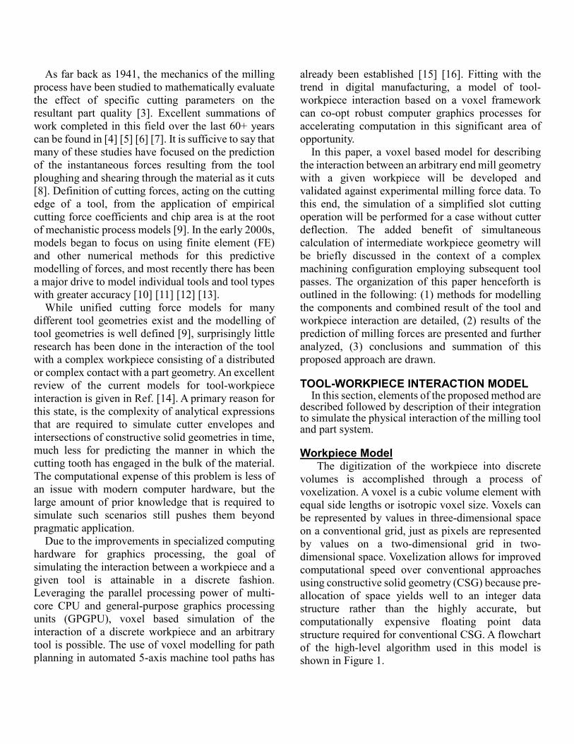
process of a cutting flute passing through a material during the machining process is emulated by using a tool model to remove the voxels as they come into contact with the helical flute of the cutting tool model. An overview of a typical tool workpiece interaction is shown in Figure 2. To reduce computational load,
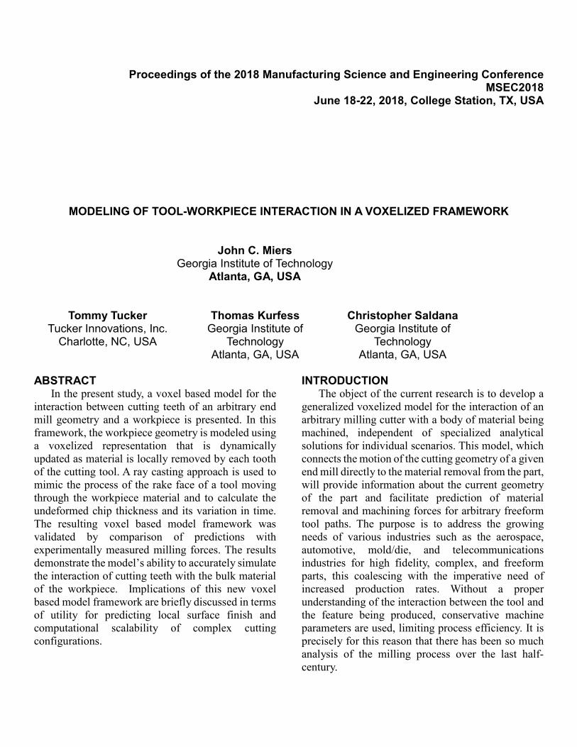
only the necessary parts of the cutter geometry are modeled; however, to calculate the tool-workpiece interaction accurate representation of the necessary tool geometry is needed. The instantaneous motion of the flute of a cutter moving through the medium of the workpiece is often represented as an oblique or orthogonal cutting process [17]. As can be seen in Figure 3, the majority of the contact is on the cutting edge and rake of a cutting flute. The helical cutting edge of the tool, the outermost edge of the tool, is assumed to be the only part of the tool in contact with the final surface of the machined workpiece. Accordingly, by approximating the cutting edge of the tool to be infinitely sharp the tool can be modelled with the rake face starting from the cutting edge. This differs from the enveloped surface tool models used by most modern CAM software [18]. Models for the combination of the cutter envelope and outermost edge of the helical flutes have been developed [10], but these fail to account for the remaining rake face geometry. In the present approach, tools are modelled with lines representing the location of the rake face at a given step along the flute of the cutter and at a specific point in time. These lines extend from points distributed along the cutting edge, along the surface
Figure 2 - Example of the tool model interaction with a voxelized workpiece for a 2-flute ball end mill.
Figure 1 - Two-dimensional illustration of an up-milling operation along an arbitrary feed direction, where WCS is the world coordinate system and TCA is the tool coordinate system.
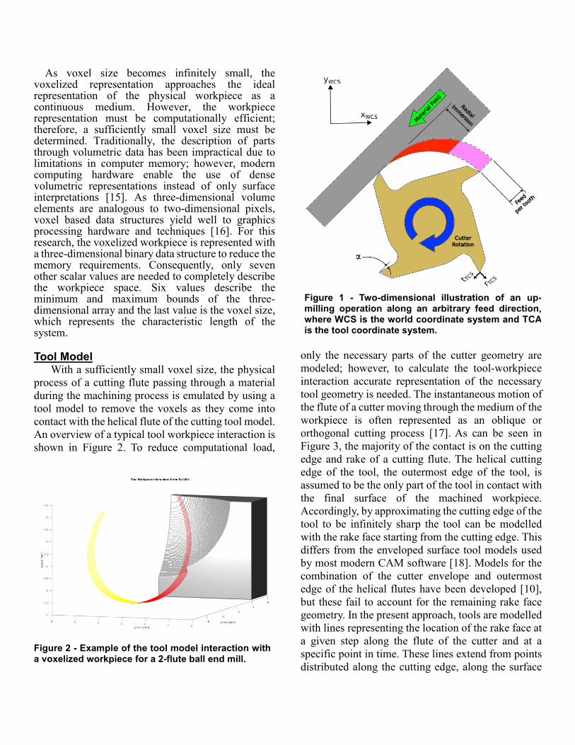
of the face and in a plane that is perpendicular to the axis of the tool rotation. An exaggerated example of points distributed along a cutting edge of the tool and the subsequent rake lines that extend from them is shown is Figure 4. For the representation of the end geometry of an arbitrary mill, the notation used by Childs [19] was adopted. The calculation of tool geometry in this model requires less prior knowledge of the tool parameters than the work by Engin and Altintas [10]; however, when generating mills with any radii in the end geometry only continuous flute curvatures are capable of being generated. The trochoidal motion of the flutes in a physical tool are represented by discrete translations along the feed direction and rotations about its cylindrical axis simultaneously to pragmatically decompose the trochoidal path into discrete time steps.
Tool-Workpiece Interaction Model This method is largely dependent on the approach
to simulating the tool and workpiece interaction. The approach utilized in this research is the representation of the workpiece with a volumetrically digitized space and the discretization of the temporal motion of the tool. As the tool is fed forward and rotates about its axis, the rake lines will move into contact with different voxels. As these voxels are contacted, their representative value is changed from one to zero, this effectively simulating their removal from the workpiece. The process of calculating the intersections of the rake lines with voxels is performed with a ray casting algorithm.
As an elegant method for rendering images, ray casting is amply used in both computer generated images (CGI) and video games. Due to the extensive industrial activity in these areas, developments in ray casting have been significant in recent decades, including developments in graphics processing unit hardware specifically able to accelerate 3D rendering [20]. Ray casting approaches can be broken down into two main groups: continuous and discrete [21]. While continuous algorithms may be easier to understand, as they are essentially based on the parametric equation for a line, the computational load required to implement them is significantly higher than discrete methods. In comparison, discrete algorithms pre-allocate the memory needed via the subdivision of space into elements such as voxels.
In typical ray casting implementation, four primary steps are followed: (1) a ray of light is projected from a given view, (2) the ray is sampled along its length
for objects pierced by the straight line, (3) shading due to a distant source of light is calculated, (4) the objects are assembled along the ray back to the source to determine what is displayed at that location in the image [22]. In the proposed method, the rake lines of the tool model are used as the rays in the algorithm for ray tracing. Since the ray casting is being used as a method of detecting the interaction between the tool and the workpiece, no rendering steps are needed. The discrete ray casting approach used in this model is based on the traversal algorithm developed by John Amanatides and Andrew Woo in 1987 [23]. The traversal of the ray is performed by stepping from voxel to voxel in the direction of the smallest distance the ray would need to travel to reach the next voxel boundary.
Using a modification of this algorithm, the voxels that are intersected by the rake lines are calculated by looping through the motion of the tool over time. Voxels are removed from the blank by setting their value to false, which indicates that they cannot be removed again. The number of voxels removed by a rake line in each of the primary directions of the voxelized array are used to calculate the distance through the material that the rake face of the tool would travel. This value is stored as the uncut chip
Figure 4 - Section view of a 4-flute helical cutter. Examples of rake line placement are show visually by the red lines extending along the rake face of one flute. The differential elements of the cutting force are shown at the end of each rake line to represent the role rake lines have in determining the cutting force calculated later in this paper.
thickness of the process and later used in the calculation of machining forces. The process is summarized in the following pseudo code.
for a step in time for a given flute j for a line along the rake face while on the line step to next closest voxel along the rake line end while h = sqrt(Nx^2+Ny^2+Nz^2)*vs end for end for end for
Milling Force Model The voxel based force model used implements the
derivation of milling forces from orthogonal cutting data by Budak et al. in 1996 [17]. Calculation of the milling forces in a voxelized framework requires only a slight modification of the published equations of milling forces in the tool coordinate system into the following form:
𝑑𝑑𝐹𝐹𝑇𝑇,𝑗𝑗,𝑃𝑃(𝑡𝑡) = 𝐾𝐾𝑇𝑇𝑇𝑇𝑑𝑑𝑑𝑑 + 𝐾𝐾𝑇𝑇𝑇𝑇ℎ𝑗𝑗,𝑃𝑃(𝑡𝑡)𝑠𝑠𝑣𝑣𝑣𝑣𝑑𝑑𝐹𝐹𝑅𝑅,𝑗𝑗,𝑃𝑃(𝑡𝑡) = 𝐾𝐾𝑅𝑅𝑇𝑇𝑑𝑑𝑑𝑑 + 𝐾𝐾𝑅𝑅𝑇𝑇ℎ𝑗𝑗,𝑃𝑃(𝑡𝑡)𝑠𝑠𝑣𝑣𝑣𝑣𝑑𝑑𝐹𝐹𝐴𝐴,𝑗𝑗,𝑃𝑃(𝑡𝑡) = 𝐾𝐾𝐴𝐴𝑇𝑇𝑑𝑑𝑑𝑑 + 𝐾𝐾𝐴𝐴𝑇𝑇ℎ𝑗𝑗,𝑃𝑃(𝑡𝑡)𝑠𝑠𝑣𝑣𝑣𝑣
(1)
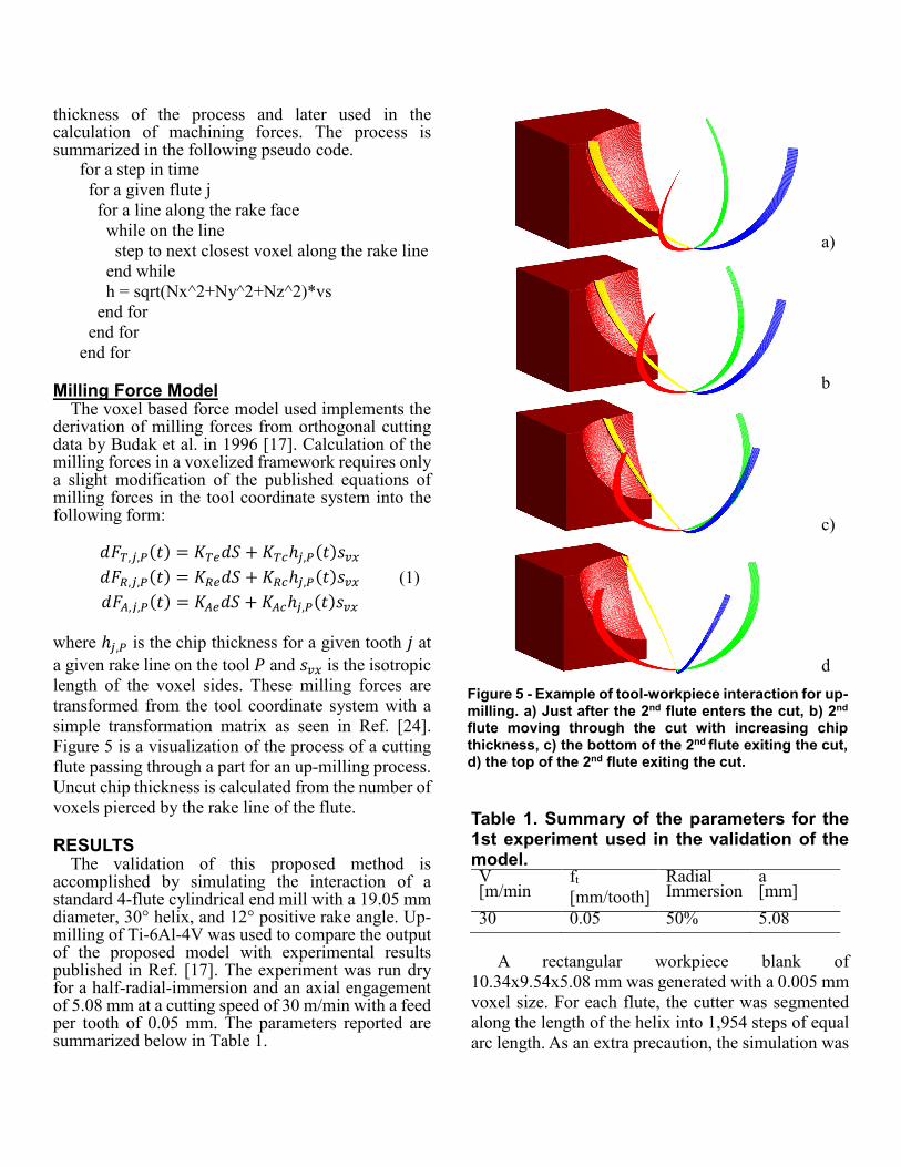
where ℎ𝑗𝑗,𝑃𝑃 is the chip thickness for a given tooth 𝑗𝑗 at a given rake line on the tool 𝑃𝑃 and 𝑠𝑠𝑣𝑣𝑣𝑣 is the isotropic length of the voxel sides. These milling forces are transformed from the tool coordinate system with a simple transformation matrix as seen in Ref. [24]. Figure 5 is a visualization of the process of a cutting flute passing through a part for an up-milling process. Uncut chip thickness is calculated from the number of voxels pierced by the rake line of the flute.
RESULTS The validation of this proposed method is
accomplished by simulating the interaction of a standard 4-flute cylindrical end mill with a 19.05 mm diameter, 30° helix, and 12° positive rake angle. Up-milling of Ti-6Al-4V was used to compare the output of the proposed model with experimental results published in Ref. [17]. The experiment was run dry for a half-radial-immersion and an axial engagement of 5.08 mm at a cutting speed of 30 m/min with a feed per tooth of 0.05 mm. The parameters reported are summarized below in Table 1.
Table 1. Summary of the parameters for the 1st experiment used in the validation of the model. V [m/min
ft [mm/tooth]
Radial Immersion
a [mm]
30 0.05 50% 5.08
A rectangular workpiece blank of 10.34x9.54x5.08 mm was generated with a 0.005 mm voxel size. For each flute, the cutter was segmented along the length of the helix into 1,954 steps of equal arc length. As an extra precaution, the simulation was
a)
c)
d)
b)
Figure 5 - Example of tool-workpiece interaction for up-milling. a) Just after the 2nd flute enters the cut, b) 2nd
flute moving through the cut with increasing chip thickness, c) the bottom of the 2nd flute exiting the cut, d) the top of the 2nd flute exiting the cut.
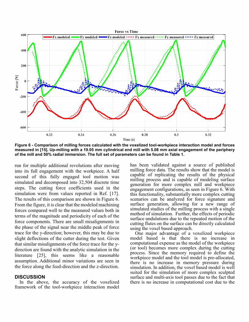
run for multiple additional revolutions after moving into its full engagement with the workpiece. A half second of this fully engaged tool motion was simulated and decomposed into 32,504 discrete time steps. The cutting force coefficients used in the simulation were from values reported in Ref. [17]. The results of this comparison are shown in Figure 6. From the figure, it is clear that the modeled machining forces compared well to the measured values both in terms of the magnitude and periodicity of each of the force components. There are small misalignments in the phase of the signal near the middle peak of force trace for the y-direction; however, this may be due to slight deflections of the cutter during the test. Given that similar misalignments of the force trace for the y-direction are found with the analytic simulation in the literature [25], this seems like a reasonable assumption. Additional minor variations are seen in the force along the feed-direction and the z-direction.
DISCUSSION In the above, the accuracy of the voxelized
framework of the tool-workpiece interaction model
has been validated against a source of published milling force data. The results show that the model is capable of replicating the results of the physical milling process and is capable of modeling surface generation for more complex mill and workpiece engagement configurations, as seen in Figure 6. With this functionality, substantially more complex cutting scenarios can be analyzed for force signature and surface generation, allowing for a new range of simulated studies of the milling process with a single method of simulation. Further, the effects of periodic surface undulations due to the repeated motion of the cutting flutes on the surface can be directly calculated using the voxel based approach.
One major advantage of a voxelized workpiece model based is that there is no increase in computational expense as the model of the workpiece (or tool) becomes more complex during the cutting process. Since the memory required to define the workpiece model and the tool model is pre-allocated, there is no increase in memory pressure during simulation. In addition, the voxel based model is well suited for the simulation of more complex sculpted surface and multi-axis tool passes due to the fact that there is no increase in computational cost due to the
Figure 6 - Comparison of milling forces calculated with the voxelized tool-workpiece interaction model and forces measured in [15]. Up-milling with a 19.05 mm cylindrical end mill with 5.08 mm axial engagement of the periphery of the mill and 50% radial immersion. The full set of parameters can be found in Table 1.
interaction being carried out by ray casting through a voxelized framework [20].
A potential limitation of the approach is that since the root of this simulation is a voxelized framework, the effect of voxel size on the output of the tool-workpiece interaction model is multi-fold. First, in terms of the tool model, the steps along the arc of the helical flute and the forward step of the tool along the feed direction must be less than or equal to the voxel size. Moreover, the overall time step of the tool must be linked to the voxel size such that motion of the outermost point of the tool is less than a voxel size. Without enforcing this condition, it would not be possible to ensure that voxels will be removed in the discrete stepping of the flute along its trochoidal path. Additionally, to obtain accurate data pertaining to a given feature of the milling process, the voxel size must be smaller than the desired tolerance of the study. This critical condition becomes especially important for accurately accounting for the forces experienced in the milling process in terms of feed per tooth in relation to voxel size. This condition can also be important for determining residual geometric features on the work surface, such as scallop height.
Ongoing efforts are establishing the tradeoffs of the voxel based approach relative to the benefits of ease of use and ability to handle increasing workpiece and cut complexity without increasing computational cost. Of particular interest are scale-dependent limits of representation of smooth continuous phenomena such as force traces, which can become subject to computational noise do to the discrete volume structure. Additionally, efforts are underway to determine critical relationships between minimum feature size, model voxel size and simulation fidelity.
CONLCULSIONS In the present study, a model for simulating the
interaction between the tool and the workpiece was proposed. The voxel based simulation method was validated against experimentally measured milling force data. Further functionalities of the model were discussed, including the ability to eliminate the need for specialized analytical calculations of chip thickness for complex milling operations and the ability to predict part geometry resulting from specific tool motions. The voxel based simulation method provides a useful and highly parallelizable tool for visualizing and calculating the effects for arbitrary end mill and workpiece engagements, this enabling
integration within complex, self-optimizing, multi-axis path planning methods.
ACKNOWLEDGMENTS This work was supported by NSF grants IIP
1631803 and CMMI 1646013.
REFERENCES [1] M. E. Martellotti, "An Analysis of the Milling
Process," Transactions of the A.S.M.E., vol. 63, no. 8, pp. 677-700, November 1941.
[2] K. F. Ehmann, S. G. Kapoor, R. E. DeVor and I. Lazoglu, "Machining Procces Modelling: a Review," Journal of Manufacturing Science and Engineering, vol. 119, no. 1997, pp. 655-663, November 1997.
[3] G. Quintana and J. Ciurana, "Chatter in Machining Porcesses: A Review," International Journal of Machine Tools and Manufacture, vol. 51, no. 2011, pp. 363-376, 2011.
[4] P. G. Benerdos and G. Vosniakos, "Predicting Surface Roughness in Machining: A Review," The International Journal of Maching Tools and Manufacture, vol. 43, no. 2003, pp. 833-844, 2003.
[5] J. C. Miao, G. L. Chen, X. M. Lai, H. T. Li and C. F. Li, "Review of Dynamic Issures in Micro-End-Milling," International Journal of Advanced Manufacturing Technology, vol. 31, no. 2007, pp. 897-904, 2005.
[6] M. Wan, W.-H. Zhang, J.-W. Dang and Y. Yang, "A Novel Cutting Force Modelling Method for Cylindrical End Mill," Applied Mathematical Modelling, vol. 34, no. 2010, pp. 823-836, 2008.
[7] M. Kaymakci, Z. M. Kilic and Y. Altintas, "Unified Cutting Force Model for Turning, Boring, Drilling and Milling Operations," International Journal of Machine Tools and Manufacture, Vols. 54-55, no. 2012, pp. 34-45, December 2011.
[8] S. Engin and Y. Altintas, "Mechanics and Dynamics of General Milling Cutters. Part 1: Helical End Mills," International Journal of Machine tools and Manufacture, vol. 41, pp. 2196-2212, 2001.
[9] I. Lazoglu, "Sculpture Surface Machining: A Generalized Model of Ball-End Milling Force System," International Journal of Machine Tools and Manufacture, vol. 43, no. 2003, pp. 453-462, 29 November 2002.
[10] A. Azeem, H.-Y. Feng and L. Wang, "Simplified and Efficient Calibration of a Mechanistic Cutting Force Model for Ball-End Milling," International Journal of Machine Tools and Manufacture, vol. 44, no. 2004, pp. 291-298, 25 September 2003.
[11] L. Zhang, L. Zheng, Z.-H. Zhang, Y. Liu and Z.-Z. Li, "On Cutting Forces in Peripheral Milling of Curved Surfaces," Journal of Engineering Manufacture, vol. 216, no. 10, pp. 1385-1398, 2002.
[12] S. D. Merdol and Y. Altintas, "Virtual Simulation and Optimization of Milling Operations-Part 1: Process Simulation," Journal of Manufacturing Science and Engineering, vol. 130, no. 051004, pp. 1-12, October 2008.
[13] J. Tarbutton, T. R. Kurfess, T. Tucker and D. Konobrytskyi, "Gouge-Free Voxel Based Machining for Parallel Processors," International Journal of Advance Manufacturing Technology, vol. 69, no. 2013, pp. 1941-1953, 13 July 2013.
[14] J. A. Tarbutton, T. R. Kurfess and T. M. Tucker, "Graphics Based Path Planning for Multi-Axis Machine Tools," Computer Aided Design and Applicatoins, vol. 7, pp. 835-845, 2008.
[15] E. Budak, Y. Altintas and E. J. A. Armarego, "Prediction of Milling Force Coefficients from Orthogonal Cutting Data," Journal of Manufacturing Science and Engineering, vol. 118, no. May 1996, pp. 216-224, July 1994.
[16] O. Y. Jazi, "Prediction of Cutting Force in 3-Axis CNC Machines Based on a Voxelization Framework for Digital Manufacturing," in Procedia Manufacturing: 43rd Proceedings of the North American Manufacturing Research Institution of SME, 2015.
[17] J. C. James, Numerical Control Part Programming, Industrial Press, 1973.
[18] S. J. Wou, Y. C. Shin and H. El-Mounayri, "Ball End Milling Mechanistic Model Based on a Voxel-Based Geometric Reresentation and a Ray Casting Technique," Journal of Manufacturing Processes, vol. 15, 2013.
[19] B. Zalik, G. Clapworthy and C. Oblonsek, "An Efficient Code-Based Voxel-Traversing Algorithm," Computer Graphics Forum: The Eurographics Association, vol. 16, no. 2, pp. 119-128, 1997.
[20] J. Pawasauskas, "Volume Visualization with Ray Casting," 18 February 1997. [Online]. Available: http://web.cs.wpi.edu/~matt/courses/cs563/talks/powwie/p1/ray-cast.htm#Introduction. [Accessed 21 October 2017].
[21] J. Amanatides and A. Woo, "A Fast Voxel Traversal Algorithm for Ray Tracing," Proceedings in Eurographics, pp. 1-10, 1987.
[22] K. Zhu and Y. Zhang, "Modeling of the Instantaneous Milling Force per Tooth without Tool Run-Out Effect in High Speed Ball-End Milling," International Journal of Machine Tools and Manufacture, Vols. 118-119, pp. 37-48, 2017.
[23] Y. Altintas, Manufacturing Automation, Cambridge: The Press Syndicate of the University of Cambridge, 2000, pp. 4-47.