Embed Size (px)
Citation preview
DEVELOPMENT OF THE VACUUM SYSTEM FOR ATF DAMPING RING
Nobuhiro Terunuma, Masaki Tejima, Junji Urakawa, Fujio Hinode KEK, National Laboratory for High Energy Physics
1-1 Oho, Tsukuba-shi, Ibaraki-ken 305, Japan
Abstract
Design study on the vacuum system for the damping ring of the Accelerator Test Facility (ATF) is now in progress. It must be designed to achieve a pressure that does not cause the unacceptable emittance growth through the beam-gas scattering. Further, it has to get low impedance to suppress single bunch instabilities. Vacuum chambers for an arc section have already been fabricated. These chambers have no photon ma~ks and keep its circular cro~s section. The NEG strips are planned to install in the wiggler chamber. Optimized its ~upports were tested during the activation of the strip.
Introduction
The damping ring of the ATF is a race-track type that is dc~igned to achieye the vertical emittance of 10-11 radm. (1.54 Ge V. 600 rnA and 138.6 m). To get the good damping performance of the ring. the length of the drift space between a magnet and neighboring one is minimized. For a dipole and a quadrupole. it is 100 mm lon g including a coil space. Therefore. bellows. flanges and beam position monitors have to be I<)cated in this short distance.
Moreover, the hard-intense synchrotron radiation (SR) is an import ant issue for the vacuum system. It is produced by using com hi ned-type dipoles in arc sections and mUltipole wigglers in straigh t sections. It causes a wall heating of vacuum chambers and a heavy gas load that determines the operat ing pressure of the ring. The maximum power density at the chamber wall will reach 1.4 and 1.7 kW 1m for the downstream of the dipole magnet and the wiggler magnet. re~pectively . These power loads should be rcmoycd by using the water-cooling system.
In the vacuum chamber, a scattering ofa beam with residual ga~es leads to the emittance growth of the beam [I]. Therefore, the pressure must be low enough to put down this effect. Allowing this kind of the emittance growt h as 10 % of the designed one. an aimed average pressure of the ring is obtained as below 5x 10⁻⁸ Torr.
Vacuum Chambers
Most of vacuum chambers are made of aluminum alloy (A6063). because it is easy to extrude with a thin thickness and a complicated cross section. Further, it has good thermal conductivity as compared with the stainless steel. In the extrusi on process. chambers are filled with the mixture gas of Ar and 02 to keep the surface clean [2]. Bending of the dipole chamber is performed using the stre tch forming process. All extruded chamhers are machined using the EL-process [3] and arc welded together by the method of the TIG welding and the electron beam welding. Completed chambers are scaled and filled with dry nitrogen for storage. Before the assembly in the ring, they will be baked up to 150°C for 24 hours.
Arc Sections
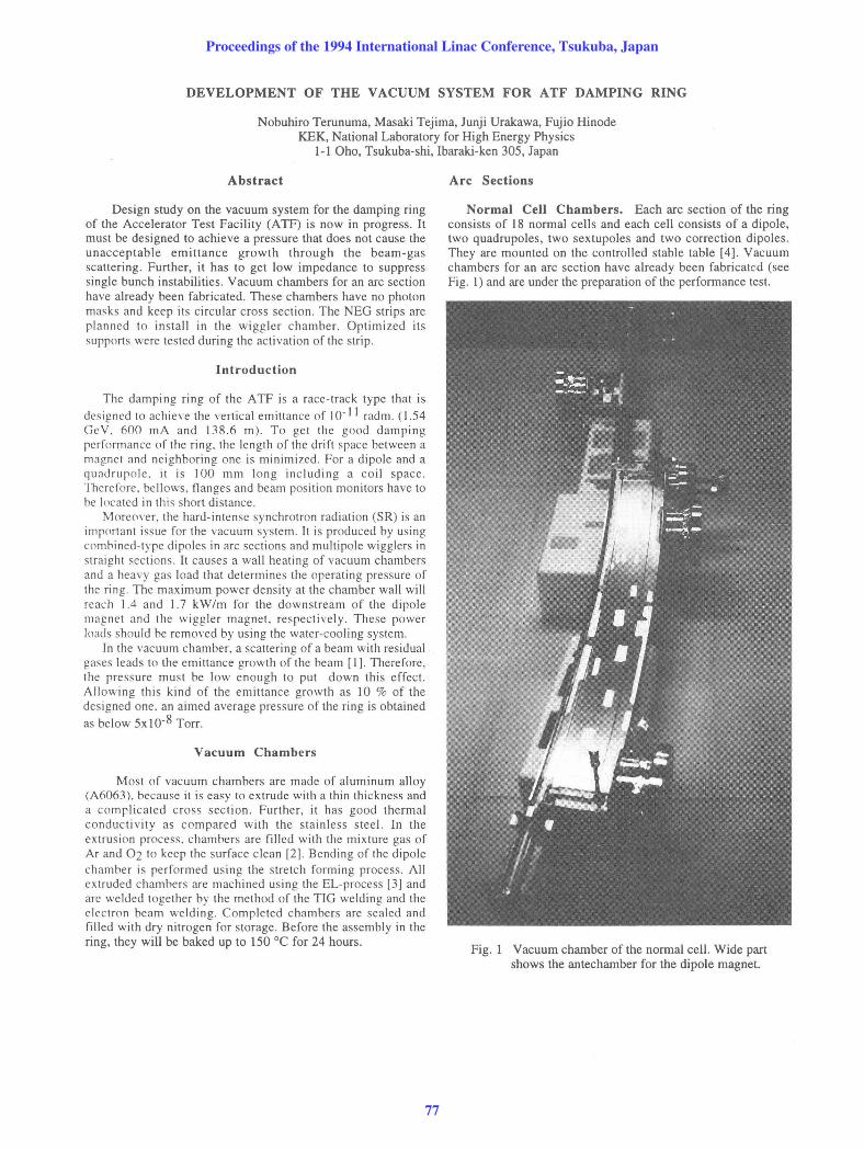
Normal Cell Chambers. Each arc section of the ring consists of 18 normal cells and each cell consists of a dipole, two quadrupoles, two sextupo!es and two correction dipoles. They are mounted on the controlled stable table [4]. Vacuum chambers for an arc section have already been fabricated (see Fig. I) and are under the preparation of the performance test.
Fig. 1 Vacuum chamber of the normal cell. Wide part shows the antechamber for the dipole magnet.
Proceedings of the 1994 International Linac Conference, Tsukuba, Japan
77

The length of a nonnal cell is 2.42 meter and the effective length of a dipole part is one meter. Basic cross section of the extruded aluminum alloy for these chambers (see Fig. 2) is a circle of 24 mm inner diameter.
Fig. 2 Cross section of the extruded aluminum alloy for the nonnal cell chamber. Circular one is for the straight part and antechamber is for the dipole part.
Further, antechamber is adopted to the dipole chamber, because the pole gap of the dipole magnet is opened to the outer side of the ring. Bending radius oJ this chamber is 5.73 meter. This structure has some advantages. Conductance between the beam channel and the pumping port is enough to achieve the aimed pressure . It does not require the manufacturing of many pumping slots . The gas-desorption region induced by SR light is localized to the lower desorption region , such as SR absorber.
Both extruded chambers are welded to keep the step of the beam-channel surface below 0.1 mm. In particular, the vacuum chamber is designed to have no photon masks in the arc section . As a result, the cross section of the beam channel is kept over 43 meter length (one arc section).
Absorbers. At the end of the antechamber, the photon absorber is mounted with the con flat flange. It is made of OFC tube to cool down the heat induced by the SR power of 980 Watts. The maximum temperature estimated by the finite clement method becomes 120 °C. Further, the gas desorption induced by SR is lower for copper than for aluminum.
BPMs. Two beam position monitors (button type) are located in a normal cell. One is fixed to the quadrupole, while the other is located between the dipole and the sextupole with a support system. Its support head can slide along the beam axis to release the extension stress of the chamber. Four pickup electrodes with SMA-type feed through are welded on the alignment base machined from an aluminum block (see Fig . 3). In this process, an electron beam welding is adopted to minimize the welding stress. Each electrode disc is 12 mm diameter and is fonned to keep the cross section of the beam channel.
Pumping Scheme. Three pumping ports with con flat flanges are welded on the chamber. They are used to connect ion pumps, cartridge-type NEG pumps, pressure gauges and right-angle valves for roughing pump systems.
Pumps that have an effective pumping speed of 60 I/s or more will be prepared for beam operation.
Fig. 3 Beam position monitor for the arc section. Button-type electrode is also shown.
Flanges. Since the distance between two magnets is short, KF-flanges with fasten clamp chains [5] are used to joint chambers. Flanges and gaskets are made of aluminum alloy and optimized to keep the cross section of the beam channel (see Fig. 4). Moreover, this special gasket plays the role of the RF contact and gaps between it and flanges are small as 0.2 mm.
Fig. 4 Aluminum flanges fasten with the clamp chain for chamber connection.
Bellows. The bellows unit is designed to pennit the movement of 20 mm and the axis offset of 2 mm. It is made of stainless steel (316L) and is used to connect vacuum chambers with special flanges described before. The RF contact (Be-Cu) is required to keep the cross section in the bellows unit because the bellows without it becomes a large impedance source.
Proceedings of the 1994 International Linac Conference, Tsukuba, Japan
78
Straight Sections
Devices such as the injection-extraction system, RF cavities and multi pole wigglers must be sited in the straight section of the ring [6] . Cross sections of these devices are different and they have to be connected with shallow taper transitions. Detail design for this section is in progress to fabricate them in next year.
Wiggler Chambers. Wiggler magnets have been completed and pre-mounted on the A TF ring site. Overall design for wiggler chambers was completed. The proposed cross sectional view of the wiggler chamber is very thin, wide and long (see Fig. 5). The cross section of the beam channel is a race-track of 15 mm high, 47 mm wide and 2.4 m long. Cooling-water channel is located in both horizontal sides to remove the heat load of the hard-intense radiation. Along the beam channel , two side channels for NEG strips of Zr-V -Fe (St707) [7] are located. In this section, the distributed pumping scheme is essential to achieve the aimed pressure. The pumping slots between the beam channel and the side channel are arranged above and below the cooling channel. Pumping ports with conflat flanges are provided at the side channel for pressure gauges and additional ion pumps.
Beam Channel Slots NEG Strip
\ )~
\
ql~ L,s %ZC \
T \
7 \. 47 I Cooling Support Channel Rod 220mm
Fig. 5 Cross section of the proposed wiggler chamber. NEG strips are installed in both side channels.
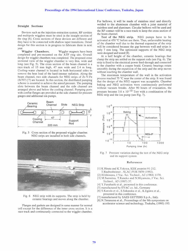
Fig. 6 NEG strip with its supports . The strip is held by ceramic bearings and moves along the chamber.
Flanges and gaskets are designed in same manner for normal cell except for the difference of the inner cross section. It is a race track and continuously connected to the wiggler chamber.
For bellows, it will be made of stainless steel and directly welded to the aluminum chamber with a joint material of stainless steel and aluminum. Circular bellows will be used and the RF contact will be a race-track to keep the cross section of the beam channel.
Test of the NEG strip. NEG pumps have to be activated at 450 °C before use them. Thus, unfavorable heating of the chamber waH due to the thermal expansion of the strip will be considered because the gap between wall and strips is only 7 mm long. The optimized supports of the NEG strip were designed and tested [8].
At a half height of the chamber, ceramic bearings that clamp the strip are settled on the support rods (see Fig. 6). The strip is fixed to the electrical power feed-through and connected to the chamber with a copper braid. Ceramic bearings rotate smoothly during the expansion of the strip and the strip moves without touching the chamber wall.
The maximum temperature of the waH in the activation process reached 75 °C near the center of the strip. It was found that the design of the NEG support was acceptable. Chamber baking and NEG activation were continuously performed without vacuum breaks. After 90 hours of evacuatIOn, the pressure became 3.6 x 10- \0 Torr with a combination of the NEG strip and the ion pump (see Fig. 7).
10. 5
1 0. 6
0 1 0. 7 t:.
......... ~ ..
~ I Activation
CD :; 1 0. 8 <Jl <Jl Q>
a: 1 0. 9
1 0. 10
1 10 1000 Pumping time (hr)
Fig. 7 Pressure variation during the test of the NEG strip and its support system.
References
r I] K.Hirata and K.Yokoya, KEK preprint 91-212. T.Raubenheimer , SLAC-PUB -5859 (1992) .
[2] H.lshimaru, J Vac . Sci . Technol., A2 (1984) 1170. [3] M.Suemitsu, T.Kaneko and N.Miyamoto, J Vac. Sci .
Techno!.. A5 (1987) 37 . [4 J Y.Funahashi et aI., presented in this conference. [5] manufactured by EVAC co. ltd ., Germany [6J S.Kuroda et aI., S.Sakanaka et aI. , K.Egawa et aI. ,
presented in this conference. [7] manufactured by SAES GETTERS S.p.A., Italy .. [8] N.Terunuma et aI., Proceedings of the 9th symposIUm on
accelerator science and technology, Tsukuba, (1993) 193.
Proceedings of the 1994 International Linac Conference, Tsukuba, Japan
79