Embed Size (px)
Citation preview
In
Proceedings IEEE Visualization 2002
, pages 395–402. IEEE Computer Society Press, 2002.
QuadTIN: Quadtree based Triangulated Irregular Networks
Renato Pajarola Marc Antonijuan Roberto Lario
Computer Graphics Lab Multimedia Technology Integration Center Dpto. Arquitectura de Computadores y AutomáticaInformation & Computer Science Department School of Engineering Fac. de CC. Físicas
University of California Irvine La Salle University Universidad Complutense [email protected] [email protected] [email protected]
ABSTRACT
Interactive visualization of large digital elevation models is of con-tinuing interest in scientific visualization, GIS, and virtual realityapplications. Taking advantage of the regular structure of grid dig-ital elevation models, efficient hierarchical multiresolution trian-gulation and adaptive level-of-detail (LOD) rendering algorithmshave been developed for interactive terrain visualization. Despitethe higher triangle count, these approaches generally outperformmesh simplification methods that produce irregular triangulatednetwork (TIN) based LOD representations. In this project we com-bine the advantage of a TIN based mesh simplification preprocesswith high-performance quadtree based LOD triangulation and ren-dering at run-time. This approach, called QuadTIN, generates anefficient quadtree triangulation hierarchy over any irregular pointset that may originate from irregular terrain sampling or fromreducing oversampling in high-resolution grid digital elevationmodels.
CR Categories:
I.3.5 Computational Geometry and Object Mod-eling; I.3.3 Image Generation; E.2 Data Storage Representation
Keywords:
multiresolution triangulation, real-time terrain visual-ization, triangulated irregular networks, level-of-detail
1. INTRODUCTION
Efficient interactive visualization of very large
digital elevationmodels
(DEMs) is important in a number of application domainssuch as scientific visualization, GIS, virtual reality, flight simula-tion, military command & control, or interactive 3D games. Griddigital terrain data sets can easily reach several million verticeswhile graphics hardware accelerators may be capable of interac-tively render only a fraction of this at 20 frames or more per sec-ond. Due to the generally very large size of DEM terrain data setsand the limited rendering power of graphics systems, efficient
level-of-detail
(LOD) based mesh simplification is required toreduce the geometric scene complexity adaptively and withoutleading to an intolerable poor visual representation.
Taking advantage of the regular grid structure of commonDEM terrain data sets, quadtree based hierarchical multiresolutiontriangulation methods [18] have proven to be very efficient interms of LOD selection, triangulation and rendering performance.On the other hand, TIN based triangle mesh simplification meth-ods [5, 2] are generally superior in the triangle count for a givenLOD error threshold and allow arbitrary irregular input point datasets. Achieving the high performance of regular quadtree basedmultiresolution triangulation on irregular point sets is hard toachieve.
Having uniform high-resolution terrain data available does notmean that this uniform resolution is desired everywhere at all.Therefore, quadtree based methods do not provide an adequateapproach. However, TIN based simplification in a preprocess toeliminate unnecessary detail data (see our examples in Section 5)can optimally remove this redundancy. The remaining data set isnot anymore a conforming grid that is directly usable in quadtreebased methods.
Our method imposes an efficient quadtree triangulation hierar-chy on any irregular TIN based input,
1
thus the name
QuadTIN
.The proposed approach is able to provide fast quadtree basedadaptive LOD triangulation and real-time rendering of irregularterrain height-field data using additional Steiner points. Further-more, due to the imposed restricted quadtree triangulation on theTIN input any arbitrary LOD can be represented as one single tri-angle strip. See Figure 1 for an example.
The remainder of the paper is organized as follows. Section 2presents a short overview on related work and in Section 3 wereview the quadtree based triangulation method underlying ourapproach. In Section 4 we describe our QuadTIN triangulationapproach. Experiments are presented in Section 5 and Section 6concludes the paper.
2. RELATED WORK
There has been extensive work on TIN based triangle mesh simpli-fication, refinement methods and multiresolution triangulation forterrains that goes beyond the scope of this paper. We refer theinterested reader to the literature for more details (see [3, 5, 6, 9,12, 13, 19]). Because such TIN based methods work on arbitraryirregular point input data sets they tend to have higher computa-
1. irregular triangulation of elevation points in the 2D projection
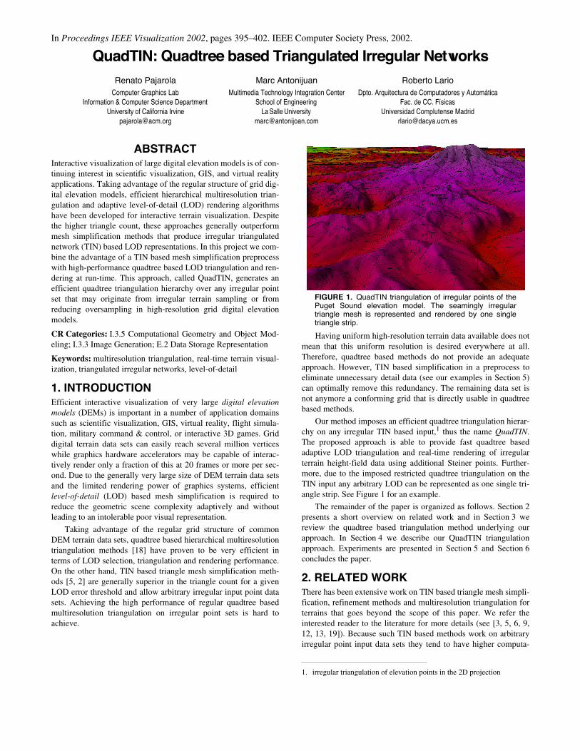
FIGURE 1.
QuadTIN triangulation of irregular points of thePuget Sound elevation model. The seamingly irregulartriangle mesh is represented and rendered by one singletriangle strip.
2
tional costs associated with simplification and refinement opera-tions compared to regular hierarchical methods. Furthermore, TINbased multiresolution hierarchies require more complex and costlydata structures as well to capture irregular refinement or simplifi-cation operations and adjacency relations. Their main advantagesare handling of arbitrary point distributions and superior (smaller)triangle counts for given LOD thresholds.
Adaptive quadtree based hierarchical multiresolution triangu-lations have been studied in the literature for adaptive triangulationof grid-digital terrain elevation models [1, 7, 8, 10, 14, 16, 23]. In[18] we discuss advantages and differences between the variousapproaches of this class of quadtree [16, 23] or bintree [1, 7, 8, 14]triangulations. These methods take advantage of the regular gridstructure to create an efficient multiresolution triangulation hierar-chy. The main advantages are simple construction of the multires-olution hierarchy, fast LOD selection and efficient rendering. Themain disadvantages are the suboptimal size of an adaptive LODmesh compared to TINs and the restricted applicability.
In [26] semi-regular, quasi-regular and irregular 4-k meshesare presented. However, this type of irregularity is quite differentfrom what we are considering in this paper. In [26], the semi- andquasi-regular 4-8 meshes are basically
subdivision
methods [25],and the irregular 4-8 meshes are adaptive tesselations of paramet-ric or implicit surfaces. In contrast, this paper discusses how to useany given irregular point set in 2D with additional Steiner points tocreate a restricted quadtree triangulation.
3. RESTRICTED QUADTREE TRIANGULATION
The
restricted quadtree triangulation
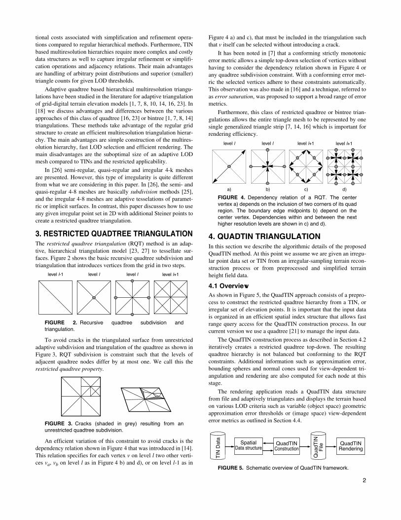
(RQT) method is an adap-tive, hierarchical triangulation model [23, 27] to tessellate sur-faces. Figure 2 shows the basic recursive quadtree subdivision andtriangulation that introduces vertices from the grid in two steps.
FIGURE 2.
Recursive quadtree subdivision andtriangulation.
To avoid cracks in the triangulated surface from unrestrictedadaptive subdivision and triangulation of the quadtree as shown inFigure 3, RQT subdivision is constraint such that the levels ofadjacent quadtree nodes differ by at most one. We call this the
restricted quadtree property
.
FIGURE 3.
Cracks (shaded in grey) resulting from anunrestricted quadtree subdivision.
An efficient variation of this constraint to avoid cracks is thedependency relation shown in Figure 4 that was introduced in [14].This relation specifies for each vertex
v
on level
l
two other verti-ces
v
a
,
v
b
on level
l
as in Figure 4 b) and d), or on level
l
-1 as in
Figure 4 a) and c), that must be included in the triangulation suchthat
v
itself can be selected without introducing a crack.
It has been noted in [7] that a conforming strictly monotonicerror metric allows a simple top-down selection of vertices withouthaving to consider the dependency relation shown in Figure 4 orany quadtree subdivision constraint. With a conforming error met-ric the selected vertices adhere to these constraints automatically.This observation was also made in [16] and a technique, referred toas
error saturation
, was proposed to support a broad range of errormetrics.
Furthermore, this class of restricted quadtree or bintree trian-gulations allows the entire triangle mesh to be represented by onesingle generalized triangle strip [7, 14, 16] which is important forrendering efficiency.
FIGURE 4.
Dependency relation of a RQT. The centervertex a) depends on the inclusion of two corners of its quadregion. The boundary edge midpoints b) depend on thecenter vertex. Dependencies within and between the nexthigher resolution levels are shown in c) and d).
4. QUADTIN TRIANGULATION
In this section we describe the algorithmic details of the proposedQuadTIN method. At this point we assume we are given an irregu-lar point data set or TIN from an irregular-sampling terrain recon-struction process or from preprocessed and simplified terrainheight field data.
4.1 Overview
As shown in Figure 5, the QuadTIN approach consists of a prepro-cess to construct the restricted quadtree hierarchy from a TIN, orirregular set of elevation points. It is important that the input datais organized in an efficient spatial index structure that allows fastrange query access for the QuadTIN construction process. In ourcurrent version we use a quadtree [21] to manage the input data.
The QuadTIN construction process as described in Section 4.2iteratively creates a restricted quadtree top-down. The resultingquadtree hierarchy is not balanced but conforming to the RQTconstraints. Additional information such as approximation error,bounding spheres and normal cones used for view-dependent tri-angulation and rendering are also computed for each node at thisstage.
The rendering application reads a QuadTIN data structurefrom file and adaptively triangulates and displays the terrain basedon various LOD criteria such as variable (object space) geometricapproximation error thresholds or (image space) view-dependenterror metrics as outlined in Section 4.4.
FIGURE 5.
Schematic overview of QuadTIN framework.
level llevel l-1 level l level l+1
level l+1level l level l level l+1
a) b) c) d)
Spatial QuadTIN QuadTIN
TIN
Dat
a
Qua
dTIN
FileData structure Construction Rendering
3
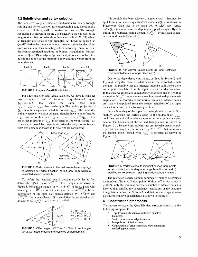
4.2 Subdivision and vertex selection
The recursive irregular quadtree subdivision by binary trianglesplitting and vertex selection for corresponding edge bisection is acrucial part of the QuadTIN construction process. The trianglesubdivision as shown in Figure 2 is basically a special case of thelongest side bisection triangle refinement method [20, 24] whereall triangles are isosceles right-triangles. As shown in Figure 6, inQuadTIN triangles are not anymore isosceles right-triangles. How-ever, we maintain the alternating split-base for edge bisection as inthe regular restricted quadtree or bintree triangulation. Further-more, in QuadTIN an edge is (geometrically) bisected not by intro-ducing the edge’s actual midpoint but by adding a vertex from theinput data set.
FIGURE 6.
Irregular QuadTIN subdivision.
For edge bisection and vertex selection, we have to considertwo triangles and forming a quadrilateral region
that share the same base edge that is to be split. The vertical projection of
into the
x,y
-plane is called the domain . The basic ideais that whenever two base-adjacent triangles have to be refined byedge bisection of their base edge , the vertex clos-est to the midpoint of is selected as shown in Figure 7 a).However, to avoid bad aspect-ratio triangles only points from arestricted domain as shown in Figure 7 b) are considered.
FIGURE 7.
Vertex closest to the midpoint of base edge
e
t,t’
is selected for edge bisection a) but only from within arestricted search domain b).
To define the restricted search domain exactly let us firstdefine the
offset region
of a triangle
t
as shown inFigure 8. For a given triangle in the
x,y
-plane withbase edge and offset factor
f
we define to be theintersection of the open half spaces defined by and
. For a quadrilateral we define the restricted searchdomain to be .
FIGURE 8.
Offset region
∂
t
offset
for
f
= 50% of one triangle
∂
t
=(
A,B,C
)
used to define the restricted search domain.
It is possible that base-adjacent triangles and that must besplit form a
non convex
quadrilateral domain as shown inFigure 9 a). Care has to be taken not to select any vertex
that may cause overlapping or flipped triangles. By def-inition, the restricted search domain avoids such degen-eracies as shown in Figure 9 b).
FIGURE 9.
Non-convex quadrilateral a), and restrictedpoint search domain for edge bisection b).
Due to the dependency constraints, outlined in Section 3 andFigure 4, irregular point distributions and the restricted searchdomain it is possible that two triangles must be split where thereare no points available from the input data set for edge bisection.In that case we insert a so called
Steiner point
(see also [4]) withinthe region to guarantee a matching restricted quadtree tri-angulation. The coordinates and normal vectors of Steiner pointsare locally interpolated from the nearest neighbors of the inputdata set as outlined in the following section.
On the boundary of the input data, triangle subdivision differsslightly. Choosing the vertex closest to the midpoint of could lead to a situation where unprocessed input points are out-side of the boundary of the refined triangulation as shown inFigure 10 a). To avoid this problem and preserve the
inside-bound-ary
relation at any time, the vertex that minimizesthe largest angle formed with is selected as shown inFigure 10 b).
FIGURE 10.
Vertex closest to midpoint causes input pointsto be outside the boundary after edge bisection a), and b)modified vertex selection retaining inside-boundary relation.
The restricted search domain parameter
f
mainly determinesthe number of inserted Steiner points. Without offset restrictions,
f
= 100%, only the minimal necessary number of Steiner points isinserted that satisfies the dependency restrictions of the quadtreetriangulation outlined in Section 3, and that prevents flipped trian-gles due to concave quadrilaterals as shown in Figure 9.
4.3 Construction preprocess
The process to create the QuadTIN data structure consists of thefollowing components:
•
Top-down construction of restricted quadtreehierarchy.
•
Vertex selection for edge bisection.
•
Interpolation of Steiner points.
•
Computation of error metric and view-dependentrendering parameters.
level llevel l-1 level l level l+1
vcenter
t t'Qt t', t t'∪=et t', tbase t'base= =Qt t', ∂Qt t',
et t', v ∂Qt t',∈et t',
a) b)
restrictedsearch domain
base edge et,t’
t t’
∂toffset
∂t A B C, ,( )=e BC= ∂t
offset
BoffAoff
AoffCoff Qt t',∂Qt t',
offset ∂toffset ∂t'offset∩=
∂t
A
C
V
Aoff
Boff
Coff V = (B + C) / 2Aoff = V + f · (A - V)Boff = V + f · (B - V)Coff = V + f · (C - V)
∂toffset
B
t t'∂Qt t',
v ∂Qt t',∈∂Qt t',
offset
a) b)
∂Qt,t’
t’
t
∂Qt t',offset
tbase
vsplit ∂toffset
∈tbase
a) b)
boundary
tbase tbase
vsplit

4
Top-down hierarchy construction: The QuadTIN hierarchy H isinitialized with a quadtree root node containing two trianglesdefined by the corners and one diagonal of the bounding box of theinput data set. In general, the corners of the bounding box areinterpolated Steiner points. The hierarchy is iteratively created bysubdividing the leaf nodes and triangles of the quadtree H inbreadth-first order and center-vertices first (see Figure 6) whichallows preserving the restricted quadtree property at any time dur-ing the construction process. If a triangle t has to be subdivided,first it is checked that the base-adjacent triangle t’ already exists. Ifnot, subdivision is propagated to the parent triangle of t’ first.Unless a subdivision is induced by a dependency relation, the top-down triangle subdivision stops if no more input points are within
.
Edge bisection: As outlined in the previous section, for each sub-division of triangles and the input point set must be searchedfor candidate vertices within the restricted search domain to perform edge bisection. To support such spatial search queriesefficiently, the input points are loaded into a spatial indexing struc-ture. We currently use a region quadtree [21] to quickly select asubset of input points within the bounding box of . Then wereduce this subset to valid candidate points within .Finally, the vertex closest to the midpoint of isselected for edge bisection and removed from the input point set ormarked as used. If no suitable input point can be found,
, a new Steiner point is inserted.
Steiner points: To interpolate the coordinates and normal vectorsof Steiner points, again the input point set is searched. For everySteiner vertex vS that is inserted in at least three and up tofour closest points within from the input data set, or cornersof the incident triangles and , are selected. The z-coordinateand normal vector of vS are averaged from these closest points.The x,y-coordinates are set to the midpoint of the bisected edge
. If not initially given, the vertex normals of the input pointsare calculated from the TIN input file as average from the adjacenttriangles.
Error metric: The error metric that QuadTIN uses is the L∞ normof the vertical distance (terrain elevation dimension) of vertices tothe triangulated surface. Let us denote the minimum vertical dis-tance of a vertex v to two triangles and by , and let
be the vertex selected for subdividing the base edge .Therefore, the error of is initialized to
. (EQ 1)
This error metric provides a conservative LOD triangulation,the top-down vertex selection and triangle subdivision can bestopped at nodes with below a given tolerance. By defi-nition of the error metric, stopping selection at with
below the given error threshold guarantees that there isno other vertex within farther than from the cur-rent triangles t and t’. Because this error metric is not guaranteed tobe monotonic, cracks in the triangulation have to be avoided bypropagating subdivision according to the dependency relationsshown in Figure 4. Thus propagated subdivisions must verify theerror threshold as well. Note that in [15] a view-dependent errormetric was proposed that is monotonic and does not require depen-dency resolution via split propagation.
Rendering parameters: Besides the geometric approximationerror that is stored with each vertex, each node of the
QuadTIN hierarchy also stores bounding sphere (center h.c andradius h.r) and bounding normal cone [22] (cone axis h.n and semiopening angle h.θ) parameters used for view-dependent triangula-tion and rendering. The bounding sphere of a node h encloses allvertices, and the bounding normal cone bounds all triangle nor-mals of descendants of h. These parameters are computed bottom-up after the basic quadtree data structure has been constructed.
4.4 Real-time renderingOur interactive visualization application reads the preprocessedQuadTIN data structure from a binary file. The real-time renderingprocess performs the following steps for each frame:
1. View-dependent vertex selection.2. Dependency resolution.3. Triangle strip construction.4. Rendering.
The top-down traversal of the QuadTIN hierarchy H for vertexselection is similar to the algorithms presented in [16, 23]. How-ever, for a fly-through application vertices are selected based on aview-dependent (image space) error metric as outlined below. Dueto this view-dependent vertex selection the RQT constraints haveto be satisfied by including all vertices according to the depen-dency relation shown in Figure 4. Dependency resolution is effi-ciently performed in linear time with respect to the size of thegenerated triangle mesh as shown in [16] and is not further dis-cussed here.
Furthermore, due to the imposed restricted quadtree hierarchyon the TIN input data set, including a few additional Steinerpoints, the presented QuadTIN approach can represent differentLOD triangulations of an irregular point set using only one singletriangle strip (with swap operations). Note that also the trianglestrip generation algorithm [16] is linear in time with respect to thenumber of rendered triangles.
View-dependent vertex selection: The vertex selection takesthree view-dependent selection criteria into account: view-frustumculling, back-face culling and screen projection tolerance. Thesecriteria allow efficient back-tracking during the recursive traversalof the QuadTIN hierarchy H for vertex selection. If the boundingsphere of a node does not intersect the view frustum(approximated by a viewing cone) or if the bounding normal coneindicates a completely back-facing region, recursive vertex selec-tion can be stopped at this node h. For performance reasons Quad-TIN computes view-frustum and back-face culling similar to [17]using only a few floating point operations, see also Figure 11. Weassume that the viewpoint e and semi-angle ω (as well as its sine,cosine and tangens) of the viewing cone are given for each frame.Furthermore, for each node we know its bounding sphere(c, r) and bounding normal cone (n,θ).
View-frustum culling as shown in Figure 11 a) is performed if or . Using the rules
and thiscan be rewritten to
. (EQ 2)
Equation 2 can efficiently be evaluated without trigonometricfunctions by using a dot-product and an additional division. can be precomputed once aslong as the FOV aperture angle does not change between framesand . A few additional relations such as
⇒ continue selection, ⇒ continue selec-
∂Qt t',
t t'∂Qt t',
offset
Qt t',∂Qt t',
offset
v ∂Qt t',offset
∈ et t',
v v ∂Qt t',offset
∈{ } ∅=
Qt t',Qt t',
t t'
et t',
t t' d v Qt t',,( )vsplit et t',
vsplit
E vsplit( ) maxv ∂Qt t',∈ d v Qt t',,( )( )=
E vsplit( )vsplit
E vsplit( )∂Qt t', E vsplit( )
h H∈
h H∈
h H∈
γ α– ω> γ α–( )cos ω( )cos<α( )cos 90 α–( )sin= α β+( )sin α( )sin β( )sin+≤
γ( )cos α( )sin+ ω( )cos<
γ( )cos c e–( ) w•( ) c e–⁄=ω( )cos
α( )sin r c e–⁄=γ( )cos ω( )cos> c e– r<
5
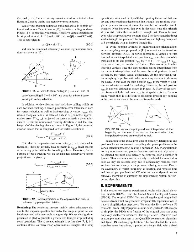
tion, and ⇒ stop selection need to be tested beforeEquation 2 can be used to stop recursive vertex selection.
While view-frustum culling as explained above is slightly dif-ferent and more efficient than in [17], back-face culling as shownFigure 11 b) is practically identical. Recursive vertex selection canbe stopped at node h if or .This is equivalent to
, (EQ 3)
and can be computed efficiently without trigonometric func-tions as shown in [17].
FIGURE 11. a) View-frustum culling if and b)
back-face culling if are used for efficient back-
tracking in vertex selection.
In addition to view-frustum and back-face culling which areused for back-tracking, a screen projection error tolerance is usedfor vertex selection as well as back-tracking. A vertex thatrefines triangles t and t’ is selected only if its geometric approxi-mation error projected on screen exceeds a given toler-ance τ. Given the normalized viewing direction w and the focallength d of the viewing plane as shown in Figure 12, the projectederror on screen that is compared to τ for vertex selection is
. (EQ 4)
Note that the approximation error as computed inEquation 1 does not actually have to occur at itself but canoccur at any point within the bounding sphere. Therefore, for thepurpose of back-tracking we use an adjusted conservative screenprojection error given by
. (EQ 5)
FIGURE 12. Screen projection of the approximation error isperformed by perspective division.
Rendering: The rendering process mainly takes advantage thatdue to the imposed quadtree hierarchy the irregular point set canbe triangulated with one single triangle strip. We use the algorithmpresented in [16] to generate a generalized triangle strip includingswap operations. The so created triangle strip (see also [7, 8, 14])contains almost as many swap operations as triangles. If a swap
operation is simulated in OpenGL by repeating the second last ver-tex and thus creating a degenerate line-triangle, the resulting trian-gle strip contains almost twice the number of actually visibletriangles. Note however, that even in the worst case this trianglestrip is still better then an indexed triangle list. This is becauseeven with swap operations no more than 2 vertices (amortized) pervisible triangle are processed for transform and lighting comparedto 3 per triangle with an indexed triangle list.
To avoid popping artifacts in multiresolution triangulationsvertex morphing was proposed in [11] to smoothen the transitionbetween different LODs. In vertex morphing, a vertex v is firstinserted at an interpolated start position vstart and then smoothlytranslated to its end position vend by over some time, or number of frames. This works well wheninserting vertices since the start position can be interpolated fromthe current triangulation and because the end position is welldefined by the vertex’ actual coordinates. On the other hand, ver-tex morphing is problematic when removing vertices to decreasethe LOD. In that case the start position vstart is the vertex v’s cur-rent coordinates as used for rendering. However, the end positionvend is not well defined as shown in Figure 13. If any of the verti-ces, from which the end point vend is interpolated, is itself a mor-phing vertex then it is difficult to efficiently prevent any poppingat the time when v has to be removed from the mesh.
FIGURE 13. Vertex morphing endpoint interpolation at thebeginning of the morph a) and at the end when theinterpolated vertices are modified as well.
In addition to the above problems of correctly determining endpositions for vertex removal, morphing also poses problems in thevertex selection process. Creating a particular LOD triangulation isnot anymore a one-step process because vertices not only have tobe selected but must also actively be removed over a number offrames. Thus vertices must be actively scheduled for removal assoon as they are selected only due to dependency relations fromvertices that are already in the process of being removed. Due tothe asymmetry of vertex morphing at insertion and removal timeand due to open problems in LOD selection under dynamic vertexremoval, morphing is currently not implemented within our ren-dering algorithm.
5. EXPERIMENTSIn this section we present experimental results with digital eleva-tion models (DEMs) from the United States Geological Survey(USGS). The original DEM files are all regular grid height-fielddata sets from which we generated irregular TIN representations ina mesh simplification preprocess. We used the Terra software [9]available from http://graphics.cs.uiuc.edu/~garland/CMU/scape/to simplify the DEMs to a fraction of the original data size usingonly very small error tolerances. The so generated TINs were usedas example input data sets to our QuadTIN construction algorithmand QuadTIN rendering application. The downloaded Terra soft-ware has some limitations, it processes a height-field with a fixed
c e–( ) w• r–<
β θ+ 90°< β( )cos 90° θ–( )cos>
β( )cos θ( )sin>
θ
e
n
c
β
c-e ω
we
c γ
α
r
wc-e
a) b)
γ α– ω>
β θ+ 90°<
vsplit
E vsplit( )
Escreen
E vsplit( ) d⋅
vsplit e–( ) w⋅----------------------------------=
E vsplit( )vsplit
Escreen
E vsplit( ) d⋅
vsplit e–( ) w⋅ r–------------------------------------------=
vsplit-e
we
vsplit r
d
E(vsplit)
viewing plane
v 1 t–( ) vstart t vend⋅+⋅=
vstart=vvend=0.5(v1+v2)
v1
v2
vstart vend
v1’
v2’
a) b)
6
spacing of one unit between points in x,y. To avoid any loss of res-olution in the elevation dimension we did not scale (down) the ele-vation accordingly but processed the input file conservativelyusing Terra with exaggerated elevation.
We used the following terrain data sets to test our QuadTINapproach: Isabel Valley, Mindego Hill, Palo Alto,1 San Jose1 (allavailable from http://bard.wr.usgs.gov/), Puget Sound, and GrandCanyon (both from http://www.cc.gatech.edu/projects/large_models/).
5.1 QuadTIN constructionTable 1 shows results of the preprocess using Terra mesh simplifi-cation and the QuadTIN construction process. The Terra prepro-cess was conducted on a Sun Enterprise 450 server with 4GBmemory and running on one of the four 296MHz UltraSPARC-IICPUs. The QuadTIN construction process was performed on a SunUltra60 workstation with a 450MHz UltraSPARC-II and 512MBmain memory.
Despite the fact that the QuadTIN construction process per-forms demanding spatial search operations on the TIN input data,executes complicated distance and error metric calculations,inserts new Steiner points and computes a bounding sphere andbounding normal cone hierarchy it is very efficient. The construc-tion process operated at a rate of processing more than 4300 pointsper second for most input files. One can also observe that the ratioof inserted Steiner points in comparison to the input data set isonly about 23% for an offset factor of f = 80% for the restrictedsearch domain (see also Section 4.2).
In Table 1 we also show the unusual results obtained with theGrand Canyon data set. This data set is unlike the others in severalaspects. It has a very poor resolution of only 8 bits in the elevationdimension (only 256 different altitude values). This causes theTerra preprocess to perform poorly in terms of mesh simplifica-tion. The unusual simplification and extreme point distributionalso causes the QuadTIN construction to perform poorly. Alto-gether, this outlier data set performs about 2 times worse in allaspects than the other data sets.
5.2 Triangulation and renderingIn Figure 14 we show the numbers of selected vertices for differentobject-space geometric approximation error thresholds for a
subset of the Palo Alto data set. We com-pared a plain restricted quadtree triangulation (RQT) built on thefull resolution height-field, and our QuadTIN approach with twodifferent Terra preprocess variants to corresponding simplifica-tions with Terra which are single resolution meshes. Despite the
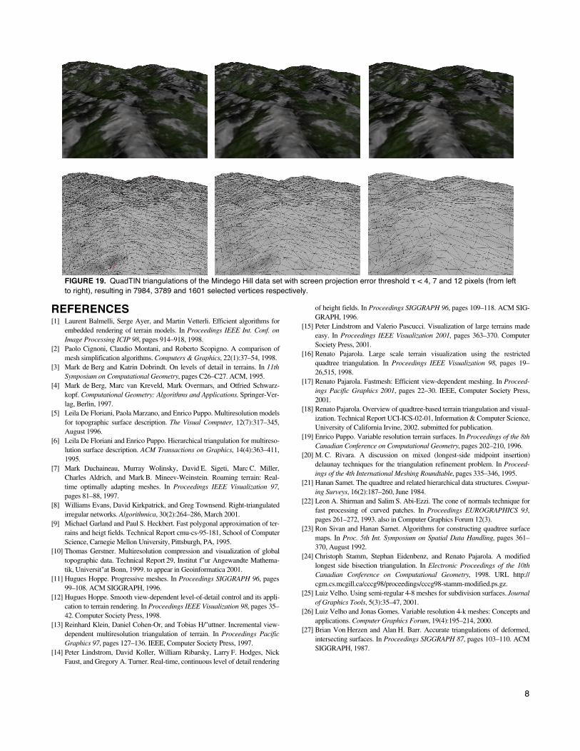
added Steiner points our QuadTIN approach outperforms the regu-lar grid RQT method significantly in terms of selected vertices forthe same LOD. The Terra results are shown for comparison onlysince Terra provides only discrete simplifications and is not a mul-tiresolution method. Figure 19 illustrates adaptive QuadTIN trian-gulation for a perspective view of the Mindego Hill data set atvarying image-space error thresholds τ.
FIGURE 14. Number of vertices used to represent a LODtriangulation for different object-space approximation errors.
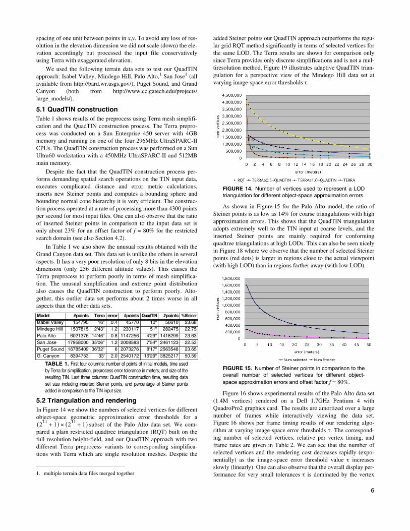
As shown in Figure 15 for the Palo Alto model, the ratio ofSteiner points is as low as 14% for coarse triangulations with highapproximation errors. This shows that the QuadTIN triangulationadopts extremely well to the TIN input at coarse levels, and theinserted Steiner points are mainly required for conformingquadtree triangulations at high LODs. This can also be seen nicelyin Figure 18 where we observe that the number of selected Steinerpoints (red dots) is larger in regions close to the actual viewpoint(with high LOD) than in regions farther away (with low LOD).
FIGURE 15. Number of Steiner points in comparison to theoverall number of selected vertices for different object-space approximation errors and offset factor f = 80%.
Figure 16 shows experimental results of the Palo Alto data set(1.4M vertices) rendered on a Dell 1.7GHz Pentium 4 withQuadroPro2 graphics card. The results are amortized over a largenumber of frames while interactively viewing the data set.Figure 16 shows per frame timing results of our rendering algo-rithm at varying image-space error thresholds τ. The correspond-ing number of selected vertices, relative per vertex timing, andframe rates are given in Table 2. We can see that the number ofselected vertices and the rendering cost decreases rapidly (expo-nentially) as the image-space error threshold value τ increasesslowly (linearly). One can also observe that the overall display per-formance for very small tolerances τ is dominated by the vertex1. multiple terrain data files merged together
Model #points Terra error #points QuadTIN #points %SteinerIsabel Valley 154795 16" 0.4 45770 10" 56610 23.68Mindego Hill 1507815 2'43" 1.2 230117 51" 282475 22.75Palo Alto 6021376 14'46" 0.8 1147256 4'29" 1418299 23.63San Jose 17958000 35'06" 1.2 2008583 7'54" 2461123 22.53Puget Sound 16785409 36'32" 6 2073276 8'17" 2563548 23.65G. Canyon 8394753 33' 2.0 2540172 16'29" 3825217 50.59
TABLE 1. First four columns: number of points of initial models, time usedby Terra for simplification, preprocess error tolerance in meters, and size of theresulting TIN. Last three columns: QuadTIN construction time, resulting dataset size including inserted Steiner points, and percentage of Steiner pointsadded in comparison to the TIN input size.
211
1+( ) 211
1+( )×
7
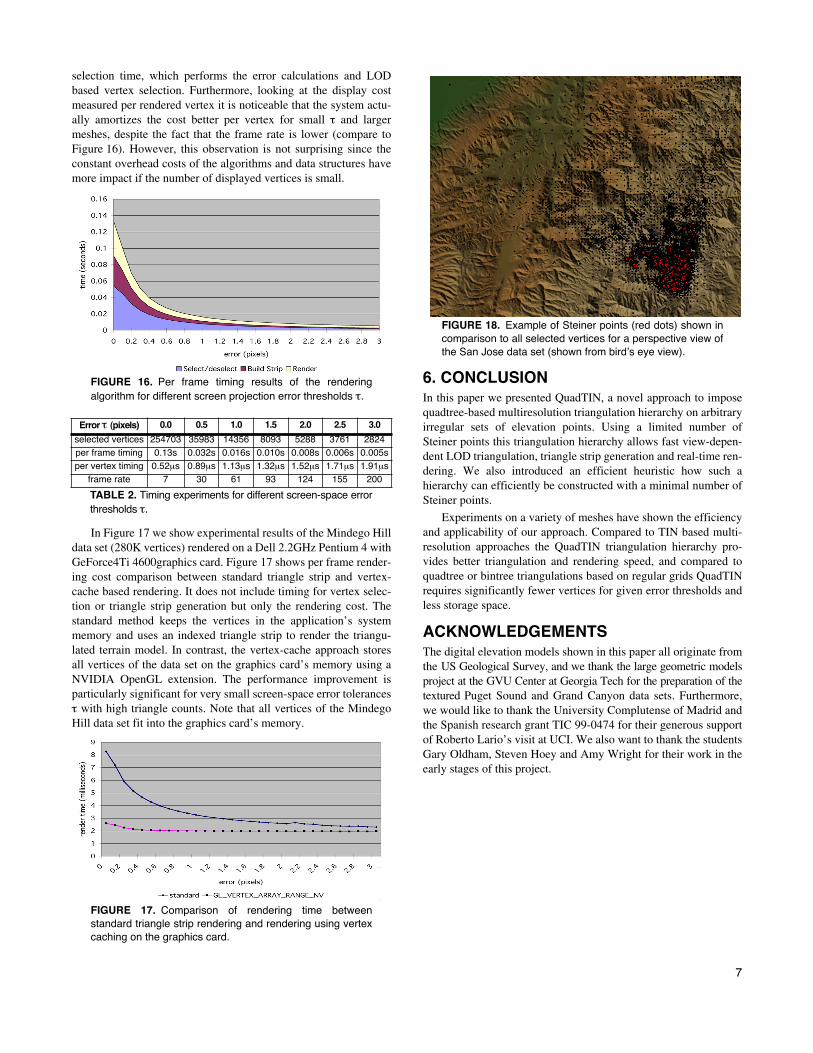
selection time, which performs the error calculations and LODbased vertex selection. Furthermore, looking at the display costmeasured per rendered vertex it is noticeable that the system actu-ally amortizes the cost better per vertex for small τ and largermeshes, despite the fact that the frame rate is lower (compare toFigure 16). However, this observation is not surprising since theconstant overhead costs of the algorithms and data structures havemore impact if the number of displayed vertices is small.
FIGURE 16. Per frame timing results of the renderingalgorithm for different screen projection error thresholds τ.
In Figure 17 we show experimental results of the Mindego Hilldata set (280K vertices) rendered on a Dell 2.2GHz Pentium 4 withGeForce4Ti 4600graphics card. Figure 17 shows per frame render-ing cost comparison between standard triangle strip and vertex-cache based rendering. It does not include timing for vertex selec-tion or triangle strip generation but only the rendering cost. Thestandard method keeps the vertices in the application’s systemmemory and uses an indexed triangle strip to render the triangu-lated terrain model. In contrast, the vertex-cache approach storesall vertices of the data set on the graphics card’s memory using aNVIDIA OpenGL extension. The performance improvement isparticularly significant for very small screen-space error tolerancesτ with high triangle counts. Note that all vertices of the MindegoHill data set fit into the graphics card’s memory.
FIGURE 17. Comparison of rendering time betweenstandard triangle strip rendering and rendering using vertexcaching on the graphics card.
FIGURE 18. Example of Steiner points (red dots) shown incomparison to all selected vertices for a perspective view ofthe San Jose data set (shown from bird’s eye view).
6. CONCLUSIONIn this paper we presented QuadTIN, a novel approach to imposequadtree-based multiresolution triangulation hierarchy on arbitraryirregular sets of elevation points. Using a limited number ofSteiner points this triangulation hierarchy allows fast view-depen-dent LOD triangulation, triangle strip generation and real-time ren-dering. We also introduced an efficient heuristic how such ahierarchy can efficiently be constructed with a minimal number ofSteiner points.
Experiments on a variety of meshes have shown the efficiencyand applicability of our approach. Compared to TIN based multi-resolution approaches the QuadTIN triangulation hierarchy pro-vides better triangulation and rendering speed, and compared toquadtree or bintree triangulations based on regular grids QuadTINrequires significantly fewer vertices for given error thresholds andless storage space.
ACKNOWLEDGEMENTSThe digital elevation models shown in this paper all originate fromthe US Geological Survey, and we thank the large geometric modelsproject at the GVU Center at Georgia Tech for the preparation of thetextured Puget Sound and Grand Canyon data sets. Furthermore,we would like to thank the University Complutense of Madrid andthe Spanish research grant TIC 99-0474 for their generous supportof Roberto Lario’s visit at UCI. We also want to thank the studentsGary Oldham, Steven Hoey and Amy Wright for their work in theearly stages of this project.
Error τ (pixels) 0.0 0.5 1.0 1.5 2.0 2.5 3.0
selected vertices 254703 35983 14356 8093 5288 3761 2824per frame timing 0.13s 0.032s 0.016s 0.010s 0.008s 0.006s 0.005sper vertex timing 0.52µs 0.89µs 1.13µs 1.32µs 1.52µs 1.71µs 1.91µs
frame rate 7 30 61 93 124 155 200
TABLE 2. Timing experiments for different screen-space errorthresholds τ.
8
FIGURE 19. QuadTIN triangulations of the Mindego Hill data set with screen projection error threshold τ < 4, 7 and 12 pixels (from leftto right), resulting in 7984, 3789 and 1601 selected vertices respectively.
REFERENCES[1] Laurent Balmelli, Serge Ayer, and Martin Vetterli. Efficient algorithms for
embedded rendering of terrain models. In Proceedings IEEE Int. Conf. onImage Processing ICIP 98, pages 914–918, 1998.
[2] Paolo Cignoni, Claudio Montani, and Roberto Scopigno. A comparison ofmesh simplification algorithms. Computers & Graphics, 22(1):37–54, 1998.
[3] Mark de Berg and Katrin Dobrindt. On levels of detail in terrains. In 11thSymposium on Computational Geometry, pages C26–C27. ACM, 1995.
[4] Mark de Berg, Marc van Kreveld, Mark Overmars, and Otfried Schwarz-kopf. Computational Geometry: Algorithms and Applications. Springer-Ver-lag, Berlin, 1997.
[5] Leila De Floriani, Paola Marzano, and Enrico Puppo. Multiresolution modelsfor topographic surface description. The Visual Computer, 12(7):317–345,August 1996.
[6] Leila De Floriani and Enrico Puppo. Hierarchical triangulation for multireso-lution surface description. ACM Transactions on Graphics, 14(4):363–411,1995.
[7] Mark Duchaineau, Murray Wolinsky, David E. Sigeti, Marc C. Miller,Charles Aldrich, and Mark B. Mineev-Weinstein. Roaming terrain: Real-time optimally adapting meshes. In Proceedings IEEE Visualization 97,pages 81–88, 1997.
[8] Williams Evans, David Kirkpatrick, and Greg Townsend. Right-triangulatedirregular networks. Algorithmica, 30(2):264–286, March 2001.
[9] Michael Garland and Paul S. Heckbert. Fast polygonal approximation of ter-rains and heigt fields. Technical Report cmu-cs-95-181, School of ComputerScience, Carnegie Mellon University, Pittsburgh, PA, 1995.
[10] Thomas Gerstner. Multiresolution compression and visualization of globaltopographic data. Technical Report 29, Institut f"ur Angewandte Mathema-tik, Universit"at Bonn, 1999. to appear in Geoinformatica 2001.
[11] Hugues Hoppe. Progressive meshes. In Proceedings SIGGRAPH 96, pages99–108. ACM SIGGRAPH, 1996.
[12] Hugues Hoppe. Smooth view-dependent level-of-detail control and its appli-cation to terrain rendering. In Proceedings IEEE Visualization 98, pages 35–42. Computer Society Press, 1998.
[13] Reinhard Klein, Daniel Cohen-Or, and Tobias H/"uttner. Incremental view-dependent multiresolution triangulation of terrain. In Proceedings PacificGraphics 97, pages 127–136. IEEE, Computer Society Press, 1997.
[14] Peter Lindstrom, David Koller, William Ribarsky, Larry F. Hodges, NickFaust, and Gregory A. Turner. Real-time, continuous level of detail rendering
of height fields. In Proceedings SIGGRAPH 96, pages 109–118. ACM SIG-GRAPH, 1996.
[15] Peter Lindstrom and Valerio Pascucci. Visualization of large terrains madeeasy. In Proceedings IEEE Visualization 2001, pages 363–370. ComputerSociety Press, 2001.
[16] Renato Pajarola. Large scale terrain visualization using the restrictedquadtree triangulation. In Proceedings IEEE Visualization 98, pages 19–26,515, 1998.
[17] Renato Pajarola. Fastmesh: Efficient view-dependent meshing. In Proceed-ings Pacific Graphics 2001, pages 22–30. IEEE, Computer Society Press,2001.
[18] Renato Pajarola. Overview of quadtree-based terrain triangulation and visual-ization. Technical Report UCI-ICS-02-01, Information & Computer Science,University of California Irvine, 2002. submitted for publication.
[19] Enrico Puppo. Variable resolution terrain surfaces. In Proceedings of the 8thCanadian Conference on Computational Geometry, pages 202–210, 1996.
[20] M. C. Rivara. A discussion on mixed (longest-side midpoint insertion)delaunay techniques for the triangulation refinement problem. In Proceed-ings of the 4th International Meshing Roundtable, pages 335–346, 1995.
[21] Hanan Samet. The quadtree and related hierarchical data structures. Comput-ing Surveys, 16(2):187–260, June 1984.
[22] Leon A. Shirman and Salim S. Abi-Ezzi. The cone of normals technique forfast processing of curved patches. In Proceedings EUROGRAPHICS 93,pages 261–272, 1993. also in Computer Graphics Forum 12(3).
[23] Ron Sivan and Hanan Samet. Algorithms for constructing quadtree surfacemaps. In Proc. 5th Int. Symposium on Spatial Data Handling, pages 361–370, August 1992.
[24] Christoph Stamm, Stephan Eidenbenz, and Renato Pajarola. A modifiedlongest side bisection triangulation. In Electronic Proceedings of the 10thCanadian Conference on Computational Geometry, 1998. URL http://cgm.cs.mcgill.ca/cccg98/proceedings/cccg98-stamm-modified.ps.gz.
[25] Luiz Velho. Using semi-regular 4-8 meshes for subdivision surfaces. Journalof Graphics Tools, 5(3):35–47, 2001.
[26] Luiz Velho and Jonas Gomes. Variable resolution 4-k meshes: Concepts andapplications. Computer Graphics Forum, 19(4):195–214, 2000.
[27] Brian Von Herzen and Alan H. Barr. Accurate triangulations of deformed,intersecting surfaces. In Proceedings SIGGRAPH 87, pages 103–110. ACMSIGGRAPH, 1987.