Embed Size (px)
Citation preview
PortableHydrostatic Electric
Test Pump
Dixon800 High Street • Chestertown, MD 21620
800-355-1991 • Fax: 800-283-4966dixonvalve.com
ProcedureManual
2Electric Test Pump Dixon 800.355.1991
Dixon's Portable Electric Hydrostatic Test Pump (E.T.P.)
Features:
• Campbell Hausfeld 110 volt Portable Hydrostatic Electric Pump - Model (ETP)
• 2000 psi maximum test pressure
• 1.3 gpm fill rate (at 60 psi inlet water pressure)
• Quick connect garden hose coupler for water supply line
• 1/2" x 15 ft. Intermediate hose with brass Straight-Thru Quick Coupler x NPSM swivel connection.
• 1/2" brass Straight-Thru plug on pressure outlet
• 0 – 5000 psi bottom mount liquid filled pressure gauge
• Test caps, test plugs and pressure relief valves available. Consult the current Dixon Price List (DPL) for part numbers and pricing.
Recommendations
• If an extension cord is needed, the following wire sizes must be used: 25' Cord - not less than 14GA wire 50' Cord - not less than 12GA wire 100' Cord - not less than 10GA wire
Electric damage or personal injury can result from using improperly grounded outlets. Only a properly grounded 115 Volt outlet accepting three pronged plug should be used.
Serious damage can result from improper or inadequate electric set up. Fuses, wiring and electrical codes for proper amperage and grounding should be checked.
Make sure that no water / liquid is anywhere that could cause electric shock to the operator (i.e. on the floor or pump where it could come in contact with electric connection).
3Electric Test Pump Dixon 800.355.1991
Safety Precautions
• Electric 1. Pump is designed for the testing of rubber hose. We do not recommend it for any other application.
2. Adequate steps should be taken to protect property and personnel in the event of a failure during a test. These steps should include, but are not limited to the
following:
a) Only trained personnel should conduct hydrostatic testing. b) Use of safety glasses or shields for personnel conducting test and witnessing test. c) All personnel should be perpendicular to the test sample and at least 15 feet away. d) Place test sample in a protective enclosure. e) Restrain both ends of the test sample to prevent hose from whipping in case of a failure. f) If testing is done outside of a protective enclosure, restrict the movement of the couplings by the use of sandbags or other means. g) Use only water as a test fluid.
3. All incidental fittings, intermediate hose and piping should be rated at 3000 psi minimum.
4. Before removing or adjusting any part of the pumping system or test sample the following precautions should be exercised:
a) Shut off pump. b) Shut off water supply. c) Release pressure inside the test specimen (hose) through bleed valve.
4Electric Test Pump Dixon 800.355.1991
Procedure for Hydrostatic Testing using Electric Test Pump (E.T.P.)
It is very important to know the parameters of the test being conducted. Follow the hose manufacturer, recommendations of Rubber Manufacturers Association (R.M.A.), OSHA, or other regulatory bodies guidelines for specific test parameters. The test should be carefully monitored and all results recorded. Dixon recommends the followingsequence for a successful test:
1. Determine the test pressure of the assembly to be tested.
2. Make sure that the test caps or test plugs and all connections are tight on the test sample.
3. Connect test specimen (hose) to high pressure outlet intermediate hose. Connection between test specimen (hose) and intermediate hose should be tight.
4. Connect the bleed-off valve to the other end of the test sample.
5. Open the bleed-off valve on the test sample.
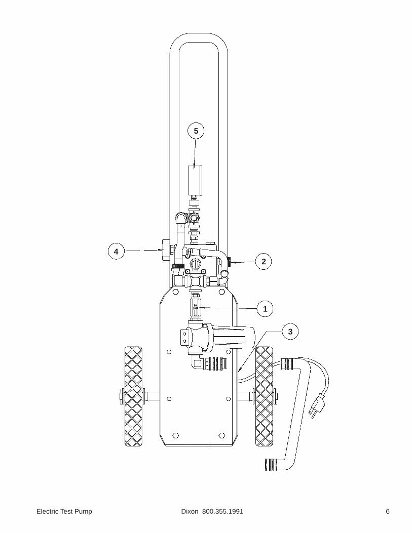
6. Open water inlet valve (1 - see drawing on page 6) to fill test specimen (hose)
7. Fill test sample with water. Vent all air from test sample by keeping the bleed-off valve elevated until a solid stream of water (no bubbles) is coming out of the bleed-off valve.
8. Close the bleed-off valve at this point. Recommended bleed-off valve 3,000 psi minimum.
9. Turn pressure control knob (2 -see drawing on page 6). Pressure knob located at right hand side of pump.
10. Start pump (3 - see drawing on page 6). Switch is located on the same side of the pump as the pressue control knob.
Warning!
Do not turn off water supply once test sample has been filled with water
5Electric Test Pump Dixon 800.355.1991
11. Turn pressure control knob (2 - see drawing on page 6) clockwise until desired test pressure is shown on liquid filled pressure gauge (5 - see drawing on page 6).
12. Hold test pressure until test duration requirement is met.
13. Turn pressure control knob (2 - see drawing on page 6) off (counter clockwise).
14. Turn off pump (3 - see drawing on page 6). This unit has a manual pressure relief knob (black knob - 4 - see drawing on page 6) with two lugs that is located on the opposite side of the
pressure control knob. To release pressure turn this knob so that the lugs are in the 12 O'clock and 6 O'clock positions. To generate pressure the lugs of this knob must be in the 3 O'clock and 9 O'clock positions.
16. Turn off water inlet valve (1 - see drawing on page 6).
17. Open bleed-off valve to release remaining pressure inside test specimen (hose).
18. Disconnect test sample from intermediate hose.
19. Drain water from test sample.
CAUTION!
When relieving the pressure and draining the test sample, many gallons of water may be released on the floor or ground. Use all precautions necessary to ensure that no one slips
or falls as a result of this water being on the floor or ground.
6Electric Test Pump Dixon 800.355.1991
5
42
1
3
7Electric Test Pump Dixon 800.355.1991
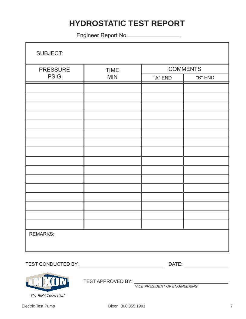
HYDROSTATIC TEST REPORTEngineer Report No.
PRESSUREPSIG
TIMEMIN
COMMENTS"A" END "B" END
TEST CONDUCTED BY: DATE:
TEST APPROVED BY:VICE PRESIDENT OF ENGINEERING
SUBJECT:
REMARKS:
8Electric Test Pump Dixon 800.355.1991
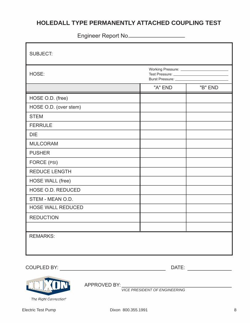
HOLEDALL TYPE PERMANENTLY ATTACHED COUPLING TEST
Engineer Report No.
COUPLED BY: DATE:
APPROVED BY:VICE PRESIDENT OF ENGINEERING
HOSE O.D. (free)
"B" END
SUBJECT:
REMARKS:
HOSE:
"A" END
Working Pressure:Test Pressure:Burst Pressure:
HOSE O.D. (over stem)
STEM
FERRULE
DIE
MULCORAM
PUSHER
FORCE (PSI)
REDUCE LENGTH
HOSE WALL (free)
HOSE O.D. REDUCED
STEM - MEAN O.D.HOSE WALL REDUCED
REDUCTION
9Electric Test Pump Dixon 800.355.1991
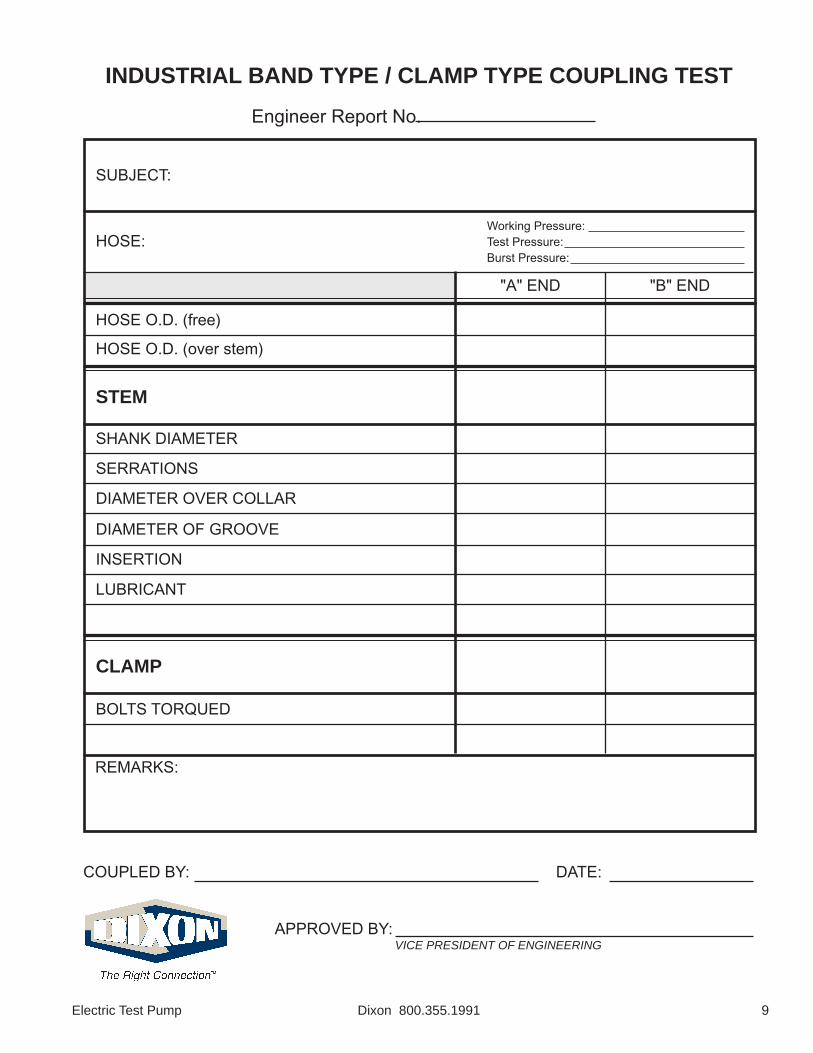
INDUSTRIAL BAND TYPE / CLAMP TYPE COUPLING TESTEngineer Report No.
COUPLED BY: DATE:
APPROVED BY:VICE PRESIDENT OF ENGINEERING
HOSE O.D. (free)
"B" END
SUBJECT:
REMARKS:
HOSE:
"A" END
Working Pressure:Test Pressure:Burst Pressure:
HOSE O.D. (over stem)
STEM
SHANK DIAMETER
SERRATIONS
DIAMETER OVER COLLAR
DIAMETER OF GROOVE
INSERTION
LUBRICANT
CLAMP
BOLTS TORQUED