Embed Size (px)
Citation preview

Qurayyah CCPP ProjectQurayyah CCPP Project Fail Free Commissioning
Control Valve(Fisher HC6010)
EPC) Commissioning Management Team
Page index
1. POSITIONER SPECIFICATION
2. POSITIONER AND ACTUATOR AIR FLOW2. POSITIONER AND ACTUATOR AIR FLOW
3. POSITIONER ATTACHMENT
4 SIGNAL LINE CONNECTION4. SIGNAL LINE CONNECTION
5. CALIBRATION PROCEDURE
6. MANUAL OPERATION
7.CONTROL VALVE LIMIT SWITCHES
8.ALARM AND STATUS
1
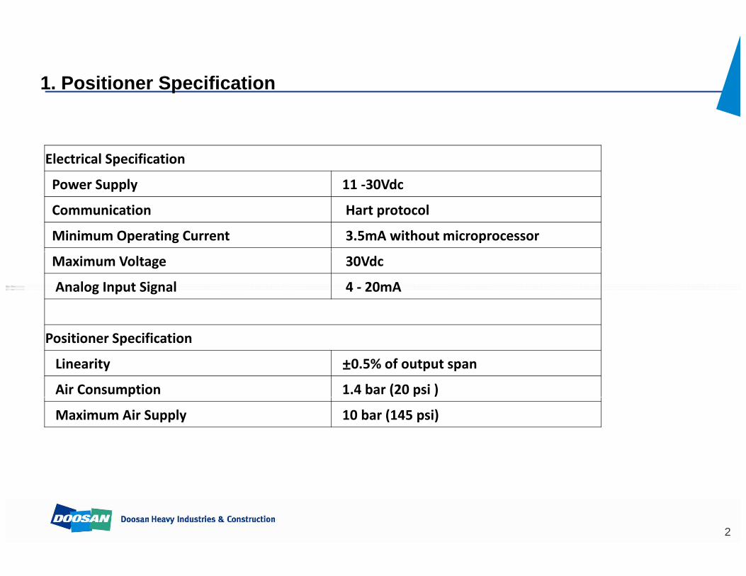
1. Positioner Specification
Electrical Specification
l dPower Supply 11 ‐30Vdc
Communication Hart protocol
Minimum Operating Current 3.5mA without microprocessor
Maximum Voltage 30Vdc
Analog Input Signal 4 ‐ 20mA
Positioner Specification
Linearity ±0.5% of output spanAir Consumption 1.4 bar (20 psi )
Maximum Air Supply 10 bar (145 psi)
2
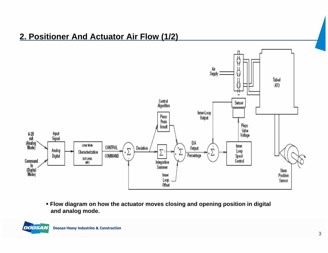
2. Positioner And Actuator Air Flow (1/2)
Flow diagram on how the actuator moves closing and opening position in digital g g p g p gand analog mode.
3
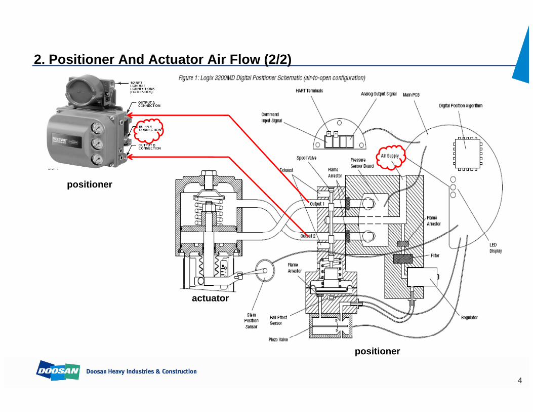
2. Positioner And Actuator Air Flow (2/2)
positioner
actuator
positioner
4
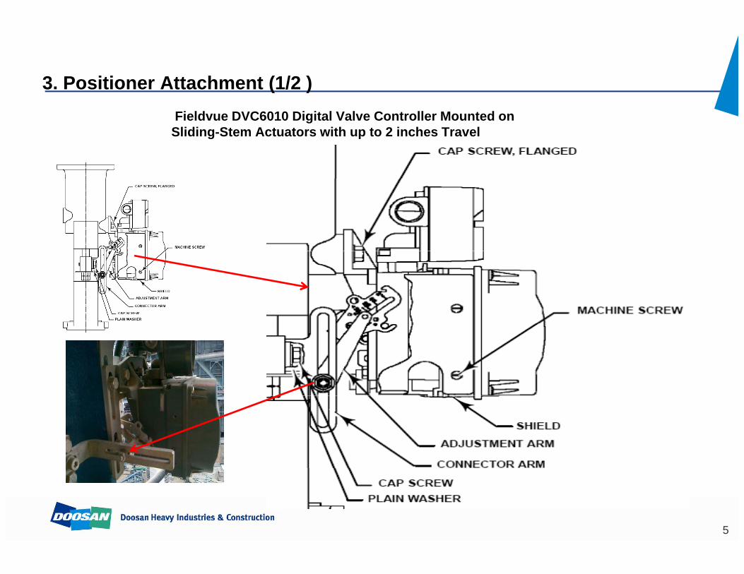
3. Positioner Attachment (1/2 )Fieldvue DVC6010 Digital Valve Controller Mounted on Sliding-Stem Actuators with up to 2 inches Travel
5

3. Positioner Attachment (2/2)
• Air to Open Actuator1. Insert the alignment pin in the hole marked A2. The feedback arm rotates counterclockwise, from A to B as air pressure to
the casing or lower cylinder increases.g y
• Air to Close Actuator1. Insert the alignment pin in the hole marked B2. The feedback arm rotates clockwise from B to A as air pressure to the
casing or upper cylinder increases
6
casing or upper cylinder increases.
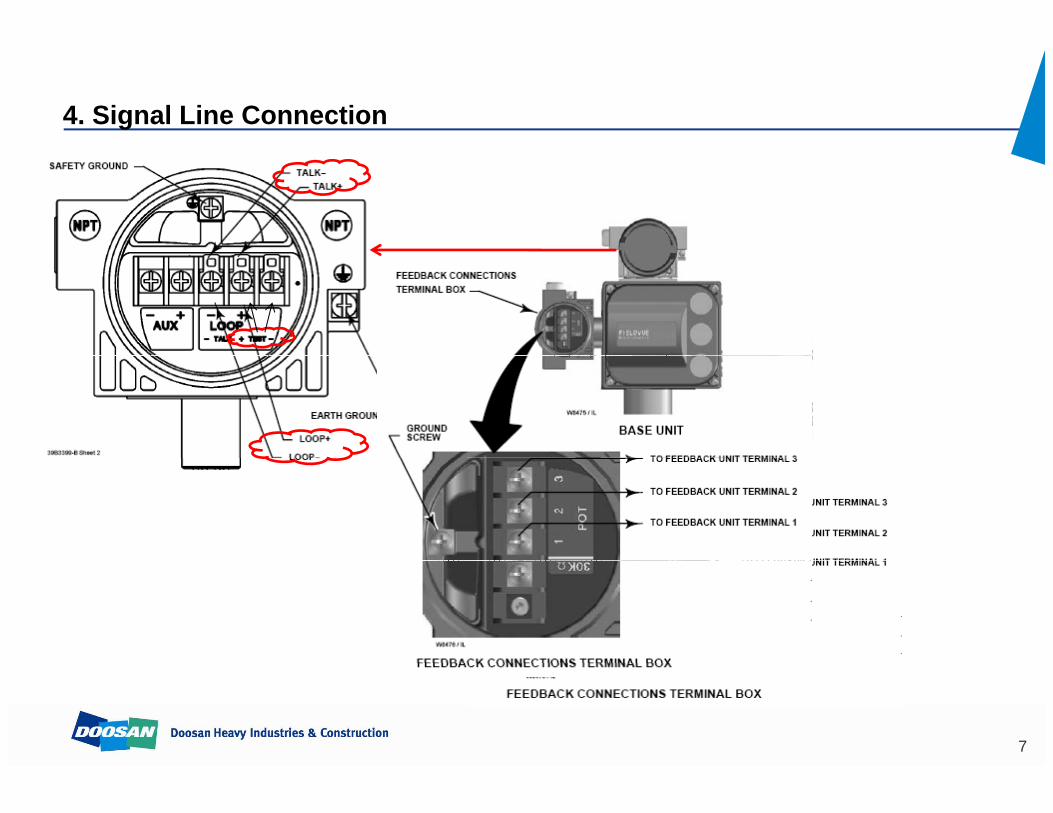
4. Signal Line Connection
7
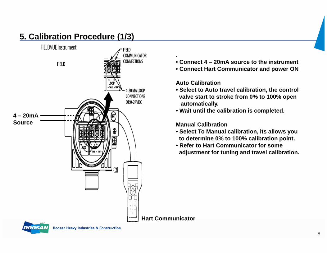
5. Calibration Procedure (1/3)
.• Connect 4 – 20mA source to the instrument• Connect Hart Communicator and power ON
Auto Calibration• Select to Auto travel calibration, the controlvalve start to stroke from 0% to 100% openautomatically.
• Wait until the calibration is completed• Wait until the calibration is completed.
Manual Calibration• Select To Manual calibration, its allows you to determine 0% to 100% calibration point.
4 – 20mASource
• Refer to Hart Communicator for some adjustment for tuning and travel calibration.
Hart Communicator
8
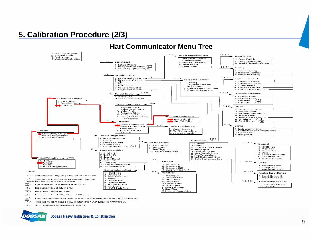
5. Calibration Procedure (2/3)H t C i t M THart Communicator Menu Tree
9
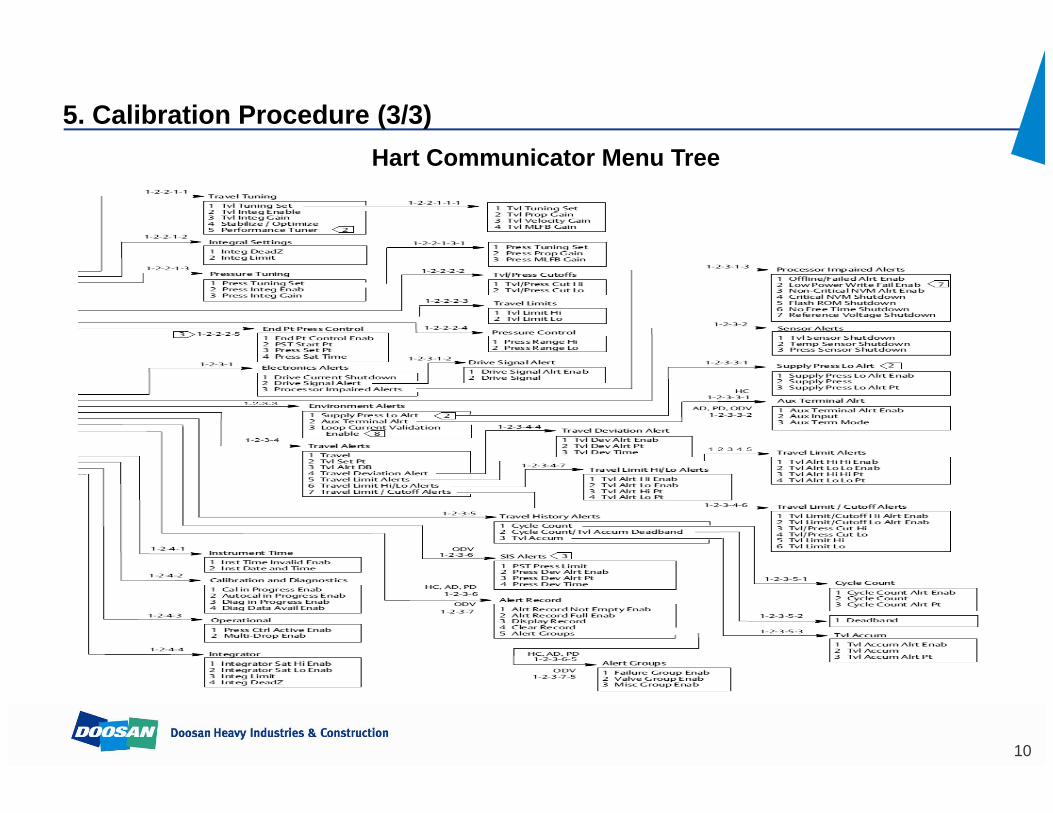
5. Calibration Procedure (3/3)H t C i t M THart Communicator Menu Tree
10
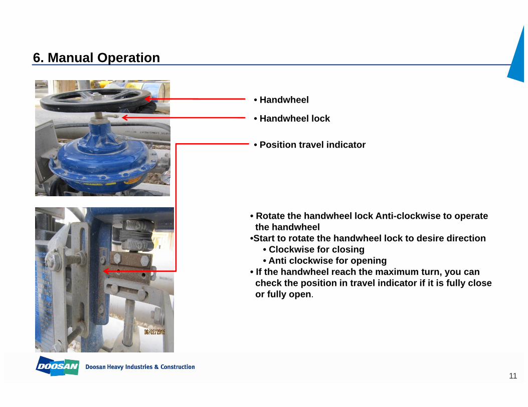
6. Manual Operation
• Handwheel
• Handwheel lock
• Position travel indicator
• Rotate the handwheel lock Anti-clockwise to operatethe handwheelthe handwheel
•Start to rotate the handwheel lock to desire direction• Clockwise for closing• Anti clockwise for opening
• If the handwheel reach the maximum turn, you can h k th iti i t l i di t if it i f ll lcheck the position in travel indicator if it is fully close
or fully open.
11
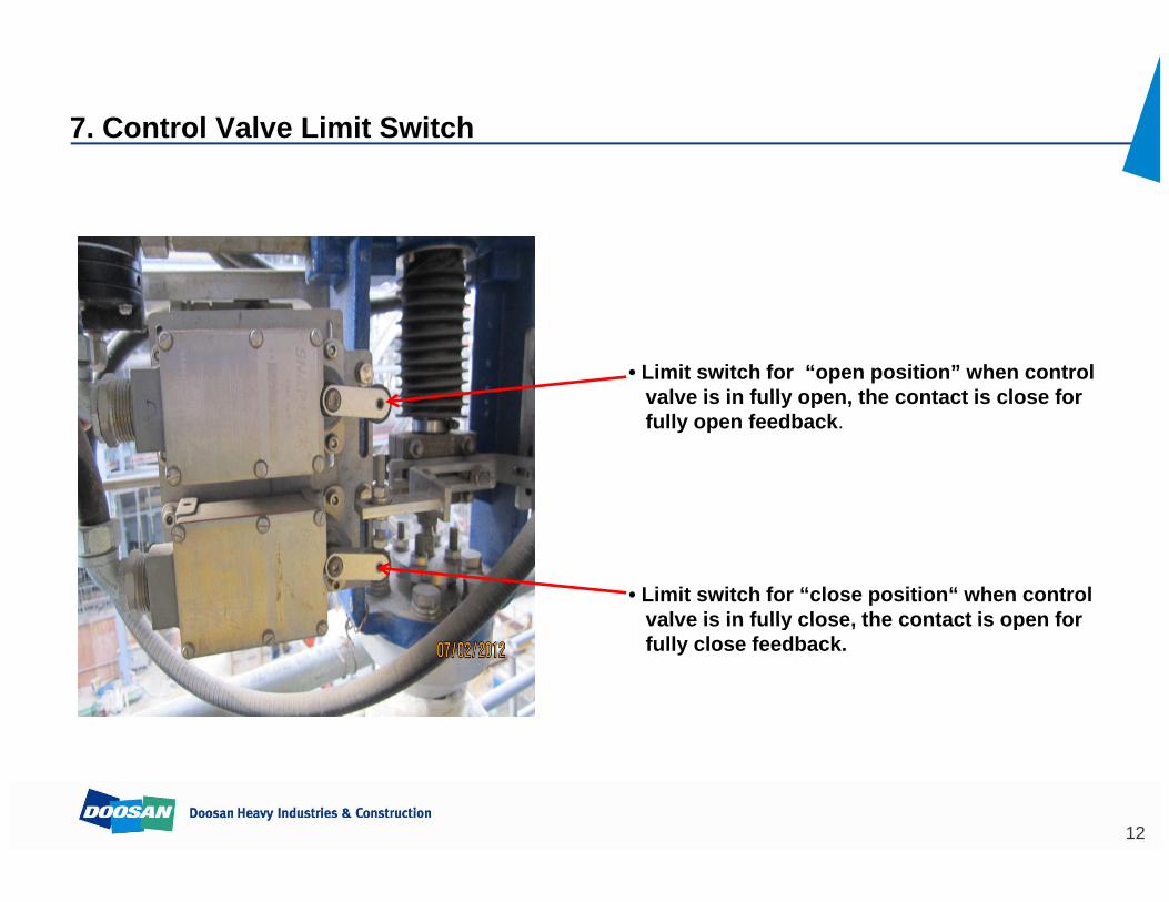
7. Control Valve Limit Switch
• Limit switch for “open position” when controlvalve is in fully open the contact is close forvalve is in fully open, the contact is close forfully open feedback.
• Limit switch for “close position“ when controlvalve is in fully close the contact is open forvalve is in fully close, the contact is open forfully close feedback.
12
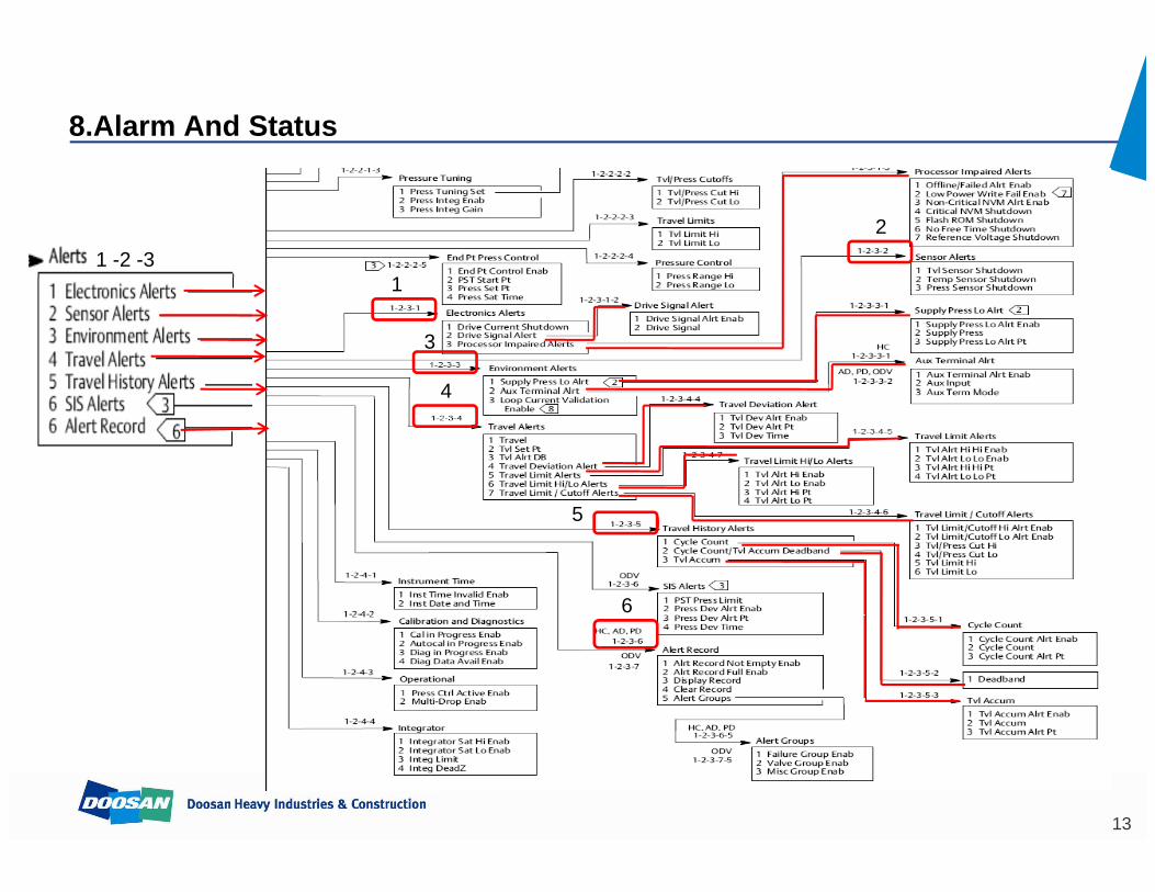
8.Alarm And Status
1
21 -2 -3
1
3
44
5
6
13