Embed Size (px)
Citation preview

1
PROBE DIAGNOSTICS OF RF PLASMAS
FOR MATERIAL PROCESSING
V. A. Godyak
RF Plasma Consulting and University of Michigan
Brookline, MA 02446, USA
Fundamental Processes, Modeling and Diagnostics
of Low-Temperature Plasmas
Preconference Tutorials at GEC 2013, Princeton, NJ, September 28-29, 2013
“There is no plasma diagnostics method other than probe
diagnostics where the danger of incorrect measurements
and erroneous interpretation of results are so great.”
L. Schott, in Plasma Diagnostics, ed.
W. Lochte-Holtgreven. Amsterdam,1968
45 years later when plasma and its diagnostics
got more complex, that is at least as much true.

3
Langmuir probe diagnostics
• Langmuir probe is a powerful diagnostic tool for low pressure gas discharge
plasmas
• Practically all today knowledge on gas discharge was obtained with plasma
spectroscopy and Langmuir probes (both imply a Maxwellian EEDF)
• The ability of measurement of local plasma parameters and the electron energy
distribution function (EEDF) makes it unique among other diagnostics
• EEDF is the most informative, universal and complete characteristic of the
plasma electrons in any plasma
• Basic plasma parameters (N and Te) and rates of plasma-chemical processes can
be found as appropriate integrals of the measured (non-Maxwellian) EEDF

4
Non Equilibrium Gas Discharge Plasmas Diagnostics
Gas pressure, p - between fraction and hundreds mTorr
Mean electron energy, <ε> – between fraction and tens eV
Plasma density, N – between 106-1014 cm-3
In plasmas, electrons are often not in equilibrium with RF field, nor
with ions and atoms, nor within its own ensemble, i.e. have a non-
Maxwellian EEDF with Te >> Ti, Tg
When we have no idea what is a real EEDF, we assume it to be a
Maxwellian. Indeed, in low pressure gas discharges, it is always non-
Maxwellian
Classical Langmuir probe diagnostics (based on electron and ion
current), as well as many other diagnostics, assume a Maxwellian
EEDF. Found this way plasma parameters and especially rates of
inelastic processes can be in dramatic disagreement with their true
values

5
.)()(22
)()(
22
dfeV
m
eSd
FeV
m
eSI
eV
p
p
eV
p
e
Plasma density and effective electron temperature are:
Langmuir formula and Druyvesteyn method
Similarly, all plasma parameters (Tesk, λD, JB) and rates of plasma-chemical processes
(νea, νee, ν*, νi, ….) can be found as appropriate integrals of the measured EEPF.
Druyvesteyn formula
I. Langmuir, Gen.
Electr. Rev. 25, 1924
M. J. Druyvesteyn, Z.
Phys. 64, 781, 1930
6
What makes a good EEDF measurement?
• EEDF has to resolve the tail electrons (ε > ε*) responsible for excitation,
ionization and electron escape to the wall, as well as the low energy electrons
(ε < 2Te) accounting for the majority of electrons
• Due to error augmentation inherent to differentiation procedure, small (invisible)
inaccuracy in Ip(V) can bring enormous distortion in the inferred EEDF
• It is important to realize the source of the possible errors and to be able to
mitigate them
• The sources of the errors are well elucidated in the literature, but are insistently
ignored in the majority of published papers on EEDF measurement with home
made and commercial probe system.
• The constrains for the Druyvesteyn method applicability coincide with those for
the classical Langmuir method
• There are techniques for EEDF measurement in collisional, magnetized and
anisotropic plasmas (not considered here)
See review by Godyak and Demidov, J. Phys. D: Appl. Phys. 44, 233001, 2011

7
Problems in probe measurements and their mitigations.
1. Probe size: a [ln(πl/4a)], b, λD << le and Ip << Id, Ir, Iz
Ir ≈ IB = ScheNsuB, is the current emission of the counter electrode
uB = (Te/M)1/2, Iz = eΓe is the current corresponding to generation rate
of electrons with energy ε in the volume defined by the chamber
characteristic size Λ, or by the electron energy relaxation length λε
(SpN0/SchNs)(M/2πm)1/2 << 1
a = 38 μm
b = 175 μm a b V. Godyak et al,
PSST 1, 179, 1992

8
2a = 0.1 mm, 2b =1 mm, 2c = 6 mm
Probe constructions
P1 P2
V. Godyak et al,
PSST 1, 179, 1992
Plasma Sensors Probe System®
www.plasmasensors.com
V. Godyak et al,
PSST 11, 525, 2002
c
a b
The most popular bad probe design
b

9
RF plasma potential
Criterion for undistorted by the probe rf sheath voltage EEPF
measurement is known for over 30 years
V. Godyak and S. Oks, Sov. Phys.
-Tech. Phys. 24, 784, 1979
Vshrf ≤ (0.3-0.5)Te/e
A presence of a filter in the probe circuit does not guarantee undistorted
EEPF measurement. To do the job, the filter has to satisfy the following
condition for all relevant harmonics:
Zf ≥ (2-3)ZpreVplrf /Te
For filter design one needs to know (measure, calculate) Vplrf and
minimize Zpr
Zpr is the impedance between the probe and plasma (Zpr is defined by its sheath capacitance at floating
potential, Zf is the filter impedance, Vplrf is the rf plasma potential reference to ground, Vshrf is the rf
Voltage across the probe sheath, and T is electron temperature

10
Filter design procedure
The filter has to be designed after the
measurements of the rf plasma potential
spectrum! V. Godyak et al,
PSST 1, 179, 1992
CCP at 13.65 MHz, V = 100 V

11
Probe measurement circuit for EEPF
measurement in Ar CCP, incorporating, dc
voltage and low frequency noise
suppressions, rf compensation and rf filter
dc resistance compensation with I/V -
converter having a negative input
resistance (gyrator)
1- distorted
w/o filter
2- undistorted
V. Godyak et al,
PSST 1, 179, 1992

12
Probe circuit resistance Rc (the most common problem)
Rc = Rext + Rpsh + Rint
V. Godyak et al,
PSST 11, 525, 2002
The voltage V applied to the probe is distributed along the
probe circuit elements (Rext, Rpsh, Rint), thus, Vpsh< V !

13
EEPF Druyvesteynization due to circuit resistance Rc
δ = Rc/Rpmin Rpmin= Te/eIesat
Error in EEPF less than 3% requires Rc/Rpmin < 0.01 !
Rc and LF noise compensation
Maxwellian
Druyvesteyn
V. Godyak et al,
PSST 11, 525, 1002

14
Specifics of probe diagnostics in plasma processing chambers
• High plasma RF and dc voltage with wide RF spectrum (multi-frequency)
• High low-frequency noise typical for molecular and electronegative gases
• Bead electrical contact between plasma and grounded chamber
• Probe contamination with reaction products
Probe measurements in processing RF plasma are usually distorted. The
problem is not recognized when one just measures the probe I/V characteristic,
since distorted and undistorted probe characteristics look very similar. But the
problem becomes apparent after differentiation the I/V characteristic to get the
EEDF
REMEDIES:
• Feedback with reference probe to compensate Rc and LF noise
• Continuous probe cleaning with ion bombardment, electron heating together
with fast probe scan (mS)
• Adequate RF filtering for all relevant RF plasma frequencies and potentials

15
Reliable high quality EEDF and plasma parameter measurements in research and industrial CW and pulsed plasmas
in noble and reactive gases, having high DC (up to 1 kV) and RF voltages and multi-frequency drive (2-200 MHz)
User friendly interface, automatic ranging, real time processing, display, and data output of the plasma parameters
High energy resolution and dynamic range of MFPA enables precise analyses of low and high energy parts of EEDF,
correspondingly representing the bulk plasma behavior and the electron impacted inelastic processes
MFPA eliminates errors common to existing commercial probe systems, which are caused by the probe work function
variation, the plasma potential drift, and the plasma potential bias by the probe current
Control of peripheral devices such as motor drives, electrostatic energy analyzers, probe array multiplexors can be
seamlessly plugged into MFPA software routine. The MFPA real-time output data can be used for the endpoint detection
and deposition rate assessment
MFPA employs automatic probe cleaning by the ion bombardment and heats it to a preset temperature (500 -1500°C)
with the electron current
MFPA allows for measurements of the ion current with probes that are contaminated or chambers coated with non-
conductive materials
Plasma Sensors Probe System MFPA
The aforementioned problems has been addressed in MFPA instruments

16
MFPA Display
17
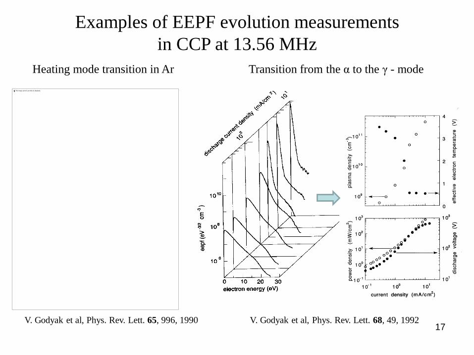
Examples of EEPF evolution measurements
in CCP at 13.56 MHz
Heating mode transition in Ar Transition from the α to the γ - mode
V. Godyak et al, Phys. Rev. Lett. 68, 49, 1992
V. Godyak et al, Phys. Rev. Lett. 65, 996, 1990

18
106
107
108
109
1010
1011
1012
1013
0 10 20 30 40 50
50
50W
50
50W
.3mT50W
eepf (e
V -
3/2
cm
-3 )
electron energy (eV)
110100
300 mT
0.3 i
6.78 MHz, 50 W
*
1010
1011
1012
1013
0
2
4
6
8
10
10-1
100
101
102
103
pla
sm
a d
en
sity (
cm
-3)
effe
ctive
ele
ctr
on
te
mp
era
ture
(e
V)
gas pressure (mT)
6.78 MHz, 50 W
Example of EEPF measurement in argon ICP with a
probe having adequate Rc and RF noise compensation
The maximal argon pressure, was
limited by the chamber surface
when Iich > Iesat
V. Godyak et al,
PSST 11, 525, 2002
V. Godyak et al,
PSST 11, 525, 2002
DC plasma
potential

Examples of EEPF measurements in Ar ICP
Frequency dependence Power dependence
W
In high density plasmas, the EEPF at low energy must be Maxwellian 19
V. Godyak et al, PSST 11, 525, 1002 V. Godyak & V. Kolobov, Phys. Rev. Lett., 81, 369, 1998

20
Time resolved EEPF measurements
EEPF measured in afterglow stage of ICP with internal ferrite core inductor
109
1010
1011
1012
0 5 10 15
ee
pf
(ev
-3/2
cm
-3 )
electron energy (eV)
Ar, 30 mT, 50 W; off cycle
Ton
= 2 s
Toff
= 20 s
t = 2.8 s 3.6 4.4 6.8 9.2 12.4 18.8
0.1
1
1 10 100 1000
ele
ctr
ron
te
mpera
ture
(eV
)
time (s)
300
100
30
3 mT10
Ar, CW 100 W
p Te
(mT) (eV)
3.0 6.510 4.230 3.1 100 2.1300 1.5
V. Godyak & B. Alexandrovich,
XXVII ICPIG, vol. 1, p. 221, 2005
Room temperature
Repetitive
Single
pulse

21
Argon, 20 mTorr
Hiden: max = 7-11 eV
Argon, 20 mTorr
Pl. Sen.: max = 15-22 eV
Distorted @ low energy and lost information @ high
energy
Maxwellization
νee ∞ NTe-3/2
“Druyvesteynization”
Comparison of EEPF measured
with different commercial probe
stations, Espion of Hiden and
VGPS of Plasma Sensors.
At maximal discharge power of
2 kW, N ≈ 1012 cm-3, due to e-e
collisions, the EEPF @ ε < ε*
has to be a Maxwellian one.
“Druyvesteynization” effect is
found in many publications of
EEDF measurements made with
home-made and commercial
probe systems.
EEDF measurements with commercial probe systems
V. Godyak et al, GEC 2009, Saratoga
Springs, NY, USA
ε* Noise
Noise
22
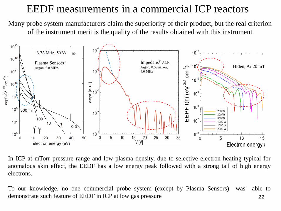
In ICP at mTorr pressure range and low plasma density, due to selective electron heating typical for
anomalous skin effect, the EEDF has a low energy peak followed with a strong tail of high energy
electrons.
To our knowledge, no one commercial probe system (except by Plasma Sensors) was able to
demonstrate such feature of EEDF in ICP at low gas pressure
Many probe system manufacturers claim the superiority of their product, but the real criterion
of the instrument merit is the quality of the results obtained with this instrument
Impedans® ALP,
Argon, 0.59 mTorr,
4.0 MHz
®
Plasma Sensors®
Argon, 6.8 MHz,
EEDF measurements in a commercial ICP reactors
Hiden, Ar 20 mT

23
EEPF measurements in plasma reactors
Wide specter and large amplitude of rf plasma potential and high rate of probe
contamination are the major problems making even classic Langmuir probe diagnostic impossible
EEPF measured in ECR array
reactor, Ar/SiF4 at10 mTorr with
crystalline silicon deposition.
Ecole Polytechnique, France
EEPF measured in commercial two-
inductor ICP etcher with different
processing mixtures at 15 mTorr.
Mattson Technology, USA
EEPF measured in ICP reactor,
Ar and Ar/H2 at different argon
pressure and hydrogen addition.
University of Maryland, USA
Concluding Remarks
• Today, plasma simulation codes are practically main tool for study plasma in industrial
plasma sources. These codes applied to plasma with complicated processing gas mixture
are missing many cross sections for variety of plasma-chemical reactions.
• They also are missing effects of nonlocal and nonlinear plasma electrodynamics that has
been proved are important and even dominant in rf plasmas at low gas pressure.
• In such situation, a reliable measurement of EEDF and plasma parameters would give a
valuable experimental data for understanding variety of electrodynamics, transport and
kinetic process in such plasmas and for validation of existing theoretical models and
numerical codes.
For more complete information see:
1. V. Godyak, Measuring EEDF in Gas Discharge Plasmas, review in NATO ASI Series, E. Appl. Sci.,
V. 176, Plasma Surface Interaction and Processing of Materials, pp. 95-134, Kluwer, Acad. Publisher,
1990
2. V. Godyak and V. Demidov, Probe Measuring of Electron Energy Distribution in Plasmas: What Can
We Measure and How Can We Achieve Reliable Results?, J. Phys. D: Appl. Phys. 44, 233001, 2011
3. Plasma Sensors Probe System, www.plasmasensors.com, GEC2013 exhibition PLASMA SENSORS