Embed Size (px)
Citation preview

This article was downloaded by: [Wageningen UR Library]On: 05 August 2014, At: 16:50Publisher: Taylor & FrancisInforma Ltd Registered in England and Wales Registered Number: 1072954 Registeredoffice: Mortimer House, 37-41 Mortimer Street, London W1T 3JH, UK
Journal of Earthquake EngineeringPublication details, including instructions for authors andsubscription information:http://www.tandfonline.com/loi/ueqe20
Probabilistic Performance Assessmentof Retrofitted Skewed Multi SpanContinuous Concrete I-girder BridgesBehzad Zakeria & Gholamreza Ghodrati Amiriaa Department of Civil Engineering, Iran University of Science andTechnology, Tehran, IranAccepted author version posted online: 20 May 2014.Publishedonline: 01 Jul 2014.
To cite this article: Behzad Zakeri & Gholamreza Ghodrati Amiri (2014) Probabilistic PerformanceAssessment of Retrofitted Skewed Multi Span Continuous Concrete I-girder Bridges, Journal ofEarthquake Engineering, 18:6, 945-963, DOI: 10.1080/13632469.2014.916241
To link to this article: http://dx.doi.org/10.1080/13632469.2014.916241
PLEASE SCROLL DOWN FOR ARTICLE
Taylor & Francis makes every effort to ensure the accuracy of all the information (the“Content”) contained in the publications on our platform. However, Taylor & Francis,our agents, and our licensors make no representations or warranties whatsoever as tothe accuracy, completeness, or suitability for any purpose of the Content. Any opinionsand views expressed in this publication are the opinions and views of the authors,and are not the views of or endorsed by Taylor & Francis. The accuracy of the Contentshould not be relied upon and should be independently verified with primary sourcesof information. Taylor and Francis shall not be liable for any losses, actions, claims,proceedings, demands, costs, expenses, damages, and other liabilities whatsoever orhowsoever caused arising directly or indirectly in connection with, in relation to or arisingout of the use of the Content.
This article may be used for research, teaching, and private study purposes. Anysubstantial or systematic reproduction, redistribution, reselling, loan, sub-licensing,systematic supply, or distribution in any form to anyone is expressly forbidden. Terms &Conditions of access and use can be found at http://www.tandfonline.com/page/terms-and-conditions
Journal of Earthquake Engineering, 18:945–963, 2014Copyright © A. S. ElnashaiISSN: 1363-2469 print / 1559-808X onlineDOI: 10.1080/13632469.2014.916241
Probabilistic Performance Assessment of RetrofittedSkewed Multi Span Continuous Concrete
I-girder Bridges
BEHZAD ZAKERI and GHOLAMREZA GHODRATI AMIRI
Department of Civil Engineering, Iran University of Science and Technology,Tehran, Iran
The unique dynamic response of skewed bridges causes them to experience more noticeable damagecompared to straight bridges during seismic events. The effectiveness of different retrofit strategieson the fragility of skewed bridges can change with the skew angle. This article assesses the impact ofskew angle and various retrofit strategies on the fragility of multi span continuous concrete I-girderbridges. The results indicate that the level of effectiveness of a retrofit strategy is highly dependenton the skew angle and damage state of interest and an appropriate retrofit strategy should be chosenbased on the vulnerability of the components.
Keywords Skewed Bridges; Vulnerability; Retrofit Strategies; Fragility; Continuous ConcreteGirder Bridge
1. Introduction
Skewed bridges with inadequate seismic detailing have experienced considerable dam-age during recent earthquakes due to their inherent irregularity and complicated dynamicresponse. Many researchers have carried out studies on the modeling, seismic responseand vulnerability of skewed bridges. A rigid body model for the bridge superstructure wasimplemented by Maragakis and Jennings [1987] and they concluded that rotation of thedeck occurs due to skewness and pounding between the deck and the abutment. Parametricstudies exploring the effect of the skew angle, aspect ratios, and stiffness eccentricity onthe seismic response of bridges were carried out by Meng et al. [2001]. In their study, theeffect of pounding between the abutment and the bridge deck was neglected. An approxi-mate method to estimate the dynamic response of skew bridges was proposed by Kalantariand Amajadian [2010]. Shamsabadi et al. [2006] and Schroeder [2006] found that deckunseating; shear and flexural failure of columns, abutment, and deck rotation are the mostrelevant failure modes for skewed bridges. Dimitrakopoulos [2011] developed a theoreticalformulation that captured the effect of pounding between a rigid deck and an abutment.It was concluded in the study that in order to assess the rotation and translation of skewedbridge decks, the geometry of the span (span/width ratio) and the friction should be con-sidered, in addition to the skew angle. Kwon and Jeong [2013] conducted a comprehensivestudy for skewed bridges by exploring the effect of vertical ground motions, skew angle andaspect ratio on the seismic displacement demand of skewed bridges. Their results revealed
Received 9 October 2013; accepted 27 March 2014.Address correspondence to Behzad Zakeri, Iran University of Science and Technology, PO Box 16765-163,
Narmak, Tehran 16846, Iran. E-mail: [email protected] versions of one or more of the figures in the article can be found online at www.tandfonline.com/ueqe.
945
Dow
nloa
ded
by [
Wag
enin
gen
UR
Lib
rary
] at
16:
50 0
5 A
ugus
t 201
4
946 B. Zakeri and G. G. Amiri
that the skew angle increases the rotational demand of the deck, particularly when subjectedto near-fault ground motions.
In order to decrease bridges’ vulnerabilities during seismic excitations, various retrofitprograms have been developed after the San Fernando and Northridge earthquakes in theUnited States (US), particularly on the West Coast [Robinson et al., 1979; Robert, 1998;Priestly and Seible, 1991; FHWA, 2006]. Different retrofit measures have been recom-mended or implemented by various researchers based on the component vulnerabilities andbridge classes. The effect of steel jackets on the flexural and shear capacity of RC columnshas been explored by Priestley et al. [1992]. The effect of restrainer cables on mitigat-ing deck unseating and decreasing the potential of pounding between adjacent decks hasbeen investigated by many researchers [Saiidi et al., 1996; Kawashima and Shoji, 2000;DesRoches et al., 2003; Watanabe and Kawashima, 2004]. All the findings show that theaccurate design of restrainers can decrease the potential of pounding and deck unseating,particularly in skewed bridges. Seismic retrofit practice in the Central and SoutheasternUnited States (CSUS) [Wright et al., 2011] has clarified the effect of shear keys on mitigat-ing deck unseating and avoiding the need for additional force transfer to the substructurecomponents.
Deterministic studies have been carried out by different researchers on the effect ofretrofit measures on the seismic behavior of skewed bridges. These include the effect of linkslabs on the seismic behavior of simply-supported bridges [Sevgili and Cancer, 2009], theeffect of three configurations of restrainer cables on the dynamic behavior and potential fordeck unseating in skewed simply supported concrete bridges [Watanabe and Kawashima,2004] and the effect of friction rubber bearings on the seismic behavior of skewed simply-supported bridges [Liu et al., 2008]. All the deterministic analyses neglected uncertaintiesin the retrofit assessment, such as those that stem from the seismic hazard or the bridgeresponse and performance modeling.
Several fragility analyses have been conducted for non-retrofitted and retrofittedbridges. Although most of the studies have developed fragility curves for non retrofittedbridges [Shinozuka, 1998; Hwang et al., 2000; Choi et al., 2004; Mackie and Stojadinovic,2004], a few of these studies have focused on retrofitted bridges. Fragility analyses for nonskew typical Californian box girder bridges, retrofitted with steel jackets and elastomericisolation bearings, were conducted by Yang et al. [2009]. The results of this study show thatusing elastomeric isolation bearings can considerably reduce the bridge fragility across alldamage states in comparison to using column steel jackets. Padgett and DesRoches [2009]developed fragility curves for retrofitted non skew typical classes of multispan bridges inCSUS. They concluded that the effectiveness of each retrofit measure is highly dependenton the bridge type and damage state. The effect of isolation on the fragility of the bearings,piers and bridge system has been explored by Zhang and Hou [2008]. According to theirfindings, the mechanical properties of isolation devices have a considerable effect on thecomponent and bridge system fragilities. The effect of elastomeric bearings, lead-rubberbearings, viscous dampers, and jacketing with carbon fibers on the fragility of multispancontinuous steel bridges in New York was investigated by Agrawal et al. [2011]. They con-cluded that all the aforementioned retrofit measures are effective in reducing the bridgefragility. The impact of skewness on the effectiveness of retrofit was not considered bythese researchers. The effect of skew angle on the fragility of retrofitted concrete boxgirder bridges has been explored by Zakeri et al. [2013]. According to their findings, skewangle has noticeable impact on the effectiveness of retrofit measures. Despite such effortsto explore the effect of retrofit measures on the performance of bridges probabilistically;a comprehensive study on the effect of skewness on the fragility of retrofitted multi spancontinuous concrete I-girder (MSCC-IG) bridges is needed.
Dow
nloa
ded
by [
Wag
enin
gen
UR
Lib
rary
] at
16:
50 0
5 A
ugus
t 201
4

Performance Assessment of Retrofitted Skewed Concrete Bridges 947
This article explores the effect of common retrofit strategies such as steel jacketing,restrainer cables, shear keys, seat extenders and a combination of these measures on thefragility of skewed MSCC-IG bridges at both component and system levels. Componentand system fragility curves are developed for the various retrofit strategies of the skewedbridges to compare the effect of both the skew angle and retrofit strategy on the bridgefragility. The probabilistic analysis conducted in this article considers different sourcesof uncertainty such as bridge modeling parameters, ground motion characteristics, andgeometric parameters.
2. Analytical Fragility Methodology, Case Study Bridge Class, and RetrofitStrategies
Bridge fragility curves are powerful tools that provide a quantitative measure of the vulner-ability of bridges in their as-built or retrofitted condition at different performance levels,referred to as damage states in this study. The fragility curves used in this study for slight,moderate, extensive, and complete damage states will be discussed in greater detail in Sec.2.1. Multi span continuous concrete I-girder bridges are chosen in this study for the fragilityanalysis. A range of common retrofit strategies are implemented in this paper to evaluatetheir effect as well as the effect of the skew angle on the fragility of this class of bridge.
2.1. Seismic Fragility Methodology for Retrofitted Bridge Classes
Seismic fragility curves for retrofitted bridges are conditional probabilistic statements ofdamage that offer a means to compare the effect of different retrofit strategies on the poten-tial bridge damage. An overview of the fragility methodology is presented herein, whilethe detailed approach can be found elsewhere [Padgett and DesRoches, 2008]. Followingfrom the basic definition of fragility, as presented in Eq. (1), the fragility is the probabilityof the seismic response or demand (D) exceeding the limit state or structural capacity (C),given a level of hazard intensity measure (IM):
Pf = P {D ≥ C|IM} . (1)
Definition of the component capacities or limit states is a crucial step in the fragilityformulation [Ramanathan, 2012]. The major challenge is to be able to group compo-nents that have similar consequences at the system level in terms of functionality andrepair consequences. The estimation of capacities for bridge components (DC1–DC4) andthe overall bridge system (DS1–DS4) damage states, which are quantitative of compo-nent and bridge system performance, respectively, are developed based on Ramanathan[2012] and HAZUS-MH [FEMA, 2005]. Damage states of primary and secondary com-ponents (DC), detailed in Table 1, are aimed at achieving similar consequences in termsof bridge operation following an earthquake [Ramanathan, 2012]. Primary componentsinclude the columns and abutment seats and directly correspond to the system damagestates (DS1–DS4) and contribute equally to the system vulnerability across all damagestates. On the other hand, the secondary components correspond only to DS1 and DS2 sincetheir complete failure will not have as negative a consequence as failure of the primary com-ponents. Additional information regarding components and the concept of grouping theminto primary and secondary categories can be found elsewhere [Ramanathan, 2012].
Given that the damage state descriptions (Table 1) indicate system damage levelassignment in the event that any of the relevant component damage levels are exceeded,
Dow
nloa
ded
by [
Wag
enin
gen
UR
Lib
rary
] at
16:
50 0
5 A
ugus
t 201
4

948 B. Zakeri and G. G. Amiri
TABLE 1 Component and system-level limit states definitions consistent with Caltransqualitative damage states [Ramanatan, 2012]
Component Level Limit States
LimitStates
Caltrans Qualitative DamageStates
PrimaryComponents
SecondaryComponents
SystemLevelLimitStates
Slight Open to normal public traffic–No Restrictions
DC1 DC1 DS1
Moderate Open to limited public trafficspeed/weight/lanerestrictions
DC2 DC2 DS2
Extensive Emergency vehicles only –speed/weight/lanerestrictions
DC3 N/A DS3
Complete Closed (until shored/braced)– potential for collapse
DC4 N/A DS4
N/A=Not Applicable, Indicates that the secondary components do not contribute to the system levelspecified damage state.
the bridge system is considered as a series system. System fragility curves are derivedconsidering the correlations between components using the approach adopted by paststudies [Padgett, 2007; Padgett and DesRoches, 2008]. Therefore, based on the series sys-tem definition and primary or secondary component classification, the system fragility, orprobability of meeting or exceeding the system damage state j, is evaluated as follows:
P[DSj|IM] =
⎧⎪⎪⎨⎪⎪⎩
P
[N⋃
i = 1Eprimary_i
(DCj|IM
)]for j ≥ 3
P
[N⋃
i = 1Eprimary_i
(DCj|IM
)] + P
[M⋃
m = 1Esecondary_i
(DCj|IM
)]for j ≤ 2
(2)
where N indicates the total number of primary components, M is the total number of sec-ondary components, j ={1, 2, 3, 4} corresponding to the slight, moderate, extensive, andcomplete damage states. P[DSj|IM] is typically computed as the probability of the unionof eventsEi[DSj|IM], in which each of the ith bridge components reaches or exceeds the jth
damage state.In order to evaluate the failure probability of the components, a closed form solution
according to Nielson and DesRoches [2007] can be used. Lognormal distributions of thecomponent fragility are estimated in the form of:
P [DC|PGA] = �
(ln (PGA) − ln
(medcomp
)ζcomp
), (3)
where medcomp is the median value of the component fragility (in units of g PGA) and ζ comp
is the dispersion, or logarithmic standard deviation, of the component fragility.Component and system level fragility analyses require quantitative modeling of the
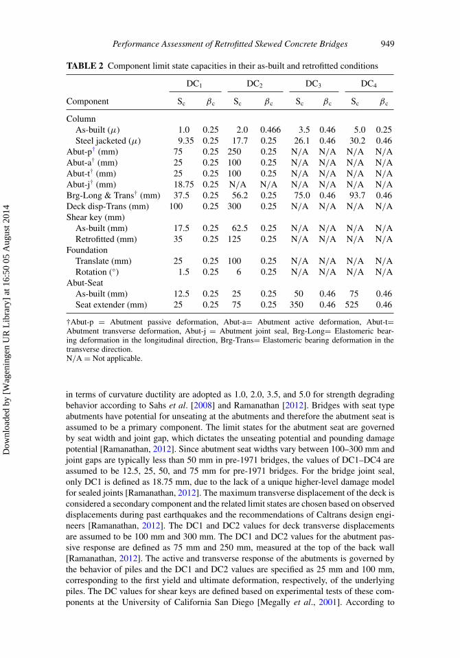
component capacities, as presented in Table 2. Bridge columns in their as-built conditionare assumed to have strength degrading behavior in pre-1971 eras. Their related limit states
Dow
nloa
ded
by [
Wag
enin
gen
UR
Lib
rary
] at
16:
50 0
5 A
ugus
t 201
4
Performance Assessment of Retrofitted Skewed Concrete Bridges 949
TABLE 2 Component limit state capacities in their as-built and retrofitted conditions
DC1 DC2 DC3 DC4
Component Sc βc Sc βc Sc βc Sc βc
ColumnAs-built (μ) 1.0 0.25 2.0 0.466 3.5 0.46 5.0 0.25Steel jacketed (μ) 9.35 0.25 17.7 0.25 26.1 0.46 30.2 0.46
Abut-p† (mm) 75 0.25 250 0.25 N/A N/A N/A N/AAbut-a† (mm) 25 0.25 100 0.25 N/A N/A N/A N/AAbut-t† (mm) 25 0.25 100 0.25 N/A N/A N/A N/AAbut-j† (mm) 18.75 0.25 N/A N/A N/A N/A N/A N/ABrg-Long & Trans† (mm) 37.5 0.25 56.2 0.25 75.0 0.46 93.7 0.46Deck disp-Trans (mm) 100 0.25 300 0.25 N/A N/A N/A N/AShear key (mm)
As-built (mm) 17.5 0.25 62.5 0.25 N/A N/A N/A N/ARetrofitted (mm) 35 0.25 125 0.25 N/A N/A N/A N/A
FoundationTranslate (mm) 25 0.25 100 0.25 N/A N/A N/A N/ARotation (◦) 1.5 0.25 6 0.25 N/A N/A N/A N/A
Abut-SeatAs-built (mm) 12.5 0.25 25 0.25 50 0.46 75 0.46Seat extender (mm) 25 0.25 75 0.25 350 0.46 525 0.46
†Abut-p = Abutment passive deformation, Abut-a= Abutment active deformation, Abut-t=Abutment transverse deformation, Abut-j = Abutment joint seal, Brg-Long= Elastomeric bear-ing deformation in the longitudinal direction, Brg-Trans= Elastomeric bearing deformation in thetransverse direction.N/A = Not applicable.
in terms of curvature ductility are adopted as 1.0, 2.0, 3.5, and 5.0 for strength degradingbehavior according to Sahs et al. [2008] and Ramanathan [2012]. Bridges with seat typeabutments have potential for unseating at the abutments and therefore the abutment seat isassumed to be a primary component. The limit states for the abutment seat are governedby seat width and joint gap, which dictates the unseating potential and pounding damagepotential [Ramanathan, 2012]. Since abutment seat widths vary between 100–300 mm andjoint gaps are typically less than 50 mm in pre-1971 bridges, the values of DC1–DC4 areassumed to be 12.5, 25, 50, and 75 mm for pre-1971 bridges. For the bridge joint seal,only DC1 is defined as 18.75 mm, due to the lack of a unique higher-level damage modelfor sealed joints [Ramanathan, 2012]. The maximum transverse displacement of the deck isconsidered a secondary component and the related limit states are chosen based on observeddisplacements during past earthquakes and the recommendations of Caltrans design engi-neers [Ramanathan, 2012]. The DC1 and DC2 values for deck transverse displacementsare assumed to be 100 mm and 300 mm. The DC1 and DC2 values for the abutment pas-sive response are defined as 75 mm and 250 mm, measured at the top of the back wall[Ramanathan, 2012]. The active and transverse response of the abutments is governed bythe behavior of piles and the DC1 and DC2 values are specified as 25 mm and 100 mm,corresponding to the first yield and ultimate deformation, respectively, of the underlyingpiles. The DC values for shear keys are defined based on experimental tests of these com-ponents at the University of California San Diego [Megally et al., 2001]. According to
Dow
nloa
ded
by [
Wag
enin
gen
UR
Lib
rary
] at
16:
50 0
5 A
ugus
t 201
4
950 B. Zakeri and G. G. Amiri
their findings, shear keys experience minor cracks at a displacement of 35mm, correspond-ing to DC1. It was also found that shear keys are usually replaced at displacements closeto 125 mm [Ramanathan, 2012]. Since these limit states are based on experimental testson a new bridge’s shear keys, the limit states for shear keys in the as-built condition areassumed to be 17.5 mm and 62.5 mm for DC1 and DC2, respectively.
Translational and rotational movements are chosen as the Engineering DemandParameters (EDP) for the bent foundations. The translational limit states are consistentwith those provided for the abutments. The limit states for the rotation of bent foundationsare assumed to be 1.5◦ and 6◦for DC1 and DC2, respectively, according to Ramanathan[2012].
The probability distributions of the component capacities are all assumed to follow alognormal distribution. According to column test data and regression analyses conductedby Berry and Eberhard [2003], coefficients of variation (COV) equal to 0.46 and 0.25 weresuggested for cover spalling and bar buckling in columns, respectively. Therefore, for thecolumns, a dispersion of 0.46 is adopted for DC2, while 0.25 is used for DC4. The rec-ommendations of Nielson [2005] are adopted for all other components and damage levels.A coefficient of variation of 0.25 is assumed for DC1 and DC2, while DC3 and DC4 areassumed to have a COV of 0.5. These correspond to logarithmic standard deviations of thecomponent capacity, βC, of 0.25 and 0.46, for lower and higher damage states, respectively.
Regarding retrofitted components, limit state capacities for steel jacketed columns aredeveloped based on experimental studies on steel jacketed circular columns conducted byChai et al. [1991] and Priestley et al. [1994]. The limit states are taken as 9.35, 17.7, 26.1,and 30.2 for slight through complete damage states (DC1 to DC4) in terms of curvature duc-tility. Another retrofit measure included in this study involves installing new shear keys witha high capacity and strength. The related limit states for new shear keys in the retrofittedcondition are assumed to be 35 mm for DC1 and 125 mm for DC2, according to experi-mental tests on shear keys conducted by Megally et al. [2001]. The seat extender retrofitprovides an additional 500 mm of seat which is the relevant seat width in new bridges. Thelogarithmic standard deviations of the retrofitted component capacities, βC, are consideredto be the same as those for the as-built bridge. Detailed information regarding limit statesof retrofitted components can be found in Zakeri et al. [2013].
2.2. Case Study Description of Retrofitted Skewed Bridge Class
This study considers skewed pre-1971 three span continuous multi-column concrete I-girder bridges with seat type abutments, due to their commonality in California and alsosignificant vulnerabilities in various components and at the system level [Ramanathan,2012]. According to typical Caltrans design and modeling practice [Caltrans, 2007], theMSCC-I bridges are typically pre-cast (PC) or pre-manufactured at a factory location andassembled at the bridge site. [Ramanatan, 2012]. The bent and the abutment foundationsystems consist of precast, driven or CIDH piles [Ramanathan, 2012]. The number andheight of girders, number and dimensions of bearings, number of shear keys, and pilesvary by changing the bridge geometry based on a review of bridge plans and personalcommunication with Caltrans design engineers conducted by Ramanathan [2012].
For each bridge class, a Latin-hypercube sampling (LHS) technique [Ayyub and Lai,1989] is used to sample ten representative geometries from the National Bridge Inventory[NBI, 2010] database in order to capture geometric uncertainty in span length, deck widthand column height. The geometric configurations for this bridge class can be found inTable 3. Four different skew angles (0◦, 15◦, 30◦, and 45◦) are selected to explore the effectof skewness on the seismic performance of retrofitted bridges.
Dow
nloa
ded
by [
Wag
enin
gen
UR
Lib
rary
] at
16:
50 0
5 A
ugus
t 201
4

Performance Assessment of Retrofitted Skewed Concrete Bridges 951
TABLE 3 Geometric configuration for ten samples of multi-column MSCC-IG bridges
Bridge no.Span length
(m)Deck width
(m)Column height
(m)Number of
Column
1 32.50 17.68 5.93 22 17.22 37.55 6.76 43 29.52 15.51 5.51 24 24.18 25.11 5.71 45 36.48 16.10 4.19 26 14.01 22.93 6.43 37 28.17 19.31 4.91 38 22.76 27.85 3.86 49 34.28 22.19 6.16 310 19.42 21.04 4.69 3
2.3. Description of the Retrofit Measures used in Skewed Bridges
Since various retrofit strategies have been implemented for deficient bridges in differentparts of the world, past reviews of common retrofit practice in the U.S. including the WestCoast [Robinson et al., 1979; Robert, 1998; Priestly and Seible, 1991; FHWA, 2006] andthe Central and Southeastern United States (CSUS) [Padgett and DesRoches, 2009; Wrightet al., 2011] have resulted in 11 chosen retrofit strategies for this study. The retrofit strate-gies consist of individual retrofits as well as combinations of retrofits. These strategies andtheir abbreviations are listed in Table 4. Some assumptions for the analytical models, aswell as uncertainties in modeling and performance, are considered for each retrofit mea-sure. Since most of the columns in pre-1971 bridges have no or limited seismic detailing[Caltrans, 2007], the full height steel jacketing is considered for columns. Insufficient seatwidth at the abutments is a common problem for this class of bridges [Caltrans, 2007].Steel restrainer cables are placed at the abutment in order to mitigate deck unseating anddecrease the effect of ponding. A lack of sufficient resistance to transverse movement hasresulted in the installation of new shear keys as a common retrofit measure for reducing therisk of deck shifting and unseating. Since collapse of the bridge spans is a high potentialthreat in skewed bridges due to the tendency of the deck to rotate, the seat extenders are
TABLE 4 Retrofit strategies and their abbreviations
Retrofit Strategy Abbreviation
Steel jacketing SJRestrainer cables RCShear key SKRestrainer cable and shear key RC+SKRestrainer cable and steel jacketing RC+SJSteel jacketing and shear key SJ+SKRestrainer cable, steel jacketing and shear key Seat Extender RC+SJ+SK SEShear key and seat extender SK+SESteel jacketing and seat extender SJ+SESteel jacketing, shear key and seat extender SJ+SK+SE
Dow
nloa
ded
by [
Wag
enin
gen
UR
Lib
rary
] at
16:
50 0
5 A
ugus
t 201
4

952 B. Zakeri and G. G. Amiri
assumed to provide an additional 500 mm length of support for the bridge deck at the abut-ments. More detailed information regarding retrofit measures can be found in Zakeri et al.[2013].
3. Analytical Models, Bridge Samples, and Ground Motions
In order to carry out a fragility analysis, appropriate analytical models for the differentcomponents and retrofit strategies must be used. This section describes an overview of theanalytical models used for the components and retrofit measures according to experimentaltests in past studies. More details on these analytical models can be found in Zakeri et al.[2013]. The method used to generate bridge samples accounting for uncertainty is alsodescribed.
3.1. Analytical Models for As-Built and Retrofitted Skewed Bridges
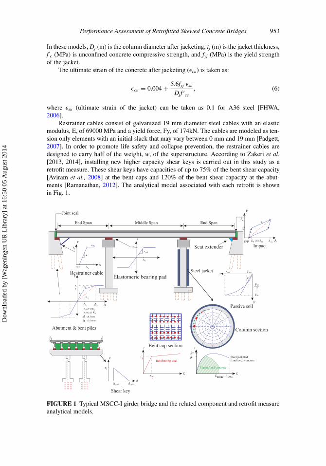
In order to carry out the fragility analyses, three-dimensional nonlinear finite element mod-els are developed in OpenSees [McKenna et al., 2010]. Since the deck is expected to remainelastic during seismic excitations, the composite slab and girders are modeled with lin-ear beam-column centerline elements. The mechanical and geometric properties of thedeck are then assigned to these elements. In order to capture the coupling response inskewed bridges, additional transverse rigid elements are defined and distributed masses areassigned to the nodes on both the longitudinal and transverse deck elements. The effect ofpounding between the deck and the abutment (as a critical phenomenon in skewed bridges)is modeled using elements with a bi-linear force-deformation response following recom-mendations by Muthukumar and DesRoches [2006], normal to the face of the deck. Thehyperbolic soil model recommended by Shamsabadi et al. [2010] is used in this study tocapture the effect of the passive soil response at the abutments. Piles at the abutments orbent foundations are modeled using bi-linear elastic springs, following Nielson [2005]. Theshear keys are located at the abutments and bents in the case of MSCC-IG bridges and aremodeled based on the experimental tests conducted by Megally et al. [2001]. Elastic per-fectly plastic elements, whose behavior is dominated by friction between the rubber andconcrete, are used to model the elastomeric bearings of the girders. Fiber-defined crosssections are used for the columns and bent caps due to the unique advantage of allowingthe assignment of different material properties to different parts of the element cross sec-tion. A bilinear model is defined for the reinforcing steel with a strain hardening of 0.18.Stress-strain models for the confined and unconfined concrete are applied to the concretein the core and cover fibers.
Regarding the retrofit strategies, only an overview of the retrofit measures’ designis presented and additional details are available in Zakeri et al. [2013]. Steel jackets aremodeled by altering the fiber section of the concrete column. The compressive strength andultimate strain of the un-confined concrete of the cover and low confined concrete of thecore are improved due to the extra confinement provided by the jacketing. The compressivestrength of the concrete due to confinement (f ′cc) is estimated following Chai et al. [1991]and is presented in the following equations:
f ′cc = f ′c
(2.254
√1 + 7.94f ′l
f ′c− 2f ′l
f ′c1.254
)(4)
f ′l = 2tjfyj(Dj − tj
) . (5)
Dow
nloa
ded
by [
Wag
enin
gen
UR
Lib
rary
] at
16:
50 0
5 A
ugus
t 201
4
Performance Assessment of Retrofitted Skewed Concrete Bridges 953
In these models, Dj (m) is the column diameter after jacketing, tj (m) is the jacket thickness,f′c (MPa) is unconfined concrete compressive strength, and fyj (MPa) is the yield strengthof the jacket.
The ultimate strain of the concrete after jacketing (εcu) is taken as:
εcu = 0.004 + 5.6fyj εsu
Djf ′cc
, (6)
where εsu (ultimate strain of the jacket) can be taken as 0.1 for A36 steel [FHWA,2006].
Restrainer cables consist of galvanized 19 mm diameter steel cables with an elasticmodulus, E, of 69000 MPa and a yield force, Fy, of 174kN. The cables are modeled as ten-sion only elements with an initial slack that may vary between 0 mm and 19 mm [Padgett,2007]. In order to promote life safety and collapse prevention, the restrainer cables aredesigned to carry half of the weight, w, of the superstructure. According to Zakeri et al.[2013, 2014], installing new higher capacity shear keys is carried out in this study as aretrofit measure. These shear keys have capacities of up to 75% of the bent shear capacity[Aviram et al., 2008] at the bent caps and 120% of the bent shear capacity at the abut-ments [Ramanathan, 2012]. The analytical model associated with each retrofit is shownin Fig. 1.
Restrainer cable
Joint seal
End Span Middle Span
Elastomeric bearing pad
End Span
Seat extender
f f
Reinforcing steelf Steel jacketed
(confined) concrete
Unconfined concrete
Steel jacket
y
y
Bent cap section
F
Fy
Kpad
y
F
Slack
K
0.1K
y
Fy
F
K1
K2
K
F1
F2
K1 =2.33 Keff
K2 =0.43 Keff
eff
2
1=8.3mm
2=25.4mm
Abutment & bent piles
F
yyave
Fult
2
Fult
ymax
K
Passive soil
Pu
gap max
F
Shear key
F
gap
K1
Fy
Fm
y m=0.1
K2
m
Impact
cu,uc cu,c
fc
fcc
Column section
1
FIGURE 1 Typical MSCC-I girder bridge and the related component and retrofit measureanalytical models.
Dow
nloa
ded
by [
Wag
enin
gen
UR
Lib
rary
] at
16:
50 0
5 A
ugus
t 201
4

954 B. Zakeri and G. G. Amiri
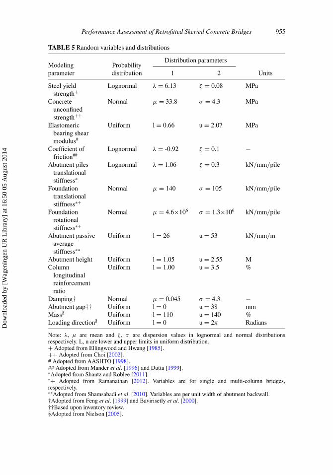
3.2. Bridges and Retrofit Measure Uncertainties
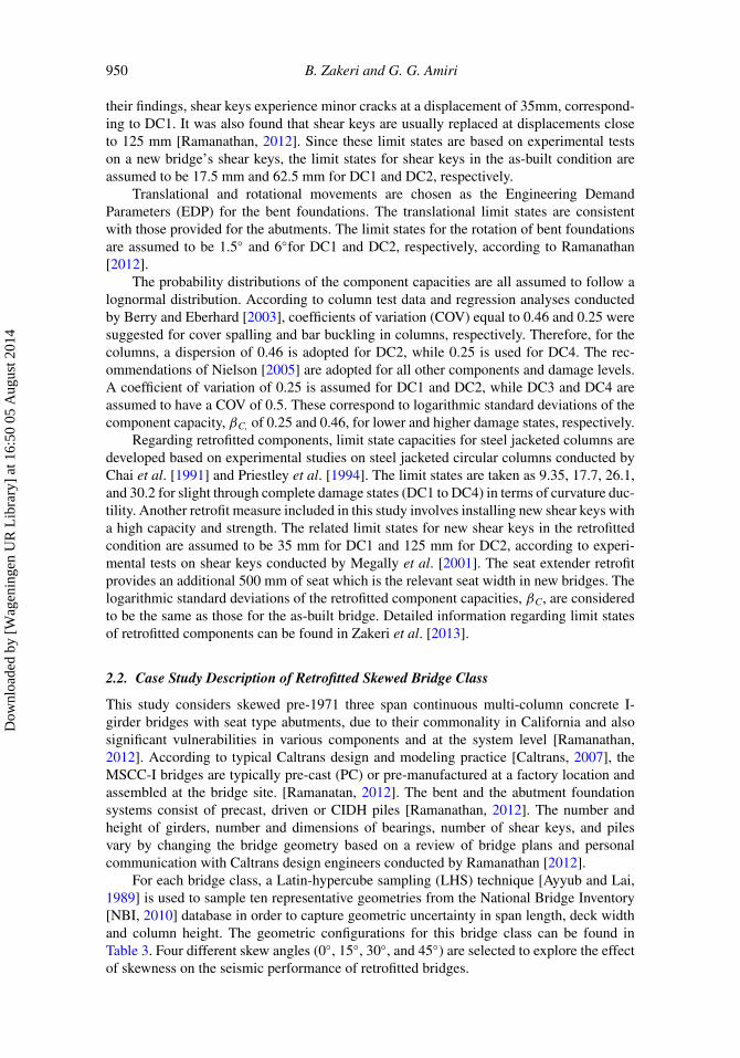
In order to carry out a fragility analysis, a total of 100 statistical bridge samples, of thisclass of as-built and retrofitted bridge, are developed and paired with 100 ground motions.A Quasi-Monte Carlo sampling strategy [Morokoff and Caflisch, 1995] is implementedto account for the uncertainties related to bridge modeling, such as variation in materialand component properties for both the non retrofitted and retrofitted bridges. The proposedretrofit measures themselves have additional material and modeling uncertainties. Commonuncertainties associated with the modeling of as-built and retrofitted bridges are describedin Tables 5 and 6, respectively
3.3. Characteristic of the Ground Motion Suites
The results of 100 nonlinear time history analyses, carried out using four bins of twentytypical non-near fault records identified by Krawinkler et al. [2003] from the PEER StrongMotion Database and one bin of 20 near fault California records from the SAC project database, are used to construct probabilistic seismic demand models. These ground motionshave been used in past probabilistic studies [Mackie and Stojadinovic, 2001; Shafieezadehet al., 2012] and are described in detail in the aforementioned references. The adoption of100 records covering a range of ground motions exceeds the recommended minimum num-ber of records suggested by Nielson and Mackie [2009]. Each set of orthogonal groundmotions is randomly paired with a bridge sample producing a total of 100 nonlineardynamic analyses for each skewed and retrofitted bridge sub-class.
4. Fragility Analysis of Retrofitted Skewed Bridge at the Component andSystem Levels
4.1. Component Level Fragility Curves in Their As-Built and Retrofitted Conditions
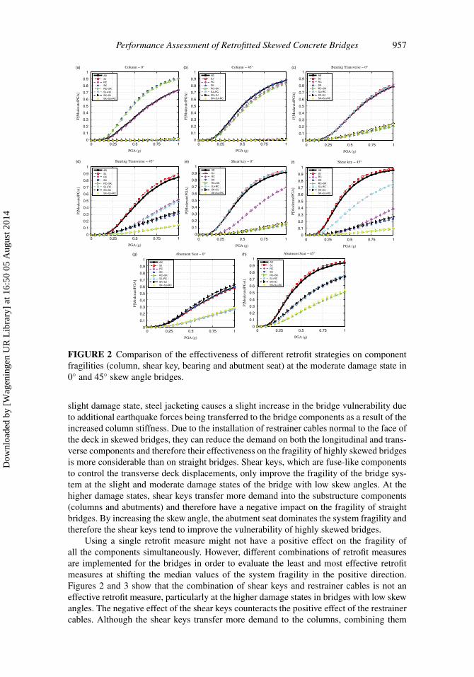
Fragility curves for different components in their as-built and retrofitted conditions aredeveloped to explore the effect of various retrofit measures as well as skewness on theirfragility. The effect of the retrofit measures on the fragility of the columns, shear keys,bearing displacement in the transverse direction and the abutment seat are depicted in Fig. 2for the 0◦ and 45◦ skewed bridges. It can be concluded from the figures that steel jacket-ing is a retrofit measure that only affects column fragility and doesn’t have any positiveeffect on other components. Since using steel jacketing increases the column stiffness,more earthquake force is transferred to the bridge and therefore other components suchas bearings, shear keys, and the abutment seat experience higher demands at the slightand moderate damage states. Shear keys, restrainer cables, and a combination of these tworetrofit measures do not have a positive effect on the vulnerability of the columns. In highlyskewed bridges with a high potential for deck rotation and coupled response, shear keys andrestrainer cables have a considerable effect on the fragility of the bearings and abutment seatby reducing the deck displacement in both the transverse and longitudinal directions. Usingrestrainer cables cannot improve the transverse bearing fragility due to the initial slack ofthe cables. By increasing the skew angle and the relative deck displacement, restrainercables become more effective for bridges with smaller skew angles. While steel jacket-ing does not have a positive effect on the fragility of shear keys, using restrainer cableshas a noticeable effect on decreasing shear keys’ vulnerability, particularly in bridges withlarger skew angles. Since the abutment seat fragility is dependent on the longitudinal dis-placement of the deck, the effect of using restrainer cables and shear keys on the abutment
Dow
nloa
ded
by [
Wag
enin
gen
UR
Lib
rary
] at
16:
50 0
5 A
ugus
t 201
4
Performance Assessment of Retrofitted Skewed Concrete Bridges 955
TABLE 5 Random variables and distributions
Distribution parametersModelingparameter
Probabilitydistribution 1 2 Units
Steel yieldstrength+
Lognormal λ = 6.13 ζ = 0.08 MPa
Concreteunconfinedstrength++
Normal μ = 33.8 σ = 4.3 MPa
Elastomericbearing shearmodulus#
Uniform l = 0.66 u = 2.07 MPa
Coefficient offriction##
Lognormal λ = -0.92 ζ = 0.1 −
Abutment pilestranslationalstiffness∗
Lognormal λ = 1.06 ζ = 0.3 kN/mm/pile
Foundationtranslationalstiffness∗+
Normal μ = 140 σ = 105 kN/mm/pile
Foundationrotationalstiffness∗+
Normal μ = 4.6×10⁶ σ = 1.3×10⁶ kN/mm/pile
Abutment passiveaveragestiffness∗∗
Uniform l = 26 u = 53 kN/mm/m
Abutment height Uniform l = 1.05 u = 2.55 MColumn
longitudinalreinforcementratio
Uniform l = 1.00 u = 3.5 %
Damping† Normal μ = 0.045 σ = 4.3 −Abutment gap†† Uniform l = 0 u = 38 mmMass§ Uniform l = 110 u = 140 %Loading direction§ Uniform l = 0 u = 2π Radians
Note: λ, μ are mean and ζ , σ are dispersion values in lognormal and normal distributionsrespectively. L, u are lower and upper limits in uniform distribution.+ Adopted from Ellingwood and Hwang [1985].++ Adopted from Choi [2002].# Adopted from AASHTO [1998].## Adopted from Mander et al. [1996] and Dutta [1999].∗Adopted from Shantz and Roblee [2011].∗+ Adopted from Ramanathan [2012]. Variables are for single and multi-column bridges,respectively.∗∗Adopted from Shamsabadi et al. [2010]. Variables are per unit width of abutment backwall.†Adopted from Feng et al. [1999] and Bavirisetly et al. [2000].††Based upon inventory review.§Adopted from Nielson [2005].
Dow
nloa
ded
by [
Wag
enin
gen
UR
Lib
rary
] at
16:
50 0
5 A
ugus
t 201
4
956 B. Zakeri and G. G. Amiri
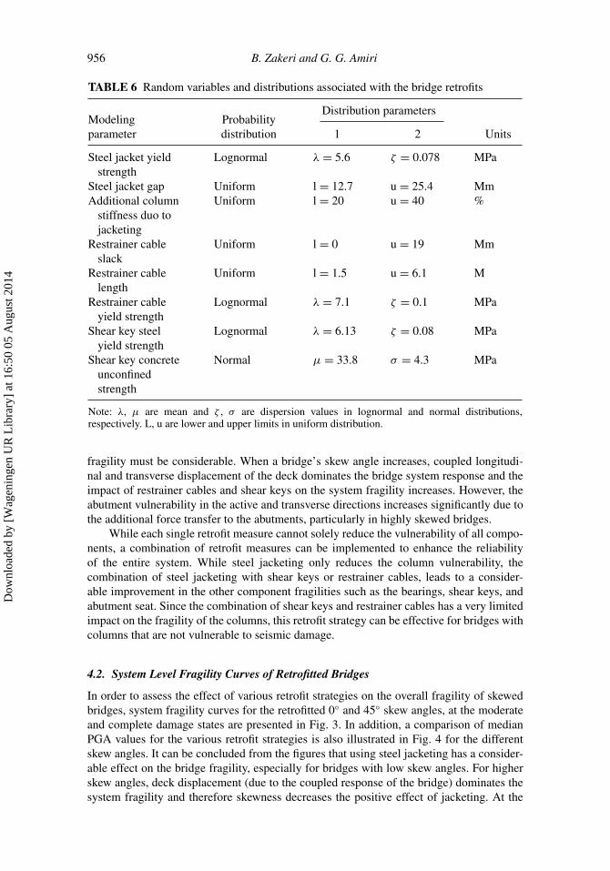
TABLE 6 Random variables and distributions associated with the bridge retrofits
Distribution parametersModelingparameter
Probabilitydistribution 1 2 Units
Steel jacket yieldstrength
Lognormal λ = 5.6 ζ = 0.078 MPa
Steel jacket gap Uniform l = 12.7 u = 25.4 MmAdditional column
stiffness duo tojacketing
Uniform l = 20 u = 40 %
Restrainer cableslack
Uniform l = 0 u = 19 Mm
Restrainer cablelength
Uniform l = 1.5 u = 6.1 M
Restrainer cableyield strength
Lognormal λ = 7.1 ζ = 0.1 MPa
Shear key steelyield strength
Lognormal λ = 6.13 ζ = 0.08 MPa
Shear key concreteunconfinedstrength
Normal μ = 33.8 σ = 4.3 MPa
Note: λ, μ are mean and ζ , σ are dispersion values in lognormal and normal distributions,respectively. L, u are lower and upper limits in uniform distribution.
fragility must be considerable. When a bridge’s skew angle increases, coupled longitudi-nal and transverse displacement of the deck dominates the bridge system response and theimpact of restrainer cables and shear keys on the system fragility increases. However, theabutment vulnerability in the active and transverse directions increases significantly due tothe additional force transfer to the abutments, particularly in highly skewed bridges.
While each single retrofit measure cannot solely reduce the vulnerability of all compo-nents, a combination of retrofit measures can be implemented to enhance the reliabilityof the entire system. While steel jacketing only reduces the column vulnerability, thecombination of steel jacketing with shear keys or restrainer cables, leads to a consider-able improvement in the other component fragilities such as the bearings, shear keys, andabutment seat. Since the combination of shear keys and restrainer cables has a very limitedimpact on the fragility of the columns, this retrofit strategy can be effective for bridges withcolumns that are not vulnerable to seismic damage.
4.2. System Level Fragility Curves of Retrofitted Bridges
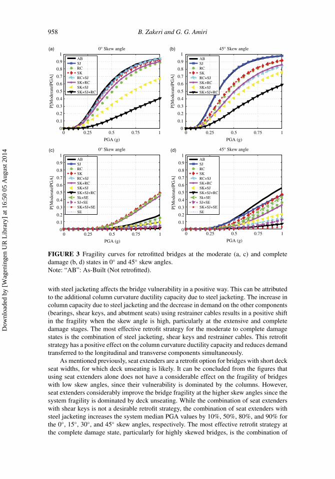
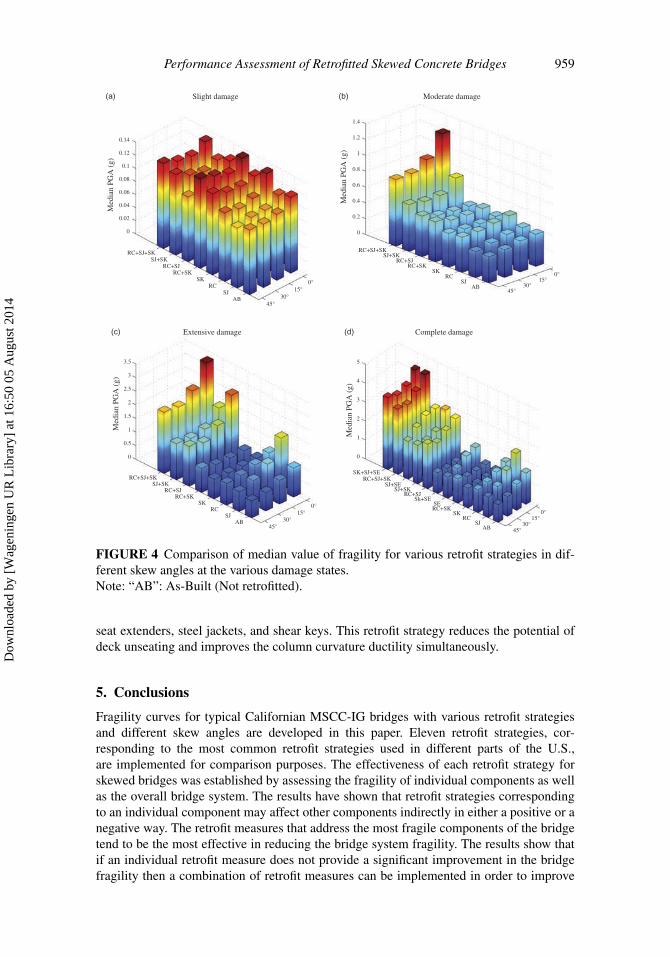
In order to assess the effect of various retrofit strategies on the overall fragility of skewedbridges, system fragility curves for the retrofitted 0◦ and 45◦ skew angles, at the moderateand complete damage states are presented in Fig. 3. In addition, a comparison of medianPGA values for the various retrofit strategies is also illustrated in Fig. 4 for the differentskew angles. It can be concluded from the figures that using steel jacketing has a consider-able effect on the bridge fragility, especially for bridges with low skew angles. For higherskew angles, deck displacement (due to the coupled response of the bridge) dominates thesystem fragility and therefore skewness decreases the positive effect of jacketing. At the
Dow
nloa
ded
by [
Wag
enin
gen
UR
Lib
rary
] at
16:
50 0
5 A
ugus
t 201
4
Performance Assessment of Retrofitted Skewed Concrete Bridges 957
0 0.25 0.5 0.75 10
0.1
0.2
0.3
0.4
0.5
0.6
0.7
0.8
0.9
1
PGA (g)
0 0.25 0.5 0.75 1
PGA (g)
0 0.25 0.5 0.75 1
PGA (g)
0 0.25 0.5 0.75 1
PGA (g)
0 0.25 0.5 0.75 1
PGA (g)
0 0.25 0.5 0.75 1
PGA (g)
0 0.25 0.5 0.75 1
PGA (g)
0 0.25 0.5 0.75 1
PGA (g)
P[M
oder
ate|
PGA
]
0
0.1
0.2
0.3
0.4
0.5
0.6
0.7
0.8
(a)
(d) (e) (f)
(g) (h)
(b) (c)
0.9
1P[
Mod
erat
e|PG
A]
0
0.1
0.2
0.3
0.4
0.5
0.6
0.7
0.8
0.9
1
P[M
oder
ate|
PGA
]
0
0.1
0.2
0.3
0.4
0.5
0.6
0.7
0.8
0.9
1
P[M
oder
ate|
PGA
]
0
0.1
0.2
0.3
0.4
0.5
0.6
0.7
0.8
0.9
1
P[M
oder
ate|
PGA
]
0
0.1
0.2
0.3
0.4
0.5
0.6
0.7
0.8
0.9
1
P[M
oder
ate|
PGA
]
0
0.1
0.2
0.3
0.4
0.5
0.6
0.7
0.8
0.9
1
P[M
oder
ate|
PGA
]
0
0.1
0.2
0.3
0.4
0.5
0.6
0.7
0.8
0.9
1
P[M
oder
ate|
PGA
]
Column − 0°
ABSJRCSKRC+SKSJ+RCSK+SJSK+SJ+RC
Column − 45° Bearing Transverse − 0°
Bearing Transverse − 45° Shear key − 0° Shear key − 45°
Abutment Seat − 0° Abutment Seat − 45°
ABSJRCSKRC+SKSJ+RCSK+SJSK+SJ+RC
ABSJRCSKRC+SKSJ+RCSK+SJSK+SJ+RC
ABSJRCSKRC+SKSJ+RCSK+SJSK+SJ+RC
ABSJRCSKRC+SKSJ+RCSK+SJSK+SJ+RC
ABSJRCSKRC+SKSJ+RCSK+SJSK+SJ+RC
ABSJRCSKRC+SKSJ+RCSK+SJSK+SJ+RC
ABSJRCSKRC+SKSJ+RCSK+SJSK+SJ+RC
FIGURE 2 Comparison of the effectiveness of different retrofit strategies on componentfragilities (column, shear key, bearing and abutment seat) at the moderate damage state in0◦ and 45◦ skew angle bridges.
slight damage state, steel jacketing causes a slight increase in the bridge vulnerability dueto additional earthquake forces being transferred to the bridge components as a result of theincreased column stiffness. Due to the installation of restrainer cables normal to the face ofthe deck in skewed bridges, they can reduce the demand on both the longitudinal and trans-verse components and therefore their effectiveness on the fragility of highly skewed bridgesis more considerable than on straight bridges. Shear keys, which are fuse-like componentsto control the transverse deck displacements, only improve the fragility of the bridge sys-tem at the slight and moderate damage states of the bridge with low skew angles. At thehigher damage states, shear keys transfer more demand into the substructure components(columns and abutments) and therefore have a negative impact on the fragility of straightbridges. By increasing the skew angle, the abutment seat dominates the system fragility andtherefore the shear keys tend to improve the vulnerability of highly skewed bridges.
Using a single retrofit measure might not have a positive effect on the fragility ofall the components simultaneously. However, different combinations of retrofit measuresare implemented for the bridges in order to evaluate the least and most effective retrofitmeasures at shifting the median values of the system fragility in the positive direction.Figures 2 and 3 show that the combination of shear keys and restrainer cables is not aneffective retrofit measure, particularly at the higher damage states in bridges with low skewangles. The negative effect of the shear keys counteracts the positive effect of the restrainercables. Although the shear keys transfer more demand to the columns, combining them
Dow
nloa
ded
by [
Wag
enin
gen
UR
Lib
rary
] at
16:
50 0
5 A
ugus
t 201
4
958 B. Zakeri and G. G. Amiri
0 0.25 0.5 0.75 10
0.1
0.2
0.3
0.4
0.5
0.6
0.7
0.8
0.9
1(a)
PGA (g)
0 0.25 0.5 0.75 1
PGA (g)
P[M
oder
ate|
PGA
]
0
0.1
0.2
0.3
0.4
0.5
0.6
0.7
0.8
0.9
1(c)
P[M
oder
ate|
PGA
]
0
0.1
0.2
0.3
0.4
0.5
0.6
0.7
0.8
0.9
1(d)
P[M
oder
ate|
PGA
]
0
0.1
0.2
0.3
0.4
0.5
0.6
0.7
0.8
0.9
1(b)
P[M
oder
ate|
PGA
]
0° Skew angle
ABSJRCSKRC+SJSK+RCSK+SJSK+SJ+RC
45° Skew angle
ABSJRCSKRC+SJSK+RCSK+SJSK+SJ+RC
0° Skew angle
ABSJRCSKRC+SJSK+RCSK+SJSK+SJ+RCSk+SESJ+SESK+SJ+SESE
45° Skew angle
ABSJRCSKRC+SJSK+RCSK+SJSK+SJ+RCSk+SESJ+SESK+SJ+SESE
0 0.25 0.5 0.75 1
PGA (g)
0 0.25 0.5 0.75 1
PGA (g)
FIGURE 3 Fragility curves for retrofitted bridges at the moderate (a, c) and completedamage (b, d) states in 0◦ and 45◦ skew angles.Note: “AB”: As-Built (Not retrofitted).
with steel jacketing affects the bridge vulnerability in a positive way. This can be attributedto the additional column curvature ductility capacity due to steel jacketing. The increase incolumn capacity due to steel jacketing and the decrease in demand on the other components(bearings, shear keys, and abutment seats) using restrainer cables results in a positive shiftin the fragility when the skew angle is high, particularly at the extensive and completedamage stages. The most effective retrofit strategy for the moderate to complete damagestates is the combination of steel jacketing, shear keys and restrainer cables. This retrofitstrategy has a positive effect on the column curvature ductility capacity and reduces demandtransferred to the longitudinal and transverse components simultaneously.
As mentioned previously, seat extenders are a retrofit option for bridges with short deckseat widths, for which deck unseating is likely. It can be concluded from the figures thatusing seat extenders alone does not have a considerable effect on the fragility of bridgeswith low skew angles, since their vulnerability is dominated by the columns. However,seat extenders considerably improve the bridge fragility at the higher skew angles since thesystem fragility is dominated by deck unseating. While the combination of seat extenderswith shear keys is not a desirable retrofit strategy, the combination of seat extenders withsteel jacketing increases the system median PGA values by 10%, 50%, 80%, and 90% forthe 0◦, 15◦, 30◦, and 45◦ skew angles, respectively. The most effective retrofit strategy atthe complete damage state, particularly for highly skewed bridges, is the combination of
Dow
nloa
ded
by [
Wag
enin
gen
UR
Lib
rary
] at
16:
50 0
5 A
ugus
t 201
4
Performance Assessment of Retrofitted Skewed Concrete Bridges 959
0°15°
30°45°
ABSJ
RCSK
RC+SKRC+SJ
SJ+SKRC+SJ+SK
0
0.02
0.04
0.06
0.08
0.1
0.12
0.14
Slight damage(a)
(c) (d)
(b)
Med
ian
PGA
(g)
0°15°
30°45°
ABSJ
RCSK
RC+SKRC+SJ
SJ+SKRC+SJ+SK
0
0.2
0.4
0.6
0.8
1
1.2
1.4
Moderate damage
Med
ian
PGA
(g)
0°15°
30°45°
ABSJ
RCSK
RC+SKRC+SJ
SJ+SKRC+SJ+SK
0
0.5
1
1.5
2
2.5
3
3.5
Extensive damage
Med
ian
PGA
(g)
0°15°
30°45°AB
SJRC
SKRC+SKSE
Sk+SERC+SJ
SJ+SKSJ+SE
RC+SJ+SKSK+SJ+SE
0
1
2
3
4
5
Complete damage
Med
ian
PGA
(g)
FIGURE 4 Comparison of median value of fragility for various retrofit strategies in dif-ferent skew angles at the various damage states.Note: “AB”: As-Built (Not retrofitted).
seat extenders, steel jackets, and shear keys. This retrofit strategy reduces the potential ofdeck unseating and improves the column curvature ductility simultaneously.
5. Conclusions
Fragility curves for typical Californian MSCC-IG bridges with various retrofit strategiesand different skew angles are developed in this paper. Eleven retrofit strategies, cor-responding to the most common retrofit strategies used in different parts of the U.S.,are implemented for comparison purposes. The effectiveness of each retrofit strategy forskewed bridges was established by assessing the fragility of individual components as wellas the overall bridge system. The results have shown that retrofit strategies correspondingto an individual component may affect other components indirectly in either a positive or anegative way. The retrofit measures that address the most fragile components of the bridgetend to be the most effective in reducing the bridge system fragility. The results show thatif an individual retrofit measure does not provide a significant improvement in the bridgefragility then a combination of retrofit measures can be implemented in order to improve
Dow
nloa
ded
by [
Wag
enin
gen
UR
Lib
rary
] at
16:
50 0
5 A
ugus
t 201
4
960 B. Zakeri and G. G. Amiri
bridge performance significantly. A comparison between the bridge fragilities with differ-ent skew angles has clarified that the most effective retrofit strategy might not be the samefor a straight and a highly skewed bridge.
It is found that among the single component retrofit strategies, shear keys do not havepositive effect on the fragility of bridges with low skew angles at the extensive and com-plete damage states, due to the increased transfer of inertial loads to vulnerable components,when the bridge is excited in the transverse direction. Since steel jacketing only improvesthe fragility of columns, it has a positive effect on the fragility of bridges with low skewangles, as the bridge vulnerability is dominated by the columns. Restrainer cables decreasedeck displacement and demand on the bearings, columns, and shear keys, and therefore,have a noticeable effect on the fragility of the bridge. Restrainer cables have a greater effecton the fragility of highly skewed bridges due to their contribution to decreasing the demandon both the longitudinal and transverse components. If an individual retrofit measure cannotsatisfy the minimum performance levels of the bridge, a combination of retrofit measurescan also be adopted. The results show that the combination of retrofit measures does notalways have a positive effect on the bridge vulnerability. Since columns are one of the mostimportant components due to the fact that they dominate the bridge fragility, the combina-tion of shear keys and restrainer cables cannot have a considerable effect on the fragilityof bridges with low skew angles. However, steel jacketing combined with shear keys orrestrainer cables results in a remarkable effect of shifting the median values of PGA (reduc-ing the bridge fragility). The combination of steel jacketing, restrainer cables and shear keysis the most effective retrofit strategy at the slight to extensive damage states. The combina-tion of seat extenders, steel jacketing, and shear keys is the most effective retrofit strategyfor this class of bridge at the complete damage state, due to its ability to reduce the potentialof deck unseating, to resist the transverse displacements induced by inertial forces in thetransverse direction and to increase the column capacity. The effectiveness of the retrofitmeasure at improving the system fragility depends on the damage state and skew anglebeing considered. The proposed fragility curves provide a good opportunity for decisionmakers to select suitable retrofit strategies for skewed MSCC-IG girder bridges and serveas key elements for risk or cost-benefit analyses. Additional future research opportunitiesinclude the need to consider the effect of the number of spans, different retrofit measuresand vertical ground motions on the fragility of this class or other classes of bridges.
References
AASHTO [1998] LRFD Bridge Design Specifications. American Association of State Highway andTransportation Officials, Washington, D.C.
Agrawal, A. K., Ghosn, M., Alampalli, S., and Pan, Y [2011] “Seismic fragility of retrofittedmulti-span continuous steel bridges in New York,” Journal of Bridge Engineering, ASCE.DOI:10.1061/(ASCE)BE.1943-5592.0000290.
Aviram, A., Mackie, K. R., and Stojadinovic, B. [2008] “Guidelines for nonlinear analysis ofbridge structures in California,” PEER Report 2008/03. Pacific Earthquake Engineering ResearchCenter, University of California, Berkeley.
Ayyub, B. M. and Lai, K. L [1989] “Structural reliability assessment using Latin hypercubesampling,” Proc. of ICOSSAR’89, The 5th International Conference on Structural Safety andReliability, Part II. ASCE, San Francisco, California.
Bavirisetty, R., Vinayagamoorthy, M., and Duan, L. [2000] “Dynamic analysis,” in BridgeEngineering Handbook, eds. W.-F. Chen and L. Duan (CRC Press, Boca Raton, Florida).
Berry, M. P. and Eberhard, M. O. [2003] “Performance Models for flexural damage in reinforcedconcrete columns,” PEER Report 2003/18. Pacific Earthquake Engineering Research Center,University of Washington, Seattle, Washington.
Dow
nloa
ded
by [
Wag
enin
gen
UR
Lib
rary
] at
16:
50 0
5 A
ugus
t 201
4

Performance Assessment of Retrofitted Skewed Concrete Bridges 961
Caltrans [2007] “Reinforced concrete bridge capacity assessment training manual,” Report sub-mitted to Structure Maintenance and Investigations, California Department of Transportation,Sacramento, California.
Chai, Y. H., Priestley, M. J. N., and Seible, F. [1991] “Flexural retrofit of circular reinforced concretebridge columns by steel jackets,” Report number SSRP-91/06, Department of Applied Mechanicsand Engineering Sciences, University of California, San Diego.
Choi, E. [2002] “Seismic analysis and retrofit of Mid-America bridges,” Ph.D. thesis, GeorgiaInstitute of Technology, Atlanta, Georgia.
Choi, E., DesRoches, R., and Nielson, B. [2004] “Seismic fragility of typical bridges in moderateseismic zones,” Journal of Engineering Structures 26, 187–199.
Cornell, C. A., Jalayer, F., Hamburger, R. O., and Foutch, D. A. [2002] “Probabilistic basis for2000 SAC Federal Emergency Management Agency steel moment frame guidelines,” Journalof Structural Engineering 128(4), 526–533.
DesRoches, R., Pfeifer, T., Leonand, R. T., and Lam, T. [2003] “Full-scale tests of seismic cablerestrainer retrofits for simply supported bridges,” Journal of Bridge Engineering 8, 191–198.
Dimitrakopoulos, E. G. [2011] “Seismic response analysis of skew bridges with pounding deck–abutment joints,” Engineering Structures 33(3), 813–826.
Dutta, A. [1999] “On energy based seismic analysis and design of highway bridges,” Ph.D. thesis,State University of New York at Buffalo, Buffalo, New York.
Ellingwood, B. and Hwang, H. [1985] “Probabilistic descriptions of resistance of safety relatedstructures in nuclear plants,” Nuclear Engineering and Design 88(2), 169–178.
Fang, J., Li, Q., Jeary, A., and Liu, D. [1999] “Damping of tall buildings: Its evaluation andprobabilistic characteristics,” Structural Design of Tall Buildings 8(2), 145–153.
Federal Emergency Management Agency (FEMA) [2005] “HAZUS-MH software,” Washington D.C.FHWA [2006] “Seismic retrofitting manual for highway structures: Part 1 – Bridges,” Report No.
FHWA-RD (MCEER-06-xxxx), Federal Highway Administration, Washington D.C.Galambos, T. V. and Ravindra, M. K. [1978] “Properties of Steel for Use in LRFD,” Journal of
Structural Division 104(9), 1459–1468.Hess, P., Bruchman, D., Assakkaf, I., and Ayyub, M. [2002] “Uncertainties in material strength,
geometric, and load variables,” Naval Engineerings Journal 114(2), 167–180.Hwang, H., Liu, J. B., and Chiu, Y.-H. [2000] “Seismic fragility analysis of highway bridges,” MAEC
RR-4, Center for Earthquake Research Information, Memphis, Tennessee.Kalantari, A. and Amjadian, M. [2010] “An approximate method for dynamic analysis of skewed
highway bridges with continuous rigid deck,” Engineering Structures 32(9), 2850–2860.Kawashima, K. and Shoji, G. [2000] “Effect of restrainers to mitigate pounding between adjacent
decks subjected to a strong ground motion,” 12th World Conference on Earthquake Engineering,Auckland, New Zealand.
Krawinkler, H., Medina, R., and Alavi, B. [2003] “Seismic drift and ductility demands and theirdependence on ground motions,” Journal of Engineering Structures, 25(5), 637–653.
Kwon, O. S. and Jeong, S. H. [2013] “Seismic displacement demands on skewed bridge deckssupported on elastomeric bearings,” Journal of Earthquake Engineering 17, 998–1022.
Liu, K. Y., Chang, K. C., Lu, C. H., and Cheng, W. C. [2008] “Seismic performance of skew bridgewith friction type rubber bearings,” 14th World Conference on Earthquake Engineering, Beijing,China.
Mackie, K. R. and Stojadinovic, B. [2001] “Probabilistic seismic demand model for Californiabridges,” Journal of Bridge Engineering 6, 468–480.
Mackie, K. R. and Stojadinovic, B. [2004] “Fragility curves for reinforced concrete highway overpassbridges,” 13th World Conference on Earthquake Engineering, Vancouver, BC, Canada.
Mander, J. B., Kim, D. K., Chen, S. S., and Premus, G. J. [1996] “Response of steel bridge bearingsto the reversed cyclic loading,” Report No. NCEER 96-0014, NCEER.
Maragakis, E. A. and Jennings, P. C. [1987] “Analytical models for the rigid body motions of skewbridges,” Earthquake Engineering & Structural Dynamics 15(8), 923–944.
McKenna, F., Scott, M., and Fenves, G. L. [2010] “Nonlinear finite-element analysis softwarearchitecture using object composition,” Journal of Computing in Civil Engineering 24(1), 95–107.
Dow
nloa
ded
by [
Wag
enin
gen
UR
Lib
rary
] at
16:
50 0
5 A
ugus
t 201
4

962 B. Zakeri and G. G. Amiri
Megally, S. H., Silva, P. F., and Seible, F. [2001] “Seismic response of sacrificial shearkeys inbridge abutments,” Report No. SSRP-200l/23, Department of Structural Engineering, Universityof California, San Diego.
Meng, J. Y., Lui, E. M., and Liu, Y. [2001] “Dynamic response of skew highway bridges,” Journal ofEarthquake Engineering 5(2), 205–223.
Morokoff, W. J. and Caflisch, R. E. [1995] “Quasi-Monte Carlo integration,” Journal ofComputational Physics 122, 218–230.
Muthukumar, S. and DesRoches, R. A. [2006] “Hertz contact model with non-linear damping forpounding simulation,” Journal of Earthquake Engineering and Structural Dynamics 35, 811–828.
NBI [2010] “National bridge inventory data,” U.S. Department of Transportation, Federal HighwayAdministration, Washington, D.C.; http://www.fhwa.dot.gov/bridge/nbi/ascii.cfm.
Nielson, B. G. [2005] “Analytical fragility curves for highway bridges in moderate seismic zones,”Ph.D. dissertation, Georgia Institute of Technology, Atlanta, Georgia.
Nielson, B. G. and DesRoches, R. [2007] “Analytical seismic fragility curves for typical bridges inthe central and southeastern United States,” Earthquake Spectra 23, 615–633.
Nielson, B. G. and Mackie, K. R. [2009] “Tracking uncertainties from component level to systemlevel fragility analyses through simulation,” Proc. of the 2009 TCLEE Conference, Oakland,California.
Padgett, J. E. [2007] “Seismic vulnerability assessment of retrofitted bridges using probabilisticmethods,” Ph.D. dissertation, Georgia Institute of Technology, Atlanta, Georgia.
Padgett, J. E. and DesRoches, R. [2008] “Methodology for development of analytical fragility curvesfor retrofitted bridges,” Earthquake Engineering and Structural Dynamics 37(8), 157–1174.
Padgett, J. E., Nielson, B. G., and DesRoches, R. [2008] “Selection of optimal intensity measures inprobabilistic seismic demand models of highway bridge portfolios,” Earthquake Engineering andStructural Dynamics 37(5), 711–725.
Padgett, J. E. and DesRoches, R. [2009] “Retrofitted bridge fragility analysis for typical classes ofmultispan bridges,” Journal of Earthquake Spectra 25(1), 117–141.
Priestley, M. J. N. and Seible, F. [1991] “Seismic assessment and retrofit of bridges,” Research ReportSSRP-91/03, Dept. of Applied Mechanics and Engineering Sciences, University of California,San Diego.
Priestley, M. J. N., Seisble, F., and Chai, Y. H. [1992], “Seismic retrofit of bridge columns using steeljackets,” Earthquake Engineering, Tenth Word Conference, Balkema, Rotterdam.
Priestley, M. J. N., Seisble, F., Xiao, Y., and Verma, R. [1994] “Steel jacket retrofitting of reinforcedconcrete bridge columns for enhanced shear strength-part 1: theoretical considerations and testdesign,” ACI Structural Journal 91(4), 394–405.
Ramanathan, N. K. [2012] “Next generation seismic fragility curves for California bridges incorpo-rating the evolution in seismic design philosophy,” Ph.D. thesis, Georgia Institute of Technology,Atlanta, Georgia.
Roberts, J. E. [1998] “Seismic design philosophy for California bridges,” Proc. of the StructuralEngineers World Congress, San Francisco, California.
Robinson, R. R., Longinow, A., and Chu, K. H. [1979] Seismic Retrofit Measures for HighwayBridges, Volumes I and II. Federal Highway Administration, Department of Transportation,Washington, D.C.
SAC Los Angeles project database; http://nisee.berkeley.edu/data/strong_motion/sacsteel/ground_motions.html.
Saiidi, M., Maragakis, E., and Feng, S. [1996] “Parameters in bridge restrainer design for seismicretrofit,” Journal of Structural Engineering 122, 61–68.
Saiidi, M., Randall, M., Maragakis, E. A., and Isakovic, T. [2001] “Seismic restrainer design methodsfor simply supported bridges,” Journal of Bridge Engineering 6(5), 307–315.
Schroeder, B. L. [2006] “Seismic response assessment of skew highway bridges,” M.S. thesis,University of Nevada, Reno, Nevada.
Sevgili, G. and Caner, A. [2009] “Improved seismic response of multi simple-span skewed bridgesretrofitted with link slabs,” Journal of Bridge Engineering 14(6), 452–459.
Dow
nloa
ded
by [
Wag
enin
gen
UR
Lib
rary
] at
16:
50 0
5 A
ugus
t 201
4

Performance Assessment of Retrofitted Skewed Concrete Bridges 963
Shafieezadeh, A., Ramanathan, K., Padgett, J. E., and DesRoches, R. [2012] “Fractional order inten-sity measures for probabilistic seismic demand modeling applied to highway bridges,” EarthquakeEngineering & Structural Dynamics 41(3), 391–409.
Sahs, S., Veletzos, M., Panagiutou, M., and Restrepo, J. [2008] “Visual inspection and capacityassessment of earthquake damaged reinforced concrete bridge elements,” Integrate Research andDeployment Final Report, California Department of Transportation, Sacramento, California.
Shamsabadi, A., Kapuskar, M. and Martin, G. R. [2006] “Nonlinear seismic soil-abutment-structureinteraction analysis of skewed bridges,” Fifth National Seismic Conference on Bridges andHighways: Innovation in Earthquake Engineering for Highway Structures, San Francisco,California.
Shamsabadi, A., Khalili-Tehrani, P., Stewart, J. P., and Taciroglu, E. [2010] “Validated simula-tion models for lateral response of bridge abutments with typical backfills,” Journal of BridgeEngineering, ASCE 15(3), 302–311.
Shantz, T. and Roblee, C. [2011] “Estimates of foundation springs, piles capacities and uncertaintiesfor typical Caltrans bridges,” [email] (Personal communication with Ramanathan, K., DesRoches,R., Padgett, J., Dukes, J., and Turner, L.).
Shinozuka, M. [1998] “Statistical Analysis of bridge fragility curves,” Proc. of the US-Italy Workshopon Protective Systems for Bridges, New York.
Watanabe, G. and Kawashima, K. [2004] “Effectiveness of cable-restrainers for mitigating rotationof a skewed bridge subjected to strong ground shaking,” 13th World Conference on EarthquakeEngineering, Vancouver, B.C., Canada,.
Wright, T., DesRoches, R., and Padgett, J. E. [2011] “Bridge seismic retrofitting practices in thecentral and southeastern United States,” Journal of Bridge Engineering 16(1), 82–92.
Yang, C. S, DesRoches, R., and Padgett, J. E. [2009] “Analytical fragility models for box girderbridges with and without protective systems,” Proc. of the 2009 Structures Congress, Austin,Texas.
Zakeri, B., Padgett, J. E., and Ghodrati Amiri, G. [2013] “Fragility assessment for seismicallyretrofitted skewed reinforced concrete box girder bridges,” Journal of Performance of ConstructedFacilities CDOI:10.1061/(ASCE)CF.1943-5509.0000502.
Zakeri, B., Padgett, J. E., and Ghodrati Amiri, G. [2014] “Fragility analysis of skewed single frameconcrete box girder bridges,” Journal of Performance of Constructed Facilities 28(3), 571–582.
Zhang, J. and Huo, Y. [2008] “Optimum isolation design for highway bridges using fragility functionmethod,” 14th World Conference on Earthquake Engineering, Beijing, China.
Dow
nloa
ded
by [
Wag
enin
gen
UR
Lib
rary
] at
16:
50 0
5 A
ugus
t 201
4