Embed Size (px)
DESCRIPTION
for bridges
Citation preview

7/18/2019 Analysis of Straight and Skewed Box Girder Bridge by Finite Strip Method
http://slidepdf.com/reader/full/analysis-of-straight-and-skewed-box-girder-bridge-by-finite-strip-method 1/8
International Journal of Emerging Technology and Advanced Engineering
Website: www.ijetae.com (ISSN 2250-2459, Volume 2, Issue 11, November 2012)
191
Analysis of Straight and Skewed box Girder Bridge by FiniteStrip Method
Prof. Dr. S.A.Halkude1, Prof. Akim C.Y.2
Principal, Walchand Institute of Technology, Sholapur
Asst. Professor in Civil Engg.Dept., Deogiri Institute of Engineering and Management Studies, Aurangabad
Abstract — Generally a box girder is a beam and hence
bending and shear actions exist in longitudinal direction. Due
to the thin walled and widespread cross-section, the shear is
not uniform even along the width of horizontal plates. When
subjected to eccentric loading, the section exhibits torsion. An
exact close form solution for such a continuum with a complex
behavior is almost impossible. Some approximate analytical
methods with simplifying assumptions for loading and
geometry have been used for analysis. The objective of the
research reported in this paper is to obtain analysis of box
Girder Bridge by Finite Strip Method considering various
values of skew angles considering their effect on each nodal
line at specific distance interval along the span of girder by
considering self weight and point load.
Keywords — Finite Strip Method, Box Girder, Skew angle,
Nodal lines, Strips, Load Vector, Stiffness matrix, Strain
energy, Finite Element Method.
I.
I NTRODUCTION
For a structure with constant cross-section and end
boundary conditions that do not change transversely, stress
analysis can be performed using finite strip instead of finite
elements. In each strip, the displacement component at any
point is expressed in terms of the displacement parameters
of nodal lines by means of simple polynomials in the
transverse direction and continuously differentiable smooth
series in the longitudinal direction. With the stipulation that
such series should satisfy the boundary conditions at the
ends of the strip. Using Strain-displacement relationships,
the strain energy of the structure and the potential energy of
external loads can be expressed in terms of the
displacement parameters should make the total potential
energy of the structure become minimum. This yields a set
of linear algebraic equations with the displacement parameters, the displacement and stress components at any
point in the structure can be obtained.
II.
FINITE STRIP MODELING OF BRIDGES
Selection of the best approach and the most suitable type
of strip is based mainly on the bridge geometry, namely the
shape and support conditions. The load conditions should
also be considered. For a right or skew slab of box Girder
Bridge with a constant cross-section and simply supported
ends, the finite strip method is the most efficient method. It
reduces to half bandwidth of the stiffness matrix
significantly. Therefore the time consumption in forming
this matrix is reduced
Generating a finite strip model
Depending upon the objective of analysis and the
loading conditions, the suitable finite strip model can be
chosen. In using the finite strip method for the overall
analysis of a single span skew box girder bridge, the
following modeling will provide adequate accuracy.
The flanges and webs are idealized as the orthotropic
plates with equivalent elastic properties.
Each web and flange is divided into minimum three
strips. If only the deflection and longitudinal stress are
required, few strips are sufficient. If more accurate
results are desired more strips should be used
considering load act on a nodal line.
In regions with a higher stress gradient, narrower strips
should be used. The width of strip should change
gradually from one strip to another.
If the cross section and loads are both symmetrical about
the centerline, only half of the bridge needs to be
analyzed.
If the bridge is subjected to uniform load only, five to
ten symmetrical harmonies are adequate for the analysis
Numbering nodal lines and strips
In order to minimize the half bandwidth of a stiffness
matrix in a finite strip model, the nodal lines should be
numbered so as to keep the difference between the numbers
of all the nodal lines within each strip at a minimum.

7/18/2019 Analysis of Straight and Skewed Box Girder Bridge by Finite Strip Method
http://slidepdf.com/reader/full/analysis-of-straight-and-skewed-box-girder-bridge-by-finite-strip-method 2/8
International Journal of Emerging Technology and Advanced Engineering
Website: www.ijetae.com (ISSN 2250-2459, Volume 2, Issue 11, November 2012)
192
Modelling of box girder
The numbering of nodal lines and strips for the proposed
box girder model is done as shown below. The Fig.2.2
shows the Finite Strip Model of box girder whereas the
Fig.2.3 shows the Finite Element Model of box girder.
III.
THEORETICAL FORMULATION
Consider a simply supported beam carrying a central
point load at centre and having span L.
The boundary conditions at both ends y = 0 and y = l
are,
w(y) = 0
M(y) = - EI
= 0 3.1
The deflection of the beam by a half – sine wave is,
w(y) = δ sin
3.2
In order to obtain the best approximation the total
potential energy developed in the system become a
minimum.
П = U + W
П =
∫
3.3
The first derivative of П with respect to δ must be zero
П
δ = 0 3.4
П =
δ
∫
δ 3.5
П =
δ
δ 3.6
Then the value of is obtained by solving eq. 3.4
3.7
The deflection function proposed in Equation 1.2
becomes
w(y) = sin 3.8
From which the bending moment is obtained as
M(y) =
2
2
d w EI
dy = sin 3.9
To improve the accuracy using a series of sine function
w(y) =
1
sinr
m
m ym
l
3.10
Applying the energy approach again yields.
w(y) =4
1
1r
m m sin sin
M(y) =2
1
1r
m m sin sin 3.11
This will give resulting deflection and moment at mid
span

7/18/2019 Analysis of Straight and Skewed Box Girder Bridge by Finite Strip Method
http://slidepdf.com/reader/full/analysis-of-straight-and-skewed-box-girder-bridge-by-finite-strip-method 3/8
International Journal of Emerging Technology and Advanced Engineering
Website: www.ijetae.com (ISSN 2250-2459, Volume 2, Issue 11, November 2012)
193
Proposed work for analysis of bridge is descritized into
no. of strips.
In each strip the displacement components at any pointis
w(x,y) =
1
( )sinr
m
m y fm x
l
=2 3
0 1 2 3
1
( ....) sinr
m
m ya a x a x a x
l
3.12
Where 0 1 2 3, , , ......a a a a are the unknown displacement
parameters.
Consider deflection amplitudes for a plate strip. Asshown above In this there are four displacement parameters
imw ,
jmw , im and jm i.e.
iw =
1
sinr
im
m
m yw
l
jw =
1
sinr
jm
m
m yw
l
3.13
i = ( )dw
idx
=
1
sinr
im
m
m y
l
j = ( )dw jdx
=
1
sinr
jm
m
m yl
3.14 3.14
To include the four displacement parameters
imw , jmw ,
im and
jm
a third order polynomial is
required in equation.
( ) fm x =2 3
0 1 2 3a a x a x a x
After solving the above equation for 0 1 2 3, , , ......a a a a
the displacement function 3.12 can be written as
Where
1( ) (1 N x 3 2 X +2
3 X )
2 ( ) (1 N x x 2 X + 2 X )
3( ) ( N x 3
2 X 2 3 X )
4 ( ) ( N x x 2
) X X
In a matrix form,
w(x,y) = 1 2 3 4
1
[ , , , ] sin
im
r im
jmm
jm
w
m y N N N N
w l
3.16
More concisely
w(x,y) = 1[ ] sin
r
mm
m y N l
………… 3.17
Energy Formulation
The strain energy of a plate strip is given by
The Equation 3.17 can be written in the following matrix
form.
U = 1
2
2
2
2
2
2
2
w
x
w
y
w
x y
dxdy
U = 1
2
dxdy

7/18/2019 Analysis of Straight and Skewed Box Girder Bridge by Finite Strip Method
http://slidepdf.com/reader/full/analysis-of-straight-and-skewed-box-girder-bridge-by-finite-strip-method 4/8
International Journal of Emerging Technology and Advanced Engineering
Website: www.ijetae.com (ISSN 2250-2459, Volume 2, Issue 11, November 2012)
194
1
1
2
T r
mmm m
U k
1
T r
mm m
W p
1
3 2
4 5 1
5 6 3 2
ii ijb b
m
ij jjb b
symmetrical k
K K k k k
k k k K K
k k k k
4 2 21 1 3
13 12 6 670 5 5
m y m xy m xlb l l l k k D k D k D D
b b b
34 2 2
2 1
4 2 2
210 15 15m y m xy m x
lb lb lb l k k D k D k D D
b
24 2 2
3 1 2
11 3 3
420 5 5m y m xy m x
lb l l l k k D k D k D D
b
4 2 2
4 1 3
9 12 6 6
140 5 5m y m xy m x
lb l l l k k D k D k D D
b b b
24 2 2
5 1 2
13 3
840 5 10m y m xy m x
lb l l l k k D k D k D D
b
34 2 2
6 1280 15 30
m y m xy m x
lb lb lb l k k D k D k D D
b
Load vector m
p for point load0
P at (0
x , 0 y ) is,
1 0
2 0
0 0
3 0
4 0
( )
( )sin
( )
( )
mm
N x
N x p p k y
N x
N x
The strain energy and the potential energy of the entire
plate is,
1 1
1
2
T S r
t Im Im I m Im
U k
1 1
T S r
t Im I m Im
W p
Now the Total potential energy of the entire plate is now
expressed as
t t t U W
In order to obtain the best approximation the total
potential energy developed in the system become a
minimum.
0t
imw
, 0t
im
This yields a set of linear equation, after solving it gives
an unknown displacements and bending moments at any
point inside the structure
IV.
VALIDATION OF PROGRAM

7/18/2019 Analysis of Straight and Skewed Box Girder Bridge by Finite Strip Method
http://slidepdf.com/reader/full/analysis-of-straight-and-skewed-box-girder-bridge-by-finite-strip-method 5/8
International Journal of Emerging Technology and Advanced Engineering
Website: www.ijetae.com (ISSN 2250-2459, Volume 2, Issue 11, November 2012)
195
Table No. 4.1
Node no. 01 to 08 and skew angle 15
0
displacement for distance alongbeam
Comments:
Displacement is obviously zero at both the supports and
nature of graph observed to be parabolic in nature.
The variation of displacement observed at 3.0 m, 6.0 m
and 9.0 m from the left to right support shown by the
graphs is plus or minus 5 % while comparing program to
staad-pro results.
Comments:
Bending Moment is obviously zero at both the supports
and nature of graph observed to be sinusoidal in nature.
Variation of Bending Moment (Mx, My and Mxy)
observed at 3.0 m, 6.0 m and 9.0 m from the left to right
support shown by the graphs is plus or minus 5 % while
comparing program to staad-pro results.
Results and discussion
Comparison of displacement and bending moment
(transverse, longitudinal and twisting) values as obtained
by the computer program and Staad-Pro at 3.0 m, 6.0 m
and 9.0 m from the left to right support shown by the
graphs. It is observed from these graphs that values of
downward displacement and bending moment obtained by
the computer program and that obtained by Staad-Pro is
comparable.
V.
PARAMETRIC WORK
The close agreement of the results of the computer
program based on the finite strip method with those given
by the Staad-Pro confirms that the computer program
developed is accurate and reliable.

7/18/2019 Analysis of Straight and Skewed Box Girder Bridge by Finite Strip Method
http://slidepdf.com/reader/full/analysis-of-straight-and-skewed-box-girder-bridge-by-finite-strip-method 6/8
International Journal of Emerging Technology and Advanced Engineering
Website: www.ijetae.com (ISSN 2250-2459, Volume 2, Issue 11, November 2012)
196
On basis of this the parametric work is done by
considering the skew angles150
,300
&450
The resultsobtained are tabulated in the form of tables and graphs.
Table No. 5.1
Node no. 1 to 8 and skew angle 150, 300&450 displacement for distance
along beam
Comments:
At support their downward displacement is obviouslyzero.
However in the one third portion near the either support
as we go towards the centre displacement decreases with
increase in skew angle i.e. about 5 to 10%
In the central one third portion it is seen that
displacement is reducing
Comments :
Bending moment obviously zero at both the support.
For given skew angle Mx varies in a sinusoidal form
The maximum bending moment observe at centre.
With increase in skew angle Mx decreases up to skew
angle 300 then it again increases
7/18/2019 Analysis of Straight and Skewed Box Girder Bridge by Finite Strip Method
http://slidepdf.com/reader/full/analysis-of-straight-and-skewed-box-girder-bridge-by-finite-strip-method 7/8
International Journal of Emerging Technology and Advanced Engineering
Website: www.ijetae.com (ISSN 2250-2459, Volume 2, Issue 11, November 2012)
197
Comments:
Bending moment obviously zero at both the support.
For given skew angle Mx varies in a sinusoidal form
The maximum bending moment observe at centre.
With increase in skew angle bending moment increases
and its nature reverses.
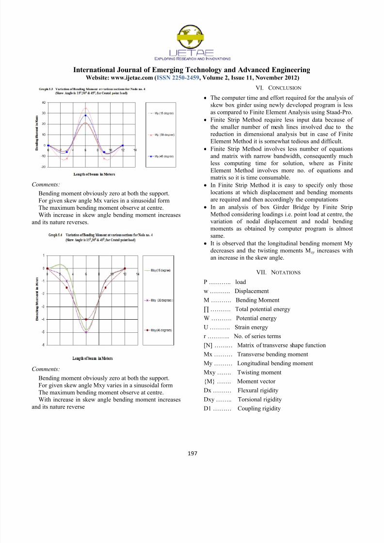
Comments:
Bending moment obviously zero at both the support.For given skew angle Mxy varies in a sinusoidal form
The maximum bending moment observe at centre.
With increase in skew angle bending moment increases
and its nature reverse
VI. CONCLUSION
The computer time and effort required for the analysis of
skew box girder using newly developed program is less
as compared to Finite Element Analysis using Staad-Pro.
Finite Strip Method require less input data because of
the smaller number of mesh lines involved due to the
reduction in dimensional analysis but in case of Finite
Element Method it is somewhat tedious and difficult.
Finite Strip Method involves less number of equations
and matrix with narrow bandwidth, consequently much
less computing time for solution, where as Finite
Element Method involves more no. of equations and
matrix so it is time consumable.
In Finite Strip Method it is easy to specify only those
locations at which displacement and bending momentsare required and then accordingly the computations
In an analysis of box Girder Bridge by Finite Strip
Method considering loadings i.e. point load at centre, the
variation of nodal displacement and nodal bending
moments as obtained by computer program is almost
same.
It is observed that the longitudinal bending moment My
decreases and the twisting moments M xy increases with
an increase in the skew angle.
VII.
NOTATIONS
P ……….. load
w ………. Displacement
M ………. Bending Moment
∏ ………. Total potential energy
W ………. Potential energy
U ………. Strain energy
r ……….. No. of series terms
[N] ……… Matrix of transverse shape function
Mx ……… Transverse bending moment
My ……… Longitudinal bending moment
Mxy ……. Twisting moment
{M} ……. Moment vector
Dx ……… Flexural rigidity
Dxy …….. Torsional rigidity
D1 ……… Coupling rigidity

7/18/2019 Analysis of Straight and Skewed Box Girder Bridge by Finite Strip Method
http://slidepdf.com/reader/full/analysis-of-straight-and-skewed-box-girder-bridge-by-finite-strip-method 8/8
International Journal of Emerging Technology and Advanced Engineering
Website: www.ijetae.com (ISSN 2250-2459, Volume 2, Issue 11, November 2012)
198
{K} …….. Stiffness matrix
{P} ……… Load vector
{ᵟ} ………. Curvature vector
s ………… no. of strips
t ………… is subscript representing the whole structure.
REFERENCE
[1 ]
Cheung Y.K. ( 1969) ―Analysis of box Girder Bridge by finite stripmethod‖ACI Publication, SP-26, 357-378
[2 ]
Finite Strip Method in Structural Analysis by Y.K.Cheung.
[3 ]
The Finite Strip Method in Bridge Engg. Dr. Yew-Chaye Loo
[4 ] Cheung M.S. , Georges Akhras. ( 1994) ―Combined boundaryelement/Finite strip analysis of bridges ―Journal of Structural
Engineering, ASCE, 120, 716-727.
[5 ]
Scordelis A.C. ( 1966) ―Analysis of simply supported box girder bridges‖SESM report 66-17, Univ. of California, Berkeley.
[6 ]
Cheung M.S. Cheung Y.K. ( 1971 ) ―Analysis of curved box girder
bridges by finite strip method‖ IABSE, 1-19
[7 ]
Finite Element method by C.S. Desai and J.F.Abel.
[8 ]
Buragohain D.N. ―Analysis of curved box girder bridges‖Structural
Division, ASCE, 99, 799-819
[9 ]
The Finite Element method by O.C.Zienkiewicz. and R.L.TaylorFourth edition (Volume 1)
[10 ]
Finite Element Analysis – Theory & Programming (Second Edition)By C.S. Krishnamurthy.
[11 ]
Matrix, Finite Element, Computer and Structural analysis By
Madhujit Mukhopadhyay.[12 ]
Matrix methods of structural analysis by Madhu B. Kanchi.
[13 ]
Combined boundary element / Finite strip analysis of bridges.
Journal of Structural Engineering ASCE, 120,716-727.
[14 ]
Analysis of Curved box girder bridges. Structural Division, ASCE,
99, 799-819
[15 ] Application of the Finite strip method in the analysis of concrete box
bridges ICJ, Jan 1994, 47-52
[16 ]
Essential of bridge – Vector.
[17 ]
Analysis of curved folded plate structures. ASCE, Structural
Division, 97, 2459-2480
[18 ]
Bridge Engineering by Phatak.
[19 ]
Design of Bridge Structures by T.R.Jagadesh & M.A.Jayaram.
[20 ]
Scordelis A.C. ( 1967) ―Analysis of Continuous box girder
bridges‖SESM report 67-25, Univ. of California, Berkeley
[21 ]
Concrete box girder bridges as sandwich plates. Structural Division
ASCE, 96, 2353-2371.
[22 ]
Behavior of Stiffened Curved plate model ASCE Vol.95, ST 11,
1959.
[23 ]
Cusens A R , Loo Y.C. (1974) Application of the Finite Strip
Method in the analysis of concrete box bridges ICE, 57,251-273
[24 ]
Finite Element Method for structural Engg. New age publications.