Embed Size (px)
Citation preview


Privacy and Personal Data Collection Disclosure
Certain features available in Trend Micro products collect and send feedback regarding product usage and detection information to Trend Micro. Some of this data is considered personal in certain jurisdictions and under certain regulations. If you do not want Trend Micro to collect personal data, you must ensure that you disable the related features.
The following link outlines the types of data that the Security Management System collects and provides detailed instructions on how to disable the specific features that feedback the information.
Legal Notice
© Copyright 2018 Trend Micro Incorporated. All rights reserved.
Trend Micro, the Trend Micro t-ball logo, TippingPoint, and Digital Vaccine are trademarks or registered trademarks of Trend Micro Incorporated. All other product or company names may be trademarks or registered trademarks of their owners.
Publication: December 2018
Data collected by Trend Micro is subject to the conditions stated in the Trend Micro Privacy Policy:
https://success.trendmicro.com/data-collection-disclosure
https://www.trendmicro.com/en_us/about/legal/privacy-policy-product.html

1
TPS deploymentThe Threat Protection System (TPS) helps protect your network by scanning, detecting, and responding to network trafficaccording to the filters, action sets, and global settings that you set up and maintain in the Local Security Manager (LSM)client. Each device provides intrusion prevention for your network according to the amount of network connections andhardware capabilities.
You can install a single TPS at the perimeter of your network, at the network core, on your intranet, or in all three locations.The following diagram shows an example of a corporate network with the TPS deployed to a variety of locations.
How the TPS protects your networkThe TPS contains a custom engine, the Threat Suppression Engine (TSE), that detects and blocks a broad range of attacks atwire speeds. The TSE is a flow-based network security engine, in which each packet is identified as a component of a flowand each flow is tracked in the connection table on the device. A flow is uniquely identified by its packet header information:
• IPv4 or IPv6 protocol (ICMP, TCP, UDP, other)
• source and destination IP addresses
• source and destination ports
The TSE reconstructs and inspects flow payloads by parsing the traffic at the application layer. When a packet matches anIPS filter, the device handles the packets based on the action set configured on the filter. For example, if the action set isBlock, then the packet is dropped and subsequent packets from the same flow are dropped without inspection. The deviceprovides default actions to block or permit traffic with options to quarantine or rate-limit traffic and to notify users orsystems when an action executes. Logging options are also available to review the types of traffic that the device filters. Youcan customize the default action sets, or create your own based on your network requirements.
Learn more about configuring filters.

TPS Local Security Manager User Guide
2
LSM prerequisitesBefore configuring the LSM, check the Release Notes for:
• a summary of new features included in the interface
• version-specific information
• browser and installation considerations
• late-breaking information that supersedes this document
Initial setup and installationBefore you can log in to the LSM web interface, complete the initial hardware installation and setup, and connect theappliance to the network. For instructions on installation and setup, see the detailed installation instructions for your product.
NoteThe device blocks traffic until it has completed the boot sequence.
TOS upgradesPlan TOS upgrades during a scheduled maintenance window.
Before you perform a TOS upgrade, consider the following:
• Refer to the TPS release notes for information specific to your TOS, including DV packages, migration, rollbacks, andtraffic interruptions.
• To avoid experiencing traffic interruption whenever the operating system is rebooted, perform a full reboot of thedevice by running the reboot full command from the device CLI. This issue is not applicable to vTPS devices.
• On vTPS devices, the flow of traffic is interrupted during a TOS upgrade and during a reboot of the device.
• An upgrade resets the authentication settings on your TPS device. If the authentication security level on your device wasset to Maximum, the upgrade resets the security level to Medium, which is the default security level. If necessary, updatethe security level to specify a higher security level. Learn more about authentication settings.
• Verify that a recent license package is installed on the device and if necessary, download and install a new license packagefrom the TMC. Without a recent license package, the device reverts to its unlicensed throughput.
• Maximize the space on your device by removing old TOS versions and packet traces. This ensures a successfulinstallation and allows for a TOS rollback, if necessary. You can remove previous TOS versions by using the SMS, theLSM, or the CLI. For complete information, refer to your product documentation.
Deploying a TPS deviceThe following guidelines provide important deployment information:
• Initial setup – After you power on, the setup wizard on the console port terminal runs through its initial checks andconfigurations.
• Powering on after a system shutdown – On the 440T TPS device only, after the device is shut down using the haltcommand, you must completely disconnect power—by unplugging the unit or by turning off the power switch on theback of the unit—for at least 60 seconds before attempting to power on the device again. For the 2200T and TX Series

TPS Local Security Manager User Guide
3
devices, power can be removed by holding down the front panel power button for 5 seconds, and restored by pressingthe power button.
• Traffic handling on initial setup – The device blocks traffic until the device has completed the boot sequence. Afterthe boot sequence completes, the device inspects traffic by using the Default inspection profile.
Important
On TX Series devices, any bypass I/O modules remain in bypass mode until you remove them from bypass mode through theCLI, LSM, or SMS. Rebooting the TPS does not change the bypass mode of the bypass I/O module.
• Device management – You can manage your TPS device using the Security Management System (SMS), Local SecurityManager (LSM), or the Command Line Interface (CLI).
Important
When you manage a TPS or vTPS device with the SMS, always distribute an inspection profile to all segments to beginprotecting network traffic. By default, when you add a vTPS or TPS device, all filter categories are disabled in the Defaultsecurity profile. When a TPS or vTPS device is unmanaged or deleted, there is no change in the filters. For information aboutdevice management, see the Security Management System User Guide.
• Virtual segments and IPS profiles – Rather than edit the settings in the default IPS profile, we recommend that youpreserve the default IPS profile. To apply your own IPS profile, create a copy of the default IPS profile and edit thevirtual segments.
• Idle timeout period – By default, when there has been no LSM or CLI activity for 15 minutes, connection to the devicetimes out. The idle timeout period was reduced from 60 minutes for improved security, and is configurable from theLSM (under Authentication > Authentication Settings) or from the CLI. From the aaa context, the login cli-inactive-timeout and login lsm-inactive-timeout commands configure the CLI and LSM timeout periods,respectively. For more information, see the Threat Protection System Command Line Interface Reference.
• Sending Tech Support Reports via email – If you encounter any issues, create a Tech Support Report (TSR) for eachissue you wish to submit. To send a TSR by email, use the following steps:
1. Create a TSR using the LSM (Tools > Tech Support Report). Or, from the CLI, use the tech-support-report command. If the TSR times out on the LSM, create a TSR from the CLI.
2. Use the LSM to export the file to your local system.
3. Contact Support to open a case and provide a detailed summary of the issue.
4. Send the TSR file as an email attachment to your corresponding Support agent.
Screen resolutionThe minimum screen resolution is 1366 x 768. For best results set your screen resolution to 1440 x 900. Lower resolutionsmight not fully display the contents of some LSM pages.
Logging in to the LSMThe TPS provides simultaneous support for up to 10 web client connections, 10 telnet/SSH (for CLI) connections, and oneconsole connection. You can also log in using the Command Line Interface (CLI).
After completing the installation steps—outlined in the detailed installation instructions for your product—log in to the LSMusing a supported browser.
TPS Local Security Manager User Guide
4
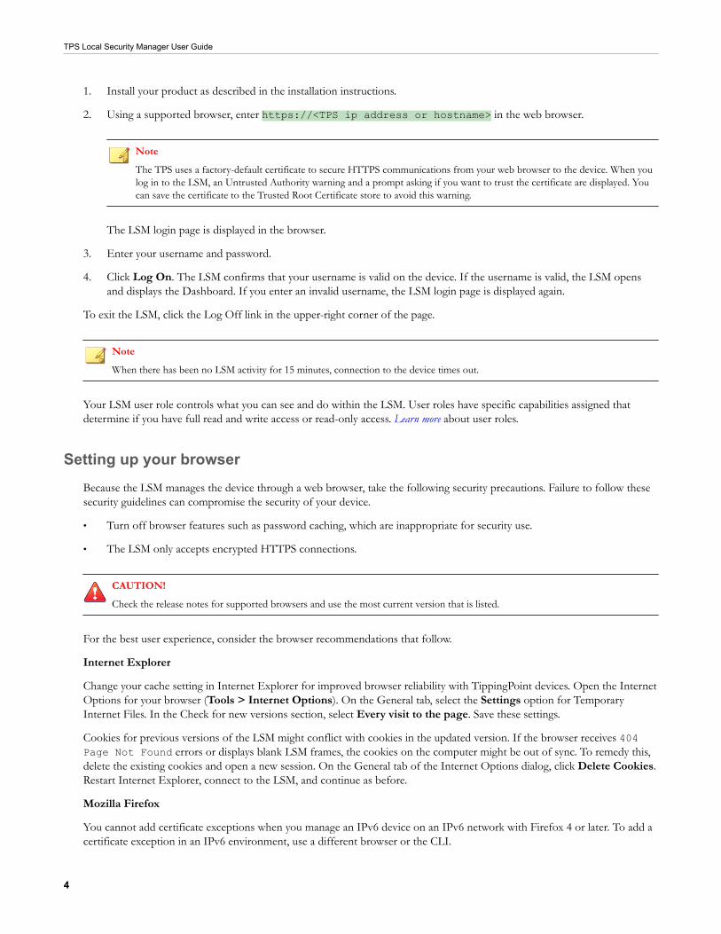
1. Install your product as described in the installation instructions.
2. Using a supported browser, enter https://<TPS ip address or hostname> in the web browser.
Note
The TPS uses a factory-default certificate to secure HTTPS communications from your web browser to the device. When youlog in to the LSM, an Untrusted Authority warning and a prompt asking if you want to trust the certificate are displayed. Youcan save the certificate to the Trusted Root Certificate store to avoid this warning.
The LSM login page is displayed in the browser.
3. Enter your username and password.
4. Click Log On. The LSM confirms that your username is valid on the device. If the username is valid, the LSM opensand displays the Dashboard. If you enter an invalid username, the LSM login page is displayed again.
To exit the LSM, click the Log Off link in the upper-right corner of the page.
Note
When there has been no LSM activity for 15 minutes, connection to the device times out.
Your LSM user role controls what you can see and do within the LSM. User roles have specific capabilities assigned thatdetermine if you have full read and write access or read-only access. Learn more about user roles.
Setting up your browserBecause the LSM manages the device through a web browser, take the following security precautions. Failure to follow thesesecurity guidelines can compromise the security of your device.
• Turn off browser features such as password caching, which are inappropriate for security use.
• The LSM only accepts encrypted HTTPS connections.
CAUTION!
Check the release notes for supported browsers and use the most current version that is listed.
For the best user experience, consider the browser recommendations that follow.
Internet Explorer
Change your cache setting in Internet Explorer for improved browser reliability with TippingPoint devices. Open the InternetOptions for your browser (Tools > Internet Options). On the General tab, select the Settings option for TemporaryInternet Files. In the Check for new versions section, select Every visit to the page. Save these settings.
Cookies for previous versions of the LSM might conflict with cookies in the updated version. If the browser receives 404Page Not Found errors or displays blank LSM frames, the cookies on the computer might be out of sync. To remedy this,delete the existing cookies and open a new session. On the General tab of the Internet Options dialog, click Delete Cookies.Restart Internet Explorer, connect to the LSM, and continue as before.
Mozilla Firefox
You cannot add certificate exceptions when you manage an IPv6 device on an IPv6 network with Firefox 4 or later. To add acertificate exception in an IPv6 environment, use a different browser or the CLI.

TPS Local Security Manager User Guide
5
If your browser receives 404 Page Not Found errors or displays blank LSM frames, the cookies on the computer mightbe out of sync. To resolve these issues, clear the cache, delete the cookies, and restart the browser.
Pop-Up Blocking
If your browser has pop-up blocking enabled, some elements in the LSM might not display correctly. Enable pop-ups for theLSM by adding the device’s URL to the browser pop-up whitelist.
Working with filtersThe TPS uses Digital Vaccine (DV) filters to police your network and to screen out malicious or unwanted traffic. In additionto the DV filters, the TPS also provides Traffic Management filters, which are custom filters that react to traffic based onsource IP address, destination IP address, port, protocol, or other defined values. Traffic management filters are applied totraffic before DV filters. Depending on how the filters are configured, traffic might require further inspection.
The Digital Vaccine packageDV filters are contained in a DV package. Your TPS comes with a DV package installed and configured so that your networkcan be protected as soon as you start the device. After setting up the TPS, you can still customize the filters in the DVthrough the LSM. To ensure that you have the most up-to-date DV package, download the latest package from the Updatepage in the LSM. Learn more about updating your device.
The filters within the DV package are designed to protect the network from specific exploits and to adjust for attackpermutations of Zero Day Initiative (ZDI) threats. These filters include traffic anomaly filters and vulnerability-based filters.Vulnerability-based filters are designed to protect the network from an attack that takes advantage of a weakness inapplication software. For viruses that are not based on a specific vulnerability in software, the DV provides signature filters.
DV updates occur regularly. When a critical vulnerability or threat is discovered, DV updates and distributions occurimmediately. Learn more about how to configure your TPS device to automatically receive these updates (System > Update).
Tip
In addition to providing a download location for DV packages, the TMC also provides DV product documentation that includesmore detailed information about the filters included in the DV package, filter updates, and other related information.
For organizations that experience heavier risk factors for threats that go beyond the scope of the standard DV coverage,additional subscription services are available. These services include:
• Reputation Feed — provides reputation filters for suspect IP addresses and domains.
• Malware Filter Package — provides advanced malware protection.
To register for a DV subscription service, contact your customer representative.
Filter componentsTPS filters have the following components, which determine the filter type, global and customized settings, and how thesystem responds when the TSE finds traffic matching the filter:
• Category — Defines the type of network protection that the filter provides. This category also enables you to locate thefilter and control the global filter settings using the Category Setting configuration.
• Action set — Defines what occurs when the system detects traffic that matches the filter.

TPS Local Security Manager User Guide
6
• Adaptive Filter Configuration State — Enables you to override the global Adaptive Filter configuration settings sothat adaptive filtering does not affect the filter. Learn more about adaptive filtering.
• State — Indicates if the filter is enabled or disabled.
Category settingsUse category settings to configure global settings for all filters within a specified category group. DV filters are organized intogroups based on the type of protection provided:
• Application Protection Filters defend against known exploits and exploits that can take advantage of knownvulnerabilities targeting applications and operating systems. This filter type includes the subcategories Exploits, IdentityTheft, Reconnaissance, Security Policy, Spyware, Virus, and Vulnerabilities.
• Infrastructure Protection Filters use protocols and detect statistical anomalies to protect network bandwidth andnetwork infrastructure elements (such as routers and firewalls). This filter type includes the subcategories NetworkEquipment and Traffic Normalization.
• Performance Protection Filters block or rate-limit traffic from applications that can consume excessive bandwidth,leaving network resources available for use by key applications. This filter type includes the subcategories IM, P2P, andStreaming Media.
Use category settings to assign global configuration settings to filters in a subcategory. For example, if you decide not to useany filters to monitor P2P traffic, you can change the category settings for the Performance Protection P2P filter group todisable these filters. Category settings consist of the following global parameters:
• State — Determines whether filters within the subcategory are enabled or disabled. If you disable a category, youdisable all filters in the category.
• Action Set — Determines what occurs when traffic matches a filter. If you configure the Recommended action set,filters within the category are configured with the settings that the DV team recommends. If required, you can overridethe category setting on individual filters by editing the filter to define custom settings.
Filter override settingsFor the best system performance, use global category settings and the Recommended action set for all DV filters. However,in some cases, you might need to override the category settings and recommended action for individual filters because ofspecific network requirements, or in cases where the recommended settings for a filter interact poorly with your network.
Filter override settings apply custom settings to the filter in the Security Profile. After you customize a filter, the globalCategory Settings that specify the filter State and Action does not affect it.
Filter limits and exceptionsLimits and exceptions change the way filters are applied based on IP address. For example, you can specify a limit setting sothat filters only apply to specific source and destination IP addresses or address ranges. If a filter has both global and filter-level exception settings, the TSE uses the filter-level settings to determine how to apply the filter. You can configure thefollowing limits and exceptions from the LSM:
• Filter Exceptions (specific) — Allow traffic to pass between specific addresses or address ranges without triggering afilter that would normally be triggered. Configured from the Filter Edit page, these exceptions apply only to the filterthat specifies them.
• Limit Filter to IP Addresses (global) — Only apply filters to traffic between specified source and destination IPaddress pairs. You can configure IP address limits that apply to Application Protection, Traffic Normalization, and
TPS Local Security Manager User Guide
7
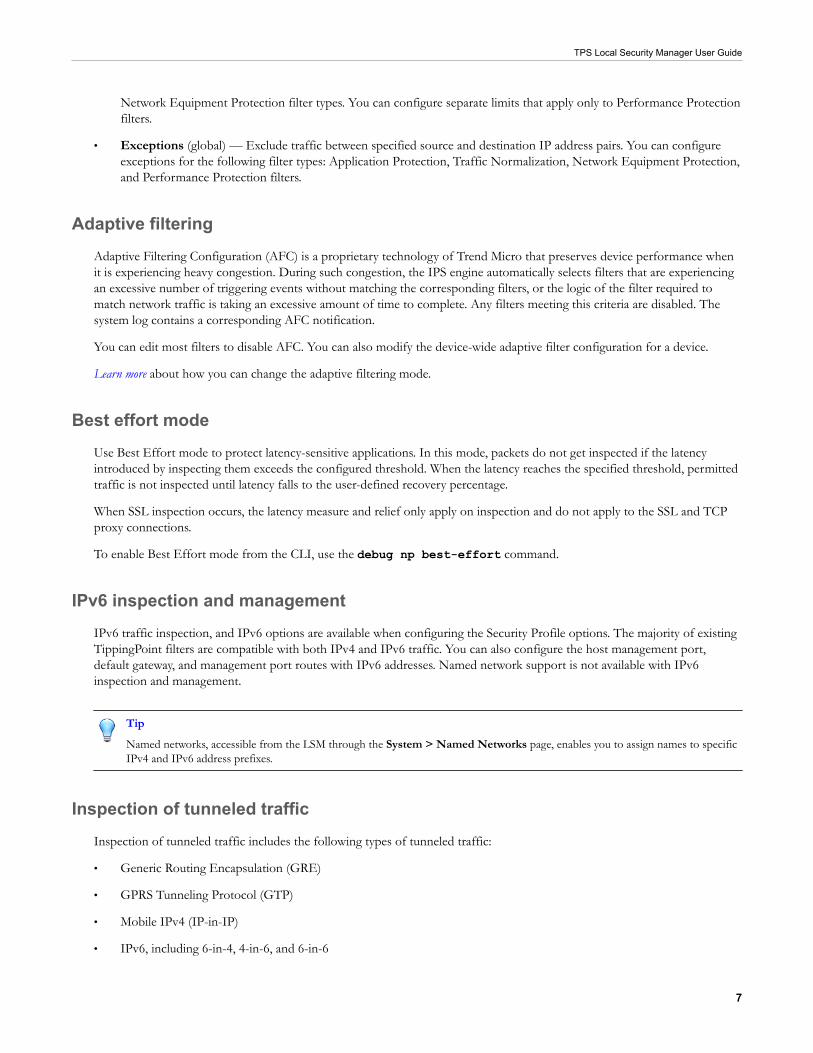
Network Equipment Protection filter types. You can configure separate limits that apply only to Performance Protectionfilters.
• Exceptions (global) — Exclude traffic between specified source and destination IP address pairs. You can configureexceptions for the following filter types: Application Protection, Traffic Normalization, Network Equipment Protection,and Performance Protection filters.
Adaptive filteringAdaptive Filtering Configuration (AFC) is a proprietary technology of Trend Micro that preserves device performance whenit is experiencing heavy congestion. During such congestion, the IPS engine automatically selects filters that are experiencingan excessive number of triggering events without matching the corresponding filters, or the logic of the filter required tomatch network traffic is taking an excessive amount of time to complete. Any filters meeting this criteria are disabled. Thesystem log contains a corresponding AFC notification.
You can edit most filters to disable AFC. You can also modify the device-wide adaptive filter configuration for a device.
Learn more about how you can change the adaptive filtering mode.
Best effort modeUse Best Effort mode to protect latency-sensitive applications. In this mode, packets do not get inspected if the latencyintroduced by inspecting them exceeds the configured threshold. When the latency reaches the specified threshold, permittedtraffic is not inspected until latency falls to the user-defined recovery percentage.
When SSL inspection occurs, the latency measure and relief only apply on inspection and do not apply to the SSL and TCPproxy connections.
To enable Best Effort mode from the CLI, use the debug np best-effort command.
IPv6 inspection and managementIPv6 traffic inspection, and IPv6 options are available when configuring the Security Profile options. The majority of existingTippingPoint filters are compatible with both IPv4 and IPv6 traffic. You can also configure the host management port,default gateway, and management port routes with IPv6 addresses. Named network support is not available with IPv6inspection and management.
Tip
Named networks, accessible from the LSM through the System > Named Networks page, enables you to assign names to specificIPv4 and IPv6 address prefixes.
Inspection of tunneled trafficInspection of tunneled traffic includes the following types of tunneled traffic:
• Generic Routing Encapsulation (GRE)
• GPRS Tunneling Protocol (GTP)
• Mobile IPv4 (IP-in-IP)
• IPv6, including 6-in-4, 4-in-6, and 6-in-6
TPS Local Security Manager User Guide
8
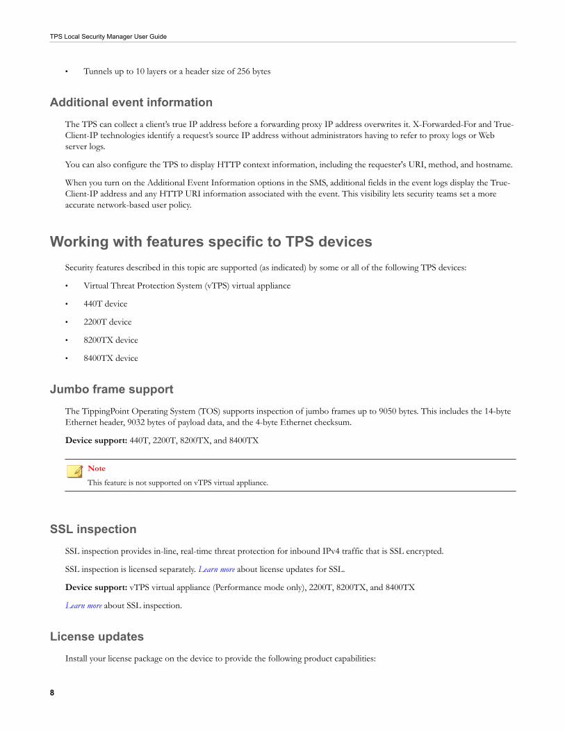
• Tunnels up to 10 layers or a header size of 256 bytes
Additional event informationThe TPS can collect a client’s true IP address before a forwarding proxy IP address overwrites it. X-Forwarded-For and True-Client-IP technologies identify a request’s source IP address without administrators having to refer to proxy logs or Webserver logs.
You can also configure the TPS to display HTTP context information, including the requester's URI, method, and hostname.
When you turn on the Additional Event Information options in the SMS, additional fields in the event logs display the True-Client-IP address and any HTTP URI information associated with the event. This visibility lets security teams set a moreaccurate network-based user policy.
Working with features specific to TPS devicesSecurity features described in this topic are supported (as indicated) by some or all of the following TPS devices:
• Virtual Threat Protection System (vTPS) virtual appliance
• 440T device
• 2200T device
• 8200TX device
• 8400TX device
Jumbo frame supportThe TippingPoint Operating System (TOS) supports inspection of jumbo frames up to 9050 bytes. This includes the 14-byteEthernet header, 9032 bytes of payload data, and the 4-byte Ethernet checksum.
Device support: 440T, 2200T, 8200TX, and 8400TX
NoteThis feature is not supported on vTPS virtual appliance.
SSL inspectionSSL inspection provides in-line, real-time threat protection for inbound IPv4 traffic that is SSL encrypted.
SSL inspection is licensed separately. Learn more about license updates for SSL.
Device support: vTPS virtual appliance (Performance mode only), 2200T, 8200TX, and 8400TX
Learn more about SSL inspection.
License updatesInstall your license package on the device to provide the following product capabilities:

TPS Local Security Manager User Guide
9
• Inspection throughput
• Digital Vaccine
• ThreatDV
• SSL inspection
Not all product capabilities are supported on all TPS devices.
Verify your product license provides sufficient inspection throughput. By default, a TPS security device is unlicensed andprovides reduced inspection throughput for testing and evaluation purposes only.
Security device Unlicensed inspection throughput
vTPS 100 Mbps
440T 100 Mbps
2200T 200 Mbps
8200TX 1 Gbps
8400TX 1 Gbps
Learn more about updating the license package.
Device support: vTPS virtual appliance, 440T, 2200T, 8200TX, and 8400TX devices
VLAN translation
VLAN translation enables the TPS to selectively inspect traffic based on the configuration of the aggregation or distributionswitch. This feature translates traffic between different VLANs or between VLAN and non-VLAN interfaces.
Device support: 440T, 2200T, 8200TX, and 8400TX devices
Note
This feature cannot be enabled on vTPS virtual appliances.
Learn more about VLAN translation.
Inspection bypass rules
Inspection bypass rules describe traffic to be directed through the TPS device without inspection. You can apply these rulesto traffic according to source or destination IP address, port, or CIDR (Classless Inter-Domain Routing), or to traffic movingthrough specific ports.
Device support: 440T, 2200T, 8200TX, and 8400TX devices
Note
This feature is not supported on vTPS virtual appliances.
Learn more about inspection bypass rules.

TPS Local Security Manager User Guide
10
sFlow® record emissionThe NX-Platform devices and TPS devices use sFlow record emission to sample a random flow of traffic and send the datato a collector server for analysis. The analysis gives security teams a more holistic view of traffic patterns, which enables earlydetection and remediation of anomalous or malicious flows.
With sFlow sampling, network and security administrators establish a baseline of typical application traffic to identify unusualpatterns. Users specify the following information:
• The IP address of the collection repository. Two collector IP addresses (either IPv4 or IPv6) are supported for IPSdevices with TOS v3.6.0 and later installed, and for TPS devices with TOS v5.0.0 and later installed.
• The network segments that have this feature enabled. Although you can enable or disable sampling globally, you stillmust configure the rate on a per-segment basis.
• The sample rate. Configure this rate at the segment level. Faster links enable larger sample rates.
Tip
Segments for NX-Platform and TX Series devices are on the I/O modules. When you remove a module from a slot, the module'ssegment configuration and the availability state of its ports remain unchanged. For this reason, consider disabling sFlow on themodule's segment port before removing the module. This prevents the device from sending extraneous port statistics counters toany configured sFlow collectors.
The data that is sampled is sent as an sFlow datagram packet to the collector server where analysis occurs. You can thengenerate reports, including comparison charts, that provide visibility of network congestion and potential security incidents,thereby enhancing the scalability of the network. The SMS can perform data analysis using the SMS Collector.
Note
The option for sFlow sampling is supported on NX-Platform devices and TPS devices only. Learn more about configuring sFlow onsegments and learn more about configuring an sFlow collector.
Device support: NX-Platform devices and all TPS devices
Note
This feature is not supported on vTPS virtual appliances.
Provider Backbone Bridging (MAC-in-MAC) supportThe TippingPoint TX Series devices protect your MAC-in-MAC encapsulated traffic that follows the IEEE 802.1ah standard.Consider these points:
• Network protection is limited to the least significant 20 bits of the 24-bit service identifier (I-SID). The TPS cannoteffectively inspect MAC-in-MAC traffic if your network uses the most significant four bits in the I-SID to form differentMAC-in-MAC provider domains.
• You can verify the device recognizes MAC-in-MAC traffic by running the debug np stats shownpParseStatsInst CLI command on the device or by taking a packet capture. When you configure the packetcapture, specify a TCPDump expression that identifies the Backbone MAC address (B-MAC) or Backbone VLANidentifier (B-VID) of the traffic you want, or capture all packets for a particular segment.
Device support: 8200TX and 8400TX devices

TPS Local Security Manager User Guide
11
Changing configurationsThe Start configuration determines the last known configuration of the device and is automatically applied when you reboot thedevice.
The Running configuration is the Start Configuration plus any committed changes from all users of the device since the lastreboot. When you log in to the LSM, it loads the Running configuration. When users commit their configuration changes, orwhen changes are committed automatically, the changes are committed to the Running configuration only, and the changesare visible to all users.
However, when the device reboots, the Running configuration is reset to the Start configuration. Uncommitted changes andcommitted changes in the Running configuration are lost.
If you want to persist your Running configuration changes across reboots, you must copy the Running configuration to theStart configuration.
• For a running configuration with only committed changes, select Configuration > Copy Running Configuration toStart.
• For a running configuration with both uncommitted and committed changes, select Configuration > Commitpending changes and copy to Start.
For your convenience, the LSM displays the pending changes count on the Configuration menu. You lose any pendingchanges that are saved but not committed when you exit the LSM. Commit changes to inspection profiles using either theLSM or the SMS.
Deferred commitYou can use a deferred commit if you do not want any of your changes to apply immediately to your current configuration.You defer these changes (place them into a pending state) until you explicitly commit them. Each time you open the LSM, acopy of the configuration is created.
NoteIf no changes are pending in the LSM, any deferred commit changes made by the SMS or CLI are displayed when you manuallyrefresh the screen or navigate to a different screen.
Perform the following sequence to ensure that a configuration is active:

TPS Local Security Manager User Guide
12
1. Make changes to your configuration.
2. Commit the changes to the currently active session.
3. (Optional) Copy the changes to the Start Configuration to persist them after the active session closes.
Deferring changes enables you to make and test changes before they become permanent. This way you can back out of orrecover from any unexpected results of a configuration change. It also prevents a partial configuration. For example, if youcreate a new Zone, you must also create a new policy for that Zone or modify an existing policy to protect it. With deferredcommits, you can complete each of the associated tasks and then commit the changes at one time.
View and discard Pending changes
Uncommitted changes are placed into a Pending state until you explicitly commit them to the Running configuration. If youlog out of the LSM without committing your Pending changes, you lose those changes.
DashboardTo quickly assess policy and system performance, first view the Dashboard. This page is displayed each time you log in to theLSM.
For example, the Health panel includes color health indicators for various components that you can use to get the currentstate of each component's performance:
• Green — No problems
• Yellow — Major warning
• Red — Critical warning
• Grey — Service is disabled
Click Major and Critical warning indicators to view the error that caused the condition. When you view the error, theindicator is reset and its color changes back to green.
For detailed information about each of the health indicators, click on the corresponding links or navigate to the item usingthe Monitor menu.
You can access the Dashboard at any time by clicking the Home icon on the left side of the menu bar.
Monitor the deviceMonitor logs, sessions, health, and network status using the Monitor menu. It provides administrative control of user sessions,to view or clear all or specific sessions. The XML-based APIs provided at the back end retrieve all the data for all the sessions.
You can initiate some monitor requests by specifying attributes such as IP addresses, family, port numbers, or protocol. Otherrequests do not require specifying any attributes.
The columns in the table vary according to the type of report. You can click a heading to sort the table by the column. Youcan cycle through two sort orders by clicking the column heading: ascending (down arrow) and descending (up arrow). Youcan click on the Columns list to check or uncheck the rows to be included or excluded in the table menu.

TPS Local Security Manager User Guide
13
Monitor logsIn addition to viewing logs, you can also search for logs, sort logs by the newest or oldest entry, download a local copy, andclear log entries.
Use the Monitor menu for surveillance of the following logs:
• Audit logs
• System logs
• IPS Block and Alert logs
• Quarantine logs
• Reputation Block and Alert logs
• SSL inspection logs
For the logs that have them, the severity states are as follows:
• 4: Critical
• 3: Major
• 2: Minor
• 1: Low
When the log is downloaded, the severity is indicated with a number.
Audit logsThe Audit log tracks user activity that might have security implications, including user attempts (successful and unsuccessful),to do the following:
• Change user information
• Change routing or network configuration
• Gain access to controlled areas (including the audit log)
• Update system software and attack protection filter packages
• Change filter settings
When the audit log data threshold reaches 75%, an alert is generated (not configurable). To maintain a complete history ofentries and provide a backup, you can configure the device to send log entries to a remote syslog server from the System >Log Configuration > Notification Contacts page.
Note
Only users with SuperUser access level can view, print, reset, and download the Audit log.
The Audit Logs table includes the following information:
Column Description
User Displays the login name of the user who performed the audited action. The user listed for anevent can include SMS, SYS, and CLI.
TPS Local Security Manager User Guide
14
Column Description
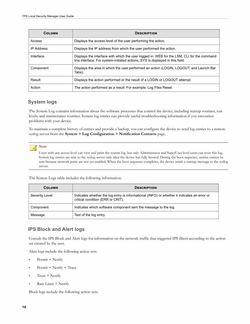
Access Displays the access level of the user performing the action.
IP Address Displays the IP address from which the user performed the action.
Interface Displays the interface with which the user logged in: WEB for the LSM, CLI for the commandline interface. For system-initiated actions, SYS is displayed in this field.
Component Displays the area in which the user performed an action (LOGIN, LOGOUT, and Launch BarTabs).
Result Displays the action performed or the result of a LOGIN or LOGOUT attempt.
Action The action performed as a result. For example, Log Files Reset.
System logsThe System Log contains information about the software processes that control the device, including startup routines, runlevels, and maintenance routines. System log entries can provide useful troubleshooting information if you encounterproblems with your device.
To maintain a complete history of entries and provide a backup, you can configure the device to send log entries to a remotesyslog server from the System > Log Configuration > Notification Contacts page.
Note
Users with any access level can view and print the system log, but only Administrator and SuperUser level users can reset this log.System log entries are sent to the syslog server only after the device has fully booted. During the boot sequence, entries cannot besent because network ports are not yet enabled. When the boot sequence completes, the device sends a startup message to the syslogserver.
The System Logs table includes the following information:
Column Description
Severity Level Indicates whether the log entry is informational (INFO) or whether it indicates an error orcritical condition (ERR or CRIT).
Component Indicates which software component sent the message to the log.
Message Text of the log entry.
IPS Block and Alert logsConsult the IPS Block and Alert logs for information on the network traffic that triggered IPS filters according to the actionset created by the user.
Alert logs include the following action sets:
• Permit + Notify
• Permit + Notify + Trace
• Trust + Notify
• Rate Limit + Notify
Block logs include the following action sets:

TPS Local Security Manager User Guide
15
• Block + Notify
• Block + Notify + Trace
The logs contain IP and Layer 4 information, along with the matching filter.
To maintain a complete history of entries and provide a backup, you can configure the device to send log entries to a remotesyslog server from the System > Log Configuration > Notification Contacts page.
NoteAny user can view the log, but only administrator and SuperUser level users can reset the log.
The IPS Logs tables include the following information:
Column Description
Action Indicates the action that triggered the alert.
Filter Name Displays the name of the filter that was matched.
Rate Limit (Alert Log only) Displays the rate limit. If applicable, the log displays the rate limiter rate thatwas defined in the triggered action set. The log also displays a link to the action set on whichthe log entry was generated. This field is blank for Permit and Trust action log entries.
Protocol Displays the name of the protocol that the action affects.
Interface In Displays the network interface on which the traffic arrived.
Src Addr Displays the source address of the triggering traffic.
Src Port Displays the source port number of the triggering traffic.
Interface Out Displays the network interface from which the triggering traffic departed.
Dst Addr Displays the destination address of the triggering traffic.
Dst Port Displays the destination port number of the triggering traffic.
Virtual Segment Displays the virtual segment on which the alert or block occurred (such as 1A-1B).
VLAN ID Displays the identification number of the VLAN.
Client IP Displays the True-Client-IP address. Client IP (X-Forwarded-For & True-Client-IP) featuremust be enabled.
URI Displays the HTTP URI. HTTP Context (Hostname, URI, method) feature must be enabled.
Method Displays the HTTP method to be performed on the identified resource. HTTP Context(Hostname, URI, method) feature must be enabled. The following methods are supported:GET, PUT, POST, HEAD, DELETE, OPTIONS, TRACE, and CONNECT.
Hostname Distinguishes between various DNS names that share an IP address. HTTP Context(Hostname, URI, method) feature must be enabled.
Hit Count Displays the number of packets that have been detected if packet tracing is enabled.
Packet Trace Indicates whether packet tracing is enabled.
Quarantine logsThe Quarantine log records the IP addresses that have been added to and removed from quarantine. Quarantine loggingoperates independently of a policy’s notification contacts. Quarantine events are always recorded in a log file and on theremote syslog server if configured to do so.

TPS Local Security Manager User Guide
16
Note
Any user can view the log, but only administrator and SuperUser level users can reset the log.
The Quarantine Logs table includes the following information:
Column Description
Interface In Displays the network interface on which the traffic arrived.
Src Addr Displays the source address of the triggering traffic.
Action Indicates whether the IP address was added or removed to the Quarantine logs.
Filter Name Displays the name of the filter that was matched.
Reputation Block and Alert logsThe Reputation log contains log messages for the network traffic that triggers a reputation filter configured with the actionset created by the user. Alert messages are displayed for network traffic that triggered a reputation filter configured with thePermit + Notify action set. Block messages are displayed for network traffic that triggered a reputation filter configured withthe Block + Notify action set.
The Reputation Logs tables include the following information:
Column Description
Action Indicates whether the IP address was added or removed to the reputation logs.
Filter Name Displays the name of the filter that was matched.
Rate Limit (Alert Log only) Displays the rate limit. If applicable, the log displays the rate limiter rate thatwas defined in the triggered action set. The log also displays a link to the action set on whichthe log entry was generated. This field is blank for Permit and Trust action log entries.
Protocol Displays the name of the protocol that the action affects.
Interface In Displays the network interface on which the traffic arrived.
Src Addr Displays the source address of the triggering traffic.
Src Port Displays the source port number of the triggering traffic.
Interface Out Displays the network interface from which the triggering traffic departed.
Dst Addr Displays the destination address of the triggering traffic.
Dst Port Displays the destination port number of the triggering traffic.
Virtual Segment Displays the virtual segment on which the alert or block occurred (such as 1A-1B).
VLAN ID Displays the identification number of the VLAN.
Hit Count Displays the number of packets that have been detected if packet trace is enabled.
Packet Trace Indicates whether packet tracing is enabled.
SSL inspection logsThe SSL Inspection Log records information about SSL sessions. For details, such as connection resets, select Columns >Details.

TPS Local Security Manager User Guide
17
Monitor user sessionsTo view all the currently logged users, locked users, and user IP addresses, select Monitor > Sessions > Users. If thenumber of login attempts from a specific user or the IP address exceeds the maximum login attempts, the system locks outthe user or IP address.
• To view all the currently logged users, select Monitor > Users > Active Users.
Note
Multiple LSM user sessions from the same IP address are not tracked if a user logs in several times from the same IP address.
• To view all the users who are currently locked out, select Monitor > Users > Locked Users / IP Addresses. Tounlock the user, select the checkbox next to the Username or IP Address and click Unlock.
Monitor managed streamsFrom the Monitor menu, you can also monitor security events. These pages provide visibility into inspection results andtraffic flows, including the following sessions:
• Blocked streams
• Rate-limited streams
• Quarantined addresses
• Trusted streams
Blocked streams
When traffic triggers a filter that has been configured with a Block or Block + Notify action, traffic from the source IPaddress and port is blocked and an entry is added to the Blocked Streams table, based on the contact configuration in theaction set. Only the IPS blocks and IP reputation (not DNS) can create a block entry.
From the Blocked Streams page, you can:
• View and search for information on blocked streams
• Manually clear all or selected blocked stream connections
The Blocked Streams table displays up to 50 entries. Entries are added when the block event occurs. Entries are automaticallyremoved when the connection times out based on the Connection Table timeout setting configured from the Policy >Profiles > Settings page. You can manually remove an entry from the table with the Flush function, which unblocks thestream.
View blocked streams
Procedure
1. Select Monitor > Blocked Streams.
2. To block the stream, select the checkbox next to the stream and click Flush Selected or Flush All. On theconfirmation dialog, click OK.
To quickly locate a specific blocked stream, use the search panel on the upper-right of the page.

TPS Local Security Manager User Guide
18
Rate-limited streamsWhen traffic triggers a filter configured with a rate-limit action set, traffic from the source IP and port is limited based on therate-limit settings. Traffic from the source IP address and port to the destination IP address and port remains rate-limiteduntil the connection time-out period expires, or until the connection is manually terminated.
From the Rate Limited Streams page, you can:
• View and search for information on rate-limited streams
• Manually terminate all or selected rate-limited stream connections
The Rate Limited Streams table displays up to 50 entries. Entries are added when the rate-limit event occurs. Entries areautomatically removed when the connection times out based on the Connection Table setting configured from the Policy >Profiles > Settings page. You can manually remove an entry with the Flush functions, which removes the rate limit from thestream.
View rate-limited streams
Procedure
1. Select Monitor > Rate Limited Streams.
2. To rate-limit the stream, select the checkbox next to the stream and click Flush Selected or Flush All. On theconfirmation dialog, click OK.
Quarantined addressesWhen traffic triggers a filter that has been configured with a quarantine action, the host is quarantined and an entry is addedto the Quarantined Addresses table, based on the contact configuration in the action set. From the Quarantined Addressespage, you can:
• Manually force an address into quarantine
• Search for quarantined addresses
• Manually release all or selected quarantined hosts
The Quarantined Addresses table displays up to 50 entries, including for each entry the IP/source addresses, networkdestination, and reason for the quarantine.
Manually force an IP address into quarantine
Procedure
1. Enter the IP address in the IP Address to Quarantine field.
2. Select the action set from the Action list.
3. Click Quarantine to add the IP address to the quarantined addresses table.
To search for a specific IP address:
• Enter the IP address in the Search IP Address field.
• Click Go to view the generated report or Clear to clear the search panel.
TPS Local Security Manager User Guide
19
Trusted streamsWhen traffic triggers a filter configured with a Trust action set, traffic from the source IP and port is recorded in the TrustedStreams table. From the Trusted Streams page, you can:
• View and search for information on trusted streams
• Manually clear all or selected trusted stream connections
The Trusted Streams table displays up to 50 entries, including for each entry the source/destination of addresses, ports, andinterfaces, as well as the reason for the stream being trusted.
Entries are added when the trust action occurs. Entries are automatically removed when the connection times out based onthe Trusted Streams flush setting configured from the Policy > Profiles > Settings page. You can manually remove anentry with the Flush functions, which removes the trusted stream from the table.
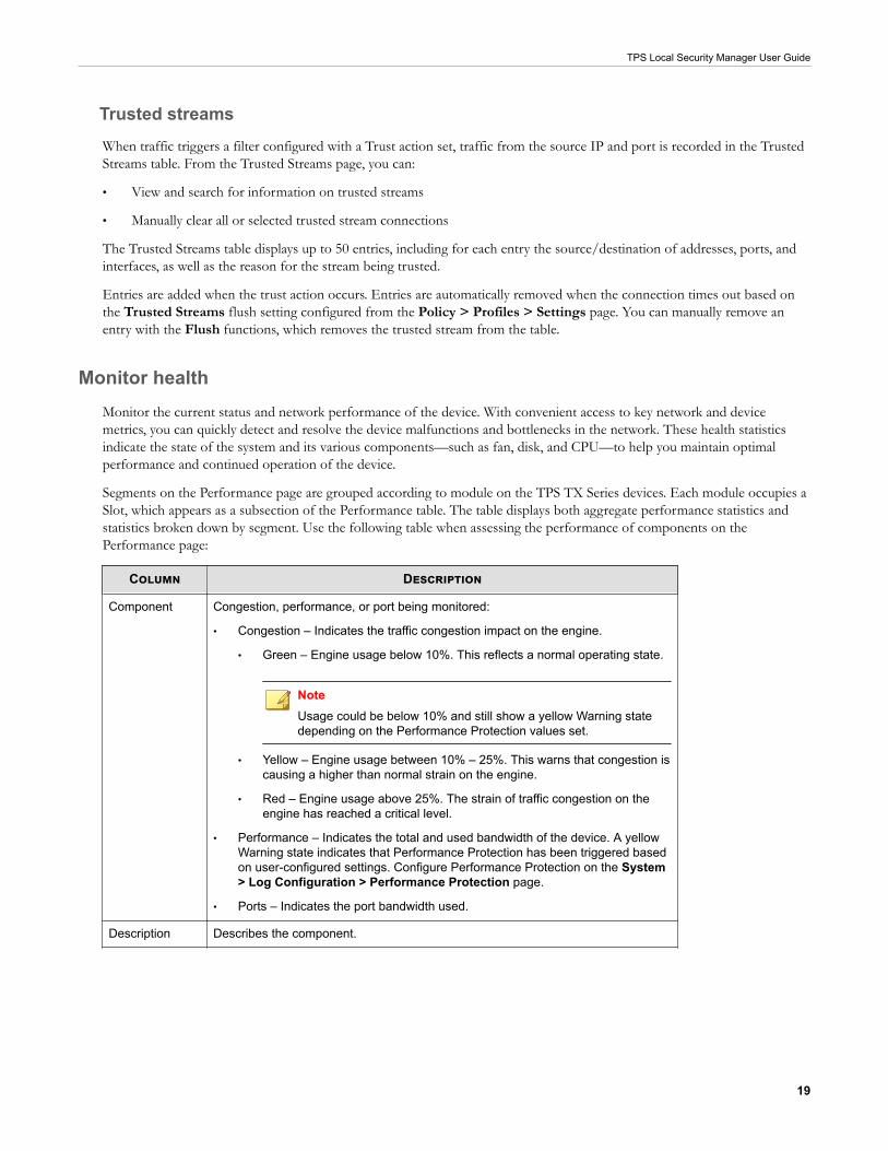
Monitor healthMonitor the current status and network performance of the device. With convenient access to key network and devicemetrics, you can quickly detect and resolve the device malfunctions and bottlenecks in the network. These health statisticsindicate the state of the system and its various components—such as fan, disk, and CPU—to help you maintain optimalperformance and continued operation of the device.
Segments on the Performance page are grouped according to module on the TPS TX Series devices. Each module occupies aSlot, which appears as a subsection of the Performance table. The table displays both aggregate performance statistics andstatistics broken down by segment. Use the following table when assessing the performance of components on thePerformance page:
Column Description
Component Congestion, performance, or port being monitored:
• Congestion – Indicates the traffic congestion impact on the engine.
• Green – Engine usage below 10%. This reflects a normal operating state.
NoteUsage could be below 10% and still show a yellow Warning statedepending on the Performance Protection values set.
• Yellow – Engine usage between 10% – 25%. This warns that congestion iscausing a higher than normal strain on the engine.
• Red – Engine usage above 25%. The strain of traffic congestion on theengine has reached a critical level.
• Performance – Indicates the total and used bandwidth of the device. A yellowWarning state indicates that Performance Protection has been triggered basedon user-configured settings. Configure Performance Protection on the System> Log Configuration > Performance Protection page.
• Ports – Indicates the port bandwidth used.
Description Describes the component.

TPS Local Security Manager User Guide
20
Column Description
State The current performance status of the device or the operating status of each port.
• Normal — Green. Device performance is normal. The port is active withouterrors.
• Warning — Yellow. Performance loss or congestion has put undue stress onthe engine or has triggered Performance Protection mode.
• Critical — Red. The port is waiting for traffic or usage in a stand-by mode, orthe device has entered Layer 2 Fallback because of Performance Protection.
• Inactive — Grey. The port is not in use or is disabled.
Throughput A bar graph depicting the performance of the device and current usage level of theports.
• Performance – Indicates the total and used bandwidth of the device. The colorof the bar changes according to the status of Performance Protection.
• <Port name>
• Green – Less than 80% of port bandwidth used.
• Yellow – Between 80% and 99% of port bandwidth used.
• Red – Over 99% of port bandwidth used.
Details Percentage of throughput used.
The HA page displays identifying information for your device and its HA partner device. The State Synchronization tabledisplays each subsystem and its current state. You can force a subsystem state resync by selecting the check box next to theSubsystem and clicking Force State Re-Sync.
The High Availability page lists the current high availability status for the following High Availability features:
• Intrinsic Network High Availability
• Transparent High Availability
Learn more about configuring HA.
Monitor networkUse the Monitor menu to survey network performance, such as bandwidth and traffic (in bps) activity of the ports.
Ports refer to the physical ports on the device such as 1A, 1B, and so on. On TX Series devices, ports are grouped by module.Each module occupies a slot, and the number of the slot is reflected in the port name. For example, port 3A in the moduleinserted in slot 2 would be listed as 2-3A. The available trend intervals are 24 hours, seven days, and 30 days.
NetworkTo view and modify the setup of the device so that it can work within your network environment, use the Network menupages. The following menu options are available:
• Ports— Disable, enable, or restart a network port, and manage network port configuration (auto-negotiation and linespeed).
• Network segments— View and manage network segment configuration for Intrinsic High Availability (Intrinsic HA), LinkDown Synchronization (LDS), and sFlow® sampling.

TPS Local Security Manager User Guide
21
• Virtual segments— Create and manage virtual segments to further refine the network traffic classifications.
• VLAN translation — Enable translation of traffic between different VLANs or between VLAN and non-VLANinterfaces.
• DNS— Specify domain names and IPv4 or IPv6 server addresses.
Configuring network ports
Use the Ports pages to perform the following tasks:
• View a list of network I/O modules and their ports
• View and edit current network port configuration
• Disable/enable Auto Negotiation
• Disable/enable network ports
• Restart the interface on a network port
By default, the device sets all network ports to auto-negotiate. With this setting, the port negotiates the highest line speedsupported by both the network port and its link partner. To reliably establish and maintain links, configure both the deviceports and the link partners to auto-negotiate. However, if the device cannot establish or maintain a link when auto-negotiateis set, you might need to disable auto-negotiation and configure the line speed and duplex settings. You might want to disableauto-negotiation on some older networks if the device is unable to establish or sustain the link with its partner.
Note
When you disable auto-negotiation, some port options might be limited. For example, 1000 Mbps line speed is only available forcopper ports when you enable auto-negotiation. When you disable auto-negotiation, the line speed can only be set to 100 Mbps or10 Mbps.
When configuring the ports, remember that both link partners must be configured with identical settings. If you configureone port to auto-negotiate, you must also configure the other port to auto-negotiate. If you only configure one port to auto-negotiate, the link might come up, but one or both partners can experience poor performance or RX errors.
Network ports – TX Series
TX Series devices reference port names by I/O slot. Each I/O module occupies a slot, so the number of the slot isprepended to the port name. For example, port 3A of the network I/O module in slot 2 is port 2-3A. You cannot renamenetwork ports.
The Ports page for TX Series devices includes I/O module information for each I/O slot.
Column Description
Slot Identifies the slot number:
• On 8200TX devices – Slot 1 is on the left and Slot 2 is on the right.
• On 8400TX devices – On the bottom row, Slot 1 is on the left and Slot 2 is on the right.On the top row, Slot 3 is on the left and Slot 4 is on the right.
Status Indicates whether a slot is empty, active, or experiencing an error.
Clear Configuration Clears the existing configuration on the slot if the slot is empty.

TPS Local Security Manager User Guide
22
Column Description
Module Type The type of module currently occupying the slot:
• TippingPoint 6-Segment Gig-T module
• TippingPoint 6-Segment GbE SFP module
• TippingPoint 4-Segment 10 GbE SFP+ module
• TippingPoint 1-Segment 40 GbE QSPF+ module
• TippingPoint 4-Segment Gig-T Bypass module
• TippingPoint 2-Segment 1G Fiber SR Bypass module
• TippingPoint 2-Segment 1G Fiber LR Bypass module
• TippingPoint 2-Segment 10G Fiber SR Bypass module
• TippingPoint 2-Segment 10G Fiber LR Bypass module
If no module is inserted, the field is described as Empty.
NoteFiber modules support transceivers of two types:
• Short range (SR) or multi-mode
• Long range (LR) or single-mode
Always use the correct transceivers and cabling with fiber modules. The transceivers on both ends must match, and the fibercabling much also match with the transceiver type. A multi-mode cable is typically orange/aqua and will be labeled with 50micron on it. A single-mode cable is typically yellow and will be labeled with 9 micron on it. SR transceivers must beconnected with multi-mode cabling, and LR transceivers must be connected with single-mode cabling.
Bypass modules have built-in transceivers. Make sure the bypass module type matches the cabling (the bypass modules haveboth SR and LR variants).
Important considerations when editing port settingsSelect Network > Ports > Settings to edit the physical characteristics of the network port settings on each network segmentof your TPS device.
When making your configuration changes, note the following constraints:
• On a vTPS virtual appliance, you cannot edit the physical characteristics of a port (such as speed and duplex) because aport is virtual instead of physical (such as copper or fiber). If you want to disable a port on a vTPS virtual appliance, thebest way is to connect to an empty virtual switch.
• Remember that both link partners must be configured with identical settings. If one port is configured to auto-negotiate,the other port must also be configured to auto-negotiate. If only one port is configured to auto-negotiate, the link mightcome up, but one or both partners might experience poor performance or RX errors.
• The 10 G Fiber BIOMs have internal dual-rate SFP+ transceivers that can operate at either 10 Gbps (the default) or 1Gbps speeds.
• For the 10 G fiber bypass modules and 10 GbE I/O modules to operate at 1 Gbps speeds, explicitly set the line speedto 1 Gbps by using the CLI, LSM, or SMS. You can also select auto-negotiation at 1 Gbps, to match the link partner. Tooperate at 10 Gbps, disable auto-negotiation on the 10 G fiber bypass modules and 10 GbE I/O modules.
• If you use a copper-fiber translator, disable auto-negotiation on the device before performing a restart. Some translatorsdo not support auto-negotiation. When the copper cable is pulled, these translators do not attempt to auto-negotiate

TPS Local Security Manager User Guide
23
with the device. The device driver attempts to re-initialize the port several times before timing out and placing the portin Disabled mode.
• After making port configuration changes, restart the port to ensure proper functioning of the device. While the interfacerestarts, network connectivity might be interrupted.
Note
Before you restart the interface, always make sure that the network port is Enabled. If the port is Disabled, the interface cannotbe restarted.
Network segmentsCreate a network segment by joining an Ethernet pair of interfaces on the device in a transparent, bump-in-the-wire architectureto enable traffic flow and inspection between the two network ports. You can configure segments between vertical port pairsonly; for example, ports 1A and 1B form one segment. These two ports integrate the device into the network.
On each segment, configure the following options:
• Intrinsic HA (vTPS virtual appliance and TPS devices) – Set the Layer-2 Fallback action so that if the device entersLayer-2 Fallback, the segment permits uninspected traffic to flow or the segment blocks all traffic. Learn more aboutconsiderations for setting HA.
• Link Down Synchronization (TPS only) – Set a Link Down Synchronization option so that if a port link failure occurs,the same Link Down state is synchronized to the partner port on the segment. Learn more about considerations forsetting Link Down Synchronization.
• sFlow® sampling (TPS devices only) – Enables you to configure options so that segment traffic is randomly sampled foranalysis on a collector server. Sampling on segments is disabled by default. Specify a sample to be taken once every 1 to1,000,000 packets. The default sample rate is once every 1,000 packets. You must configure at least one collector serverbefore sFlow sampling can be enabled on the segment. Learn more about considerations for setting sFlow sampling.
Important considerations when editing a segment
Select Network > Segment to edit the configuration details for each network segment.
When making your configuration changes, note the following constraints:
• vTPS constraints
On a vTPS virtual appliance, Link Down Synchronization and sFlow sampling are not applicable.
• sFlow constraints
When configuring sFlow, note that faster segment links support higher sample rates. You must configure at least onecollector server before sFlow sampling can be enabled on the segment.
• TX Series constraints
TX Series devices identify network segments by I/O slot. Each I/O module occupies a slot, so the number of the slot isprepended to the segment name. For example, the name of segment 1 in slot 2 would be segment 2-1. To extend thisexample, the port pair for segment 2-1 is port 2-1A and port 2-1B. You cannot rename segments.
When you hot swap an I/O module on TX Series devices, the module port configuration is always reset; however,module segment configuration, including Link Down Synchronization, Intrinsic HA, and inspection bypass, is alwayspreserved.

TPS Local Security Manager User Guide
24
• Virtual segment option
In addition to the physical segments on the device, physical segments also have predefined virtual segments so you canclassify and filter traffic on the network by both physical port and VLAN ID.
• Do not forget to restart!
Restart a network segment to enable the port link connections to be re-established. Before you restart a networksegment, make sure that the network ports on the segment are Enabled. If a port is Disabled, you cannot restart theinterface.
When you restart a segment, network connectivity might be interrupted on the port pair while each interface is restarted.If necessary, you can restart the interface on a particular port of the segment.
Link Down SynchronizationSet a Link Down Synchronization (LDS) option on each network segment so that if a port link failure occurs, the same LinkDown state is synchronized to the partner port on the segment. Synchronization of the Link Down state assures that thenetwork segment continues to appear as a bump in the wire and does not become a black hole.
NoteLink Down Synchronization does not apply to vTPS virtual appliances. If a port link failure occurs, the device does not synchronizethe Link Down state to the partner port.
Choose from the following options:
• Hub – This option does not synchronize a port Link Down state to the partner port. This is the default.
• Breaker – When either port link in the segment goes down, this option disables the partner port, which forces theinterface on the partner port into a Link Down state. When the failed port link has been re-established, manually enablethe partner port (like a circuit breaker) so that the partner port link can be re-established. Learn more about editing portsegments.
• Wire – This option disables the partner port the same way as the Breaker option. But, when the device detects that thefailed port link has been re-established, the device automatically enables the partner port so that the partner port linkcan be re-established.
Keep in mind the following:
• You do not need to enable the network port where the initial port link failure occurred. The network port remainsenabled so that the link can be re-established automatically.
• Inspection of the network segment resumes only after both ports in the segment have returned to a Link Up status. Ifboth ports are Enabled, and a port has a Link Down state, restart the interface so that the port link can be re-established.
NoteTo restart the interface, the network port must be Enabled. Learn more about editing port segments.
• The amount of time that is required to synchronize the Link Down state to the partner port varies by device family:
• On IPS security devices only, there is a 1-second polling interval to check the link status, so an IPS device can takeup to 1 second to determine the Link Down status of a port. TPS devices detect a change in the link status when itoccurs.
• To minimize port flap, use the Wait Time threshold to specify how long to wait to confirm that a port link is down.You can specify a threshold value from 0–240 seconds. The default value is 1 second.

TPS Local Security Manager User Guide
25
• When the device confirms a Link Down state, the device begins to disable the partner port. The device typicallyrequires less than 1 second to disable the partner port, which forces the interface on the partner port into a LinkDown state.
Note
On IPS security devices, with a Wait Time threshold of 0 seconds, it typically takes less than 2 seconds to disable the partnerport.
• Use the Audit log to see when a port link failure was initially detected, when the Link Down state was confirmed, andwhen the partner port was disabled. For example, in Breaker mode, a persistent port link failure would generate thefollowing log entries:
• System Log – example with annotated log entries
Severity Level Component MessageWarn MAL Port 1-1A is now DOWN <- Inital port link failure was detected (network port remains enabled) Error DRV Link Down Synchronization has detected link down port 1-1A <- Port link failure confirmedWarn MAL Port 1-1B is now DOWN <- LDS forced down the partner port link. A similar Inf MAL Port 1-1A is now UP Audit log entry was created (see below)
• Audit Log – example with annotated log entry
Access Level Interface Message Super User SYS Link Down Synchronization shutting down port 1-1B <- LDS forced down the partner port link
Virtual segments
Physical segments have predefined virtual segments. CIDRs and profiles are applied to the virtual segment. Virtual segmentsenable further management of VLAN traffic and enable you to classify and filter traffic on the network by both physical portand VLAN ID.
You can configure a maximum of 64 virtual segments.
Virtual segments are saved on the device in a prioritized table, and security profiles and traffic management profiles areapplied in order of priority. For example, if port 1A is assigned to two different virtual segments, the profiles that are assignedto the higher-priority segment are applied to the traffic on that port before the profiles assigned to the lower-priority segment.If no physical ports are defined on a virtual segment, the virtual segment will apply to all physical ports.
Note
You can create a “catch all” virtual segment to distribute your own inspection profile and protect network traffic that does not matchanother inspection profile on the device. When you create a “catch all” virtual segment, be sure to assign all physical segments and toorder the virtual segment lowest in priority. The priority order for virtual segments on the TPS is:
1. User-defined virtual segments with a specified VLAN-ID and source/destination IP address.
2. Physical segments (any VLAN)
The Virtual Segment table has the following configuration parameters:

TPS Local Security Manager User Guide
26
Parameter Description
Order The order of priority. Position values must remain contiguous across all definedvirtual segments, so there should never be a gap in the sequence.
Name The name of the virtual segment. Each name must be unique.
VLAN ID The ID of the incoming VLAN. If no VLAN IDs are defined on a virtual segment, allVLAN IDs are included. Each VLAN ID in a range counts separately. For example,vlan-id range 1 5 counts as 5 IDs. You can configure up to 4094 VLAN IDs pervirtual segment.
Source Address The source CIDR. If no source addresses are defined, all source addresses areincluded. Each CIDR counts as a single address. For example, 192.168.1.0/24counts as 1 address. No more than 512 addresses can be specified.
Destination Address The destination CIDR. If no destination addresses are defined, all destinationaddresses are included. Each CIDR counts as a single address. No more than 512addresses can be specified.
Physical Segments The physical segment associated with the virtual segment pair.On TX Series devices, physical segments are grouped by module. Each moduleoccupies a slot, and the number of the slot is reflected in the physical segmentname. For example, port 3A in the module inserted in slot 2 would be listed asphysical segment 2-3A.
IPS Profile The IPS profile assigned to the virtual segment.
Reputation Profile The Reputation profile assigned to the virtual segment.
Traffic Management Profile The Traffic Management profile assigned to the virtual segment.
SSL Profile The SSL Inspection profile assigned to the virtual segment.
Add, insert, or edit a virtual segment
Click Add to add the new virtual segment after all the other user-created virtual segments. Click Insert to insert the newvirtual segment just before the currently selected virtual segment. Virtual segments that the system creates can have theirprofiles modified but are otherwise read-only. All system-created virtual segments are always displayed at the end of the list.
Procedure
1. From the LSM menu, click Network > Virtual Segments.
2. Click Add or Insert to create a new virtual segment, or click Edit to edit an existing virtual segment.
3. In the Add Virtual Segment dialog or Edit Virtual Segment dialog, specify the following:
• Name – (Required) Name used to identify the virtual segment. Each virtual segment must have a unique name.
• Description – An optional parameter to provide more detailed information about the virtual segment.
• IPS Profile – Security profile that you want to apply to the virtual segment. A virtual segment can have only oneIPS profile applied to it.
• Reputation Profile – Reputation profile that you want to apply to the virtual segment. A virtual segment can haveonly one Reputation profile applied to it.
• Traffic Management Profile – Traffic Management profile that you want to apply to the virtual segment. A virtualsegment can have only one Traffic Management profile applied to it.

TPS Local Security Manager User Guide
27
• SSL Inspection Profile – SSL inspection profile that you want to apply to the virtual segment. A virtual segmentcan have only one SSL inspection profile applied to it.
• Physical Segments – Physical segment associated with the virtual segment. All physical segments are directional.
• Traffic Criteria – (Required) Specify any one or all of the following: VLAN ID, Source IP, and Destination IP. Forexample, omit VLAN ID and specify Destination IP. When you specify a VLAN ID, specify a value between 1 and4094 in which the segment is included. There can be no duplicate VLAN IDs or overlapping VLAN ranges. All4094 VLAN IDs can be used per virtual segment (a VLAN range of 1–100 counts as 100 IDs). You must define atleast one traffic criteria (VLAN ID, source IP address, or destination IP address) for each virtual segment.
• Source IP Address – Source CIDR associated with the virtual segment. Addresses must be valid and can be IPv4 orIPv6. The host portion of address/mask must be 0 (zero). No more than 250 addresses can be specified.
• Destination IP Address – Destination CIDR associated with the virtual segment. Addresses must be valid and canbe IPv4 or IPv6. The host portion of address/mask must be 0 (zero). No more than 250 addresses can bespecified.
4. Click OK.
Note
Virtual segments must be created with a physically available segment. If creating a virtual segment generates a UDM warning inthe system log, ensure you have associated the virtual segment with a valid physical segment.
Move a virtual segment
Only user-created virtual segments can be moved or deleted.
If you want to move a virtual segment to a specific location and priority, click Move To. If you want to reorder the priority ofthe virtual segment in the list, click Move Up or Move Down.
DNS service
You can configure the Domain Name Service (DNS) on the device to map domain names with IP addresses. Additionally,you can configure the domain name and domain search paths used by the device to resolve DNS names.
By default, the DNS service uses the Management Port to send DNS request packets.
To add domain names and server IP addresses:
1. Select Network > DNS Service.
2. Under Domain Names:
a. Enter a valid Domain Name. You can also enter optional domain search names.
b. In the Server IP Addresses panel, enter up to four IPv4 or IPv6 Server addresses and click OK.
VLAN translation
The TPS translates traffic between different VLANs or between VLAN and non-VLAN interfaces. When you deploy theTPS on an aggregation or distribution switch, traffic is selectively inspected based on the switch configuration. You can adjustthe switch aggregation to focus inspection capacity on the VLANs where the need is greatest.

TPS Local Security Manager User Guide
28
The following diagram shows a sample TPS deployment where three VLANs connect to a central distribution switch. Thetraffic is routed from the switch to the TPS, which inspects the traffic, performs the translation tasks, and routes theinspected traffic back onto the network.
Security policies are applied to the incoming VLAN ID only. VLAN mappings must be unique, with one incoming VLANpaired with one outgoing VLAN. The TPS does not translate one-to-many VLAN mapping. You can reverse VLANtranslation on traffic exiting the interface by enabling the Auto-Reverse option in the configuration.
The TPS creates a separate VLAN translation rule for each port you want to translate. A maximum of 8000 VLANtranslation rules can be defined. If the number of VLAN translation rules you want to commit exceeds the specified limit, thedevice does not commit your changes.
NotevTPS virtual appliances do not support VLAN translation.
Configure an sFlow® collectorWith sFlow traffic sampling, you can establish a baseline of typical application traffic by sampling and analyzing random flowsof traffic. Any anomalous or malicious flows are quickly detected.
To enable sFlow sampling on a random flow of network traffic, you must first configure an sFlow collector server. Use thesFlow Collectors page (Network > sFlow) to configure up to two collector servers that receive and analyze sFlow packets.
Procedure
1. From the LSM menu, click Network > sFlow.
2. Type an IP address for each collector server. Up to two collector IP addresses (IPv4 or IPv6) are supported.
The SMS can perform the data analysis with the SMS Collector.

TPS Local Security Manager User Guide
29
3. Specify the network port as required. The default port is 6343.
4. Select Send sFlow data to collectors (disabled by default).
This option remains disabled until at least one collector server is configured.
5. Click OK.
After an sFlow collector is configured for collection and analysis, you must still configure the sampling rate on a segment-by-segment basis. To do this, click the link at the bottom of the sFlow Collectors page or go to Network > Segments. Learnmore about configuring sFlow sampling on segments.
Manage policiesPolicies specify the security features and requirements of your network, such as rules that determine who is allowed to accessthe network, which applications they can use, and which web sites they can visit. Policies include all of the mechanismsavailable on the device that protect and manage network traffic, including the different types of profiles and the variousobjects—such as action sets, notification contacts, and services—that compose them.
Profile configurationUse the TPS to monitor and configure the settings for the following types of profiles:
• IPS profiles – An IPS profile defines the traffic that the device monitors and the DV filters that the device applies.Incoming and outgoing port pairs determine the traffic monitoring. You can use the default DV filter configuration toprotect the virtual segment or customize the configuration as required. The virtual segment specifies both the port andthe traffic direction, which enables you to define separate security profiles for traffic flowing in and out of a port.
• Reputation profiles and reputation groups – A Reputation profile creates a security policy using reputation filters that identifysuspect IP addresses, domain names, and URLs. Access to these filters comes from a subscription to the Threat DigitalVaccine (ThreatDV) service. ThreatDV uses an intelligence feed that comes from a multi-vendor, global reputationdatabase. This feed is updated multiple times a day to stay ahead of emerging threats and to reduce your network securityrisks.
• Traffic management profiles – The filters in a Traffic Management profile react to traffic based on a limited set ofparameters, including the source IP address, destination IP address, port, protocol, or other defined values. These filtersdetect issues in bandwidth usage.
• SSL inspection profiles – An SSL inspection profile enables a supported TPS security device to decrypt and inspectinbound encrypted traffic.
IPS profiles
The default IPS profile is set to ANY incoming ports and ANY outgoing ports, with all IPS filters configured with the defaultDigital Vaccine settings. With the default profile in place, all incoming and outgoing traffic on any virtual segment configuredon the device is monitored according to the filter configuration recommended by TippingPoint. You can edit the default IPSprofile to modify the filter settings. You can also create your own IPS profiles, and edit the virtual segments to apply yourown IPS profile instead of the default.
Note
Before creating IPS profiles, verify that the network and system configuration on the device is set up correctly for your environment.In particular, configure all required ports before creating the security profiles to protect them.

TPS Local Security Manager User Guide
30
When you initially create an IPS profile, the recommended settings for all filter categories are enabled.
Use the IPS Profiles page to perform the following tasks:
• View, create, edit, and delete IPS profiles
• Change category settings for a group of filters
• Specify source and destination addresses to limit or exclude
• Override global filter settings and create filter-level settings
• Restore filter to global category settings
• Specify Direct Denial-of-Service (DDoS) filters
Learn more about managing virtual segments associated with IPS profiles using the Virtual Segments page.
Default IPS profile
The default IPS profile is set to the ANY< ==> ANY virtual segment with all IPS filters configured with the default DVsettings. With the default profile in place, all incoming and outgoing traffic in any virtual segment configured on the device ismonitored according to the DV filter configuration recommended by TippingPoint.
You can edit the default security profile to customize the virtual segments that it applies to and create custom filter settings,or create your own security profiles as required.
How IPS profiles get applied to traffic
Depending on how the virtual segments are configured, a packet can match more than one IPS profile.
Each virtual segment composes an ordered list. The TPS device surveys the list beginning at the top and finds the first virtualsegment that matches the traffic. The IPS profile associated with that virtual segment will be applied to the traffic.
Sample IPS profiles
The following table shows a sample port configuration:
Name Network Port VLAN
any any any
segment1 (A > B) 1A > 1B any
segment2 (A > B) 2A > 2B any
Marketing-A 1A > 1B 6
Marketing-B 2A > 2B 6
The following table lists some IPS security profiles that you can create to monitor traffic on a device with the configurationshown in the preceding table.
Name Virtual Segment(s)(Incoming, Outgoing) Description
Marketing Marketing-A ==> Marketing-B
Marketing-B ==> Marketing-A
Monitor all VLAN 6 traffic on port 1A > 1B and port2A > 2B in both directions.

TPS Local Security Manager User Guide
31
Name Virtual Segment(s)(Incoming, Outgoing) Description
LAN segment1 (A > B)
segment1 (B > A)
Monitor all traffic between ports 1A > 1B and 2A >2B, except traffic tagged for VLAN 6. VLAN 6traffic is covered by the Marketing security profileabove.
Capture additional event information
Some attackers use strategic methods to hide their source information. For example, the IP address of the attacker displayedin the Src Addr field of the Block or Alert IPS Logs can belong to a forwarding proxy server. TPS devices provide the abilityto identify the true IP address of an attacker and the HTTP URI and hostname information associated with an event.
Procedure
1. On the LSM menu, click Policy > IPS Profiles.
2. Select a profile and click Edit.
The Edit IPS Profile dialog is displayed.
3. Under the General tab:
• Click the Client IP (X-Forwarded-For & True-Client-IP) checkbox to see information in the logs that identifiesa request’s source IP address.
• Click the HTTP Context (Hostname, URI, method) checkbox to see information in the logs that providesHTTP context information, including the requester's URI, method, and hostname.
4. Click OK.
To see this additional information in the IPS Block and Alert logs, you must click on the Columns pull-down menu on theright of the log page to check or uncheck the additional event information items you want to monitor:
• Client IP
• URI
• Method
• Hostname
The information in these fields lets security teams set a more accurate network-based user policy. Only HTTP traffic thatpasses through a proxy that is configured to record the source IP address of packets have this information displayed in thelogs.
This additional information, if available, will be provided to the Remote System Log so you can maintain a history and backupof the data.
Note
The data collected with this feature is used for logging purposes only. To block the IP address for the profile, you must configure anaction set for that packet. Learn more.
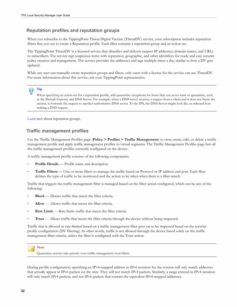
TPS Local Security Manager User Guide
32
Reputation profiles and reputation groupsWhen you subscribe to the TippingPoint Threat Digital Vaccine (ThreatDV) service, your subscription includes reputationfilters that you use to create a Reputation profile. Each filter contains a reputation group and an action set.
The TippingPoint ThreatDV is a licensed service that identifies and delivers suspect IP addresses, domain names, and URLsto subscribers. The service tags suspicious items with reputation, geographic, and other identifiers for ready and easy securitypolicy creation and management. The service provides the addresses and tags multiple times a day, similar to how a DV getsupdated.
While any user can manually create reputation groups and filters, only users with a license for the service can use ThreatDV.For more information about this service, ask your TippingPoint representative.
TipWhen specifying an action set for a reputation profile, add quarantine exceptions for hosts that you never want to quarantine, suchas the Default Gateway and DNS Server. For example, when a DNS server receives a request from a client and it does not know theanswer, it forwards the request to another authoritative DNS server. To the IPS, the DNS Server might look like an infected hostmaking a DNS request.
Learn more about reputation groups.
Traffic management profilesUse the Traffic Management Profiles page (Policy > Profiles > Traffic Management) to view, create, edit, or delete a trafficmanagement profile and apply traffic management profiles to virtual segments. The Traffic Management Profiles page lists allthe traffic management profiles currently configured on the device.
A traffic management profile consists of the following components:
• Profile Details — Profile name and description.
• Traffic Filters — One or more filters to manage the traffic based on Protocol or IP address and port. Each filterdefines the type of traffic to be monitored and the action to be taken when there is a filter match.
Traffic that triggers the traffic management filter is managed based on the filter action configured, which can be any of thefollowing:
• Block — Denies traffic that meets the filter criteria.
• Allow — Allows traffic that meets the filter criteria.
• Rate Limit — Rate limits traffic that meets the filter criteria.
• Trust — Allows traffic that meets the filter criteria through the device without being inspected.
Traffic that is allowed or rate-limited based on a traffic management filter goes on to be inspected based on the securityprofile configuration (DV filtering). In other words, traffic is not allowed through the device based solely on the trafficmanagement filter criteria, unless the filter is configured with the Trust action.
NoteQuarantine actions take priority over traffic management trust filters.
During profile configuration, specifying an IPv4-mapped address in IPv6 notation for the version will only match addressesthat actually appear in IPv6 packets on the wire. They will not match IPv4 packets. Similarly, a range entered in IPv4 notationwill only match IPv4 packets, and not IPv6 packets that contain the equivalent IPv4-mapped addresses.

TPS Local Security Manager User Guide
33
Learn more about managing virtual segments associated with security profiles using the Virtual Segments page.
Sample traffic management profile
You can use traffic management filters to prioritize traffic or implement security policy. For example, you might define thefollowing IP filters for your web servers in a lab that denies access to external users:
• Block traffic if the source is on an external subnet that arrives through port 80 and is destined for the IP address of yourweb server.
• Block traffic if the source is your web server, the source port is 80, and the destination is any external subnet.
You can define multiple traffic management rules in each profile. In general, when you define filters for network segments,more specific filters should come first. For example, a more specific IP filter might block traffic with fully qualified sourceand destination IP addresses and ports. More general ones, like those that apply to subnets, should follow.
The following table lists several examples of traffic management filters:
Sourceaddress
Destinationaddress Protocol Source
portDestination
port Action
any any UDP any 53 Allow
any any UDP any any Block
any any ICMP any any 20 Mbps rate-limit
any 1.2.3.4 TCP any 80 Allow
any any TCP any 80 Block
66.94.234.13 any IP any 80 Block
These filters perform the following actions:
• Block all UDP traffic except DNS requests. DNS requests are inspected for attacks.
• Limit all ICMP traffic to 20 Mbps.
• Block all HTTP traffic except for server 1.2.3.4.
• Block IP fragments coming from IP address 66.94.234.13 on any port going to port 80.
SSL inspection profiles
An SSL inspection profile enables a supported TPS security device to decrypt and inspect inbound encrypted traffic. See thefollowing sections for more information.
Considerations
When deploying SSL inspection, consider these points:
Consideration Description
Inbound IPv4 traffic only The TPS inspects inbound IPv4 traffic, including HTTP and HTTPS traffic.Inbound SSL inspection does not support:
• IPv6 traffic, including IPv4 over IPv6 tunneling
• Outbound IPv4 traffic and IPv6 traffic

TPS Local Security Manager User Guide
34
Consideration Description
Tunneled traffic Supported SSL encapsulations:
• GRE (Generic Routing Encapsulation)*
• IPv4 (IP-in-IP)
• One layer of tunneling only for both GRE and IPv4-in-IPv4. SSL inspectiondoes not include support for GTP or IPv6 encapsulations.
*GRE support includes the mandatory GRE fields. Optional GRE keyconfiguration is also supported but requires the key to be the same value for bothdirections. SSL inspection does not support other optional GRE fields, such asGRE sequence number.
Quarantine hosts and redirecting HTTPtraffic to another site
When configuring an Action Set to quarantine hosts, if you also configure theresponse to redirect traffic to an HTTP server, the device redirects the HTTPtraffic from the quarantined host but does not redirect the HTTPS traffic.
Filter Precedence The TPS processes filters in the following order of precedence:
1. Inspection Bypass Rules
2. Traffic Management Filters
3. RepDV
4. Quarantine
5. Digital Vaccine Filters
When encrypted traffic is routed through the device and SSL inspection isconfigured, the TPS order of precedence applies to the decrypted traffic. TheTPS does not quarantine or apply Digital Vaccine filters to traffic without firstdecrypting the traffic.
If SSL inspection is not configured, the device applies Inspection Bypass, TrafficManagement, RepDV, and quarantine filtering against the encrypted traffic. Thedevice applies Digital Vaccine filters, but they do not match against encryptedpayload.
Non-encrypted traffic when SSL isconfigured
• The TPS device drops non-encrypted traffic flows that match a configuredSSL server tuple (destination port and destination IP address) in the SSLprofile but send cleartext traffic before starting an SSL handshake (as someprotocols allow via STARTTLS).
• The TPS device drops non-encrypted traffic flows that match a configuredSSL server tuple (destination port and destination IP address) in the SSLprofile due to the lack of an SSL handshake.
Traffic Management filters - Trust action The TPS device continues to proxy the SSL session between the client and theserver when HTTPS traffic matches a traffic management filter that is set to Trust(incoming traffic is trusted and not inspected).
Packet trace Packet Trace as an action includes the decrypted traffic.
Traffic capture Traffic capture by tcpdump does not include the decrypted contents.
L2FB/ZPHA The TPS device clears proxied SSL sessions when the device enters IntrinsicHA Layer-2 Fallback or Zero Power High Availability (ZPHA).
Requirements
Make sure your environment meets the following requirements:
• Device support – the following TPS devices support SSL inspection:

TPS Local Security Manager User Guide
35
• TX Series (8200TX and 8400TX)
• 2200T
• Virtual TPS (performance image only, with RDRAND instruction recommended) security devices. For informationabout how to deploy the vTPS virtual appliance for SSL inspection, see the vTPS Deployment Guide.
Note
If you need to configure SSL v3.0 with TLS, always configure all TLS protocols, including TLS v1.0, TLS v1.1, and TLS v1.2.You must enable all SSL protocols between the configured lowest-strength and highest-strength SSL protocols.
Note
SSL inspection is not supported on the TippingPoint 440T TPS security device.
• Licensing – SSL Inspection is licensed separately. To request an SSL Inspection license, contact your sales representative.
• Cipher suite support – The SMS is capable of configuring the following ciphers if your TOS supports them. Older TOSversions may have limited cipher support. Refer to your product release notes for version information. Profiledistribution extended status alerts you to any errors:
• Protocols:
• TLS v1.2, v1.1, and v1.0 (enabled by default)
• SSL v3.0 (disabled by default)
Note
TLS Heartbeat Extension (https://tools.ietf.org/html/rfc6520) is not supported.
• Key exchange algorithms:
• Ephemeral Elliptic Curve Diffie-Hellman with RSA signatures (ECDHE-RSA).
The ECDHE-RSA cipher suite extends SSL inspection capability to Perfect Forward Secrecy (PFS). ECDHE-RSA is enabled by default.
• RSA (enabled by default)
• Authentication algorithm:
• RSA (enabled by default)
• Bulk encryption algorithms:
• AES256 and AES128 (enabled by default)
• 3DES (enabled by default)
• DES (disabled by default)
• Message Authentication Code (MAC) algorithms:
• SHA384, SHA256, and SHA1 (enabled by default)
• VLAN translation – SSL inspection requires that you do not configure VLAN translation on the device.
• Asymmetric Network mode – SSL inspection requires that you do not enable Asymmetric Network mode on the device.

TPS Local Security Manager User Guide
36
License the device
Update your license package to assign an available SSL inspection license to any supported TPS security device. Manage yourlicense package by using the License Manager on the TMC. When you log in to the TMC, the License Manager is under MyAccount > License Manager.
Important
When configuring SSL, make sure that you update both the device certificate and the SSL webserver certificate before they expire. Ifthe certificates expire or become out of sync, the SSL connections might fail.
Procedure
1. In the LSM, select System > Update > System, DV, Licenses.
2. In the License Version panel, click Install.
You are prompted to reboot the device to apply changes. If necessary, save any uncommitted changes to the Runningconfiguration and save them to the Startup configuration before you reboot the device.
3. When the reboot completes, return to the License Version panel and validate that the SSL Inspection feature has aPermit status of Allow.
If the SSL Inspection feature indicates:
• Reboot required – Reboot the device to enable the SSL inspection license.
• Deny – Verify the license package assigns the SSL inspection capability to the device.
Enable SSL inspection
Update the device configuration to enable SSL inspection. To optimize the available resources on the device, do not enableSSL inspection until you are ready to inspect secure traffic.
Before you begin
If necessary, you can disable SSL inspection on the device and configure SSL inspection.
Procedure
1. In the LSM, select Policy > SSL Inspection.
2. In the SSL Inspection Profiles panel, choose Enable SSL Inspection to enable the SSL server to decrypt and inspectclient traffic to your secure servers. If the checkbox is grayed, verify the license package has assigned the SSL Inspectioncapability to the device.
Configure SSL inspection
Configure SSL inspection to specify the SSL sessions you want the TPS device to inspect. The TPS cannot effectively inspectthe encrypted payload of SSL traffic that does not match the SSL inspection profile.
Complete these tasks to configure SSL inspection:
• Import the SSL server certificate and private key
• Add an SSL server

TPS Local Security Manager User Guide
37
• Add an SSL inspection profile
• Assign the SSL inspection profile to a virtual segment
Import the SSL server certificate and private key
SSL inspection requires both the SSL server certificate and its private key from the server of interest. The SMS performsbasic validation on the status of the certificate itself. When using a certificate chain, always import any intermediatecertificates.
Important
When configuring SSL, make sure that you update both the device certificate and the SSL webserver certificate before they expire. Ifthe certificates expire or become out of sync, the SSL connections might fail.
Procedure
1. In the LSM, select Authentication > X.509 Certificates > Device Certificates.
2. In the Device Certificate panel, click Import to import a new SSL certificate.
To update an existing SSL certificate, select the certificate from the list, and then click Import.
3. Enter the certificate name.
(Best Practice) Follow a naming convention so that you can easily and reliably assign the correct certificate to an SSLserver.
4. Click Browse to locate the file.
5. Select the certificate format, either Base64 Encoded Certificate (PEM) or Encrypted Private Key and Certificate(PKCS12).
When selecting:
• PEM format – Always import the private key in a separate file. Be sure to select the Include a Private Keycheckbox, and then browse to the private key file. If the private key is encrypted, enter the appropriate password inthe Password box.
• PKCS12 format – Enter the appropriate password to import the certificate/key pair. When using a certificatechain, always include any intermediate CA certificates in your import file. Only one file can be imported with thecertificate/private key pair and any intermediate CA certificates.
6. Click OK.
The appliance imports the certificate and associated private key, and the certificate is displayed in the Device Certificatestable.
Add an SSL server
Add an SSL server to specify the SSL server configuration to proxy, including the SSL service that is accepted on the SSLdetection port.
Before you begin
For secure HTTP, IMAP, and POP3 traffic, create a separate SSL server to enable DV filtering on the decrypted SSL service.For example, if the web server accepts POP3S traffic on port 2000, add an SSL server with a Detection Port of 2000 and aDecrypted Service of POP3 to enable DV filters for POP3.

TPS Local Security Manager User Guide
38
For other SSL services, such as SMTPS, create an SSL server with a Decrypted Service of Other. The TPS device applies DVfilters to the incoming traffic, but does not apply them to the decrypted SSL service.
To inspect more than one decrypted service on a particular SSL server, define the same server IP for each service you want.For example, you can define a server with IP 1.1.1.1 and port 443 (HTTPS), and another server with IP 1.1.1.1 and port 995(POP3S), and associate them with the same SSL inspection profile.
Procedure
1. In the LSM, select Policy > SSL Inspection > Servers.
2. In the SSL Servers panel, click Add or Edit.
The Edit SSL Server dialog box displays.
3. In the SSL Server Config tab, specify the following settings:
• Name - Enter an SSL server name that corresponds to your Web server name so that you can easily associate itwith your web server.
• Server Certificate: Select the SSL certificate for your web server.
Note
The LSM does not validate the server certificate.
• Server Addresses: Specify the server IPv4 address or CIDR range.
• Decrypted Service: Choose the SSL service that is accepted on the SSL Detection Port to enable filtering for thatparticular service. If the SSL service you want is not listed, choose Other.
• SSL Detection Ports: Specify the port range of the encrypted application traffic. For example, if the web serveraccepts POP3S traffic on port 2000, specify 2000.
• Rekey Interval: Specify the interval, in seconds, that your web server forces renegotiation of the shared SSL key. Ifyour web server does not offer renegotiation of the shared SSL key, leave this blank.
• Enable logging: Select this option to enable the TPS to write log information about SSL inspection to theexternal user disk (CFast or SSD). This option collects detailed logging information and should only be enabled fortroubleshooting purposes. For example, enable this option if, after you set up SSL inspection, the TPS does not seeSSL session activity. By default, this option is disabled. To learn more about viewing log information, see Basictroubleshooting.
• Allow compression: Select this option to allow the SSL compression algorithm to be negotiated during the SSLhandshake. If your web server does not offer negotiation of SSL compression, disable this option. By default, thisoption is disabled. If you select this option, and your web server does not offer SSL compression, this setting isignored.
• Send TCP reset to server for blocked sessions: Select this option to always send a TCP reset to the serverwhenever the TPS blocks an SSL session. This option overrides the TCP reset action set, if enabled, on a DV filter.
Enable this option so that protected servers can release network resources quickly if flows are blocked. When thisoption is disabled, the TCP reset action, if enabled on a DV filter, still applies.
4. In the Cipher Suites tab, choose the protocols and algorithms that are supported by your web server.
The Cipher Suite list automatically updates based on your selections. Deselect any cipher suites that you do not want.
5. Click OK. You are now ready to add the SSL server to an SSL inspection profile.

TPS Local Security Manager User Guide
39
Add an SSL inspection profile
Add an SSL profile to specify each SSL server that you want to protect, and any SSL client exceptions.
Important
Always configure the SSL inspection profile for the virtual segment that receives the initial SSL client request to your server.
Procedure
1. Select Policy > SSL Inspection > Profiles.
2. In the SSL Inspection panel, click Add or Edit.
The SSL Profile Editor opens.
3. Enter the SSL profile name, for example, myapp_SSLprofile.
4. Under Server Policies, click Add.
The Add SSL Server Policy dialog box opens.
5. Specify the following settings:
• Enable: Deselect the checkbox to exclude this SSL Server Policy from the SSL inspection profile. By default, thisoption is selected.
• Name: Specify a policy name, for example, that corresponds to the SSL server configuration.
• SSL Server: Choose a server to include in SSL inspection.
• Source Address Exception: Specify any client IP addresses to exclude from SSL inspection.
6. Click OK.
You are now ready to assign the SSL inspection profile to a virtual segment.
Assign the SSL inspection profile to a virtual segment
Always assign the SSL profile to the virtual segment that receives the initial SSL client request to your server.
Important
You do not need to distribute an SSL inspection profile to the virtual segment that receives the SSL server response. The SSLinspection policy enables the device to proxy (and decrypt) the SSL session between both the SSL client and the device, and betweenthe SSL server and the device.
If you do not want the device to inspect the decrypted payload in the SSL server response, distribute an inspection profile tothe outbound virtual segment that disables the Application filters and the Security filters. To maximize available inspectionresources on the device, disable all filter categories and filter overrides in the inspection profile for the outbound virtualsegment.
Procedure
1. In the LSM, click Network > Virtual Segments.
2. Click Add or Insert to create a new virtual segment, or click Edit to edit an existing virtual segment. Virtual segmentsthat are created by the system can have their profiles modified but are otherwise read-only.

TPS Local Security Manager User Guide
40
• Clicking Add adds the new virtual segment after all the other user-created virtual segments.
• Clicking Insert inserts the new virtual segment just before the currently selected virtual segment.
• All system-created virtual segments always appear at the end of the list.
3. In the Add Virtual Segment dialog or Edit Virtual Segment dialog, specify the following:
• Name – (Required) Name used to identify the virtual segment. Each virtual segment must have a unique name.
• Description – An optional parameter to provide more detailed information about the virtual segment.
• IPS Profile – Security profile that you want to apply to the virtual segment. A virtual segment can have only oneIPS profile applied to it.
• Reputation Profile – Reputation profile that you want to apply to the virtual segment. A virtual segment can haveonly one Reputation profile applied to it.
• Traffic Management Profile – Traffic Management profile that you want to apply to the virtual segment. Avirtual segment can have only one Traffic Management profile applied to it.
• SSL Profile – SSL profile that you want to apply to the virtual segment. A virtual segment can have only one SSLprofile applied to it.
• Physical Segments – Physical segment associated with the virtual segment. All physical segments are directional.
• Traffic Criteria – (Required) Specify any one or all of the following: VLAN ID, Source IP, and Destination IP. Forexample, omit VLAN ID and specify Destination IP. When specifying a VLAN ID, specify a value between 1 and4094 in which the segment is included. There can be no duplicate VLAN IDs or overlapping VLAN ranges. All4094 VLAN IDs can be used per virtual segment (a VLAN range of 1–100 counts as 100 IDs). At least one trafficcriteria (VLAN ID, source IP address, or destination IP address) must be defined for each virtual segment.
• Source IP Address – Source CIDR associated with the virtual segment. Addresses must be valid IPv4 format. Thehost portion of address/mask must be 0 (zero). No more than 250 addresses may be specified.
• Destination IP Address – Destination CIDR associated with the virtual segment. Addresses must be valid IPv4format. The host portion of address/mask must be 0 (zero). No more than 250 addresses may be specified.
4. Click OK.
Note
Virtual segments must be created with a physically available segment. If creating a virtual segment generates a UDM warning inthe system log, ensure you have associated the virtual segment with a valid physical segment.
5. If you are ready to commit your pending changes to the Running configuration, in the Configuration menu, clickCommit pending changes.
Troubleshoot SSL inspection
If SSL clients cannot reach the server, check Traffic Management and Reputation filters to verify the sessions of interest arenot blocked. Traffic Management and Reputation filters are applied before SSL inspection.
Basic troubleshooting
If SSL clients are reaching your server but the TPS device is not inspecting some or all of the encrypted sessions of interest,check the following items:
• System log – Determine whether the TPS device is bypassing SSL sessions.

TPS Local Security Manager User Guide
41
• SSL server configuration – Verify the SSL server IP and ports.
• SSL inspection profile – Confirm any SSL inspection policies do not include a source IP exception that would bypassSSL inspection.
• Virtual segment – consider the following:
• If the virtual segment designates a segment, confirm that it is the correct segment. For example, confirm thatinterface 1A receives the SSL client request to your SSL server.
• If the virtual segment defines VLANs, confirm that the VLANs are correct for your SSL server.
• If the virtual segment defines source IP addresses, confirm that the SSL client requests correspond to those IPaddresses.
• If the virtual segment defines destination IP addresses, confirm that your SSL server corresponds to one of thoseaddresses.
To verify Do this
The TPS is not bypassing SSL sessions On the device, check the System log for an entry similar to thefollowing: SSL Inspection reached Critical thresholdof Max Concurrent Connections. Action: Allow butbypass Inspection
If the number of concurrent SSL sessions exceeds themaximum threshold as specified by the entry in the Systemlog, the TPS device does not inspect them. If necessary,reconfigure SSL inspection to reduce the number ofconcurrent SSL connections. For information aboutconfiguring SSL inspection to block SSL sessions that exceedthe maximum threshold, contact customer support.
SSL inspection license is installed and valid Verify the license package.
SSL inspection is enabled Enable SSL inspection.
The correct certificate and key are installed Import the SSL server certificate and private key.
The SSL server matches the correct IP address and port Edit the SSL server.
The profile is applied to the correct virtual segments Distribute the inspection profile.
The virtual segment includes the desired SSL server IPaddresses and ports
Verify the SSL clients are reaching the SSL server.
Advanced troubleshooting
If the basic troubleshooting does not resolve your issue, troubleshoot the TPS device.
Procedure
1. Verify the list of inspected SSL sessions. In the LSM, click Monitor > Sessions > SSL Sessions or, from the deviceCLI run the show tse ssl-inspection command.
Entries are only present for the life of the session. If necessary, use the debug np ssl-clear command to forciblyclose the SSL sessions. If an entry does not exist, proceed to the next step.
2. Run the debug np stats show npSslInspStats command to check the connection counters. If they are all zero,then it is likely that you have a configuration issue. If there are refused connections, it is also a configuration issue, butthere are likely incompatible ciphers or the connection is trying to use compression when the profile does not support it.Learn more.

TPS Local Security Manager User Guide
42
3. Run the debug np stats show npSslInspProtocolStats command and consider these points:
• Non-zero entries in the clientCipherOther counter – Indicate a possibly unsupported cipher. Use the othererror counters to narrow the source of the problem to at least the server or the client.
• Server connection failures – Indicate a possibly unsupported cipher, but with the added chance that the servermight be asking for a client certificate, which the proxy does not support.
4. Run the debug np stats show npTcpProxyStats command to confirm whether the profile and server areconfigured to correctly match traffic. If the results are all zero, then there is no matching traffic to inspect. If there is anyTCP traffic that matches a profile, the results are non-zero.
Inspection bypass rules
You can configure inspection bypass rules with TippingPoint TPS devices. Traffic that matches inspection bypass rules isdirected through the IPS without inspection. You can apply these rules to traffic according to source or destination IPaddress, port, or CIDR (Classless Inter-Domain Routing). You can also apply the rules to traffic moving through specificports.
Define up to 32 inspection bypass rules on a TippingPoint TPS device. Rule configurations that bypass traffic or VLANranges require additional hardware resources. For example, a single inspection bypass rule for VLAN traffic can result inmultiple port-VLAN rule combinations.
Inspection bypass rule (for a single port) Resulting number of port-VLAN rulecombinations
IPv4/IPv6 traffic on TCP 1556 with untagged traffic or a particularVLAN ID
1
IPv4/IPv6 traffic on TCP 1556 with VLAN 10 – 100 91
Each TPS supports a maximum number of port-VLAN rule combinations. If the number of configured port-VLAN rulecombinations exceeds the maximum threshold for the device, you cannot commit the changes.
For aMaximum (approximate) number ofport-VLAN rule combinations when
bypassing IPv4 traffic
Maximum (approximate) number of port-VLAN rule combinations when bypassing
IPv6 traffic
440T device 256 128
2200T device 2560 1280
8200TX/8400TXdevice
512 512
From the list of inspection bypass rules, you can reset the Packet Hit Count for a particular rule by selecting the rule andclicking Reset Counts. To refresh the entire list, click Refresh at the top of the page.
Add or edit an inspection bypass rule
Add or edit an inspection bypass rule to enable or disable the rule and to specify the traffic that you do not want to inspect.
You can also define Inspection bypass rules with the inspection-bypass context in the CLI. Refer to the Threat ProtectionSystem Command Line Interface Reference for more information.

TPS Local Security Manager User Guide
43
Procedure
1. Select Policy > Inspection Bypass.
2. In the Inspection Bypass Rules panel, click Add or Edit and specify the following settings.
• Name – Specify the name of the inspection bypass rule.
• Enabled – Select this option to enable the inspection bypass rule. This option is enabled by default.
• Ethernet Type – Choose an option to specify the EtherType or choose Custom to specify the hexadecimal valueof the EtherType to bypass. When specifying a hexadecimal value, prepend the value with 0x, for example,0x0806 for ARP. By default, IP is selected.
Note
You can see a full list of EtherType values at the Internet Assigned Numbers Authority website.
• IP Protocol – Choose an option to specify the IP protocol or choose Custom to specify the IP protocol value tobypass.
Note
You can see a full list of IP protocol values at the Internet Assigned Numbers Authority website.
• Source address and ports – Specify the source IP address and port range to bypass.
• Destination address – Specify the destination IP address and port range to bypass.
• Action – Specify which action the rule applies to the traffic.
• Bypass (default) – Bypasses the traffic.
• Block – Blocks the traffic.
• Redirect – Redirects the traffic. An Action Target Port field (required) is displayed for you to specify whichsegment port the traffic gets redirected to. This option is unselectable if no target port is available.
• Ingress mirror – Mirrors (copies) the traffic that enters the port to another segment port before the trafficgets inspected. An Action Target Port field (required) is displayed for you to specify which segment port thetraffic gets mirrored to. Four mirror-to-port (MTP) configurations are supported. This option is unselectableif no target port is available.
• Egress mirror – Mirrors (copies) the inspected traffic that exits the port to another segment port. An ActionTarget Port field (required) is displayed for you to specify which segment port the traffic gets mirrored to.Four MTP configurations are supported. The port-assigned VLAN is recorded inside the captured packet.This option is unselectable if no target port is available.
• VLAN – Choose an option to specify the VLAN traffic to bypass.
• ID or Range – Use this option to specify the tagged traffic you do not want to inspect. For example, specify12-15 to not inspect tagged traffic on VLANs 12 to 15.
• None – Use this option to bypass all untagged traffic.
• Any – Use this option to bypass any tagged or untagged traffic. This option is selected by default.
• Segments Bypass a port by choosing the incoming port from the list and clicking Add.

TPS Local Security Manager User Guide
44
NoteInspection bypass applies to incoming traffic only.
3. Click OK.
Inspection profile settingsSelect Policy > Settings to configure the following:
Setting Description
Connection Table Specifies the global timeout interval for TCP traffic or non-TCP traffic on theconnection table.
For blocked streams in the connection table, this value determines the time intervalthat elapses before the blocked connection is cleared from the connection table.Before the timeout occurs, the device blocks any incoming packets for that stream.After the connection is cleared (the timeout interval expires), the incoming connectionis allowed until traffic matches another blocking filter.
Trust Streams Specifies the global timeout interval for trusted streams.
This value determines the time interval that elapses before the trusted stream isflushed.
Quarantined Addresses This value determines the time interval that elapses before the quarantined host canbe released. After the quarantined host is released (the timeout interval expires),quarantined addresses can be automatically released, if you select that option.
HTTP Response Processing Specifies inspection of encoded HTTP responses.
• Accelerated inspection of encoded HTTP responses — Uses hardwareacceleration to detect and decode encoded HTTP responses.
• Inspect encoded HTTP responses — Enables strict detection and decoding ofencoded HTTP responses.
• Ignore encoded HTTP responses — The device does not detect or decodeencoded HTTP responses.
Enable decoding of URL encodings and Numeric Character References (NCR).This option is enabled by default.
GZIP Decompression Decompresses files that have been compressed in the gzip file format.
Asymmetric Network Specifies whether the device is configured for an asymmetric network. When youenable asymmetric configuration, the device does not see both sides of a TCPconnection. This option is disabled by default.
NoteYou must disable Asymmetric Network mode for DDoS filters and SSLinspection.
DNS Reputation Enables the device to respond with NXDOMAIN (name does not exist) to clients thatmake DNS requests for blocked hosts.
HTTP Mode Enables all TCP ports to be treated as HTTP ports for inspection purposes. If a flowdoes not have HTTP traffic, HTTP processing stops so that optimum performance ismaintained.

TPS Local Security Manager User Guide
45
Setting Description
IDS Mode When you enable IDS mode, the device configuration becomes adjusted so that thedevice operates in a manner suitable for Intrusion Detection System (IDS) scenariosand filter configurations.
• Performance protection is disabled.
• Adaptive Filtering is set to Manual.
• Filters currently set to Block are not switched to Permit, and Block filters can stillbe set.
When you change IDS Mode settings, reboot the device for the change to take effect.
ImportantChanging IDS Mode does not change Performance Protection mode. For bestresults, when enabling IDS Mode, go to the System > Settings > LogConfiguration > Performance Protection page and change PerformanceProtection to Always log Alert and Block events mode.
Reset Security Profile Removes all user-created security policy configuration changes from the device,including user-created profiles, user-created virtual segments, filter configurations insecurity profiles, and action sets.
Object configurationYou can monitor and configure the settings for objects used by the device.
Action sets
Note
This is an Instant-Commit feature. Changes take effect immediately.
Action sets determine what the device does when a packet matches a rule or triggers a filter. An action set can contain morethan one action, and can contain more than one type of action. The types of action that determine where a packet is sent afterit is inspected include the following:
• A permit action enables a packet to reach its intended destination.
• A block action discards a packet. A block action can also be configured to quarantine the host and/or perform a TCPreset.
• A rate limit action enables you to define the maximum bandwidth available for the traffic stream.
• A trust action enables the designated traffic to bypass all inspection; the traffic is transmitted immediately. Trust haslower latency than Permit, and using it can reduce load on the CPU and processors.
Action Name Description
Recommended The default action set, as determined by the filter’s category settings. When you assignthis action set to a filter, the filter uses the recommended action setting for the defaultcategory settings. The recommended action set can enable different configurations forfilters within the same category. Under a recommended category setting, some filters aredisabled while others are enabled; some might have permit actions assigned while othersare set to block.

TPS Local Security Manager User Guide
46
Action Name Description
Block (+TCP Reset) Blocks a packet from being transferred to the network. You can use the TCP Resetoption for resetting blocked TCP flows.
Block + Notify (+TCP Reset) Blocks a packet from being transferred. Notifies all selected contacts of the blockedpacket. You can use the TCP Reset option for resetting blocked TCP flows.When you create an action set with Block + Notify + TCP Reset Destination, when aReputation filter is hit, the TCP Reset to the Destination IP does not work properly. Toresolve this problem, do not use the 'tcp reset' feature or only use 'tcp reset both' whenthe trigger reason is Reputation.
Block + Notify + Trace (+TCP Reset) Blocks a packet from being transferred. Notifies all selected contacts of the blockedpacket. Logs all information about the packet according to the packet trace settings. Youcan use the TCP Reset option for resetting blocked TCP flows.
Permit + Notify Permits a packet and notifies all selected contacts of the packet.
Permit + Notify + Trace Permits a packet. Notifies all selected contacts of the packet, and logs all informationabout the packet according to the packet trace settings.
Trust Not configured on the device by default; you must create a Trust action set for this actionto be displayed on the table. Enables trusted traffic to pass without inspection. Lowerlatency than Permit. Cannot be used with DDoS or IP Reputation filters.
Add or edit an action set
Procedure
1. Select Policy > Objects > Action Sets.
2. Click Add to create a new action set or Edit to change an existing one.
3. Under the General tab:
a. Enter the name of the action set.
b. (Optional) Select the action from the Action list.
c. Select whether the option to reset a TCP connection is enabled. With TCP Reset enabled, the system resets theTCP connection for the source or destination IP when the Block action executes. You can configure this option onBlock action sets.
d. (Optional) Select Packet Trace. Packet Trace enables you to capture all or part of a suspicious packet for analysis.You can set the packet trace priority and packet trace verbosity for action sets.
• Priority sets the relative importance of the information captured. Low priority items are discarded beforemedium priority items if there is a resource shortage.
• Verbosity determines how much of a suspicious packet is logged for analysis. Full verbosity records the wholepacket. Partial verbosity enables you to choose how many bytes of the packet (from 64 to 25,618 bytes) thepacket trace log records.
4. Under the Notification Contacts tab, configure notification contacts (either human or machine) that get sent messages inresponse to a traffic-related event. You can configure any of the following notification contacts to be notified when theaction is triggered:
• Remote System Log – Sends messages to a syslog server on your network. This is a default contact available in allaction sets.

TPS Local Security Manager User Guide
47
• Management Console – Sends messages to the LSM device management application. This default contact isavailable in all action sets. If you select this contact, messages are sent to the Alert or IPS Block Log in the LSM,depending on whether a permit or block action has executed.
5. Under the Quarantine tab, assign a quarantine action set to a filter. You can select the following quarantine options forthe action set:
• (Optional) Select Quarantine hosts that trigger this action to quarantine the IP addresses that trigger thisoption.
• Select Quarantine hosts after first hit to quarantine the host after the first hit.
• Select Quarantine host after to activate the quarantine after the specified number of hits (2 – 10,000) duringthe specified number of minutes (1 – 60).
• Select Block non-HTTP traffic sent from quarantined hosts – To block the non-HTTP requests.
• Select an action from the Response to HTTP traffic sent from quarantined hosts list:
• Displaying quarantine info – Select Event that triggered the quarantine action to display the events thattriggered the quarantine action and select Text below to insert custom text.
• Blocking it – To block the response to the HTTP traffic.
• Redirecting to the following site – To redirect the HTTP requests from the quarantined host to a website.
6. Under the Quarantine Exceptions tab, you can select the following quarantine exceptions for the action set if youenabled the Quarantine hosts that trigger this action option in the preceding step:
• Only quarantine these hosts – To quarantine specified hosts, enter the IP address/mask and click Add.
• Do not quarantine these hosts – To exclude the specified hosts from quarantine, enter the IP address/mask andclick Add.
• Allow quarantined hosts to access these addresses – To allow the quarantined hosts to access the specifiedaddresses, enter the IP address/mask and click Add.
7. Click OK or OK/Continue to add another action set.
Notification contactsConfigure notification contacts to send messages to a recipient (either human or machine) in response to a traffic-relatedevent that occurs on the device. The traffic-related event can be the result of triggering an IPS filter configured with an actionset that specifies a notification contact. A notification contact can be any of the following:
• Remote System Log — Sends messages to a syslog server on your network. The syslog server uses the numbers youspecify for the Alert Facility and the Block Facility to identify the message source. After you configure this contact,verify that your device can reach the remote system log server on your network. If the remote system log server is on adifferent subnet than the management port, you might need to configure the routing. Learn more. This is a defaultcontact available in all IPS action sets.
CAUTION!Remote syslog, in adherence to RFC 3164, sends clear text log messages using the UDP protocol with no additional securityprotections. Use remote syslog only on a secure, trusted network to prevent syslog messages from being intercepted, altered, orspoofed by a third party.
• Management Console — Sends messages to the LSM. This default contact is available in all action sets. If you selectthis contact, messages are sent to the Alert or IPS Block Log in the LSM, depending on whether a permit or block

TPS Local Security Manager User Guide
48
action has executed. This notification contact does not require any configuration, although you can change the defaultname and aggregation period.
• Email or SNMP — Sends messages to the email address or specified SNMP. All email or SNMP contacts must beadded from the Notification Contacts page. If the default email server is not configured on the device, you are promptedto configure it before adding a contact. After you configure this option, verify that the email server is reachable from thedevice, that mail relaying is enabled, and that you use an acceptable account/domain.
Note
SNMP notification contacts require SNMPv2, and do not work when SNMPv2 is disabled. Before creating an Email ornotification contact, you must configure Email and SMTP server settings on the device from the System > Email page. Learnmore.
After configuring notification contacts, you can select them for IPS filter events when you create or edit the action setassigned to the filter. You cannot delete the default Remote System Log and Management Console contacts. You cannotdelete a Notification Contact if it is currently configured in another Action Set.
Note
Changes to notification settings take effect immediately.
Alert aggregation and the aggregation period
The device uses alert aggregation to prevent system performance problems resulting from an excessive number ofnotification requests. Because a single packet can trigger an alert, attacks with large numbers of packets could potentiallyflood the alert mechanism used to send out notifications. Use alert aggregation to receive alert notifications at intervals toprevent this flooding. For example, if you set the aggregation interval to 5 minutes, the system sends an alert at the first IPSfilter trigger, collects subsequent alerts and sends them out every five minutes.
On the device, the aggregation period that you configure when you create a notification contact controls alert aggregation. Allnotification contacts require this setting.
CAUTION!
Short aggregation periods can significantly affect system performance. The shorter the aggregation period, the higher the systemload. In the event of a flood attack, a short aggregation period can lead to system performance problems.
In addition to the user-configured aggregation period, the system also provides alert aggregation services to protect thesystem from over-active filters that can lower performance.
For email contacts, the aggregation period works in conjunction with the email threshold setting configured for the email server.Learn more.
Reputation groups
You can create groups of IP addresses and DNS names, known as reputation groups, as a part of IPS profiles. Use thisfeature to create groups of IPv4, IPv6, and DNS addresses and define an action set to apply to all of those addresses.
Any item that you add to a reputation group, such as an IP address or DNS name, gets added to the device’s reputationdatabase. Incoming traffic is checked against the database, and the appropriate reputation filters are then applied. While theaddress or name is being looked up, you can choose to have packets from a suspect address dropped or permitted.

TPS Local Security Manager User Guide
49
Note
Reputation filter hits in the logs appear to report traffic protocol as ip instead of ip6. These hits are actually showing the matchedsignature’s protocolType instead of the traffic protocolType. Traffic protocols can be confirmed by checking the source anddestination addresses.
The TippingPoint SMS offers additional reputation features; learn more in the Tipping Point Security Management System UserGuide.
Services
Configure additional ports associated with specific services and protocols using the Services page. The additional portsexpand the range of traffic scanned by the device. During the inspection process, the device first scans traffic against thestandard ports for listed services, and then scans traffic against the list of additional ports you configure. You can configureup to 16 additional ports for each service other than HTTP. For HTTP, you can configure only eight additional ports.
Manage authenticationUse the LSM Authentication pages to accomplish the following tasks:
• Create and manage user accounts
• Set user account preferences
• Manage device certificates
• Manage CA certificates
• Log in administratively to the management console
• Configure fine-grained access to the functional areas of the management console using locally defined users, usergroups, roles, or an established LDAP, RADIUS, or TACACS+ server.
Authentication serversThe TPS device supports three types of back-end servers for remote authentication:
• RADIUS Server
• TACACS+ Server
• LDAP Server
You can configure and prioritize (in the order in which they are provisioned) up to two RADIUS or TACACS+ groups. Anyattempt to configure more than two groups returns an error. You can add, edit, and prioritize up to six individual servers in agroup.
When deciding between RADIUS and TACACS+ remote authentication, consider the following:
• RADIUS authenticates over UDP, which requires it to account for transmission errors, such as packet loss. Onlypasswords are encrypted between a RADIUS client and server.
• TACACS+ authenticates over TCP. Because TCP is a connection-oriented protocol, TACACS+ does not requiretransmission control the way RADIUS does. While RADIUS encrypts only passwords, TACACS+ uses MD5 encryptionon all communication and is consequently less vulnerable to attacks.

TPS Local Security Manager User Guide
50
Note
By default, LDAP, RADIUS, and TACACS+ servers send traffic over the management port.
LDAP groups
Use the LDAP Groups panel to configure up to six v2 or v3 LDAP servers for administrative login authentication andnetwork user authentication.
The TPS device checks the accessibility of each server when it is created or modified. Inaccessible servers get recheckedperiodically by the device (approximately once every five minutes). The system log reflects whether the state of the server haschanged. To prevent login delays, the device contacts only accessible servers in order of priority. If all the servers areinaccessible, the device contacts the highest priority server.
The LDAP Server Groups page displays details of the LDAP server groups configured.
Note
The name you provide for each group cannot be changed. To give a group a new name, you must delete the group and re-create itwith the new name.
The Bind Distinguished Name (Bind DN) identifies the user on the external LDAP server who has permission to search theLDAP directory. One or more attribute=value pairs, separated by commas, make up the Bind DN. Configure the followingfields for the Bind DN:
• Bind DN – Provides the user permitted to search the LDAP directory.
• Bind Password – Provides the password for the user permitted to search the LDAP directory.
• Base DN for Tree Search – Indicates the starting point for searches on the LDAP directory.
The Transport Layer Security (TLS) provides options for encrypting communication to the LDAP server. Configure TOSusing the following fields:
• TLS Encryption Enables TLS Encryption.
• Start TLS over LDAP enables TLS security to use both secure and non-secure requests against the LDAP server in asingle connection. For example, modifications to the LDAP server are secure, but reading parts of the directory that areopen for unauthenticated viewing do not use secure requests.
• Valid Server X.509 Certificate enables the use of an X.509 certificate for secure authentication. Select Authentication> X.509 Certificates to import the CA certificate required to validate the server's certificate.
RADIUS groups
A RADIUS group is a group of RADIUS servers with a common configuration, including:
• Device user group
• Authentication protocol and the number of server retries
When the authentication protocol is PEAP/EAP-MSCHAPv2, be sure to also import the CA root certificate. The RADIUSgroup authenticates against the available CA root certificates on the device.

TPS Local Security Manager User Guide
51
Add or edit RADIUS group
Procedure
1. Select Authentication > Authentication Servers > RADIUS Server Groups.
2. Click Add to create a new RADIUS group or Edit to change an existing one.
3. In the Add RADIUS Server Group dialog, enter a name up to 64 characters in length.
Note
The name you provide for each group cannot be changed. To give a group a new name, you must delete the group and re-create it with the new name.
4. (Optional) Select the Default User Group as None or administrator/operator/superuser or click the ellipses (...), whichopens the Add Default User Group dialog, to create a new user group. This is the group a RADIUS user will beassigned if the response contains no Filter-ID attribute.
5. Select the Authentication Protocol from the list:
• PAP
• MD5 (EAP-MD5-Challenge, RFC 3748)
• PEAP/EAP-MSCHAPv2
Note
To use the PEAP/EAP-MSCHAPv2 protocol, you must first import the CA root certificate for the RADIUS server orservers in the group. Users interested in TLS can alternatively use PEAP/EAP-MSCHAPv2 authentication.
6. Specify the number of Server Retries between 0 and 3. The default value is 1.
7. In the RADIUS Servers panel, add a server to the group by specifying the following:
Setting Description
Server IP Address of the RADIUS server.
Port Port on the RADIUS server that listens for authentication requests. The default port is1812.
Timeout Timeout, between 1 and 10 seconds, for communication with the RADIUS server.Default is 2 seconds.
NAS ID (Optional) Value of RADIUS attribute 32, NAS-Identifier. The attribute contains a stringidentifying the NAS (Network Access Server) used in the RADIUS Access-Requestpacket.
Password Case-sensitive string used to encrypt and sign packets between RADIUS clients andthe RADIUS server, set in the RADIUS client configuration file. Maximum is 64characters.
8. Click Add and then OK or OK/Continue to enter another contact.
9. Reorder the RADIUS servers to specify the order in which the IPS communicates with the authentication servers in thegroup. Select the server you want to reorder and click Move Up or Move Down.

TPS Local Security Manager User Guide
52
TACACS+ groups
A TACACS+ group is a group of TACACS+ servers with a common configuration, including:
• Device user group
• Authentication protocol and the number of server retries
Add or edit TACACS+ group
Procedure
1. Select Authentication > Authentication Servers > TACACS+ Server Groups.
2. Click Add to create a new TACACS+ group or Edit to change an existing one.
3. In the dialog, enter a name up to 64 characters in length.
Note
The name you provide for each group cannot be changed. To give a group a new name, you must delete the group and re-create it with the new name.
4. Select the Default User Group as administrator/operator/superuser (operator is the default) or click the ellipses (...),which opens the Add Default User Group dialog, to create a new user group. This is the group a TACACS+ user will beassigned if the response contains no Filter-ID attribute.
5. Select the Authentication Protocol from the list:
• ASCII
• PAP
• CHAP
6. Specify the number of Server Retries between 0 and 3. The default value is 1.
7. In the TACACS+ Servers panel, click Add to add a server to the group, or click Edit to edit a server already in thegroup. You can add up to six servers in a group. In the dialog that opens, specify the following:
Setting Description
IP Address/Hostname Specify the remote TACACS+ server by one of the following:
• IPv4 address
• IPv6 address
• hostname
• hostname+domain name
Port Port on the TACACS+ server that listens for authentication requests. The default port is49.
Secret / Confirm Case-sensitive string used to encrypt and sign packets between TACACS+ clients andthe TACACS+ server, set in the TACACS+ client configuration file. Minimum of onecharacter is required. Maximum is 64 characters.
Timeout Timeout, between 1 and 15 seconds, for communication with the TACACS+ server.Default is 15 seconds.

TPS Local Security Manager User Guide
53
Setting Description
Test Configuration (Optional) Specify a name and password for testing access to the TACACS+ server,and click Test. A popup message reveals one of two possible results:
• Successfully connected to remote TACACS+ Server.
• Failed to connect to remote TACACS+ Server.
NoteTwo configured servers cannot have the same IP address or hostname. If you attempt to configure a server that duplicatesthese properties, an error message indicates which server you are duplicating.
8. Reorder the TACACS+ servers to specify the order in which the TPS communicates with the authentication servers inthe group. Select the server you want to reorder and click Move Up or Move Down.
Authentication settingsYou can configure global authentication settings that apply to local users and groups created on the device. The globalauthentication settings include options for:
• Password Settings
• Login Settings
• Login Group
Configure authentication settings
Procedure
1. Select Authentication > Authentication Settings.
2. In the Password Settings panel, configure the following settings:
• Password Security Level – Specifies the level of security required when users create a user name and password. Thedefault value is Medium. Options include:
• None – User names cannot contain spaces. The maximum password length is 32 characters.
• Low – The same user name and password requirements as the None setting, plus the following additionalrequirements:
• User names must be at least six characters in length
• A new password must be different than the current password, and passwords must be at least eightcharacters in length
• Medium – The same user name and password requirements as the Low setting, plus the following additionalpassword complexity requirements:
• Contains at least two alphabetic characters
• Contains at least one numeric character
• Contains at least one non-alphanumeric character (examples include ! ? $ * #). Do not use spaces inthe password.

TPS Local Security Manager User Guide
54
• High – The same user name and password requirements as the Medium setting, but passwords must be atleast 15 characters and meet the following additional password complexity requirements:
• Contains at least one uppercase character
• Contains at least one lowercase character
• At least half the characters cannot occupy the same positions as the current password.
• Password Expiry Time – Specifies the length of time that the password is valid. Default value: 30 days
• Password Expiry Action – Specifies the action a user must take if a password expires. Default value: Force user tochange password
3. In the Login Settings panel, configure the following settings:
• Maximum Login Attempts – Specifies the number of times a user can attempt to log in. Default value: 4
• Failed Login Action – Specifies the action to take if the Maximum Login Attempts is reached. Default value:Lockout account or IP address
• Lockout Time – Specifies the length of time to lock out a user if the Failed Login Action includes a user lockout.Default value: 2 minutes
4. Specify the number of minutes that the LSM and CLI can remain idle before timing out.
The default is 180 minutes (3 hours) for both interfaces.
5. In the Login Group panel, configure the following settings:
• Administrative Authentication – Specifies the LDAP, RADIUS, or TACACS+ group to be used for Administrativelogin to the LSM. The local database of users is always enabled by default.
Device certificates
View information about certificates that have been imported to the device using the Device Certificates table. The status of acertificate can be one of the following states:
• Valid
• Not yet valid – The current date occurs before the certificate “valid from” date.
• Expired – The current date occurs after the certificate “expires on” date.
• Self-signed – Warning that the certificate is self-signed.
• Revoked – CRL has revoked the certificate.
• Invalid CA – Certificate CA is invalid.
• Not verified – Certificate status could not be determined; this results when the CA certificate chain is not complete, or isnot marked Trusted.
Add or edit a device certificate
To commit changes to the TPS, you must import both the SSL certificate and its private key from the server of interest. TheIPS does not attempt to validate the status of a device certificate.
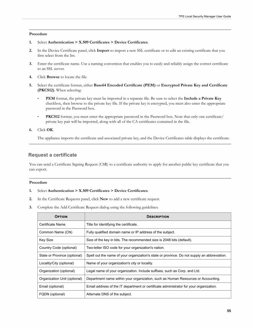
TPS Local Security Manager User Guide
55
Procedure
1. Select Authentication > X.509 Certificates > Device Certificates.
2. In the Device Certificate panel, click Import to import a new SSL certificate or to edit an existing certificate that youfirst select from the list.
3. Enter the certificate name. Use a naming convention that enables you to easily and reliably assign the correct certificateto an SSL server.
4. Click Browse to locate the file.
5. Select the certificate format, either Base64 Encoded Certificate (PEM) or Encrypted Private Key and Certificate(PKCS12). When selecting:
• PEM format, the private key must be imported in a separate file. Be sure to select the Include a Private Keycheckbox, then browse to the private key file. If the private key is encrypted, you must also enter the appropriatepassword in the Password box.
• PKCS12 format, you must enter the appropriate password in the Password box. Note that only one certificate/private key pair will be imported, along with all of the CA certificates contained in the file.
6. Click OK.
The appliance imports the certificate and associated private key, and the Device Certificates table displays the certificate.
Request a certificate
You can send a Certificate Signing Request (CSR) to a certificate authority to apply for another public key certificate that youcan export.
Procedure
1. Select Authentication > X.509 Certificates > Device Certificates.
2. In the Certificate Requests panel, click New to add a new certificate request.
3. Complete the Add Certificate Request dialog using the following guidelines.
Option Description
Certificate Name Title for identifying the certificate.
Common Name (CN) Fully qualified domain name or IP address of the subject.
Key Size Size of the key in bits. The recommended size is 2048 bits (default).
Country Code (optional) Two-letter ISO code for your organization's nation.
State or Province (optional) Spell out the name of your organization's state or province. Do not supply an abbreviation.
Locality/City (optional) Name of your organization's city or locality.
Organization (optional) Legal name of your organization. Include suffixes, such as Corp. and Ltd.
Organization Unit (optional) Department name within your organization, such as Human Resources or Accounting.
Email (optional) Email address of the IT department or certificate administrator for your organization.
FQDN (optional) Alternate DNS of the subject.

TPS Local Security Manager User Guide
56
Option Description
User FQDN (optional) Alternate email of the subject.
Click OK to view the request in the Certificate Requests table.
4. Select the CSR and click Export to generate the certificate request.
CA certificatesYour device attempts to validate the status of any certificate presented during authentication (such as from an LDAP server).In order to validate a given certificate, you must import a sufficient chain of CA certificates. To import CA certificates, usethe Authentication > X.509 Certificates > CA Certificates page and add the CA to the Certificate Authority list.
The CA Certificates table contains the following information:
CA Name Name you specified for the certificate.
Common Name Name assigned to the CA certificate by the creator. It can be set to any value.
Expires On Certificate expiration date.
CRL Expiry Date when the currently loaded Certificate Revocation List (CRL) expires.
Status One of the following certificate statuses:
• Valid
• Not yet valid – The current date occurs before the certificate “valid from” date.
• Expired – The current date occurs after the certificate “expires on” date.
• Self-signed – Warning that the certificate is self-signed.
• Revoked – CRL has revoked the certificate.
• Invalid CA – Certificate CA is invalid.
• Rejected – Specified purpose of certificate is not acceptable.
• Not verified – Certificate status could not be determined; this results when the CAcertificate chain is not complete, or not marked Trusted.
Any CA certificates that you import that are bundled with PKCS12-imported certificates will be displayed here with the name<certificate name>_ca.
User groupsThe TPS device provides a predefined set of user groups that each have an assigned role with set access privileges. Each usergroup can have an associated role that determines the type of administrative functions that are allowed. If a user group doesnot have any management roles, you can still use the group in policy configuration.
Administrative users can create, edit, and delete any user group except the default groups:
• Administrator – Has Read/Write privileges to all TPS device capabilities except administering local users, user groups,and roles. Assign administrator privileges to an enhanced administrator user who can view, manage, and configurefunctions and options in the system.
• Operator – Has Read-only privileges to all TPS device capabilities. Assign operator privileges to a base-leveladministrator user who monitors the system and network traffic.

TPS Local Security Manager User Guide
57
• SuperUser – Has Read/Write/Execute privileges to all TPS device capabilities. SuperUser privileges include full accessto all LSM and CLI functions.
Local usersYou can create users and add them to a user group on the local device database. A local user can belong to multiple usergroups.
The Local Users table lists all the configured local users, their administrative roles, the user groups to which they belong, andthe whether they are currently enabled or disabled.
When you create a user, remember the following constraints:
• User names can contain lowercase letters, uppercase letters, numbers and hyphens. A username cannot be all numbersand cannot start with a hyphen.
• Passwords must have at least one uppercase letter, one lowercase letter, one number, and one special character. Thepassword must be between 8 and 64 characters long.
User rolesDevice administrators with the SuperUser role can create custom user roles using the Operator, Administrator, andSuperUser roles as templates for each new role. Learn more about the privileges associated with each of these default roles.
You can remove or modify capabilities as needed to custom user roles. This enables more granular control over accessprivileges based on requirements that correlate with a user’s tasks and responsibilities. Only custom user roles can be edited;the default user roles cannot be edited.
Hover over each user role in the User Roles table to see all the capabilities available to someone with that assigned role.
You can create up to four custom user roles.
ReportsTo visualize your network activity and measure how current security policies are performing, use the Reports menu. Thevarious reports enable you to analyze traffic patterns and then fine-tune policy as needed.
In addition to the reports available on the Reports page, you can also access reporting information on the Dashboard andMonitor pages. The Dashboard provides information in the form of graphs on device performance. The Monitor pageprovides additional graphical reports on system health.
Most reports offer several different views of the report data. You can select a different view of the data by selecting an optionfrom drop-down list located on the right side of the page. Not all reports offer the same view options. See the individualreport descriptions to see the view options for that report.
You can use one or both of the following refresh methods:
• Auto Refresh – Click the Auto Refresh checkbox to refresh the contents of the page every 30 seconds.
• Refresh – Click the Refresh link to perform an instant refresh of the page. You can force an instant-refresh at any time,even if you enabled Auto Refresh.
Reports include the following:
• Activity reports – Contain information about network traffic and network activity, including reports on Rate Limiters,Traffic Profile, and SSL Connections.
TPS Local Security Manager User Guide
58
• Security reports – Contain information about the performance and activity for the device, including reports of Adaptivefilter control, DDos, Quarantines, and Top filter matches.
Rate Limiters reportWhen traffic triggers an IPS filter configured with a rate-limit action set, traffic from the source IP and port is limited basedon the rate-limit settings. Traffic from the source IP address and port to the destination IP address and port remains rate-limited until the connection timeout period expires based on the Connection Table timeout setting configured from thePolicy > Settings page. The default timeout setting is 1800 seconds (30 minutes).
This activity report shows the percentage consumed for each rate limiter pipe. Data will only be displayed in this report if youdefine at least one rate limit action set and assign it to a profile.
Traffic Profile reportThis activity report shows the number of permitted packets per second, grouped by packet size. Packet size is represented bya color depicted on the legend.
SSL Connections reportThe SSL Connections report has two sections:
• Connections displays the total number of new SSL connections that were created during the 1-minute reportinginterval.
• Connection Rate displays the average number of new SSL connections created per second during the 1-minutereporting interval.
Adaptive filter controlThis security report shows Application and IPS Security filters that are being evaluated too frequently. These filters might becausing extra system overhead without ultimately matching any traffic, which can cause performance degradation of thedevice. This can indicate a defective filter, or maybe a filter that does not perform well in your network environment. Bydefault, the device automatically detects a filter that is not performing correctly and disables it. From this report page you canperform the following actions:
• Modify the filter mode. The filter mode options are:
• Automatic Mode – Automatically disables the filter and generates a system message regarding the filter.
• Manual Mode – Generates a system message regarding the filter. Marks the filter as Congested because it iscausing device congestion. Does not automatically disable the filter.
• Change the severity level for Adaptive Filter Control log messages.
• Reset the Adaptive Filter Control status.
• If the filter was disabled in automatic mode, this will re-enable the filter and it will start filtering again.
• If the filter was disabled in manual mode, this changes the congested state back to false.
• View filter settings.
• Download packet capture.

TPS Local Security Manager User Guide
59
Note
Changes to Adaptive Filter Control status take effect immediately.
DDoSThis security report shows how often DDoS filters were triggered over a selected time period. Use this report to monitor therejected connections.
QuarantinesThis security report provides data on the hosts that were quarantined over a selected time period.
Top filter matchesThis security report has two sections:
• The Top 25 Filter Matches report includes only the IPS filters. It shows the 25 IPS filters with the most hits. The hitcounts continue to increment until you reboot the system or click the Reset Counters button. The filter numbers aredisplayed on the y-axis.
• The Filter Matches report has three views from which you can select:
• The Severity report displays the percentage of filter matches that are critical, major, minor, and low severity.
• The Action report displays the percentage of filter matches for different actions (block, permit, rate limit, andtrust).
• The Protocol report displays the percentage of filter matches for different protocols (ICMP, UDP, TCP, IPv4 -Other, ARP, Ethernet - Other, ICMPv6, and IPv6 - Other).
Click Reset Counters at the top right to set the count back to zero for the report that you are currently monitoring. Ifyou are currently viewing the Filter Matches by Protocol report and click Reset counters, it will affect only the counts forthat report. It will not reset the counts for Filter Matches by Action, Filter Matches by Severity, or Top 25 Filters. If youwant to reset the counters for all of these reports, reset each of them separately.
Manage the systemConfigure the various settings for the device using the System menu.
This topic contains the following information:
• High Availability settings
• Configure the management interface
• Set the date and time
• Configure email
• Manage data security
• Configure logs
• Configure SMS

TPS Local Security Manager User Guide
60
• Enable SNMP
• Update the device
High Availability settingsManage High Availability (HA) to minimize network downtime in the event of a device failure. Configure HA based on yourdevice deployment:
• Intrinsic High Availability (Intrinsic HA) and Zero Power High Availability (ZPHA) for individual device deployment.
• Transparent High Availability (Transparent HA) for devices deployed in a redundant configuration in which one devicetakes over for the other in the event of system failure.
Intrinsic High Availability
Intrinsic HA determines how the device manages traffic on each segment in the event of a system failure. If the system fails,the device goes into Layer-2 Fallback and either permits or blocks all traffic on each segment, depending on the Layer-2Fallback action setting for the segment. Any permitted traffic is not inspected.
On a vTPS virtual appliance, Layer-2 Fallback applies to the virtual ports on the one and only segment.
A lack of reported errors or congestion through the TSE does not guarantee that the components receive correct and error-free traffic. The INHA monitors for several points of failure and applies failure detection logic against the system. Allcomponents for the Intrinsic HA are checked for failure.
Intrinsic HA confirms the system health by performing the following checks:
• Check back-pressure — Presence of back-pressure indicates packets are queued for processing. It indicates a failure ifit does not process packets.
• Determine traffic requirements — If the device does not pass traffic, the ability to detect a failure is more difficult. Aminimum rate of traffic must pass through the device for best failure detection.
• Handle non-atomic nature of the data path — Packet pass through each component at different times and rates. Thestatus of each component is determined independently of each other. INHA uses sampling to determine health.
• Check and transmit the inbound receive counters — Each component has receive counters incremented by packetsreceived from the previous component. The component transmits these counters incremented as packets to the nextcomponent. These counters are the most accurate and most complicated way of detecting health.
• Dropped packets exceeds threshold — If too many packets awaiting deep inspection are queued up, packets aredropped.
• Memory lows — Whether available system memory is too low for proper operations.
• Various chip set errors — Represents possible hardware problems.
Each component also has a specific set of functions for failure checking.
From the Segments page, you can view and configure the Layer-2 Fallback behavior for each segment. Learn more.
NoteThe default setting for each segment is to Permit All traffic. This setting is usually preferred by service providers because it preventsa device outage from becoming a network outage. However, for greater security, you might want to change the default Layer-2Fallback setting to Block All to guarantee that no uninspected traffic enters the network.
From the High Availability page, you can verify whether Layer-2 Fallback is enabled, and manually enable or disable Layer-2Fallback.
TPS Local Security Manager User Guide
61
ImportantWhen you reboot the device, Layer-2 Fallback does not persist. After the device reboots, the device resumes normal inspectionacross all segments.
Transparent High Availability
Deploy Transparent HA in a redundant network configuration so that a partner device takes over in the event of systemfailure. Transparent HA partner devices constantly update each other with their managed streams information (blockedstreams, trusted streams, and quarantined hosts). If a system failure occurs, interruptions to network protection are minimizedbecause the partner device does not have to rebuild all of the current managed streams information.
ImportantWhen you enable Transparent HA, a hijacked partner device or a rogue device that impersonates the IP address of a TransparentHA partner device can communicate with the partner device.
Use the System > Settings > High Availability page of the LSM to configure and enable Transparent HA. When youconfigure Transparent HA, keep the following points in mind:
• Connect the following TPS devices:
• 440T devices, 2200T devices, or a mix of both. Connect 440T and 2200T devices by using the HA ports.
TipConfigure TRHA on each device by providing the serial number of the partner device.
• 8200TX devices, 8400TX devices, or a mix of both. Connect 8200TX and 8400TX devices by using themanagement (MGMT) ports.
TipConfigure TRHA on each device by providing the management IP address of the partner device.
• If the Encrypt Traffic option is selected, you must provide a passphrase for the encryption. The passphrase can be nolonger than 32 characters and can consist of alphanumeric characters, the hyphen (-), underscore(_), and ampersand (&).
NoteFor improved performance, do not encrypt the traffic if the HA port network traffic is physically secure.
• TRHA requires the same TOS version on each TRHA device.
• THRA partners must be able to communicate with each other on TCP port 9591.
• On a vTPS virtual appliance, Transparent HA is not supported.
If you plan to change the global timeout interval on the connection table, be sure to update both partner devices. TransparentHA does not synchronize changes to the global timeout interval.
Zero-Power High Availability
Configure Zero-Power High Availability (Zero Power HA) for constant, non-interrupted flow of traffic. During a system outage,Zero Power HA bypasses the device and provides continuous network traffic. Configure Zero Power HA to determine howthe device routes traffic in the event of a loss of system power:
• Bypass mode bypasses the TSE and maintains high availability of any network segments that have ZPHA support. Whenthe device is in ZPHA bypass mode, any network segments that do not have Zero Power HA support are disconnected.

TPS Local Security Manager User Guide
62
• Normal mode configures the device to inspect traffic according to the TSE settings.
Important
If you enable ZPHA bypass, bypass persists when you reboot the device.
Zero Power HA support varies by device:
• On a TX Series device, optional bypass I/O modules provide HA for copper and fiber segments.
Note
When you insert a bypass I/O module, the bypass I/O module always starts up in bypass mode. A bypass I/O moduleremains in bypass mode until you remove it from bypass mode through the CLI, LSM, or SMS. Rebooting the TPS does notchange the bypass mode of the bypass I/O module.
• On a 2200T security device, ZPHA support is built-in for copper segments. An external ZPHA module is required toenable ZPHA on SFP and SFP+ segments.
• On a 440T security device, ZPHA support is built-in for copper segments only.
• On a vTPS virtual appliance, ZPHA is not supported.
The following table shows how the traffic would be handled with different states L2FB and Zero Power HA:
L2FB state ZPHA state Traffic status
Normal Normal Traffic inspected as per device configuration
L2FB Normal Traffic inspected based on segment Layer 2 Fallback actionsetting
Normal Bypass Traffic passed uninspected
L2FB Bypass Traffic passed uninspected
Configure the management interfaceThe Management Port provides a separate network connection on the TPS for communication. With this port, you canconnect the device to a dedicated management network, separating the management network from the data networks.However, the management network and the data networks can overlap with each other. The TPS ships with a default IPaddress of 192.168.0.1. You can use the System > Management Port page to modify the default configuration.
Management interface settingsUse the System > Management Interface > Settings page to configure the following options:
• Enable or disable the CLI and LSM.
• Specify identification information for the device, such a name and location.
Enable the command line and web interfaces
Enable or disable management access to the TPS through the following:
• LSM — Web-based GUI for managing one device. The LSM provides HTTPS (secure management) access. This accessrequires access from a supported web browser (Internet Explorer, Mozilla Firefox, and Netscape). Using the LSM, you

TPS Local Security Manager User Guide
63
have a graphical display for reviewing, searching, and modifying settings. The GUI interface also provides reports tomonitor the device traffic, triggered filters, and packet statistics.
• CLI — Command line interface for reviewing and modifying settings on the device. Access the CLI through SSH(secure access).
Disable TLS versions
Disable older TLS versions to secure the management interface. When deciding which TLS versions to disable, keep in mindthat the LSM and the SMS communicate with the device through the management interface.
Tip
If you cannot connect to the LSM after disabling TLS versions, re-enable a TLS version on the device by using the {running-gen}tls CLI command.
Modify device details
Use the Device Details panel to enter identification information for the device, such as a specific name for it, its location inyour facility, and a contact person.
Management port settings
Use the management port to connect your device to a dedicated management network. The device separates the managementnetwork from the networks connected to the Network Ports.
Use the System > Management Interface > Management Port page to configure management port IP addresses androutes.
Change the management port IP address
You can change the IP address of your device to match your corporate IP address standards or security policy formanagement devices.
The IP address, which is used to connect to your TippingPoint device, must be a valid address in the formxxx.xxx.xxx.xxx/xx on the network segment to which the device is connected. If the routing prefix size is not specified, thedefault is 24. To help prevent a direct attack on the port, configure the management port on the device to use a non-routedIP address from the RFC 1918 Private Address space.
Add management port routes
If you use a separate management network, you might need to configure static IP routes to enable remote networkmanagement to the device. The management port uses separate IP routes to those used on the network ports and cannot usedynamic routing.
Routing options enable communication with network subnets other than the subnet on which the management port islocated. If your device only communicates with devices on the local network subnet, you do not need to configure amanagement port route, regardless of whether you are using IPv4 or IPv6.
However, if you are using IPv4 and the device does communicate with devices that are not on the local IPv4 subnet oraccessible through the default gateway, you must define the routes to these devices.

TPS Local Security Manager User Guide
64
CAUTION!Modifying the management port routes can interrupt the LSM session.
Set management port filters
Use the Management Port Filters page to permit or deny specific services from specific IP addresses on the managementport. The Default Rule permits or denies traffic if there are no Management Port Filters set that apply to the incoming traffic.By default, the management port permits management unless you configure management filters.
NoteModifying the management port filters can interrupt the LSM session. For example, if you deny HTTPS, you can no longer accessthe LSM through the management port.
Set the date and timeYour device uses the system time in log files. To ensure log file accuracy, facilitate log analysis, and establish predictablescheduling, configure the correct time zone and timekeeping mechanism before using the device in a live environment.
Use the Date/Time page to manage the time setting on the device. You can manually change the current system and timezone or use Network Time Protocol (NTP). If using NTP, you must have access to at least one NTP server.
The default time zone for the device is Greenwich Mean Time. If you change the default, the LSM logs display time databased on the specified time zone. Although the system logs are kept in GMT, the LSM translates these time values into localtime values for viewing purposes.
To avoid the man-in-the-middle vulnerability of SNTP servers, users can configure a Network Time Protocol (NTP) server toauthenticate NTP messages received from NTP servers and peers. Any attacks of the NTP infrastructure that attempt toinject false time messages must have these messages authenticated (if the Enabled option is selected). When authentication isenabled, the client authenticates all time messages before they can be accepted as a time source. At least one NTP server isrequired. As a best practice, add between and four and eight NTP servers.
Configure email
NoteThis is an Instant-Commit feature. Changes take effect immediately.
Use the Email page to configure the default email settings to use when sending alerts, notifications, and logs by email. Afterconfiguring the email server, you must also configure email contact information from the Notification Contacts page (Policy> Notification Contacts). Learn more.
The From Email Address field is used as the Reply-To address for messages sent from the device. Consider entering yourdevice name as your company domain, as in devicename@your_company.com.
By default, the Email Threshold (per minute) option allows 10 email alerts per minute. On the first email alert, a one-minute timer starts. The systems sends email notifications until it reaches the threshold and then blocks subsequent alerts.After one minute, the system resumes sending email alerts. The system generates a message in the System log whenever emailnotifications are blocked.
Manage data securityManage data security by configuring the master key and by securing the external user disk.

TPS Local Security Manager User Guide
65
By default, the system keystore is always secure. The system master key protects the system keystore with encryption. Thesystem keystore retains sensitive data, such as device certificates and private keys.
The external user disk stores all traffic logs, snapshots, the ThreatDV URL Reputation Feed, the User-defined URL Entriesdatabase, and packet capture data. By default, the external user disk is not encrypted.
Note
Snapshots do not include sensitive information from the system keystore.
Set the master key
You can set the master key to a device-generated key that is unique to the device or specify your own master key passphrase. Bydefault, the system keystore comes encrypted with a device-generated master key.
As a best practice, set the master key to a passphrase that you specify to avoid keystore issues with a TOS rollback. If thekeystore in the rollback image is secured with a different master key than the master key that is set on the device, you can setthe master key to the correct passphrase. Learn more about rolling a TOS back to a previous version.
A passphrase that you specify must meet the following complexity requirements:
• Must be between 9 and 32 characters in length
• Combination of uppercase and lowercase alpha and numbers
• Must contain at least one special character (!@#$%)
Before you change the master key, keep in mind the following points:
• By default, the external user disk is not encrypted. This enables you to easily access the contents of the external user diskfrom a different device.
• If you choose to encrypt the external user disk, the master key encrypts and decrypts the external user disk.
• If you change the master key while the external user disk is encrypted, all traffic logs, snapshots, ThreatDV URLReputation Feed, User-defined URL Entries database, and packet capture data are erased from the external userdisk.
• To access the contents of an encrypted external user disk from a different device—for example, to restore asnapshot—the same master key must also be set on the device.
• Learn more about enabling encryption on the external user disk.
Secure the external user disk
Enable encryption on the external user disk (CFast or SSD) to secure its contents with the system master key. The externaluser disk stores all traffic logs, snapshots, the ThreatDV URL Reputation Feed, the User-defined URL Entries database, andpacket capture data.
By default, the external user disk is not encrypted. This enables you to easily access the contents of the external user diskfrom a different device.
Before you secure the external user disk, keep in mind the following points:
• When you change the encryption status of the external user disk, the device automatically formats the disk and all data iserased. On large, external CFast disks (32 GB or more), it can take 40 seconds or more to complete disk format andencryption operations.

TPS Local Security Manager User Guide
66
• The system master key encrypts and decrypts the external user disk. To access the contents of an encrypted external userdisk from a different device—for example, to restore a snapshot—the same master key must also be set on the device.
Configure logsThe logs provide information on system events and traffic-related events triggered by the filters that you configured on thedevice. Each menu page also provides functions to manage the log files. Logs also indicate the interfaces through whichadministrators interacted with the system, such as the LSM, the CLI, or an SMS.
Use the System > Log Configuration menu to configure and manage the following items for logs:
• Associate Notification Contacts to System, Audit, and Quarantine logs.
• Manage the alerting threshold for the Alert and Block logs to improve device performance.
• Clear all entries from a log and download logs.
Manage notification contacts
Use the Notification Contacts page to configure notification contacts and thresholds for the following logs:
• System
• Audit
• Quarantine
• SSL Inspection
You can manage the notifications for other logs from the Policy > Notification Contacts page.
By default, all notifications are sent to the Management Console. However, you can change this setting for the System andQuarantine logs by editing the default configuration and selecting a different Severity Threshold. The Threshold Severity levelcannot be changed for the Audit log.
To edit the default notification contact configuration for the logs:
1. Select System > Log Configuration.
2. Click Notification Contacts.
3. Click Edit for the log you want to modify.
4. In the Edit Log Notification Contacts dialog, select a severity from the Severity Threshold list.
Note
This can be configured only for System and Quarantine logs.
none Notifications are not sent under any condition.
Debug A debug condition occurred.
Info Informational message.
Notice Normal, but significant conditions exist.
Warning A warning condition occurred.

TPS Local Security Manager User Guide
67
Error An error occurred.
Critical A critical condition exists.
Alert Action must be taken immediately.
Emergency System is unstable.
5. Click OK.
Protect device performanceWhen traffic congestion on the device significantly impacts performance, use the System > Log Configuration >Performance Protection page to temporarily disable logs for Alert and Block events.
The default configuration is to disable Alert and Block events for 600 seconds (10 minutes) when device congestion renders apacket loss value of 1 percent.
View and download a logUse the System > Log Configuration > Summary page to view and download logs, get size and location information foreach log, and clear log entries.
Configure SMSThe SMS enables you to remotely monitor and manage your device. When the device is under SMS control, you can use theLSM to do the following:
• View, manage, and edit device configuration.
• Review logs and reports.
• Configure security policy.
When a device is under SMS management, the LSM displays the message DEVICE UNDER SMS CONTROL in red at the topof each page. The SMS page displays the serial number and the IP address of the controlling SMS. In this state, you can viewsystem configuration and status.
Note
Changes to SMS system settings take effect immediately.
To configure SMS management:
1. Select System > SMS.
The default value is Any IP Address, which means that any SMS can manage the device.
2. To enter the IP address of a specific SMS, click Specific IP Address / CIDR and enter the IP or CIDR address in thebox.
To specify a range of IP addresses, enter an IP address block (10.100.230.0/24, for example). This allows any SMSon the specified IP subnet to manage the device.
3. Click Manage.
4. To release a device from SMS management, click Unmanage.

TPS Local Security Manager User Guide
68
Enable SNMPUse the System > SNMP menu to configure SNMPv2c and SNMPv3.
After you enable SNMP and commit the change, SNMP creates an Engine ID using the Management Port's MAC address.The engine ID uniquely defines an SNMP node (or engine) and associates it to a user.
After you commit the change, it might take a couple of seconds to start the SNMP demon. In the unlikely case of a collisionwith another device, you can change the Engine ID to a different value; however, you must make the new value unique. Notethat changing the Engine ID regenerates each read-only user, which will affect connectivity.
Update the device
Note
This is an Instant-Commit feature. Changes take effect immediately.
Use the System > System, DV, Licenses to perform the following tasks:
• Install a new software version
• Roll back to a previous software version
• Install and remove Digital Vaccine (DV) packages
• Install license packages
Upgrade the software to a newer version
TippingPoint Technical Support releases software updates on the TMC. You can download and install updates from this siteto get the latest improvements or additions onto the device. Installing a new software package forces a reboot of the device.
Note
You cannot upgrade the software to an earlier TOS version. Instead, use the rollback feature to return to a previously installedimage.
Procedure
1. Log in to the TMC.
2. After you log in, select Releases > Software > TPS.
3. Download the latest release to a thumb drive or your local system.
4. When the download completes, log out of the TMC.
5. In the LSM menu bar, select System > Update > System, DV, Licenses.
6. In the Software Versions panel, click Install.
7. Click the Browse button to select the package you downloaded from the TMC.
8. Select the package and click Install.
The package installs and the system is rebooted. After the system reboots, the login page is displayed.

TPS Local Security Manager User Guide
69
If the upgrade fails, the device falls back to its current version and configuration and an error is displayed. An entry isalso generated in the system log.
After upgrading the software, create a snapshot to save the configuration. Learn more about snapshots.
Rollback to a previous version
Use a rollback operation to revert the currently running software on your device to a previous working version that youselect.
When you perform a TOS rollback, you still preserve current configuration settings, but filter settings revert to the settingsthat were in effect when the rollback version was archived. All filter changes that you made after the target rollback versionget deactivated, including attack protection filter updates.
Important
After you rollback, always make sure the master key on the device matches the master key that was used to secure the keystore in therollback TOS image.
Procedure
1. From the menu bar, select System > Update > System, DV, Licenses.
2. In the Software Version panel, select the version you want to roll back to, and click Rollback To.
The Software Rollback dialog is displayed warning you that any configuration changes made since this version was lastrun will be lost.
3. Click OK to start the rollback operation.
4. When the rollback completes, verify that the master key on the device matches the master key that was used to securethe keystore in the rollback TOS image.
From the CLI, edit and save the configuration. If a Device keystore is locked message is displayed, the masterkey does not match. To resolve this issue, complete the following steps:
• If you know the master key that was set in the TOS rollback image, set the master key to that passphrase. Use theLSM or the master-key set CLI command to set the master key.
• If you do not know the master key:
a. (TOS 4.x.x images only) Clear the master key and reset the keystore by using the master-key clearreset-keystore CLI command.
b. (TOS 5.x.x images only) Reset the keystore by using the master-key reset-keystore CLI command.
c. Reset the master key by using the LSM or the master-key set CLI command.
d. If the keystore persisted sensitive information, such private keys for SSL inspection, import the private keysinto the keystore and assign the new keys to the appropriate SSL servers.
e. If the external user disk is encrypted, synchronize the ThreatDV URL Reputation Feed and User-definedURL Entries database to the device.

TPS Local Security Manager User Guide
70
Note
If you change the master key while the external user disk is encrypted, you erase the contents of the external userdisk, which include the ThreatDV URL Reputation Feed and User-defined URL Entries database.
Digital Vaccine (DV) packages
When TippingPoint Technical Support discovers new types of network attacks, or when detection methods for existingthreats improve, the DV team at the TMC creates and releases new filters to add to your filter database. These filters arereleased as DV packages.
Note
When you download and install a DV package, verify that the package you download is not larger than the listed amount of freespace. An unpacked package might require more space than anticipated, depending on saved snapshots and rollback versions and thesize of the available update. To make sure the device has enough disk space, you can delete previously installed software images fromthe Update page.
When a new DV package is available for download, the TMC team sends notifications to existing customers. You have twooptions to update the DV on your device:
• Configure the Auto DV option on your device so that the device checks for new DV packages and automatically updatesthe device as necessary.
• Manually download and install the DV package.
Install a Digital Vaccine
Procedure
1. Log in to the TMC.
2. After you log in, select Releases > Digital Vaccine> Digital Vaccine.
3. Download the latest release to a thumb drive or to your local system.
4. When the download completes, log out of the TMC.
5. From the LSM menu bar, select System > Update > System, DV, Licenses.
6. In the Digital Vaccine Packages table, click Install.
7. Click the Browse button to select the package you downloaded from the LSM.
8. Select the package and click Install.
Note
You cannot rollback to a previous version of a DV package. To use a previous version, download that version from the TMCand re-install it.
Enable automatic DV updates
You can specify if and when the system automatically updates the DV version.

TPS Local Security Manager User Guide
71
When Auto DV is configured, the system automatically checks the DV version when you open the Auto DV Update page.The status is listed on the right side of the page. To perform an update immediately, click Update Now.
License packages
If your device is managed by an SMS, licenses are automatically updated. Otherwise, you can access new licenses by logging into your account on the TMC. Learn more about installing a license package.
Update the license package
Update your license package to assign a product capability that you have purchased, such as an inspection throughput license,to a particular security device.
To review and manage the capabilities in your license package, go to the TippingPoint License Manager on the TMC.
To install and verify your product license, download your updated license package from the TMC and then install the packageby using the LSM.
Important
After you install your license package, if prompted, reboot the device to apply any license updates.
To request a license update, contact your sales representative.
Install a license package
Procedure
1. Log in to the TMC.
2. After you log in, select My Account > TippingPoint License Package.
3. Download the necessary license to a thumb drive or your local system.
4. When the download completes, log out of the TMC.
5. From the LSM menu bar, select System > Update > System, DV, Licenses.
6. In the License Version panel, click Install.
7. In the Install License Package dialog, click Browse to select the package you downloaded from the TMC.
8. Click Install.
Snapshots
Use snapshots to restore a device to a previously known working state.
Using the System > Update > Snapshots menu, you can perform the following tasks:
• Create a snapshot
• Import a local snapshot
• Manage current snapshots
TPS Local Security Manager User Guide
72
The contents of the system keystore are not included in the snapshot. When you restore a snapshot to a different device, youshould plan to also import any private key information from the device where the snapshot was taken.
Important
Never delete certificates that are used in snapshots that have, or have had, SSL configurations. Although the system will stillcomplete its reboot sequence after restoring a snapshot that has had its SSL configuration (and corresponding device certificate)removed, the restored SSL configuration will not be functional until you update the private key for each certificate or replace theentire SSL configuration.
Create a snapshot
Create a snapshot to restore the same device or a different device to a previously known working state.
Note
This is an Instant-Commit feature. Changes take effect immediately.
The snapshot includes the stored Start configuration only. It does not include the in-memory running configuration. Toinclude this information, select Configuration > Commit pending changes and Copy to Start before you take thesnapshot. As a best practice, create a snapshot after upgrading the device software.
Procedure
1. Verify that the external user disk (CFast or SSD) has been installed and properly mounted.
2. From the menu bar, select System > Update > Snapshots.
3. In the Create Snapshot panel, enter a descriptive name in the Snapshot Name field.
4. (Optional) Click the appropriate checkboxes:
• Include DV Reputation Database – Includes your custom IP and DNS reputation entries.
• Include Manual Reputation Database – Includes the ThreatDV package.
• Include Management Port, Cluster and HA Configuration – Includes your configuration settings for theManagement Port and HA. Learn more about Management port settings.
5. Click Create.
The system starts the snapshot creation process. After you create the snapshot, it is displayed in the Current Snapshotstable and on the external user disk.
6. In Current Snapshots, select Export to export the snapshot from the external user disk to another drive.
Restore a snapshot
Make sure that the device where you want to restore the snapshot meets the following requirements:
• The TOS version on the device matches the TOS version that was installed when the snapshot was taken.
• The device is the same model as the device where the snapshot was taken. For example, you can restore a snapshot froma 2200T only to another 2200T.
(TPS devices and vTPS virtual appliances only) When you restore a snapshot, keep in mind the following points:

TPS Local Security Manager User Guide
73
• The contents of the system keystore are not included in the snapshot. When you restore a snapshot to a different device,you should plan to also import any private key information from the device where the snapshot was taken.
Important
Never delete certificates that are used in snapshots that have, or have had, SSL configurations. Although the system will stillcomplete its reboot sequence after restoring a snapshot that has had its SSL configuration (and corresponding devicecertificate) removed, the restored SSL configuration will not be functional until you update the private key for each certificateor replace the entire SSL configuration.
• When you want to restore a snapshot to a different device, and URL Reputation Filtering is enabled, a fullsynchronization of the Reputation database is required after you restore the snapshot. The snapshot does not include theThreatDV URL Reputation Feed and User-defined URL Entries database. Learn more from the SMS User Guide.
• The snapshot includes the license package. The license package provides license information for each of yourTippingPoint devices. If the license package that was included in the snapshot is outdated, restore the snapshot and thendownload and install an updated license package from the TMC.
• (TX Series) The port configuration for each slot is preserved after you restore a snapshot when the same I/O module isinstalled in the same slot. Otherwise, the port configuration resets to the default.
• If an external ZPHA was configured on the original device, be sure to add an external ZPHA to the target device orupdate the device configuration to remove ZPHA.
Procedure
1. From the menu bar, select System > Update > Snapshots.
Restoring a snapshot forces a system reboot. You can only restore a snapshot when running the same software versionthat was used to create the snapshot. If you have upgraded the software, you must install the previous software versionbefore restoring that snapshot. As a best practice, review the licensing and configuration after restoring the snapshot to adifferent device, and take a snapshot after upgrading your software. When you restore a snapshot, you lose anyconfiguration changes made to the current configuration.
2. In the Current Snapshots panel, click the checkbox next to the snapshot you want to restore.
3. Click Restore.
The system loads the snapshot and restores the device to the configuration specified in the snapshot. After the snapshotis loaded, the device reboots and returns you to the login page.
Shut down the deviceUse the halt command to shut down the TippingPoint operating system and halt the CPU while maintaining power to thedevice. After you run this command, the device still has power so Layer-2 Fallback (L2FB) enables traffic to pass through thedevice. To restart the device, remove power, wait 15 seconds, and then reapply power. For the 2200T and TX Series devices,you can remove power by holding down the front panel power button for 5 seconds. Restore power by pressing the powerbutton.
ToolsYou can accomplish the following tasks from the Tools menu:
Issue a ping

TPS Local Security Manager User Guide
74
Use the Ping utility to find out if a specific host or device is accessible. This utility supports both IPv4 and IPv6.
Issue a trace route
Use the Trace Route utility to display the path and transit information for packets being sent across an IP network.
Create a Tech Support Report
The Tech Support Report collects diagnostic information into a report that TippingPoint Technical Support can use to debugand troubleshoot system issues. It includes diagnostic commands, log files, and optionally a full system snapshot. The TechSupport Report snapshot captures the system’s current running configuration.
NoteIf you include a snapshot with your Tech Support Report, the snapshot does not contain the following sensitive information:
• User names and passwords
• LDAP, RADIUS, and TACACS+ server passwords
• SNMPv3 passphrase
• HA passphrase
• Keystore
After the report is created, you can export it to your local system. You can then email the file to TippingPoint TechnicalSupport for assistance.
Do not attempt to restore a Tech Support Report snapshot to your device. All sensitive information including user names andpasswords are removed and you will be unable to log in. If you attempt to restore a Tech Support Report and you cannot login, phone TippingPoint Technical Support.
NoteOnly one report can exist on the device. When you create a new report, you replace the previous report.
Start a traffic capture
The Traffic Capture page provides a listing of captured traffic that you can download for inspection. To capture traffic inresponse to a filter match, you must enable the Packet Trace option when you create an Action Set. Learn more about creatingan Action Set. The external user disk (SSD or CFast) stores all captured traffic files.
Use traffic capture expressions to narrow down the types of traffic that are captured. Expressions follow the same syntax asthose used in tcpdump and libpcap. You can use them to filter packets according to protocols, ports, destinations, content,or combinations of these.
NoteWhen you want to capture MAC-in-MAC (IEEE 802.1ah) traffic, keep the following points in mind:
• Device support for MAC-in-MAC is limited to the TPS TX Series (8200TX and 8400TX devices).
• You can verify that the device recognizes MAC-in-MAC traffic by running the debug np stats shownpParseStatsInst CLI command on the device or by taking a packet capture. When you configure the packet capture,specify a TCPDump expression that identifies the Backbone MAC address (B-MAC) or Backbone VLAN identifier (B-VID) ofthe traffic you want, or capture all packets for particular segment.
You can also use the actionsets context of the CLI to create an action set to capture traffic. You can use the CLIcommands tcpdump with the record option to create an on-demand packet capture dump. For example ips{}tcpdump

TPS Local Security Manager User Guide
75
1A record 1A_capture maxsize 4. You must specify either a count (max number of packets to capture) or amaxsize (maximum packet capture file size in millions of bytes; for example, maxsize 4 means 4,000,000 bytes) to preventaccidentally filling up the external user disk.
Inspect a packet trace
The Packet Traces page lists packet traces that you can download for inspection. A packet trace captures for analysis all orpart of any packet that matches a signature that triggers the packet trace action. In addition, the Packet Traces page displaysany captures that were recorded using tcpdump (filename.pcap). Learn more about configuring packet traces.


![GMT v5.1.1 (r12968) [64-bit] Document from psxyz](https://img.pdfslide.us/doc/110x75/61dd85e33b6b1333982adaf6/gmt-v511-r12968-64-bit-document-from-psxyz.jpg)