Embed Size (px)
Citation preview

REV. 03 2 / 22
PRINTING CHARACTERS AND SYMBOLS
Throughout this manual, the following symbols and printing characters are used to facilitate reading:
Indicates the operations which need proper care
Indicates prohibition
Indicates a possibility of danger for the operators
BOLD TYPE Important information
WARNING: before operating the lift and carrying out any adjustment, read carefully chapter 7 “installation” where all proper operations for a better functioning of the lift are shown.
REV. 03 3 / 22
CONTENTS
1 INTRODUCTION 41.1 - INTRODUCTION 1.2 MACHINE IDENTIFICATION DATA 1.3 MANUAL KEEPING
444
2 GENERAL INFORMATION 52.1 GENERAL SAFETY2.2 STANDARD SAFETY DVICES 2.3 INTENDED USE2.4 GENERAL CHARATERISTICS 2.5 MACHINE DESCRIPTION 2.6 TECHNICAL SPECIFICATION
555566
3 TRANSPORTATION, UNPACKING AND STORAGE 73.1 TRANSPORTATION 3.2 UNPACKING 3.3 STORAGE
777
4 COMMISSIONING 84.1 SPACE REQUIRED 4.2 SHAFT ASSEMBLY 4.3 WHEEL GUARD MOUNTING 4.4 ELECTRIC CONNECTION
8899
5 CONTROL PANEL AND MENU FUNCTION 10 5.1. CONTROL PANEL 5.2 MENU FUNCTIONS
11 11
6 OPERATION OF THE WHEEL BALANCER 12 6.1 BASIC OPERATION INFORMATION 6.2 MOUNTING WHEEL ON SHAFT6.3 WHEEL DATA ENTRY 6.4 BALANCING MODE
6.4.1 DYNAMIC MODE 6.4.2 STATIC MODE 6.4.3. STANDARD ALU MODE
6.4.4 UNBALANCE OPTIMIZATION (OPT)
12 12 14 15 15 15 16 17
7 SET UP 18 7.1 SELF-DIAGNOSIS
7.2 SELF-CALIBRATION
18 19
8 MAINTENANCE 20
9 ERRORS AND TROUBLE-SHOOTING 21
10 ELECTRIC DIAGRAM 22

REV. 03 4 / 22
CHAPTER 1 – INTRODUCTION
1.1 INTRODUCTION
Thank you for purchasing a product from the line of wheel balancer. The machine has been manufactured in accordance with the very best quality principles. Follow the simple instructions provided in this manual to ensure the correct operation and long life of the machine. Read the entire manual thoroughly and make sure you understand it.
1.2 MACHINE IDENTIFICATION DATA
A complete description of the “Wheel balancer model” and the “Serial number” will make it easier for our technical assistance to provide service and will facilitate delivery of any required spare parts. For clarity and convenience, we have inserted the data of your machine in the box below. If there is any discrepancy between the data provided in this manual and that shown on the name plate fixed to the wheel balancer, the latter should be taken as correct.
1.3 MANUAL KEEPING
For a proper use of this manual, the following is recommended: Keep the manual near the lift, in an easily accessible place. Keep the manual in an area protected from the damp. Use this manual properly without damaging it. Any use of the machine made by operators who are not familiar with the instructions and procedures contained herein shall be forbidden.
This manual is an integral part of the manual: it shall be given to the new owner if and when the machine is resold.
The illustrations have been made out of prototypes pictures. It is therefore possible that some parts or components of standard production differ from those represented in the pictures.
TO THE READER
Every effort has been made to ensure that the information contained in this manual is correct, complete and up-to date. The manufacturer is not liable for any mistakes made when drawing up this manual and reserves the right to make any changes due the development of the product, at any time
LOGO
Type: Volt Amp Kw Ph Hz Year of manufacturing:
REV. 03 5 / 22
CHAPTER 2 – GENERAL INFORMATION
2.1 GENERAL SAFETY
The wheel balancing machine should only be used by duly authorized and trained personnel. The wheel balancing machine should not be used for purposes other than those described in the instruction manual. Under no way should the wheel balancing machine be modified except for those modifications made explicitly by THE MANUFACTURER.Never remove the safety devices. Any work on the machine should only be carried out by specialist personnel. Avoid using strong jets of compressed air for cleaning. Use alcohol to clean plastic panels or shelves (AVOID LIQUIDS CONTAINING SOLVENTS). Before starting the wheel balancing cycle, make sure that the wheel is securely locked on the adapter. The machine operator should avoid wearing clothes with flapping edges. Make sure that unauthorized personnel do not approach the machine during the work cycle. Avoid placing objects inside the base as they could impair the correct operation of the machine.
2.2 STANDARD SAFETY DVICES
Stop key for stopping the wheel under emergency conditions. A wheel guard of high impact plastic that is designed to prevent the counterweights from flying out in any directing except toward the floor. A switch interlock system prevents the machine from starting if the guard is not lowered and stops the wheel whenever the guard is raised.
2.3 INTENDED USE
This wheel balancer has been designed and manufactured exclusively for balancing wheel with a maximum diameter of 1000mm and maximum weight of 65kg. The calibration system is sufficient to cover different wheels from motorcycles to cars.In particular THE MANUFACTURER cannot be held responsible for any damage caused through the use of wheel balancer for purposes other than those specified in this manual, and therefore inappropriate, incorrect and unreasonable.
2.4 GENERAL CHARATERISTICS
Automatic weight positioning where the balancing weight has to be appliedAutomatic and pedal-operated brake Automatic start/stop when the hood is lowered/raised STOP pushbutton to stop the machine immediately Static and dynamic balancing modes Four ALU modesRapid optimization (OPT) Self-diagnosisSelf-calibration Exceptional stability in reading the unbalance between planes Display in grams or ounces, in mm or inch

REV. 03 6 / 22
Anchor-down installation unnecessary
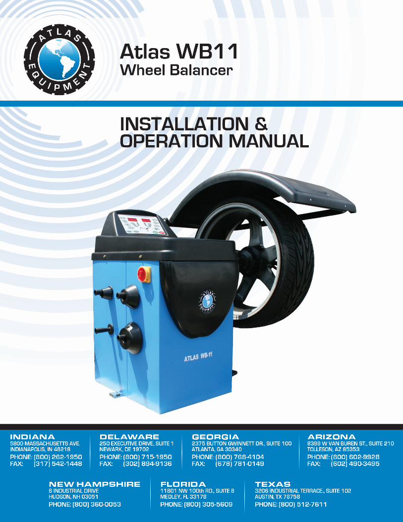
2.5 MACHINE DESCRIPTION
A: Control panel B: Wheel weight tray/cover C: Main switch D: Cone holder E: Machine body F: Feet G: Wheel guard H: Quick locking nut I: Cone adaptor J: Wheel support shaft K: Measuring gaugeL: Foot brake
2.6 TECHNICAL SPECIFICATION
Max. wheel weight 75kg Wheel diameter 39” (1000mm) Rim diameter 10" - 26" (255 - 660mm) Wheel width 1.5" - 20" (39 - 510mm) Balancing precision 1g
Resolution 1.4 degrees Cycle time 7 s Max. balancing speed 150 rpm Power supply 110V/220V/230V-1Ph Motor power 180w Noise level < 70 dbA
Fig. 1

REV. 03 7 / 22
CHAPTER 3 – TRANSPORTATION, UNPACKING AND STORAGE
3.1 TRANSPORTATION
The machine must be transported in its original packaging and kept in the position shown on the package itself.The packaged machine may be moved by means of a fork lift truck of suitable capacity. Insert the forks at the points shown in figure 2.
3.3 UNPACKING
Remove the protective cardboard and the nylon bag.Remove the fixing bolts from the packing pallet.Check that the equipment is in perfect condition, making sure that no parts are damaged or missing. Use fig. 1 for reference.
If in doubt do not use the machine and contact your retailer.
3.3 STORAGE
Packages must be stored in a covered place, out of direct sunlight and in low humidity, at a temperature between -10°C and +40°C.In the event of storage for long periods of time, be sure to disconnect all sources of power and grease the clamp sliding guides on the turntable to prevent them from oxidizing.
Fig. 2
REV. 03 8 / 22
CHAPTER 4 – COMMISSIONING
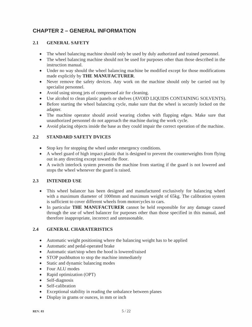
4.1 SPACE REQUIRED
When choosing the place of installation, make sure that it complies with current safety at work regulations.Do not operate the balancer while it is on the pallet.
The balancer must be located on a flat floor of solid construction, preferably concrete. The balancer must sit solidly on its three feet. If the balancer is not leveled, the balancer will not function properly and may produce inaccurate balance readings. Select a location for the balancer that provides a level, solid floor, and adequate clearance around and above the balancer. The place of installation must also provide at least the space shown in pictures Fig. 3 and Fig. 4 so as to allow all parts of the machine to operate correctly and without any restriction.Make sure the location selected has enough room above and behind the machine so the wheel guard can be raised completely. The location must also provide working room for mounting and removing wheels. Make sure the area has adequate lighting. If the machine is installed outside it must be protected by a lean-to.
4.2 SHAFT ASSEMBLY
Mount the thread end piece (A) onto the shaft by screwing the retaining screw (B).Tighten the retaining screw (B) thoroughly by using the supplied wrench (C).
Fig. 3 Fig. 4
Fig. 5
A
B
C

REV. 03 9 / 22
4.3 WHEEL GUARD MOUNTING (ref. Fig. 6)
Remove the wheel guard and installation accessories from the package. Mount the guard frame onto the guard arms fixed on the machine. Tighten the screws. Mount the wheel guard onto the guard frame. Check the micro switch is held down when the guard is closed. Adjust it if necessary.
Do not clean on the guard during the wheel balancing cycle.
4.4 ELECTRIC CONNECTION
Any electric connection job must be carried out by professionally qualified personnel.
Make sure that the power supply is right.
Make sure the connection of the phases is right. Improper electrical hook-up can damage motor and will not be covered under warranty.
The machine is supplied with a single phase mains cable plus earth (ground) Check to make sure the characteristics of your systems correspond to those required by the machine. The supply voltage (and mains frequency) is given on the machine nameplate. It cannot be changed. Connect the machine to the main electric power supply. If the machine does not include the electric plug, the user must set one, which must conforms to the voltage of the machine, in compliance with the regulations in force.The machine should not be started up without proper earthing.
Fig. 6
Wheelgaurd
Gaurdframe
MicroswitchGaurd arm
REV. 03 10 / 22
CHAPTER 5 – CONTROL PANEL AND MENU FUNCTION
5.1. CONTROL PANEL
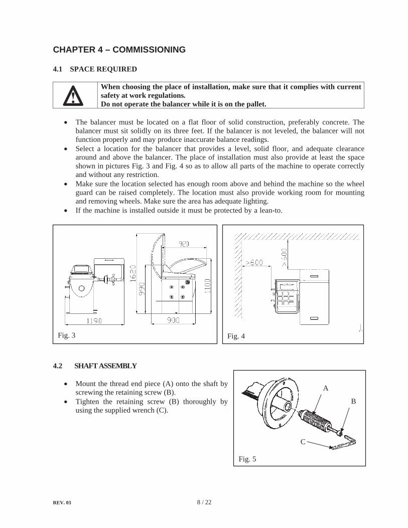
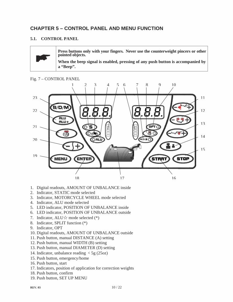
Press buttons only with your fingers. Never use the counterweight pincers or other pointed objects. When the beep signal is enabled, pressing of any push button is accompanied by a “Beep”.
Fig. 7 – CONTROL PANEL
1. Digital readouts, AMOUNT OF UNBALANCE inside 2. Indicator, STATIC mode selected 3. Indicator, MOTORCYCLE WHEEL mode selected 4. Indicator, ALU mode selected 5. LED indicator, POSITION OF UNBALANCE inside 6. LED indicator, POSITION OF UNBALANCE outside 7. Indicator, ALU mode selected (*) 8. Indicator, SPLIT function (*) 9. Indicator, OPT 10. Digital readouts, AMOUNT OF UNBALANCE outside 11. Push button, manual DISTANCE (A) setting 12. Push button, manual WIDTH (B) setting 13. Push button, manual DIAMETER (D) setting 14. Indicator, unbalance reading 5g (25oz) 15. Push button, emergency/home 16. Push button, start 17. Indicators, position of application for correction weights18. Push button, confirm 19. Push button, SET UP MENU
1 105 62 3 4 7 8 9
11
12
13
14
15
161718
19
20
21
22
23
REV. 03 11 / 22
20. Push button, FUNCTION selection 21. Push button, SPLIT selection (*) 22. Push button, ALU/ ALU mode selection (*) 23. Push button, STATIC/MOTORCYCLE WHEEL mode selection
(*) those functions are disabled in this model.
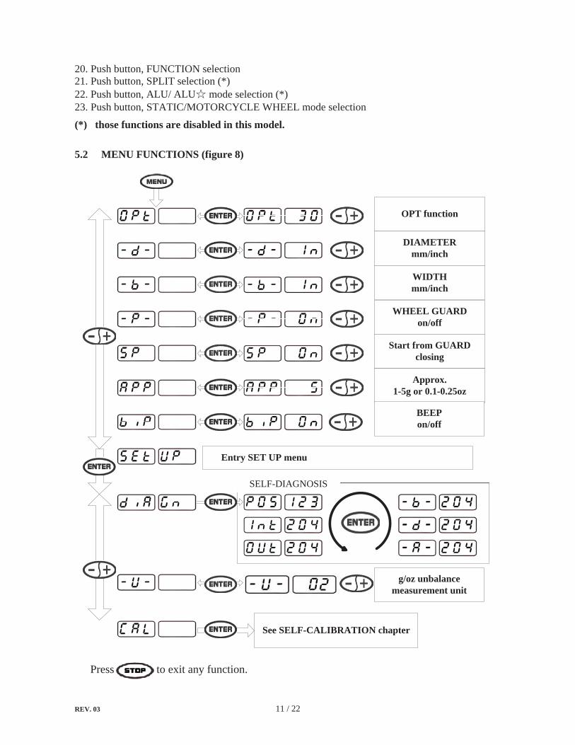
5.2 MENU FUNCTIONS (figure 8)
OPT function
DIAMETERmm/inch
WIDTHmm/inch
WHEEL GUARDon/off
Start from GUARDclosing
Approx.1-5g or 0.1-0.25oz
BEEPon/off
Entry SET UP menu
g/oz unbalancemeasurement unit
See SELF-CALIBRATION chapter
SELF-DIAGNOSIS
Press to exit any function.

REV. 03 12 / 22
CHAPTER 6 – OPERATION OF THE WHEEL BALANCER
Do not use the machine until you have read and understood the entire manual and the warning provided.
The wheel guard must not be opened before the wheel stops. The STOP button serves to stop the machine immediately in emergencies.
Do not permit the control panel to get wet!
Chains, bracelets, loose clothing or foreign objects in the vicinity of the moving parts can represent a danger for the operator.
6.1 BASIC OPERATION INFORMATION
The initial screen when switching on is in DYNAMIC mode.
Mount the wheel on the shaft of machine. Use the most appropriate mounting method. Always remove any weight attached to the wheel. Switch on the machine. Measure and entry the wheel data. Select the most appropriate balancing mode. The initial screen when switching on is in DYNAMIC mode. Start the machine. Performing a spin can be started by pressing START button or closing the wheel guard if START FROM GUARD CLOSING is enabled. When the figures have been established, the spin is automatically braked to a stop in the correction zone. After the machine stops, the unbalanced amounts are shown on the digital readouts.Rotate the wheel slowly by hand until LED indicators light up to indicate the correct angular wheel position to apply the counterweights.Apply weights on the position (12 o’clock position) for correction.With the counterweights correctly in position, restart the machine to check the correct balancing of the wheel. Reset the balancing mode referring to Fig. 8.
6.2 MOUNTING WHEEL ON SHAFT
Avoid back injury, seek assistance when lifting a heavy wheel onto the balancershaft.
Make sure to tighten the quick locking nut. Failure to do so may result in serious personal injury.
Select the most appropriate mounting method for the wheel you are balancing. Using the proper method ensures secure mounting and safe balancer operation, and prevents damage to the wheel.
REV. 03 13 / 22
On most wheels, the inner side of the wheel hub usually has the most uniform surface for wheel balancing. Always center the wheel by the most uniform shaped side of the hub to achieve the most accurate balance. Regardless of mounting type, always make sure that the wheel is forced firmly against the shaft faceplate and that the quick locking nut is tightened. To assist in centering the wheel properly, rotate the wheel and the shat while tightening the nut.
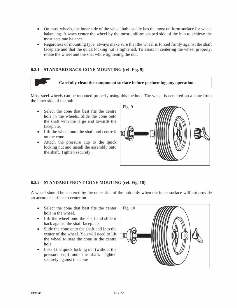
6.2.1 STANDARD BACK CONE MOUNTING (ref. Fig. 9)
Carefully clean the component surface before performing any operation.
Most steel wheels can be mounted properly using this method. The wheel is centered on a cone from the inner side of the hub.
Select the cone that best fits the centre hole in the wheels. Slide the cone onto the shaft with the large end towards the faceplate.Lift the wheel onto the shaft and centre it on the cone. Attach the pressure cup to the quick locking nut and install the assembly onto the shaft. Tighten securely.
6.2.2 STANDARD FRONT CONE MOUTING (ref. Fig. 10)
A wheel should be centered by the outer side of the hub only when the inner surface will not provide an accurate surface to center on.
Select the cone that best fits the center hole in the wheel. Lift the wheel onto the shaft and slide it back against the shaft faceplate. Slide the cone onto the shaft and into the center of the wheel. You will need to lift the wheel to seat the cone in the centre hole.Install the quick locking nut (without the pressure cup) onto the shaft. Tighten securely against the cone
Fig. 9
Fig. 10

REV. 03 14 / 22
6.3 WHEEL DATA ENTRY
Before balancing a wheel, wheel data must be entered into the processor.
6.3.1 WHEEL DATA
6.3.2 MANUAL ENTRY (ref. Fig. 13)
Measure the distance from the machine (“0” on the gauge) to the inner side of the rim as shown in the figure 11. Entry the data manually. Measure the width at the rim with the supplied caliper as shown in the figure 12. Entry the data manually. Check the diameter indicated on the rim. Entry the data manually.
A: The distance, measured from the machine to the inner side of the rim
Fig. 11
B: The wheel width
D: The wheel diameter
Fig. 12
Fig. 13

REV. 03 15 / 22
6.4 BALANCING MODE
6.4.1 DYNAMIC MODE
The dynamic mode is used for most passenger and light truck wheels using the most common location for corrective weights. Clip-on weights are placed on the inner and outer sides of the rim.
On the initial screen press
Fig. 14
Correction of outer side Correction of inner side
6.4.2 STATIC MODE
The static mode is used for motorcycles or narrow wheels when it is not possible to place the counterweights on both sides of the rim. Clip a single weight on one of sides of the rim or in centre of wheel according to the diameter of the wheel mounted.
Press to select “Static mode” when the LED indicator lights up and then press
Fig. 15

REV. 03 16 / 22
6.4.3 STANDARD ALU MODE
All the ALU modes are dynamic balance. Choose the option that best fits the available locations as shown in the figure 16.
From the measurement screen, press to select the modes ALU1 ALU2 ALU3 ALU4.
Fig. 16
Balancing of light alloy rims with application of adhesive weights on the rim shoulders.Both weight positions are fixed.
Balancing of light alloy rims with hidden application of adhesive weights.Outer weight position is fixed.
Combination application: clip-on weight inside and hidden adhesive weight on outside.Outer weight position is same as ALU2.
Combination application: adhesive weight outside and clip-on weight inside. Outer weight position is same as ALU1.

REV. 03 17 / 22
6.4.4 UNBALANCE OPTIMIZATION (OPT)
This function is used to determine the best mating of tire and rim that will result in the least amount of total unbalance of the wheel. It severs to reduce the amount of weight to be added in order to balance the wheel. It is suitable for static unbalance exceeding 30g.
A high unbalance may indicate the improper mounting of the wheel on the balancer. If the unbalance is excessive, it may be prudent to replace the rim, the tire, o both. If either is replaced, do not continue with optimization. Balance the new tire and rim and evaluate the readings.
After performing the static balance, press . If the unbalance amount shown on the digital readouts is exceeding 30g, the digital readouts display “YES” “OPT”. In this case, start OPT function:
Mark with chalk reference points on the same position of both the tire and the rim. Rotate the wheel to move the marked points to 12 o’clock position. Press to memorize the position. Remove the wheel from the balancer. Remove the tire from the rim with the aid of a tire changer. Only mount the rim on the balancer. Rotate the rim to move the mark to 12 o’clock position. Press to spin the rim.
After performing the spin:
Rotate the rim until LED indicator for outside (Fig. 7 – 6) lights up. Mark with chalk on the rim at 12 o’clock position. With the aid of the tire changer, refit the wheel with the reference marks coinciding between the rim and tire.
REV. 03 18 / 22
Diagnosis of phase
Diagnosis of inner piezo
Diagnosis of outer piezo
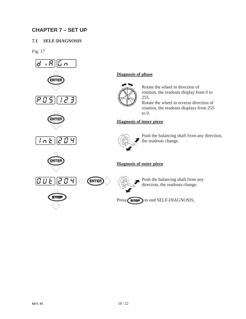
Press to end SELF-DIAGNOSIS,
CHAPTER 7 – SET UP
7.1 SELF-DIAGNOSIS
Fig. 17
Rotate the wheel in direction of rotation, the readouts display from 0 to 255.Rotate the wheel in reverse direction of rotation, the readouts displays from 255 to 0.
Push the balancing shaft from any direction, the readouts change.
Push the balancing shaft from any direction, the readouts change.
REV. 03 19 / 22
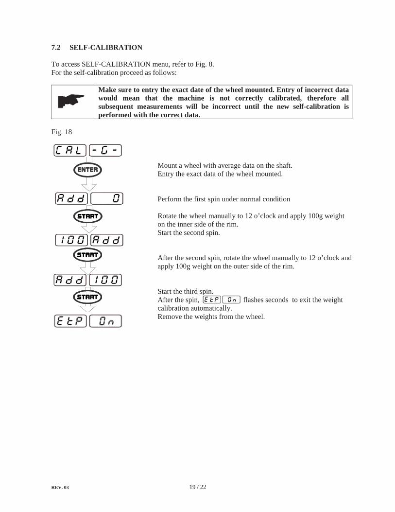
7.2 SELF-CALIBRATION
To access SELF-CALIBRATION menu, refer to Fig. 8. For the self-calibration proceed as follows:
Make sure to entry the exact date of the wheel mounted. Entry of incorrect data would mean that the machine is not correctly calibrated, therefore all subsequent measurements will be incorrect until the new self-calibration is performed with the correct data.
Fig. 18
Mount a wheel with average data on the shaft. Entry the exact data of the wheel mounted.
Perform the first spin under normal condition
Rotate the wheel manually to 12 o’clock and apply 100g weight on the inner side of the rim. Start the second spin.
After the second spin, rotate the wheel manually to 12 o’clock and apply 100g weight on the outer side of the rim.
Start the third spin. After the spin, flashes seconds to exit the weight calibration automatically. Remove the weights from the wheel.
REV. 03 20 / 22
CHAPTER 8 – MAINTENANCE
8.1 GENERAL WARNINGS
Unauthorized personnel may not carry out maintenance work.
Regular maintenance as described in the manual is essential for correct operation and long lifetime of the tire changer. If maintenance is not carried out regularly, the operation and reliability of the machine may be compromised.
Before carrying out any maintenance work, disconnect the electric supply.
Do not clean the machine with compressed air or jet of water.
Defective parts must be replaced exclusively by expert personnel using the manufacturer’s parts.Removing or tampering with safety devices is extremely forbidden.
In particular, the Manufacturer shall not be held responsible for complaints deriving from the use of spare parts made by other manufacturers or for damage caused by tampering or removal of safety systems.
8.2 ORDINARY MAINTENANCE
This balancer requires only minor maintenance to keep the machine operating properly.
Keep the area around the machine clear. Keep the display clean and clear. Use a vaporizing cleaner only. Do not use cleaners or the solvents which leave oil or firmly residues behind. Keep the adaptors, cones, thread shaft, pressure cup, and the quick locking nut clean. Grease and dirt buildup will cause inaccurate balancing and premature wear. Clean these items at once a day using a vaporizing solvent.Clean the weight tray, the cone holders and accessories using a vaporizing solvent. Weights stored in a dirty tray may pick up grease and dirt which may keep them from attaching to the wheel securely.

REV. 03 21 / 22
CHAPTER 9 – ERRORS AND TROUBLE-SHOOTING
9.1 ERROR DISPLAY
During machine operation, various cause of faulty operation can occur. If defected by the micro-processor, they appear on the display as follows:
ERRORS: MEANING: SOLUTION:
Err -0- The machine is not preset up by the manufacturer before delivery.
Call for the technical service.
Err -CAL- Faulty calibration. Recalculation. Err -2- Speed too low during balancing measurement
spin.Check the driven belt Check the bearings Check the motor Check the quick locking nut tightness
Err -5- Micro switch is not adjsuted properly or defcetive.
Check and adjust it or replace it if necessary.
Err -6- The balancing measurement spin is stopped by carelessness.
9.2 TROUBLE-SHOOTING
TROUBLE: POSSIBLE CAUSE: SOLUTION:No display when switching on
1. There is no power. 2. The faulty power plug. 3. The electrical wires are
disconnected.4. Wrong power voltage. 5. Fuses are blown.
1. Check power on. 2. Replace. 3. Reconnect. 4. Check for correct voltage. 5. Replace.
The diameter measured is not correct.
1. The gauge is not positioned correctly when measuring.
2. The gauge is not calibrated.
1. Position the gauge correctly. 2. Calibrate the gauge.
The measurement gauge cannot function properly.
1. The gauge fails to return onto its orginal position automatically.
1. Reset the gauge.2. Switch off and switch on the
machine again The machine does not spin when the wheel guard is closing.
1. The function “start from the guard closing” is not enabled.
2. The wheel guard is not closed completely.
3. The electric wire for the micro switch is disconnected.
4. The micro switch is not adjusted properly or faulty.
1. Enable the function if necessary.
2. Close the guard completely. 3. Reconnect. 4. Check for correct adjustment
or replace it if necessary.
Inconsistent unbalance reading
1. The machine is shocked. 2. The machine is not rested solidly. 3. The wheel is not tightened. 4. Wrong data entry. 5. The machine is not calibrated.
1. Do not shock the machine and restart a spin.
2. Sit the machine solidly. 3. Tighten the wheel. 4. Entry the correcgt data. 5. Calculate the machine.

REV. 03 22 / 22
CHAPTER 10 – ELECTRIC DIAGRAM
(+) red
(+) red-)black
Phase encoder
1 phase motor
Capacitor
Power transform
er
Braking transform
er
Power board
Micro sw
itch
Power sw
itch
CPU
Digital readouts
Outer
piezo
Innerpiezo
(-) black
(+) red (-) black
(+) red-)black
Key pad
LN
PE
LN
M

WarrantyThis item has a one (1) year LIMITED warranty.
Atlas® Automotive Equipment warrants the equipment to the original purchaser against defects in material or workmanship under normal use for a period of one year from the date of purchase. This warranty shall be limited to the replacement of materials or parts found defective, at the discretion of Atlas®
Automotive Equipment and/or its authorized distributors. This limited one (1) year warranty DOES NOT apply to normal wear items (turntable jaws, belts, gauges, plastic jaw protectors, etc.). The limited one (1) year warranty does not include a labor warranty. Warranties do not apply to items that have been abused or misused.
Returned goods must be authorized to be returned (in writing) by Atlas® Automotive Equipment and/or an authorized distributor and must be prepaid to a designated location. All returns may be subject to a 15% handling and restocking charge. Returned goods must be in like-new condition complete with warranty and original shipping papers.
Customer’s Responsibilities
• Shall ensure that all air operated components are properly maintained• Shall ensure components are powered by well lubricated and moisture free compressed air
(if a suspected defective part has not been properly lubricated it will not be covered under warranty)
• Shall establish procedures to periodically maintain and inspect the equipment• Shall ensure that your wheel balancer is protected by a surge protector• Shall ensure that all equipment shall have adequate amperage service
THIS WARRANTY IS EXCLUSIVE AND IS LIEU OF ALL OTHER WARRANTIES EXPRESSED OR IMPLIED INCLUDING ANY IMPLIED WARRANTY OR MERCHANTABILITY OR ANY IMPLIED WARRANTY OF FITNESS FROM A PARTICULAR PURPOSE, AND ALL SUCH IMPLIED WARRANTIES ARE EXPRESSLY EXCLUDED.
THE REMEDIES DESCRIBED ARE EXCLUSIVE AND IN NO EVENT SHALL THE MANUFACTURER, NOR ANY SALES AGENT OR OTHER COMPANY AFFILIATED WITH IT OR THEM, BE LIABLE FOR SPECIAL CONSEQUENTIAL OR INCIDENTAL DAMAGES FOR THE BREACH OF OR DELAY IN PERFORMANCE OF THIS WARRANTY. THIS INCLUDES, BUT IS NOT LIMITED TO, LOSS OF PROFIT, RENTAL OR SUBSTITUTE EQUIPMENT OR OTHER COMMERCIAL LOSS.
For warranty assistance, please call 866-898-2604. Please have your invoice number ready so that we may be able to serve you better. Warranty procedures cannot be initiated without an invoice number corresponding to the product serial number.
For further product and distributor information, please visit www.atlasautoequipment.com