Embed Size (px)
Citation preview

CONFIDENTIAL 1
Presented by: John Coonrod
Printed Circuit Board (PCB) High Frequency Materials, Impact on Radar Sensor Performance
Designing a 77 GHz Radar Sensor ? Have you considered you Printed Circuit Board Influence ?
CONFIDENTIAL 2
Printed Circuit Board (PCB) High Frequency Materials, Impact on Radar Sensor Performance
Agenda
• Introduction
• Simple overview of Printed Circuit Board (PCB) technology
• How PCB’s can influence 77 GHz radar sensors
• Critical properties of the high frequency circuit materials used to make PCB’s
• Examples of RF PCB performance at 77 GHz, using different circuit materials
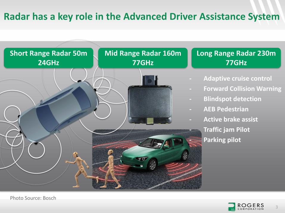
Radar has a key role in the Advanced Driver Assistance System
3
Short Range Radar 50m 24GHz
Mid Range Radar 160m77GHz
Long Range Radar 230m77GHz
Photo Source: Bosch
- Adaptive cruise control
- Forward Collision Warning
- Blindspot detection
- AEB Pedestrian
- Active brake assist
- Traffic jam Pilot
- Parking pilot
CONFIDENTIAL 4
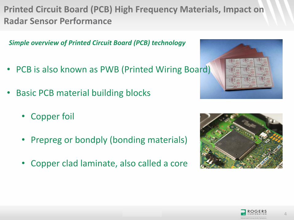
Printed Circuit Board (PCB) High Frequency Materials, Impact on Radar Sensor Performance
Simple overview of Printed Circuit Board (PCB) technology
• PCB is also known as PWB (Printed Wiring Board)
• Basic PCB material building blocks
• Copper foil
• Prepreg or bondply (bonding materials)
• Copper clad laminate, also called a core
CONFIDENTIAL 5
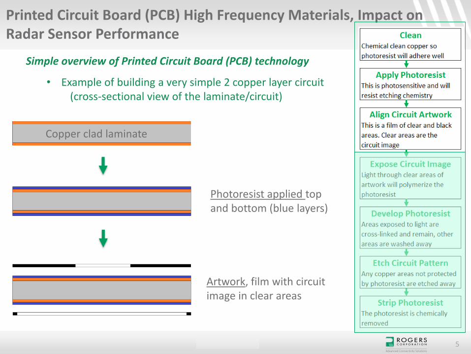
Printed Circuit Board (PCB) High Frequency Materials, Impact on Radar Sensor Performance
Simple overview of Printed Circuit Board (PCB) technology
Copper clad laminate
Photoresist applied top and bottom (blue layers)
Artwork, film with circuit image in clear areas
• Example of building a very simple 2 copper layer circuit(cross-sectional view of the laminate/circuit)
CONFIDENTIAL 6
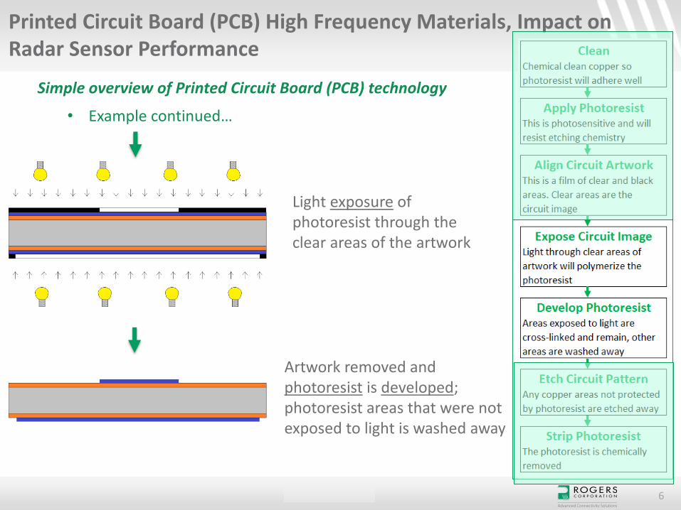
Printed Circuit Board (PCB) High Frequency Materials, Impact on Radar Sensor Performance
Simple overview of Printed Circuit Board (PCB) technology
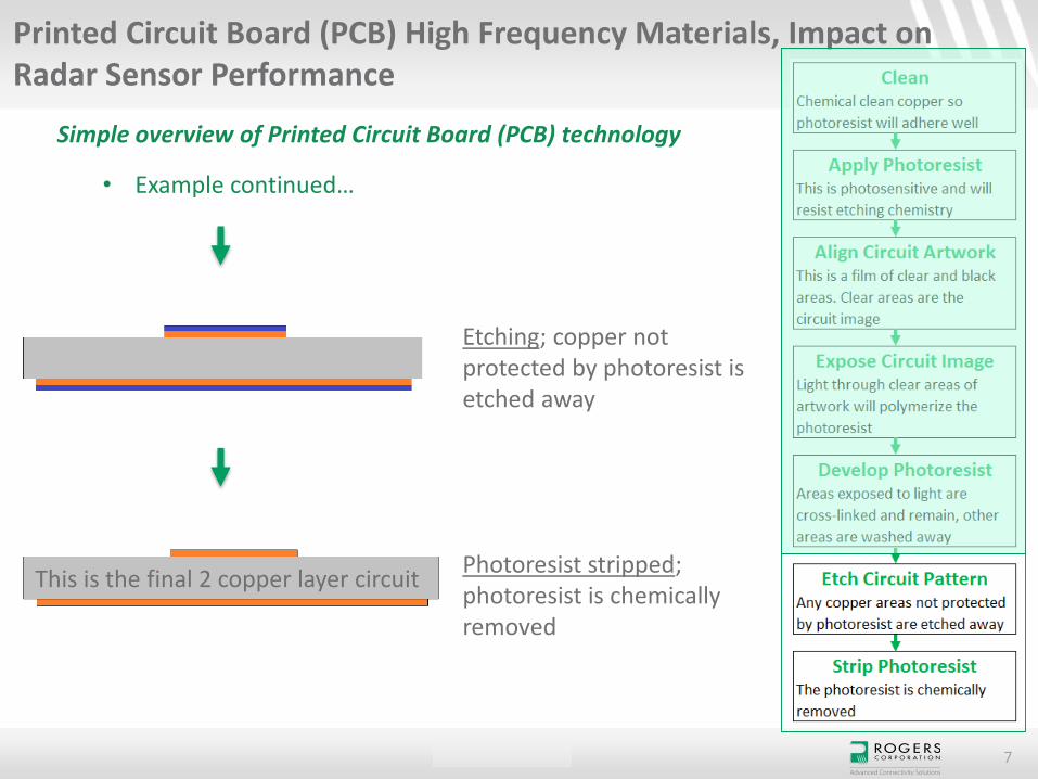
• Example continued…
Light exposure of photoresist through the clear areas of the artwork
Artwork removed and photoresist is developed; photoresist areas that were not exposed to light is washed away
CONFIDENTIAL 7
Printed Circuit Board (PCB) High Frequency Materials, Impact on Radar Sensor Performance
Simple overview of Printed Circuit Board (PCB) technology
Etching; copper not protected by photoresist is etched away
Photoresist stripped; photoresist is chemically removed
This is the final 2 copper layer circuit
• Example continued…
CONFIDENTIAL 8
Printed Circuit Board (PCB) High Frequency Materials, Impact on Radar Sensor Performance
Simple overview of Printed Circuit Board (PCB) technology
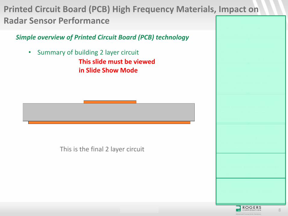
• Summary of building 2 layer circuit
This is the final 2 layer circuit
This slide must be viewed in Slide Show Mode

CONFIDENTIAL 9
Printed Circuit Board (PCB) High Frequency Materials, Impact on Radar Sensor Performance
Simple overview of Printed Circuit Board (PCB) technology
Cross-sectional view of microstrip circuit using 12mil RO4003B™ laminate
3D view of microstrip circuit
For high frequency RF applications, a 2 layer circuit is a microstrip circuit. The top copper layer will be the signal conductor and the bottom copper layer is the ground plane
CONFIDENTIAL 10
Printed Circuit Board (PCB) High Frequency Materials, Impact on Radar Sensor Performance
Simple overview of Printed Circuit Board (PCB) technology
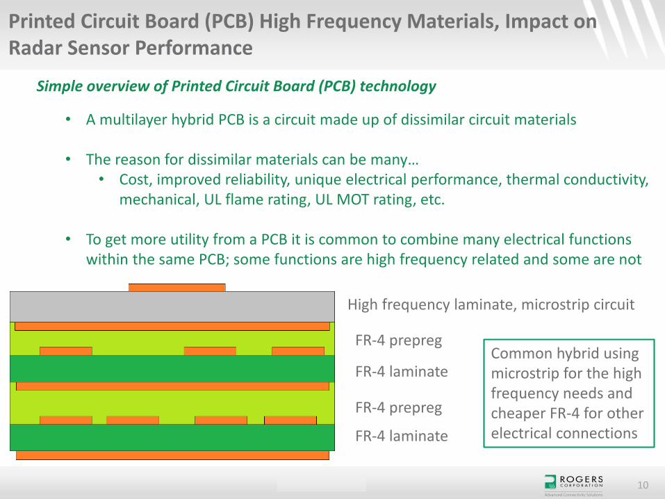
• A multilayer hybrid PCB is a circuit made up of dissimilar circuit materials
• The reason for dissimilar materials can be many…• Cost, improved reliability, unique electrical performance, thermal conductivity,
mechanical, UL flame rating, UL MOT rating, etc.
• To get more utility from a PCB it is common to combine many electrical functions within the same PCB; some functions are high frequency related and some are not
High frequency laminate, microstrip circuit
FR-4 prepreg
FR-4 laminate
FR-4 prepreg
FR-4 laminate
Common hybrid using microstrip for the high frequency needs and cheaper FR-4 for other electrical connections
CONFIDENTIAL 11
Printed Circuit Board (PCB) High Frequency Materials, Impact on Radar Sensor Performance
Simple overview of Printed Circuit Board (PCB) technology
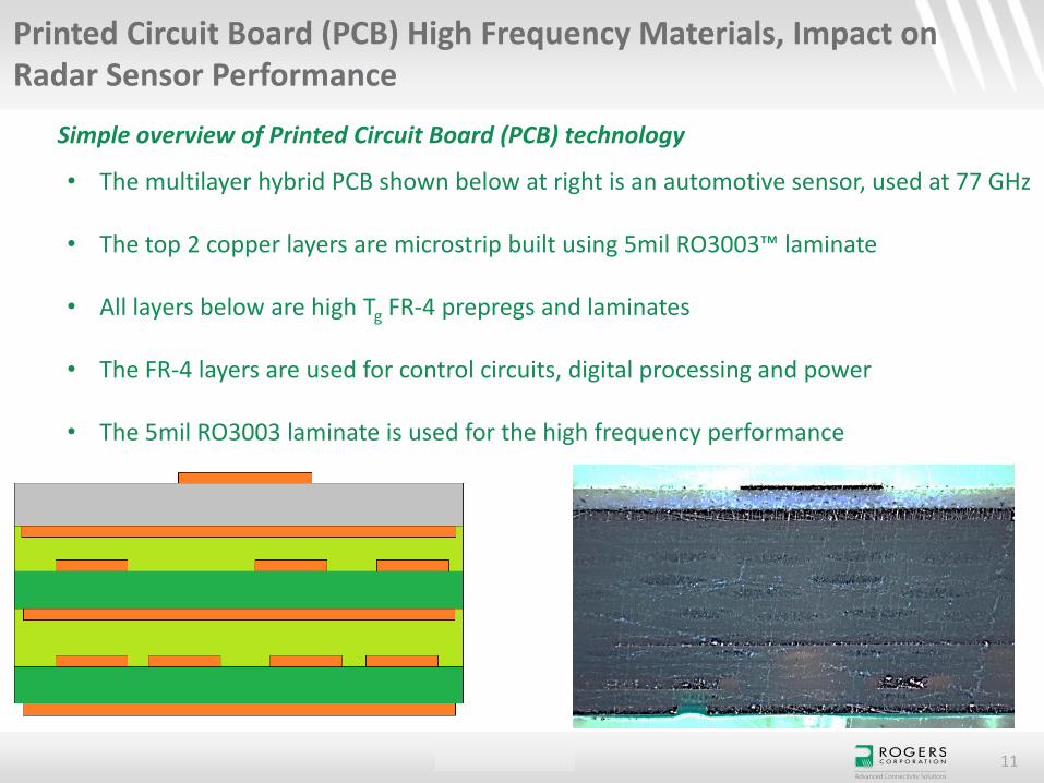
• The multilayer hybrid PCB shown below at right is an automotive sensor, used at 77 GHz
• The top 2 copper layers are microstrip built using 5mil RO3003™ laminate
• All layers below are high Tg FR-4 prepregs and laminates
• The FR-4 layers are used for control circuits, digital processing and power
• The 5mil RO3003 laminate is used for the high frequency performance
CONFIDENTIAL 12
Printed Circuit Board (PCB) High Frequency Materials, Impact on Radar Sensor Performance
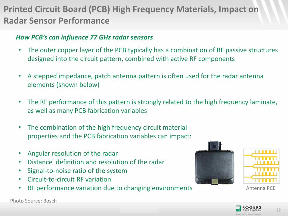
How PCB’s can influence 77 GHz radar sensors
• The outer copper layer of the PCB typically has a combination of RF passive structures designed into the circuit pattern, combined with active RF components
• A stepped impedance, patch antenna pattern is often used for the radar antenna elements (shown below)
• The RF performance of this pattern is strongly related to the high frequency laminate, as well as many PCB fabrication variables
• The combination of the high frequency circuit material properties and the PCB fabrication variables can impact:
• Angular resolution of the radar• Distance definition and resolution of the radar• Signal-to-noise ratio of the system• Circuit-to-circuit RF variation• RF performance variation due to changing environments Antenna PCB
Photo Source: Bosch
CONFIDENTIAL 13
Printed Circuit Board (PCB) High Frequency Materials, Impact on Radar Sensor Performance
How PCB’s can influence 77 GHz radar sensors
• The high frequency material used to make the PCB also have several properties which can impact RF performance for radar sensors
• Dk (Dielectric constant) control• Df (Dissipation factor)• Moisture absorption• Copper surface roughness• TCDk (Thermal Coefficient of Dielectric Constant)
• Some PCB fabrication variables which can impact RF performance are:
• Copper etching accuracy• Copper plating thickness variation• Via connections to other circuit layers• Final plated finish• Soldermask • Various wet chemistries used to make the PCB
CONFIDENTIAL 14
Printed Circuit Board (PCB) High Frequency Materials, Impact on Radar Sensor Performance
Critical properties of high frequency circuit materials used to make PCB’s
• Dielectric constant (Dk) tolerance• Tightly controlled Dk tolerance enables more consistent performance; ± 0.05 is good
• Dissipation factor (Df)• Most mmWave circuits are thin so conductor effects dominate, but at higher
frequencies Df does have an impact on loss; Df < 0.0035 is good
• Copper surface roughness• Smoother is better for reducing loss and having more consistent phase response
• Moisture absorption• Moisture will increase losses and alter the Dk of the circuit; less than 0.2% is good
• Temperature Coefficient of Dielectric Constant (TCDk)• All materials change Dk with change in temperature; typically TCDk < 50 ppm/°C is good
• Woven-glass reinforcement• Some glass are better/worse for laser via’s and the glass-weave effect; no glass is best
CONFIDENTIAL 15
Printed Circuit Board (PCB) High Frequency Materials, Impact on Radar Sensor Performance
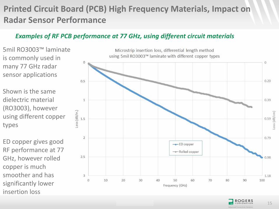
Examples of RF PCB performance at 77 GHz, using different circuit materials
5mil RO3003™ laminate is commonly used in many 77 GHz radar sensor applications
Shown is the same dielectric material (RO3003), however using different copper types
ED copper gives good RF performance at 77 GHz, however rolled copper is much smoother and has significantly lower insertion loss

CONFIDENTIAL 16
Printed Circuit Board (PCB) High Frequency Materials, Impact on Radar Sensor Performance
Examples of RF PCB performance at 77 GHz, using different circuit materials
Comparison of two different high frequency materials
The I_a is not a Rogers material and is a thermoset material
The moisture absorption is much higher for the I_amaterial than the RO3003 material
The higher moisture absorption impacts the insertion loss (shown here) but also impacts the phase response (not shown)

CONFIDENTIAL 17
Become a Member of the Technology Support Hub for additional technical tools & information
Access:
Microwave Impedance Calculator
ROG Mobile App
Electrical & Thermal Calculators
Engineering Support
Technical Papers
Videos
Sign up to receive email updates to be kept up to date on recently released products.