Embed Size (px)
Citation preview
March 29, 2014 14:33 WSPC - Proceedings Trim Size: 9in x 6in main
1
Printable Modular Robot:
An Application of Rapid Prototyping for Flexible Robot Design
Dennis Krupke, Florens Wasserfall, Norman Hendrich and Jianwei Zhang
Department of Informatics, Group TAMS, University of Hamburg,Hamburg, Germany
E-mail: {florens.wasserfall, dennis.krupke, hendrich,
zhang}@informatik.uni-hamburg.dehttp://tams.informatik.uni-hamburg.de
This paper presents a novel design for a modular snake-like robot with mag-
netic coupling between the modules. Each module combines 3D-printed me-
chanical parts with widely available standard electronic components, resultingin a highly customizable, low-cost robot platform for research and education.
Since simulation and 3D-printing rely on the same model-files, the design also
integrates smoothly into simulation environments like OpenRAVE. The robotcan be assembled and re-assembled on the fly. Automatic topology detection is
realized with custom connection-interfaces and dynamic initialization of inter-
module communication.
Keywords: Modular robot; Rapid prototyping; Topology detection.
1. Introduction
Rapid prototyping and 3D-printing in particular have become an ubiqui-
tous topic in the last decade and the technology to generate free-form parts
on demand is now available to basically every researcher and engineer. In
this paper, we describe our approach to create an open source, easy to
prototype modular robot, intended for use in research and education. The
modules are optimized for printing and include only standard hardware
parts. Module attachment is realized via a novel design that uses magnets
for both the mechanical and the electrical interconnection.
All module specifications and design files are open source, allowing stu-
dents to develop and modify the design and thus learn how to go about
creating a robot. The basic design criteria are inspired by the work of
Juan Gonzalez-Gomez and his Miniskybot1 project. The proposed robot is
designed for chain-configurations, where the modules can be connected in
March 29, 2014 14:33 WSPC - Proceedings Trim Size: 9in x 6in main
2
arbitrary pitching and yawing joint configurations.2,3 According to the clas-
sification of reconfigurable modular robots by Murata et al,4 the proposed
robot is positioned between class 2 and class 3, as a semi-self-reconfigurable
modular robot. Reconfiguring the physical topology requires manual inter-
action, but can be performed during operation. The robot automatically
recognizes its topology and actively adopts changes to the running locomo-
tion patterns.
2. From simulation to reality and back
Based on previous work,5 we used an extension of the OpenRAVE6 sim-
ulation framework for the optimization of the modular robot design and
locomotion. To simulate the behaviour of servo motors, the OpenMR7 plu-
gin is utilized. Realistic robot motion is calculated by the ODE physics
engine.8 Arbitrary robot models are easy to integrate into this system, be-
cause standardized robot definition files are used to define a robot from
3D-model-files and joint definitions. The very same 3D-models (.stl files)
are used for both, the simulation system and the 3D-printing. Thus, simu-
lation automatically captures the mechanical properties of the real housing
of a specific robot module. The system has been used to create, test and
optimize the generation of locomotion patterns, based on the specific con-
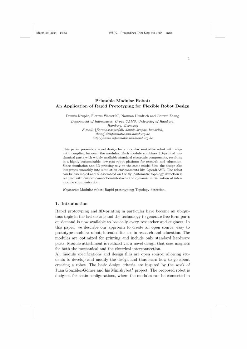
figuration of the robot. Fig. 1 shows a simulated robot in locomotion with
the same 3D-models that have been printed to create the real robot. This
concept allows for simulation and reality to be as close as possible. The
close coupling of 3D models, simulation and real hardware substantially
Fig. 1. Left: evolution steps of part design. Right: simulator for locomotion of modularrobots, showing a robot built with the printable 3D-models.

March 29, 2014 14:33 WSPC - Proceedings Trim Size: 9in x 6in main
3
aids the development process. Robots created only for simulation can be
printed if they were successful in simulations. In turn, existing robots can
be simulated (if their 3D models are available) and possibly modified to
achieve better results for the next production series. Figure 1 shows a se-
ries of three iterations of improvement of one part of the robot, with the
inner magnets added during the second generation and increased thickness
of the base for precise alignment of the magnets in the final design.
3. Module hardware and design
The printable 3D-models for the plastic parts of the robot are designed
in OpenSCAD. OpenSCAD is an open source solid 3D CAD modelling
system for programmers. Objects are created with Constructive Solid Ge-
ometry (CSG), using a scripting language. Standard components like nuts,
servos and microcontroller boards are directly integrated into the module
design. They can be easily applied after printing and fit accurately into the
custom shaped slots. Parametrization in the scripting language allows for
creating generic packages in a way, that they can be reused for different
sized modules and additional hardware.
Each module consists of at least three printed plastic parts. The battery slot
is prepared to attach printed tactile feet sensors by a snap-in mechanism.
Single modules are mechanically connected by permanent magnets for a fast
and easy change of topology. These magnets also provide electrical contacts
between adjacent modules on the outer side and to the internal wiring on
the inner side, by locking the ferromagnetic screws in place, which are at-
tached to the wires. Communication is implemented via serial interfaces
which are integrated into Arduino boards in hardware and software.
Fig. 2. Left: Assembled robot with 4 modules. Right: Standard components needed
for one module.

March 29, 2014 14:33 WSPC - Proceedings Trim Size: 9in x 6in main
4
3.1. 3D-Printer
The 3D-printer used for this project is a custom designed device, based on
the Reprap design.9 The design has been extended to support simultaneous
printing with at least 3 extruders for a wide range of extruder characteristics
and materials. Objects can be printed from PLA- or ABS-plastic. PVA is
used for water soluble support structures. We incorporated experimental
adaptive slicing algorithms to achieve high precision prints on affordable
hardware. The resolution of the printer’s z-axis and extrusion diameter is
dynamically modified, depending on the local structure of the object.
3.2. Hardware components
Each module combines the printed mechanical parts, one servo for locomo-
tion, one Arduino Nano V3 board for control and one extension slot, which
either holds a battery (right picture in fig. 2) or other hardware, partic-
ularly sensors. The batteries are connected in parallel as a shared power
supply. This allows a subset of modules to operate autonomously but does
not require a battery on every module to save space for sensors or other
cargo. The Arduino Nano controller was chosen for its small form factor
and affordable price, as well as the extensive collection of open-source soft-
ware and drivers. It also benefits from easy programmability via USB us-
ing the Arduino IDE. All hardware components are open-source (Arduino,
CAD-models) or at least standardized parts (servos, magnets). Important
specifications of the components are summarized in table 1.
Table 1. Specifications of the robot
Control board Arduino Nano V3 (ATmega328p, 16MHz, 32KB flash memory)
Servo Micro servo (Tower Pro MG90, 2 kg/cm torque at 4.8V )
Weight ≈ 0.12 kg (completely assembled)
Power supply Low cost two-cell LiPo batteries (7.4V, 820mAh)
Magnets Neodymium (N52, r=3mm, h=2mm, ≤ 2kg force)
Price 15-20 Euro (per module)
3.3. Magnetic Module Interconnection
The key feature of the robot is the combined mechanical and electrical
module attachment via a set of eight magnets on each end of the module,
see figure 4.
March 29, 2014 14:33 WSPC - Proceedings Trim Size: 9in x 6in main
5
Screw
Nut
Magnet
Printed Part
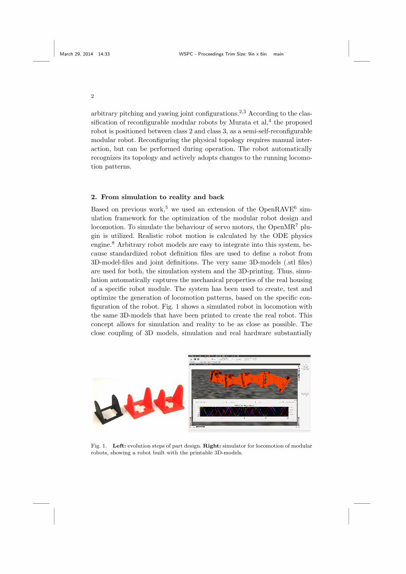
Fig. 3. Magnetic connector.
The internal wiring is realized with standard
ferromagnetic screws and nuts, attached to the
wires and hold in their slots by the magnets
(fig. 3). The batteries are connected in paral-
lel as a shared power supply to allow a subsets
of modules to operate autonomously without
consuming the entire cargo capacity. Due to
the precise alignment of the magnets in the
printed parts, the contact force generated by
the magnets is strong enough to reliably connect the modules during robot
movements. On the other hand, the user can connect and disconnect mod-
ules easily at any time and without tools. To allow dynamic changes of the
modules’ pitch/yaw orientation, a special hardware and software interface
was designed. Requirements were a rotatable pin layout and dynamic initial-
isation of the communication lines. The faceplates are physically genderless,
but logically directed (by the UART-assignment). To prevent invalid rota-
tions (shorting VCC and GND), an additional bolt and two corresponding
holes are added to the faceplates. Note that attaching two faceplates of the
same type is impossible anyway due to the magnets’ polarization.
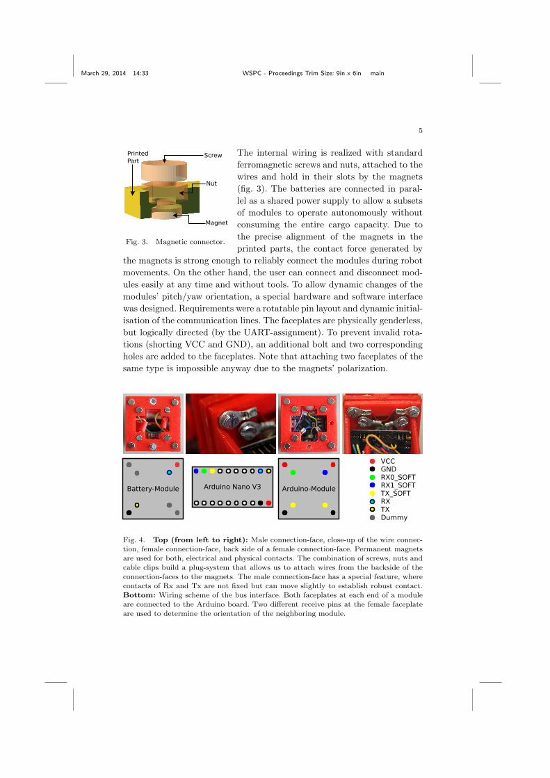
Arduino Nano V3 Arduino-ModuleBattery-Module
RX0_SOFT RX1_SOFT
VCC GND
TX_SOFT
TX RX
Dummy
Fig. 4. Top (from left to right): Male connection-face, close-up of the wire connec-
tion, female connection-face, back side of a female connection-face. Permanent magnetsare used for both, electrical and physical contacts. The combination of screws, nuts andcable clips build a plug-system that allows us to attach wires from the backside of the
connection-faces to the magnets. The male connection-face has a special feature, wherecontacts of Rx and Tx are not fixed but can move slightly to establish robust contact.
Bottom: Wiring scheme of the bus interface. Both faceplates at each end of a module
are connected to the Arduino board. Two different receive pins at the female faceplateare used to determine the orientation of the neighboring module.

March 29, 2014 14:33 WSPC - Proceedings Trim Size: 9in x 6in main
6
4. Control architecture
One robot consists of a master-module, located at one end of the chain, and
a number of 0-14 slave modulesa. Technically, every module is able to act
as master, depending on the software configuration. Due to the Arduino’s
limited computing power, it is necessary to connect an external controller
for remote control or real-world applications. This occupies one of the two
possible UART-interfaces and therefore requires the master to reside at the
end of the chain. An external controller can be carried inside the master’s
cargo-slot for autonomous operation, or connected wireless by bluetooth.
4.1. Topology
The robot is organized in a semi-dynamic master-slave-architecture. Every
node has a unique adress, assigned in software during the programming
process. The master node stores current information about order and ori-
entation of every attached module.
Localcontroller
Remotecontroller
Upstream(rx)
(rx)
(tx)
(tx)
Downstream
Module 0(master)
Module 1(slave)
Module 2(slave)
Module N-1(slave)
Hardware Serial Interface
Software Serial Interface
Fig. 5. Diagram of the robot’s hardware- and communication topology. The master
module is required to be at the end of the chain. It is usually connected to an externalcontroller by serial interface: either directly to an on-board micro-controller (Local con-
troller), or via Bluetooth/USB to stationary hardware (Remote controller). Every pairof modules is connected by a combination of one hardware- and one software-UART, to
allow for dynamic pin assignment and pitch/yaw topology detection.
The modules are wired in a daisy-chain configuration. Inter-module com-
munication is realized via serial interfaces (UART) as described in 3.3.
Modules are connected pairwise by one hardware UART and one software
UART (fig. 5), with the hardware UART facing in the master’s direction.
aThe number of modules is limited by the current protocol’s address space of 4bit. Ahigher number of modules is possible with a modified protocol.
March 29, 2014 14:33 WSPC - Proceedings Trim Size: 9in x 6in main
7
A module first initializes the hardware UART and waits for an incoming
connection request. After successfully establishing the connection, it alter-
nately probes the two software UART pins for messages from a successor
module, implicitly determining its relative orientation. The established con-
nections are periodically probed by heartbeat messages between adjacent
modules to determine breakups and changes in topology. Every change in
topology gets propagated upstream to the master, triggering an adaption
of the locomotion pattern. A loss of connection to the master module gets
propagated to every downstream module as well. Every detached module
disconnects completely and waits for a new incoming connection request
at the upstream UART. The connection chain always extends downstream,
beginning at the master module. Removing and adding modules can be
performed at any time during operation, without stopping the currently
executed locomotion.
The current version of the Arduino software serial library allows dy-
namic pin assignment but only supports half-duplex communication. The
interrupt-routines are disabled during a write operation, and incoming data
may be lost. To overcome this problem, important messages have to be ac-
knowledged and are retransmitted when lost.
4.2. Communication protocol
The communication protocol consists of two layers: one for internal com-
munication and one for communication between master node and external
controller. The instruction set of the internal protocol is a subset of the
external ones.
Internal 5-byte messages: 4 bit address, 2 bit flags, 6 bit command type,
12 bit message value and start/end sequence. The address-field is
evaluated depending on the messages’ direction. In a downstream
message (read on the hardware UART), it denotes the receiver.
Since upstream messages are always bound for the master, the ad-
dress field can be used for the sender-address. Operations on every
module can be performed as broadcasts.
External External messages are ASCII encoded. The master implements
a number of high-level commands, as ”run” or ”stop” with param-
eters to modify phase, amplitude etc.
To provide full external control, every low-level command is ac-
cepted and translated to the internal format by the master.
March 29, 2014 14:33 WSPC - Proceedings Trim Size: 9in x 6in main
8
4.3. Performance of the communication protocol
The serial connections were tested to work reliably at transfer rates up to
19200 baud, while higher rates require improvements to the software serial
library. The length of one message is 5·8 bit+5·2 bit = 50 bit (Start/Stopbit
in 8N1-mode). Theoretically, 1920050 = 384 msg/s are possible in half-duplex
transfer. Computing and timing overhead reduce this to about 200 msg/s,
measured on a single link between 2 modules.Setting the joint-angles of 8
modules requires 7 messages via the connection between master and module
1. This results in a sampling rate of the traveling wave around 30Hz, without
any other traffic on the bus. Therefore, decentralized parametric oscillation
in the nodes is highly desirable for the future.
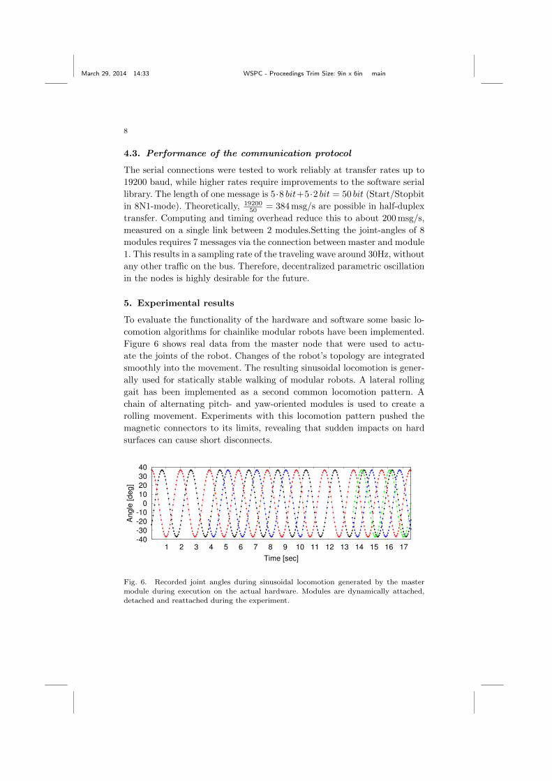
5. Experimental results
To evaluate the functionality of the hardware and software some basic lo-
comotion algorithms for chainlike modular robots have been implemented.
Figure 6 shows real data from the master node that were used to actu-
ate the joints of the robot. Changes of the robot’s topology are integrated
smoothly into the movement. The resulting sinusoidal locomotion is gener-
ally used for statically stable walking of modular robots. A lateral rolling
gait has been implemented as a second common locomotion pattern. A
chain of alternating pitch- and yaw-oriented modules is used to create a
rolling movement. Experiments with this locomotion pattern pushed the
magnetic connectors to its limits, revealing that sudden impacts on hard
surfaces can cause short disconnects.
-40
-30
-20
-10
0
10
20
30
40
1 2 3 4 5 6 7 8 9 10 11 12 13 14 15 16 17
Angle
[deg]
Time [sec]
Fig. 6. Recorded joint angles during sinusoidal locomotion generated by the mastermodule during execution on the actual hardware. Modules are dynamically attached,
detached and reattached during the experiment.
March 29, 2014 14:33 WSPC - Proceedings Trim Size: 9in x 6in main
9
6. Conclusions and future work
This work demonstrates the successful design and creation of a modular
robot by using rapid prototyping with FDM printers and standard compo-
nents. It can be regarded as a case study that shows that the techniques for
designing new robots changed significantly with the increased availability
of 3D-printers. The presented result is a very flexible, open source and low
cost robot platform that is suitable for research and education in the field of
intelligent modular robots. Since every part of the robot is open source, or
at least an easy to purchase standard component, it perfectly fits the needs
of educational purposes or low-cost research. As a first application of the
robotic platform, dynamic detection of the topology has been implemented
in hard- and software.
Future work will focus on improving the bandwidth of the upstream bus,
and the implementation of decentralized motion generation in each module
to reduce communication overhead. The next steps include extensive testing
of various locomotion techniques from literature and integration of different
sensors, to enable adaptive locomotion and intelligent behavior.
References
1. J. Gonzalez-Gomez, A. Valero-Gomez, A. Prieto-Moreno and M. Abderrahim,A new open source 3d-printable mobile robotic platform for education, inProc. of 6th Int. Symposium on Autonomous Minirobots for Research andEdutainment (AMiRE 2011), 2011.
2. H. Zhang, J. Gonzalez-Gomez and J. Zhang, A new application of modularrobots on analysis of caterpillar-like locomotion, in Mechatronics, 2009. ICM2009. IEEE International Conference on, april 2009.
3. S. Hirose and H. Yamada, Snake-like robots [tutorial], Robotics AutomationMagazine, IEEE 16, 88 (march 2009).
4. S. Murata and H. Kurokawa, Self-Organizing Robots, Springer Tracts in Ad-vanced Robotics, Vol. 77 (Springer, 2012).
5. D. Krupke, G. Li, J. Zhang, H. Zhang and H. P. Hildre, Flexible modularrobotic environment for research and education, in 26th European Conferenceon Modelling and Simulation. ECMS2012 , 2012.
6. R. Diankov, Automated construction of robotic manipulation programs, PhDthesis, Robotics Institute, Carnegie Mellon University, (Pittsburgh, PA, 2010).
7. J. Gonzalez-Gomez, Openmr: Modular robots plug-in for openrave http://www.iearobotics.com/wiki/index.php?title=OpenMR:Modular Robots plug-in for Openrave, visited: 2014/01/03.
8. R. Smith, Open dynamics engine http://www.ode.org, visited: 2014/01/03.9. R. Jones, P. Haufe, E. Sells, P. Iravani, V. Olliver, C. Palmer and A. Bowyer,
Reprap - the replicating rapid prototyper, Robotica 29, 177 (2011).