Embed Size (px)
Citation preview

DOI: 10.1021/la902886d 2951Langmuir 2010, 26(4), 2951–2957 Published on Web 12/11/2009
pubs.acs.org/Langmuir
© 2009 American Chemical Society
Print-and-Peel Fabricated Passive Micromixers
Marlon S. Thomas, Joseph M. Clift, Brent Millare, and Valentine I. Vullev*
Department of Bioengineering, University of California, Riverside, California 92521
Received August 4, 2009. Revised Manuscript Received November 17, 2009
Advection driven mixing is essential for microfluidics and poses challenges to the design of microdevices. Forcetransducers or complex channel configurations provide means for, respectively, active or passive disrupting of laminarflows and for homogenizing the composing fluids. Print-and-peel (PAP) is a nonlithographic fabrication technique thatinvolves direct printing of masters for molding polymer components of microdevices. PAP, hence, allows for facile andexpedient preparation of microfluidic devices, without requiring access to specialized microfabrication facilities.We utilized PAP for fabrication of microfluidic devices capable of turning, expanding, and contracting microflows. Weexamined the mixing capabilities of these devices under flow conditions of small Reynolds numbers (0.2-20) and largeP�eclet numbers (260-26 000), under which advection is the dominant mode of mass transfer. We focused on mixingchannels with arched shapes and examined the dependence of the mixing performance on the turns and the expansionsalong the direction of the microflows. Three-dimensional expansion and contraction, along with an increase in themodes of twisting of the laminar currents, improved the quality of mixing. The simplicity in the described fabrication ofthe investigated passive micromixers makes PAP an attractive alternative for expedient device prototyping.
Introduction
This article describes a comparative study of the performanceof nonlithographically fabricated micromixers. Using print-and-peel (PAP) approaches, we fabricated a series of microfluidic( μFL) devices, in which channels with round cross sectionsserved as mixing chambers. We tested the performance of thesePAP-fabricated micromixers at relatively small Reynolds num-bers, Re, ranging between about 0.2 and 20. Expectedly, theaddition of curvatures in the direction of the fluid flows improvedthe mixing performance of the PAP-fabricated devices.
Microfluidics has gained significance as an interdisciplinarytechnology with a broad range of applications in chemistry,biology, and physics.1-14 Laminar flows are prevalent in μFLdevices due to the relatively small Reynolds numbers characteristicof the small cross sections of the channels.15 Such laminar micro-flows have proven immensely beneficial for applications, such as
membraneless fuel cells16-18 and optical waveguiding,7,19,20 whichrequire well-defined interfaces between miscible liquids. For othertypes of microfluidics applications, involving “lab-on-a-chip”analytical and sensing techniques, achieving fast and efficientmixing in submicroliter volumes is imperative.21-26 Fast andefficient mixing in biosensors and bioanalytical microdevices,for example, not only assures speed and quality in the overalldevice performance, but also allows for direct monitoring of thedynamics of chemical and biochemical processes with subsecondresolution.27
Decreasing the cross sections of the channels and slowing downthe fluid flows will allow for diffusion-driven homogenizing ofmiscible liquids at small Reynolds numbers and at small P�ecletnumbers.23,28-30 For small-P�eclet-number conditions, however,relatively long time spans, exceeding the diffusion time constants,are required. For example, the characteristic diffusion times,τD, for 15 kDa globular proteins in aqueous media, are about23 s, 90 s, and 350 s for diffusion lengths, l, of 50 μm, 100 μm, and200 μm, respectively
τD ¼ l2
Dð1Þ
*E-mail: [email protected].(1) Chen, H.; Fan, Z. H. Electrophoresis 2009, 30, 758–765.(2) Abdelgawad, M.; Wheeler, A. R. Adv. Mater. 2009, 21, 920–925.(3) van Noort, D.; Ong, S. M.; Zhang, C.; Zhang, S.; Arooz, T.; Yu, H.
Biotechnol. Prog. 2009, 25, 52–60.(4) Leng, J.; Salmon, J.-B. Lab Chip 2009, 9, 24–34.(5) Sorger, P. K. Nat. Biotechnol. 2008, 26, 1345–1346.(6) Sia, S. K.; Kricka, L. J. Lab Chip 2008, 8, 1982–1983.(7) Psaltis, D.; Quake, S. R.; Yang, C. Nature 2006, 442, 381–386.(8) Paguirigan, A. L.; Beebe, D. J. BioEssays 2008, 30, 811–821.(9) Walker, G. M.; Zeringue, H. C.; Beebe, D. J. Lab Chip 2004, 4, 91–97.(10) Moorthy, J.; Beebe, D. J. Anal. Chem. 2003, 75, 292A–301A.(11) Beebe, D. J.;Mensing, G. A.;Walker, G.M.Annu. Rev. Biomed. Eng. 2002,
4, 261–286.(12) Atencia, J.; Beebe, D. J. Nature 2005, 437, 648–655.(13) Weibel, D. B.; Garstecki, P.;Whitesides, G.M.Curr. Opin. Neurobiol. 2005,
15, 560–567.(14) Mehta, G.; Lee, J.; Cha, W.; Tung, Y.-C.; Linderman, J. J.; Takayama, S.
Anal. Chem. 2009, 81, 3714–3722.(15) Brody, J. P.; Yager, P.; Goldstein, R. E.; Austin, R. H. Biophys. J. 1996, 71,
3430–3441.(16) Abruna, H. D.; Matsumoto, F.; Cohen, J. L.; Jin, J.; Roychowdhury, C.;
Prochaska, M.; van Dover, R. B.; DiSalvo, F. J.; Kiya, Y.; Henderson, J. C.;Hutchison, G. R. Bull. Chem. Soc. Jpn. 2007, 80, 1843–1855.(17) Ferrigno, R.; Stroock, A. D.; Clark, T. D.; Mayer, M.; Whitesides, G. M.
J. Am. Chem. Soc. 2002, 124, 12930–12931.(18) Jayashree, R. S.; Gancs, L.; Choban, E. R.; Primak, A.; Natarajan, D.;
Markoski, L. J.; Kenis, P. J. A. J. Am. Chem. Soc. 2005, 127, 16758–16759.
(19) Vezenov, D. V.; Mayers, B. T.; Conroy, R. S.; Whitesides, G. M.; Snee,P. T.; Chan, Y.; Nocera, D. G.; Bawendi, M. G. J. Am. Chem. Soc. 2005, 127,8952–8953.
(20) Mayers, B. T.; Vezenov, D. V.; Vullev, V. I.; Whitesides, G.M.Anal. Chem.2005, 77, 1310–1316.
(21) Stone, H. A.; Stroock, A. D.; Ajdari, A. Ann. Rev. Fluid Mech. 2004, 36,381–411.
(22) Hessel, V.; Loewe, H.; Schoenfeld, F. Chem. Eng. Sci. 2005, 60, 2479–2501.(23) Locascio, L. E. Anal. Bioanal. Chem. 2004, 379, 325–327.(24) Ottino, J. M.; Wiggins, S. Science 2004, 305, 485–486.(25) Campbell, C. J.; Grzybowski, B. A. Philos. Trans., Ser. A 2004, 362, 1069–
1086.(26) Stroock, A. D.; Dertinger, S. K. W.; Ajdari, A.; Mezit, I.; Stone, H. A.;
Whitesides, G. M. Science 2002, 295, 647–651.(27) Song, H.; Chen, D. L.; Ismagilov, R. F. Angew. Chem., Int. Ed, 2006, 45,
7336–7356.(28) The P�eclet number represents the ratio between the advection and diffusion
contributions to mass transfer.(29) Nauman, E. B.; Nigam, A. Chem. Eng. Technol. 2004, 27, 293–296.(30) Hattori, K.; Sugiura, S.; Kanamori, T. Lab Chip 2009, 9, 1763–1772.

2952 DOI: 10.1021/la902886d Langmuir 2010, 26(4), 2951–2957
Article Thomas et al.
where D is the diffusion coefficient, and for lysozyme (MW =14.5 kDa) and myoglobin (MW = 16.9 kDa) in aqueous media,D = 1.1 � 10-6 cm2 s-1.31
The long time periods, along with the relatively small amountsof material that can be processed, make diffusion-dominatedmixing impractical for a large number of microfluidic applica-tions. Introducing advection to low-Reynolds-number micro-flows, on the other hand, significantly accelerates their mixing.
Advection-dominated mixing at low Reynolds numbers and athigh P�eclet numbers, therefore, is essential for μFL devices.Folding currents with miscible liquids within one another de-creases the diffusion lengths and, hence, considerably decreasesthe characteristic diffusion times. Inmicrodevices, such effects areachieved via incorporating active or passive micromixers ascomponents of the devices. Active micromixers employ externaloscillating forces for disturbing the laminar flows,25,32-34 whilepassive micromixers rely on complex channel geometries toachieve the desired advection.22,26,35 Chaotic micromixers com-prising asymmetric “herringbone”-shaped grooves on the floorsof microchannels, for example, provide complete mixing at smallReynolds and large P�eclet numbers, e.g., Re < 100 and Pe =20000.26 Utilizing droplets, introduced in microchannels as“plugs” of immiscible fluids with volumes of femtoliters tomicroliters, presents an alternative for achieving millisecond-mixing times via advection and short diffusion length scales.24,27
The complexity of such passive micromixers, however, placeschallenging requirements on their fabrication, which often in-volves multistep procedures.
Recently, we demonstrated the utility of print-and-peelfor fabrication of μFL sensors.36-38 Computer-aided design(CAD) patterns were directly printed onto smooth substrates toproduce masters with positive relief features of two-dimensional(2D) channel configurations. Placing three-dimensional (3D)elements on printed masters, allowed us to fabricate curvedoff-plane channels that acted as mixers in continuous-flow μFLsensors in a single polymer-molding step (see SupportingInformation).36-38 This PAP nonlithographic methodologyoffers simplicity and expedience in prototypingmicrodevices withvarious complexities.36-41
Khine et al. further explored PAP41-43 and fabricatedmicromixers that performed efficiently at Reynolds numbersbetween 10 and 55.43 No 3D elements were employed, how-ever, and the fabrication involved preparing four polymerslabs and stacking them over one another with precisealignment.43
By employing solely 3D elements, without CAD patterns,Ghatak et al. demonstrated the fabrication of complexpatterns of channels within polymer slabs.44-47 Using thisapproach, they fabricated in a single molding step micro-channels with round cross sections and with helical groovesalong the channel walls.44,45 This channel geometry forcedadvection currents and mixing at a wide range of Reynoldsnumbers.45
Asmentioned above, PAP allowed us to fabricate a μFL sensorequipped with two inlet channels:36 (1) a reagent inlet channel fora continuous flow of a luminogenic indicator solution and (2) athin injection channel throughwhich small volumes of analyte areintroduced. Through a relatively wide channel, following themerging of the reagent and injection channels, the laminar flowwas carried into an arched mixing chamber/channel prior toemission detection.36We showed themixing performance of thesedevices under pulsatile regime; i.e., we injected small volumes ofcolored aqueous solution (e.g., 1 to 40 μL) and observed itshomogenization with water continuously flowing through thereagent inlet channel.36
Employing a series of PAP-fabricated μFL devices, herein, wetested the features that govern the efficiency of the PAP-fabricatedoff-plane arched micromixers.36,38 Our findings revealed that, inaddition to the geometry of the micromixers, the direction ofintroducing the laminar flows into the mixers plays a crucial rolefor the quality of mixing.
Results and Discussion
PAP Fabrication. Using a solid-ink printer,37,40,48 the CADpatterns were printed on overhead transparency films to producepositive-relief features of 2D channel networks. To completethe masters for molding the polymer components of the devices,onto the printed features we adhered 3D elements that formedthe mixing arched channel as well as the inlet and outlet connect-ing channels. We cast polydimethylsiloxane (PDMS) over themasters. Having allowed the elastomer to cure, we removed itfrom the printouts and pulled the 3D elements from the bulk ofthe PDMS slabs to produce the polymer components of thedevices. Following oxygen-plasma activation of the surfaces ofthe device components,49 we permanently attached the PDMSslabs to glass slides to complete the microdevices (see SupportingInformation).
As we and others have demonstrated, solid ink printersreproduce smoother features in comparison with the LaserJetswith compatible resolution.36-38,40,48 The channels from theCAD-printed features had large aspect ratios: they were about10 to 15 μm high and more than 250 μm wide.38
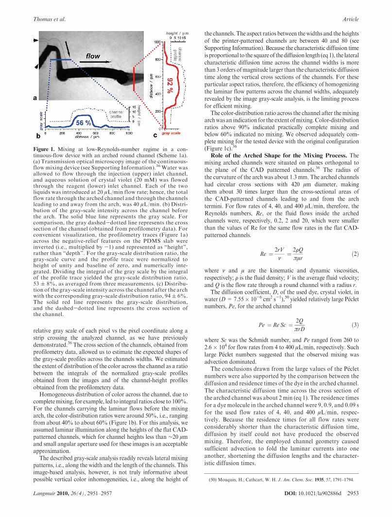
Mixing. We examined the mixing performance of the devicesunder continuous-flow conditions. Colored and colorless aqu-eous solutions were allowed to continuously flow through bothinlet channels. Before entering the mixing arched channel, thecolored and colorless liquids were clearly separated in a laminarfashion, after the arch, the color was distributed across thechannel width (Figure 1a).
Gray-scale analysis of the image revealed near completemixing for flow rates from 4 to 400 μL/min. We plotted the
(31) Liu, M.-K.; Li, P.; Giddings, J. C. Protein Sci. 1993, 2, 1520–1531.(32) Ryu, K. S.; Shaikh, K.; Goluch, E.; Fan, Z.; Liu, C. Lab Chip 2004, 4,
608–613.(33) Liu, R. H.; Yang, J.; Pindera,M. Z.; Athavale,M.; Grodzinski, P.Lab Chip
2002, 2, 151–157.(34) Oddy, M. H.; Santiago, J. G.; Mikkelsen, J. C.Anal. Chem. 2001, 73, 5822–
5832.(35) Villermaux, E.; Stroock, A. D.; Stone, H. A. Phys. Rev. E 2008, 77, 015301.(36) Vullev, V. I.; Wan, J.; Heinrich, V.; Landsman, P.; Bower, P. E.; Xia, B.;
Millare, B.; Jones, G., II J. Am. Chem. Soc. 2006, 128, 16062–16072.(37) Hong, C.; Bao, D.; Thomas,M. S.; Clift, J.M.; Vullev, V. I.Langmuir 2008,
24, 8439–8442.(38) Thomas, M. S.; Millare, B.; Clift, J. M.; Bao, D.; Hong, C.; Vullev, V. I.
Ann. Biomed. Eng., in press.(39) Coltro, W. K. T.; Piccin, E.; Fracassi da Silva, J. A.; Lucio do Lago, C.;
Carrilho, E. Lab Chip 2007, 7, 931–934.(40) Kaigala, G. V.; Ho, S.; Penterman, R.; Backhouse, C. J. Lab Chip 2007, 7,
384–387.(41) Chen, C.-S.; Breslauer, D. N.; Luna, J. I.; Grimes, A.; Chin, W.-c.; Lee, L.
P.; Khine, M. Lab Chip 2008, 8, 622–624.(42) Grimes, A.; Breslauer, D. N.; Long, M.; Pegan, J.; Lee, L. P.; Khine, M.
Lab Chip 2008, 8, 170–172.(43) Long, M.; Sprague, M. A.; Grimes, A. A.; Rich, B. D.; Khine, M. Appl.
Phys. Lett. 2009, 94, 133501/133501–133501/133503.
(44) Verma, M. K. S.; Majumder, A.; Ghatak, A. Langmuir 2006, 22, 10291–10295.
(45) Verma, M. K. S.; Ganneboyina, S. R.; Rakshith, R, V.; Ghatak, A.Langmuir 2008, 24, 2248–2251.
(46) Majumder, A.; Ghatak, A.; Sharma, A. Science 2007, 318, 258–261.(47) Arul, E. P.; Ghatak, A. Langmuir 2009, 25, 611–617.(48) Wang, W.; Zhao, S.; Pan, T. Lab Chip 2009, 9, 1133–1137.(49) Millare, B.; Thomas,M.; Ferreira, A.; Xu, H.; Holesinger, M.; Vullev, V. I.
Langmuir 2008, 24, 13218–13224.
DOI: 10.1021/la902886d 2953Langmuir 2010, 26(4), 2951–2957
Thomas et al. Article
relative gray scale of each pixel vs the pixel coordinate along astrip crossing the analyzed channel, as we have previouslydemonstrated.36 The cross section of the channels, obtained fromprofilometry data, allowed us to estimate the expected shapes ofthe gray-scale profiles across the channels widths. We estimatedthe extent of distribution of the color across the channel as a ratiobetween the integrals of the normalized gray-scale profilesobtained from the images and of the channel-height profilesobtained from the profilometery data.
Homogeneous distribution of color across the channel, due tocompletemixing, for example, led to integral ratios close to 100%.For the channels carrying the laminar flows before the mixingarch, the color-distribution ratios were around 50%, i.e., rangingfrom about 40% to about 60% (Figure 1b). For this analysis, weassumed laminar illumination along the heights of the flat CAD-patterned channels, which for channel heights less than ∼20 μmand small angular aperture used for these images is an acceptableapproximation.
The described gray-scale analysis readily reveals lateral mixingpatterns, i.e., along the width and the length of the channels. Thisimage-based analysis, however, is not truly informative aboutpossible vertical color inhomogeneities, i.e., along the height of
the channels. The aspect ratios between thewidths and the heightsof the printer-patterned channels are between 40 and 80 (seeSupporting Information). Because the characteristic diffusion timeis proportional to the squareof thediffusion length (eq1), the lateralcharacteristic diffusion time across the channel widths is morethan 3 orders ofmagnitude larger than the characteristic diffusiontime along the vertical cross sections of the channels. For theseparticular aspect ratios, therefore, the efficiency of homogenizingthe laminar flow patterns across the channel widths, adequatelyrevealed by the image gray-scale analysis, is the limiting processfor efficient mixing.
The color-distribution ratio across the channel after the mixingarchwas an indication for the extent ofmixing.Color-distributionratios above 90% indicated practically complete mixing andbelow 60% indicated no mixing. We observed adequately com-plete mixing for the tested device with the original configuration(Figure 1c).36
Role of the Arched Shape for the Mixing Process. Themixing arched channels were situated on planes orthogonal tothe plane of the CAD patterned channels.36 The radius ofthe curvature of the arch was about 1.3 mm. The arched channelshad circular cross sections with 420 μm diameter, makingthem about 30 times larger than the cross-sectional areas ofthe CAD-patterned channels leading to and from the archtermini. For flow rates of 4, 40, and 400 μL/min, therefore, theReynolds numbers, Re, or the fluid flows inside the archedchannels were, respectively, 0.2, 2 and 20, which were smallerthan the values of Re for the same flow rates in the flat CAD-patterned channels.
Re ¼ 2rV
ν¼ 2FQ
πμrð2Þ
where ν and μ are the kinematic and dynamic viscosities,respectively; F is the fluid density; V is the average fluid velocity;and Q is the flow rate through a round channel with a radius r.
The diffusion coefficient, D, of the used dye, crystal violet, inwater (D=7.55� 10-6 cm2 s-1),50 yielded relatively large P�ecletnumbers, Pe, for the arched channel
Pe ¼ Re Sc ¼ 2Q
πrDð3Þ
where Sc was the Schmidt number, and Pe ranged from 260 to2.6 � 104 for flow rates from 4 to 400 μL/min, respectively. Suchlarge P�eclet numbers suggested that the observed mixing wasadvection dominated.
The conclusions drawn from the large values of the P�ecletnumbers were also supported by the comparison between thediffusion and residence times of the dye in the arched channel.The characteristic diffusion time across the cross section ofthe arched channel was about 2min (eq 1). The residence timesfor a dye molecule in the arched channel were 9, 0.9, and 0.09 sfor the used flow rates of 4, 40, and 400 μL/min, respec-tively. Because the residence times for all flow rates wereconsiderably shorter than the characteristic diffusion time,diffusion by itself could not have produced the observedmixing. Therefore, the employed channel geometry causedsufficient advection to fold the laminar currents into oneanother, shortening the diffusion lengths and the character-istic diffusion times.
Figure 1. Mixing at low-Reynolds-number regime in a con-tinuous-flow device with an arched round channel (Scheme 1a).(a) Transmission optical microscopy image of the continuous-flow mixing device (see Supporting Information).36 Water wasallowed to flow through the injection (upper) inlet channel,and aqueous solution of crystal violet (20 mM) was flowedthrough the reagent (lower) inlet channel. Each of the twoliquids was introduced at 20 μL/min flow rate; hence, the totalflow rate through the arched channel and through the channelsleading to and away from the arch, was 40 μL/min. (b) Distri-bution of the gray-scale intensity across the channel beforethe arch. The solid blue line represents the gray scale. Forcomparison, the gray dashed-dotted line represents the crosssection of the channel (obtained from profilometry data). Forconvenient visualization, the profilometry traces (Figure 1a)across the negative-relief features on the PDMS slab wereinverted (i.e., multiplied by -1) and represented as “height”,rather than “depth”. For the gray-scale distribution ratio, thegray-scale curve and the profile trace were normalized toheight of unity and baseline of zero, and numerically inte-grated. Dividing the integral of the gray scale by the integralof the profile trace yielded the gray-scale distribution ratio,53 ( 8%, as averaged from three measurements. (c) Distribu-tion of the gray-scale intensity across the channel after the archwith the corresponding gray-scale distribution ratio, 94( 6%.The solid red line represents the gray-scale distribution,and the dashed-dotted line represents the cross section ofthe channel.
(50) Mouquin, H.; Cathcart, W. H. J. Am. Chem. Soc. 1935, 57, 1791–1794.

2954 DOI: 10.1021/la902886d Langmuir 2010, 26(4), 2951–2957
Article Thomas et al.
The Dean number, κ, representing the ratio between viscousand centrifugal forces acting on curved fluid flows51-57
K ¼ Re
ffiffiffiffir
R
rð4Þ
where R is the radius of the arch, and r is the radius of the crosssection of the arched channel.57
The values of the Dean number ranged between 0.08 and 8 forthe employed flow rates through the arched channels with 1.3mmradius of the arch. Such small values of κ for 4 and 40 μL/minsuggested that the origin of the mixing at these flow rates was notsecondary fluid currents caused by centrifugal forces resultantfrom the curved direction of the flows traveling along the archedchannel.
We examined the contribution of the arched geometry bytesting the mixing by a device, in which the round-cross-sectionchannel with identical dimensions was straight, rather thanarched (Figure 2). When we used a straight large-cross-sectionchannel, situated onto the plane of the CAD-patterned channels,the quality of mixing deteriorated (Figure 2d). The lack of mixingwas especially pronounced at the intermediate flow rate we used,i.e., at 40 μL/min. It should be noted, however, that at 40 μL/minthe boundary line between the colored and colorless currentsshifted toward the colorless solution (Figure 2c,d), i.e., toward theexterior of the sharp right-angle turn that the fluids undertookentering the wide channel (Scheme 1b).
Figure 2. Performance of a device with a straight channel, instead of an arch (Scheme 1b). (a) Transmission optical microscopy image of thedevice.Water and aqueous solution of crystal violet (20mM)were allowed to flow, respectively, through the reagent (lower) and the injection(upper) inlet channel. Each of the two liquids was introduced at 200 μL/min flow rate; hence, the total flow rate through the device aftermerging the two flows was 400 μL/min. (b) Schematic representation of the side view of the device straight and exit channels. (c) Distributionof the gray-scale intensity across the channel before entering the large-cross-section channel for different flow rates, with the correspondinggray-scale distribution ratios (error between 5%and8%). (d)Distributionof the gray-scale intensity across the channel after exiting the large-cross-section channel for different flow rates, with the corresponding gray-scale distribution ratios (error between 7% and 12%). Thedashed-dotted gray lines in (c) and (d) represent the channel boundaries.
(51) Berger, S. A.; Talbot, L.; Yao, L.-S. Ann. Rev. Fluid Mech. 1983, 15, 461–512.(52) Verkaik, A. C.; Beulen, B. W. A. M. M.; Bogaerds, A. C. B.; Rutten, M. C.
M.; van de Vosse, F. N. Phys. Fluids 2009, 21, 023602/023601–023602/023613.(53) Mouza, A. A.; Patsa, C. M.; Sch€onfeld, F. Chem. Eng. Res. Des. 2008, 86,
1128–1134.(54) Sch€onfeld, F.; Hessel, V.; Hofmann, C. Lab Chip 2004, 4, 65–69.(55) Kim, S.; Lee, S. J. Exp. Fluids 2009, 46, 255–264.(56) Jiang, F.; Drese, K. S.; Hardt, S.; K€upper,M.; Sch€onfeld, F.AIChE J. 2004,
50, 2297–2305.(57) The Dean number has also been defined as K= 21/2 κ, and as K= κ2 / 2. In
eq 4, for example, the diameter, d, instead the radius, r, of the channel has been used.

DOI: 10.1021/la902886d 2955Langmuir 2010, 26(4), 2951–2957
Thomas et al. Article
An increase in the flow rate to 400 μL/min further increased theshift of the boundary line between the colored and colorlesscurrent (Figure 2c,d). For 4 μL/min, on the other hand, thegray color was gradually distributed into the “colorless side” ofthe channel (Figure 2c,d).
By itself, the right-angle turn of the flow upon entering into thewide channel was not sufficient for the observed partial mixingat the investigated flow rates (Figure 2). For devices with the same
CAD-patterned geometry, but nowide channel added, we did notobserve even partial mixing at 4 to 400 μL/min (Figure 3b).Furthermore, two-dimensional expansion of the fluid onlywithin the CAD plane did not cause any mixing (Figure 3c,d).These findings demonstrate the importance of the rapid three-dimensional expansion of the fluid for creating chaotic advectionessential for efficient mixing.
The radius of the arch curvature was, indeed, too large toexpect chaotic advection resultant from the turn of the flowsthrough the arched channel. The difference in the mixingresults for the arched and the straight channel (Figures 1and 2), however, indicated that the quality of mixing dependedon the direction of the flow after expending into the wide,round channels. While for the straight channel (Figure 2) theoverall flow direction was along the CAD plane of the device,for the arched channel (Figure 1) the liquid flowed 90�“upward” off the plane, turned in the arch, and flowed backto the same plane to take another sharp right-angle turn to exitthe arched channel. Apparently, these three turns in the flow,and hence the arched geometry of the channel, were key forefficient mixing.Direction of Entering the Arched Channel. The laminar
flows entered the arched channel perpendicular to the plane of thearch and turned 90� “upward” (Scheme 1a). Therefore, theboundary plane, separating the laminar flows, was perpendicularto the plane of the arch. Should incompletely mixed liquidremained, the plane separating these unmixed currents wouldbe orthogonal to the CAD-patterned plane of the deviceand orthogonal to the plane of the arch (Scheme 1a). The liquidflowing “downward” from the arch would sharply turn intothe 10-μm-high exit channel. The boundary plane, separatingthe laminar currents, would be parallel to the floor of the high-aspect-ratio exit channel, forcing the remaining unmixed liquid
Scheme 1. Direction of Flows through Devices with Different
Configuration
Figure 3. Transmission optical microscopic images of devices comprising solely flat CAD-patterned channels. The images show the flowpatterns through the devices at different flow rates. (a,b) Device with the geometry of the continuous-flow μFL sensor (see SupportingInformation),36 in which the mixing arch was replaced with CAD-patterned flat channel. Water and aqueous solution of crystal violet(20 mM) were introduced through, respectively, the reagent (lower) and the injection (upper) inlet channel at combined flow rates of(a) 4 μL/min, and (b) 400 μL/min. The Reynolds numbers for these channels were about an order of magnitude smaller than the Reynoldsnumbers for the large-cross-section channels (Figure 2, Scheme 1b) for the same flow rates. (c,d) Y-junction device (see SupportingInformation), in which the arched channels was replacedwith a CAD-patterned circle.Water and aqueous solution of crystal violet (20mM)were flowed through, respectively, the upper and the lower inlet channel of the Y junction to form two-component laminar currents withcombined flow rates of (c) 4 μL/min and (d) 400 μL/min. For improved visualization, the borders of the channels, filled with the colorlessliquid, are outlined with gray dotted lines.

2956 DOI: 10.1021/la902886d Langmuir 2010, 26(4), 2951–2957
Article Thomas et al.
currents to fold over one another within the confined channelheight.
In contrast, for the straight channel (Figure 2, Scheme 1b), theboundary plane between the colored and colorless laminarlyflowing liquids did not turn or twist. The boundary planeremained parallel to the direction of the exiting channel andperpendicular to the CAD-patterned plane of the device(Scheme 1b). Therefore, forcing the flow into the small-heightexit channel would cause folding of liquids only of the same colorintoone another.Overall, such liquid current patternswould yieldincompletemixing, whichwas consistent with the observed results(Figure 2).
To examine the merit of this somewhat simplified view of thecontribution of the direction of the current turns to the quality ofmixing, we fabricated and tested devices in which the entry andexit channels lay on the same line. The flow in such a device alsoexperienced a sharp right-angle turn “upward”, followed by acurved turn of the arched channel, and another sharp right-angleturn toward the exit channel. Unlike in the original setup(Scheme 1a), however, the boundary plane between the lami-nar-flowing colored and colorless liquids remained parallel to theplane of the arch and orthogonal to the CAD-patterned plane ofthe device (Scheme 1c).
The performance of such Y-junction devices with smooth,arched channels revealed partial mixing at 40 and 400 μL/min(Figure 4). The presence of partial mixing and the lack of a well-defined boundary line between the colored and colorless solutionsin the channel after the arch suggested advection processes foldingthe laminar currents into one another as the fluid passed in,through, and out of the arched channel. This contrast with theresults from the device with a straight channel (Figure 2) furtherdemonstrated the importance of the arched geometry for themixing process.
A comparison between the performance of the original device(Figure 1)36 and the Y-junction device (Figure 4) revealed inferiormixing when the entry and exit channels were along the same line(Figures 1c and 4b). Therefore, the direction at which the laminarflows entered the archedmixing channels was determinant for theextent of observed mixing.Importance of Twists and Turns. Our findings showed
the key importance of the manner in which the laminar flowswere turned so that the boundary planes, separating thelaminarly moving liquids, were twisted to cause foldingof currents and decreasing of the diffusion lengths. Wedemonstrated that the original device configuration providesefficient mixing under continuous-flow conditions due to(1) the arched shape of mixing channel, (2) the expandedcross-section of the mixing channel, and (3) the directionof introducing the laminar flow into the mixing channel(Figure 1, Scheme 1a).
The performance of universally applicable micromixers, how-ever, should not depend on the exact device configuration and onthe direction of the inflow. To decouple the quality of perfor-mance from the direction of the laminar inflows, we exploredadditional advection modes within the mixing arch. Helicalgrooves along the walls of the arched channels (Figure 5b)allowed us to introduce an alternative mode of twisting of theliquid flows in the mixing channels.
Arch-channel mixers with helical grooves along their wallsinstalled in Y-junction devices resulted in complete mixing forall tested flow rates (Figure 5c). In comparison with thesmooth arched channels (Figure 4), the arch with helicalgrooves produced superior mixing for the tested flow rates(Figure 5c).
The helical grooves along the walls of the mixing channels addan additional curvature in the direction of the flow. As defined ineq 4, κ cannot exceed Re. Although the addition of the spiralgrooves allows for maximizing the Dean number for the em-ployed flow conditions, the values for κ are still relatively smalldue to the small values of Re. Furthermore, the Dean numberprovides dimensionless evaluation of two-dimensional flows, andits application to three-dimensional flow geometries, i.e., an archof a helix, is not necessarily an appropriate approximation.In fact, Ghatak et al. observed efficient mixing in helical channelsat apparent Dean numbers smaller than ∼10,45 which is inagreement with our findings. Apparently, the shear between thelaminar flows twisted in the helically grooved, arched channelsprovides the advection essential for efficient mixing.
Dimensionless flow characteristics, such as Dean number(eq 4), indeed, provide guidance for optimizing the design ofmicromixers.53-56 For flow conditions at relatively small Dean
Figure 4. Performance of a Y-junction device comprising anarched channel with circular cross section (Scheme 1c). (a) Trans-mission optical microscopy image of the arched section of thedevice (see Supporting Information). Laminar currents of waterand aqueous solution of crystal violet (20 mM) are flowed into thearch at 400 μL/min flow rate. (b) Distribution of the gray-scaleintensity across the channel before (blue dotted lines) and after (redsolid lines) the arch (at different flow rates) with the correspondinggray-scale distribution ratios (error between 4% and 8%). Thedashed-dotted gray lines represent the channel boundaries.

DOI: 10.1021/la902886d 2957Langmuir 2010, 26(4), 2951–2957
Thomas et al. Article
numbers, however, we observed mixing comparable with themixing from, for example, meandering microdevices at inter-mediate and high κ.53,56 Therefore, such dimensionless analysis
cannot encompass all the processes responsible for themixing thatwe observed for these PAP-fabricated devices.
TheDean numbers we calculated are descriptive of the flowsmoving through the arched channels and not of the flows at thepoints of entry and exit of the arch. Furthermore, the arch-of-a-helix geometry (Figure 5b) adds another level of com-plexity that presents a challenge for analysis using solelydimensionless quantities. Regardless of the small apparentDean numbers, our findings confirm that the irregularities,involving twists, sharp turns, and expansions and contractionsof the flows, prevalently provide the advection essential forfast and complete mixing at small Reynolds and large P�ecletnumbers.
Conclusions
Print-and-peel (PAP) allowed us to expediently and facilelyfabricate a range of microfluidic device with potential mixingcapabilities. The tested geometries of the arched channels pro-vided not only turns in the flow direction, but also expansion andcontraction of the liquid currents at the entry and the exit of thearch. Such flow geometries proved essential for achieving efficientmixing. Additional flow twists, caused by helically groovedchannel walls, resulted into close-to-ideally complete mixing.Mixing at low Reynolds numbers and large P�eclet numbers isan important design challenge for microfluidic devices. PAP hasthe potential formaking suchdesigns achievablewithout access tospecialized microfabrication facilities.
Acknowledgment. This work was supported by the U.S.Department of Education and the U. C. Regents FacultyDevelopment Award. We extend our gratitude to Prof. VictorG. J. Rodgers for the helpful discussions on the mass-transportphenomena.
Supporting Information Available: Experimental details.This material is available free of charge via the Internet athttp://pubs.acs.org.
Figure 5. Performance of a Y-junction device comprising a round,arched channel with helical grooves along the walls. Transmissionoptical microscopy images of (a) a section of an arched channel withsmooth walls and (b) a section of an arched channel with fourgrooves helically winding along the circular wall. (c) Distributionof the gray-scale intensity across the channel after the arch withgrooved walls. The solid red lines represent the gray-scale intensityacross the channel with the corresponding gray-scale distributionratios (at different flow rates; error less than 5%), and the dottedgray line represents the cross section of the channel (from profilo-metry data).


![JHEP06(2015)1163A10.1007... · 3 Event reconstruction Events are reconstructed with the CMS particle-flow algorithm [44,45]. Using an opti-mized combination of information from the](https://img.pdfslide.us/doc/110x75/5e7e945b79fc8840b16b5a43/jhep062015116-3a101007-3-event-reconstruction-events-are-reconstructed-with.jpg)


![Applied Surface Science - qcc.tyut.edu.cnqcc.tyut.edu.cn/__local/F/D6/55/8EB5BEF159B386D87C04E20D594_97C2FA8C_… · synthesizedinanataseTiO2 crystal[44,45].Photocatalysis of CH3OH](https://img.pdfslide.us/doc/110x75/5e6b65fc669a555fa03a7483/applied-surface-science-qcctyuteducnqcctyuteducnlocalfd6558eb5bef159b386d87c04e20d59497c2fa8c.jpg)

![arXiv:0804.2788v2 [cond-mat.dis-nn] 18 Jul 2008 · RG language), and to the irrelevant operators.44,45 In particular, we expect scaling correc- tions associated with the leading irrelevant](https://img.pdfslide.us/doc/110x75/5e0aed88b3f8f253b21c8c27/arxiv08042788v2-cond-matdis-nn-18-jul-2008-rg-language-and-to-the-irrelevant.jpg)

![Point-Set Anchors for Object Detection, Instance ... · cluding center points [40,48], corner points [22,14], extreme points [49], octagon points [34], point sets [44,45], and radial](https://img.pdfslide.us/doc/110x75/609e4f7e38c06c16cb22a597/point-set-anchors-for-object-detection-instance-cluding-center-points-4048.jpg)