Embed Size (px)
Citation preview
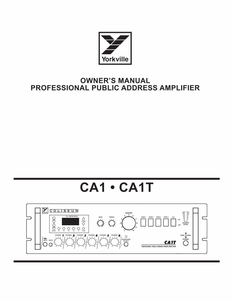
Owner’s Manual PrOfessiOnal Public address aMPlifier
CA1TPROFESSIONAL PUBLIC ADDRESS POWER AMPLIFIER
CHANNEL 1 CHANNEL 2 CHANNEL 3 CHANNEL 4 CHANNEL 5 CHANNEL 6HEADPHONE
OUTPUT
BASS TREBLE
MASTER
ZONE 1 ZONE 2 ZONE 3 ZONE 4 ALL
MUTEINPUTPOWER
Peak / Limiter
ON
OFF
OUTPUTLEVEL
C O L I S E U M
10
9
82
1
73
0
654
10
9
82
1
73
0
654
10
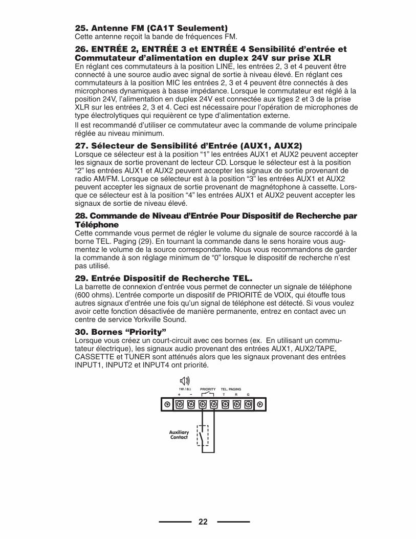
9
82
1
73
0
654
10
9
82
1
73
0
654
10
9
82
1
73
0
654
10
9
82
1
73
0
654
10982
1
73
0
654
10982
1
73
0
654
10
9
82
1
73
0
65
4PLL AM/FM RADIO
M5 M4 M3 M2 M1 POWER
VOLUME
AM/FM
UP
DOWN
MEMORY
CA1 • CA1T
IMPORTANT NOTES• Beforeconnectingandusingthisamplifier,carefullyreadthe
instructionscontainedinthismanual.Pleasesaveforfuturereference.
•Thismanualisimportanttotheoperationofthisproductandmustaccompanyitwhenchangingowners.Thiswillallowthenewownertogetfamiliarwiththeproductforinstallation,operationandsafety.
• FaultyinstallationofthisapparatusfreesYorkvilleSoundofallresponsibility.
CAUTION Topreventtheriskoffireorelectricshock,donotexposethisequipmenttorainordampness.
SAFETY PRECAUTIONS1.Pleasereadthenotesproceededbythesymbol withspe-
cialattention,theyprovideimportantsafetyinformation.2.Thepowersupplyvoltageoftheamplifierhasasufficiently
highvaluetoinvolvetheriskofelectricalshock;therefore,neverinstall,connect,ordisconnecttheequipmentwiththepowersupplyturnedon.
3.Themetalpartsofthisequipmentareearthedbymeansofthepowercable.Ifthepowersocketusedtosupplypowerdoesnothaveanearthconnection,callaqualifiedelectricianwhowillearththeequipmentbymeansoftheterminal.
4.Makesurethatthepowersupplycableoftheequipmentcan-notbetroddenon,orcrushedbyobjectstoensurethatthecableisnotdamaged.
5.Topreventtheriskofelectricshock,neveropentheequipment:therearenopartsinsidethattheusercanuse.
6.Makesurethatnoobjectsorliquidscangetintothespeaker,asthiscouldcauseashortcircuit.
7.Neverattempttomakeanyrepairsthatarenotdescribedinthismanual.Contactyourauthorizedservicecenterorquali-fiedpersonnelwhen:•Theequipmentdoesnotfunction(orfunctionsinananoma-lousway).
•Thepowersupplycablehasbeenseriouslydamaged.
•Objectsorliquidshavegotintotheequipment.
•Theequipmenthasbeensubjecttoheavyimpact.
8.Iftheequipmentisnottobeusedforlongperiodsoftime,switchitoffanddisconnectthepowersupplycable.
9.Iftheequipmentgivesoffanystrangeodorsorsmokeswitchitoffimmediatelyanddisconnectthepowerfromthesupplycable.
PRECAUTIONS• Donotobstructtheventilationgrillesoftheequipment.•Avoidhavingtheamplifierworkonoverloadforalongperiod
oftime.• Fullytightenthescrewterminalsinordertoensuresafe
contact.• Donotforcebuttons,controlsetc.,whentryingtousethem.• Whencleaningexternalparts,donotusethinners,spirits,or
anyothervolatilesubstances.
NOTES IMPORTANT • Avantdebrancheretd’utilisercetamplificateur,lisez
soigneusementlesinstructionscontenuesdanscemanuelVeuillezconserverpourréférencesfutures.
•Cemanuelestimportantpourl’opérationdeceproduitetdoitl’accompagnerlorsqueleproduitchangedepropriétaire.Cecipermettraaunouveaupropriétairedesefamiliariseravecleproduitpourl’installation,l’opérationetlasûreté.
• L’installationinadéquatedecetappareillibèreYorkvilleSounddetouteresponsabilité.
ATTENTION Pourprévenirlerisquedufeuoudedéchargeélectrique,n’exposezpascetéquipementàlapluieouàl’humidité.
PRÉCAUTIONS DE SÛRETÉ1.Veuillezlirelesnotesquisontprécédéparlesymbole
avecuneattentionparticulière,ellesfournis-sentdesinfor-mationsimportantesdesûreté.
2.Latensiond’alimentationdel’amplificateurestsuffisammentélevéepourimpliquerlerisquedechocélectrique;doncnejamaisinstallez,branchezoudébranchezl’équipementlorsquesonblocd’alimentationestallumé
3.Lespiècesenmétaldecetéquipementsontmisesàlaterreàl’aideducordond’alimentation.Silaprisedebranchementutiliséepourfournirl’alimentationn’estpaséquipéed’unraccordementàlamasse,contactezunélectricienqualifiéquiferalenécessairepourassurerquel’équipementestbienraccordéàlamasse.
4.Assurez-vousquelecordond’alimentationdel’équipementnepeutpasêtremarchédessus,ouêtreécrasépardesobjetspourprévenirl’endommagementducordon.
5.Pourempêcherlerisquededéchargeélectrique,n’ouvrezjamaisl’équipement:iln’yal’intérieuraucunepiècesquel’utilisateurnepeutemployer
6.Assurez-vousqu’aucunobjetouliquidenepeutentrerdanslehaut-parleur,carcecipourraitcauseruncourt-circuit.
7.N’essayezjamaisdeprocéderàdesdépannagesquinesontpasdécritsdanscemanuel.Contac-tezvotrecentredeserviceautoriséoupersonnelqualifiélorsque:
•L’appareilnefonctionnepas(oufonctionneanormalement). •Lecordond’alimentationaétésérieusementendommagé. •Objetsouliquidesontpénétréàl’intérieurdel’appareil. •L’équipementaétésujetàl’impactimportant.8.Sivousprévoyeznepasutiliserl’appareilpourunelongue
périodedetemps,éteignezleetdéconnectezlecordond’alimentation.
9.Sil’équipementdégageuneodeurinhabituelleousiilémetdelafuméeéteignezleimmédiate-mentetdéconnectezl’alimentationducordond’alimentation.
PRÉCAUTIONS• N’obstruezpaslesgrillesdeventilationdel’équipement.•évitezdefairetravaillerl’amplificateurensurchargepourde
longuepériodesdetemps.• Serrezcomplètementlesvissesdesterminauxpourassurer
uncontactsûr.• Neforcezpaslesboutons,lescommandesetc.,enessayant
delesemployer.• Ennettoyantlespiècesexternes,n’employezlesdiluants,
lesspiritueux,ouaucuneautresubs-tancevolatile.
3
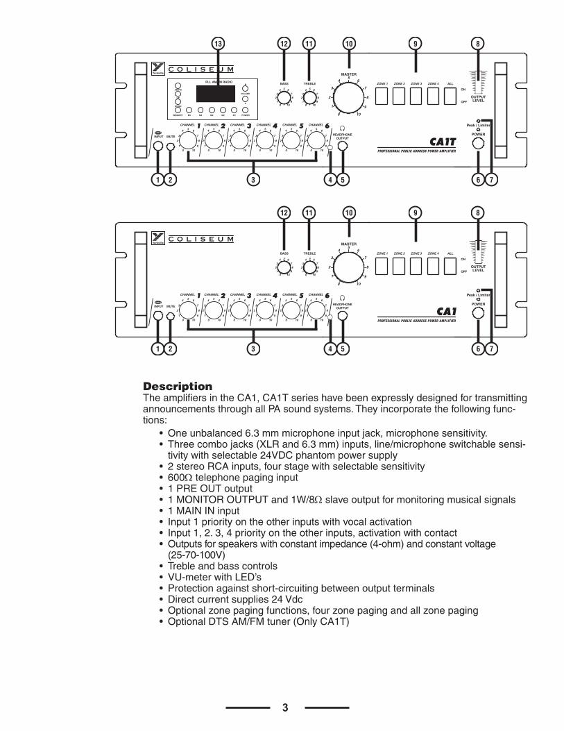
DescriptionTheamplifiersintheCA1,CA1TserieshavebeenexpresslydesignedfortransmittingannouncementsthroughallPAsoundsystems.Theyincorporatethefollowingfunc-tions:
• Oneunbalanced6.3mmmicrophoneinputjack,microphonesensitivity.• Threecombojacks(XLRand6.3mm)inputs,line/microphoneswitchablesensi-
tivitywithselectable24VDCphantompowersupply• 2stereoRCAinputs,fourstagewithselectablesensitivity• 600Ωtelephonepaginginput• 1PREOUToutput•1MONITOROUTPUTand1W/8Ωslaveoutputformonitoringmusicalsignals•1MAININinput•Input1priorityontheotherinputswithvocalactivation•Input1,2.3,4priorityontheotherinputs,activationwithcontact•Outputsforspeakerswithconstantimpedance(4-ohm)andconstantvoltage
(25-70-100V)•Trebleandbasscontrols•VU-meterwithLED’s•Protectionagainstshort-circuitingbetweenoutputterminals•Directcurrentsupplies24Vdc•Optionalzonepagingfunctions,fourzonepagingandallzonepaging•OptionalDTSAM/FMtuner(OnlyCA1T)
CA1TPROFESSIONAL PUBLIC ADDRESS POWER AMPLIFIER
CHANNEL 1 CHANNEL 2 CHANNEL 3 CHANNEL 4 CHANNEL 5 CHANNEL 6HEADPHONE
OUTPUT
BASS TREBLE
MASTER
ZONE 1 ZONE 2 ZONE 3 ZONE 4 ALL
MUTEINPUTPOWER
Peak / Limiter
ON
OFF
OUTPUTLEVEL
C O L I S E U M
10
9
82
1
73
0
654
10
9
82
1
73
0
654
10
9
82
1
73
0
654
10
9
82
1
73
0
654
10
9
82
1
73
0
654
10
9
82
1
73
0
654
10982
1
73
0
654
10982
1
73
0
654
10
9
82
1
73
0
65
4PLL AM/FM RADIO
M5 M4 M3 M2 M1 POWER
VOLUME
AM/FM
UP
DOWN
MEMORY
CA1PROFESSIONAL PUBLIC ADDRESS POWER AMPLIFIER
CHANNEL 1 CHANNEL 2 CHANNEL 3 CHANNEL 4 CHANNEL 5 CHANNEL 6HEADPHONE
OUTPUT
BASS TREBLE
MASTER
ZONE 1 ZONE 2 ZONE 3 ZONE 4 ALL
MUTEINPUTPOWER
Peak / Limiter
ON
OFF
OUTPUTLEVEL
C O L I S E U M
10
9
82
1
73
0
654
10
9
82
1
73
0
654
10
9
82
1
73
0
654
10
9
82
1
73
0
654
10
9
82
1
73
0
654
10
9
82
1
73
0
654
10982
1
73
0
654
10982
1
73
0
654
10
9
82
1
73
0
65
4
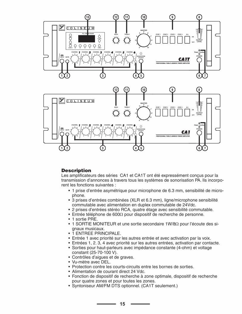
1 2 3 54 6 7
1 2 3 54 6 7
13 12 11 10 9 8
12 11 10 9 8
4
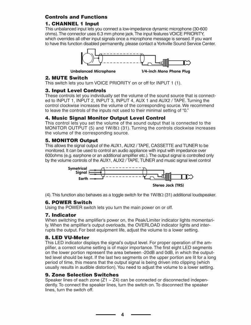
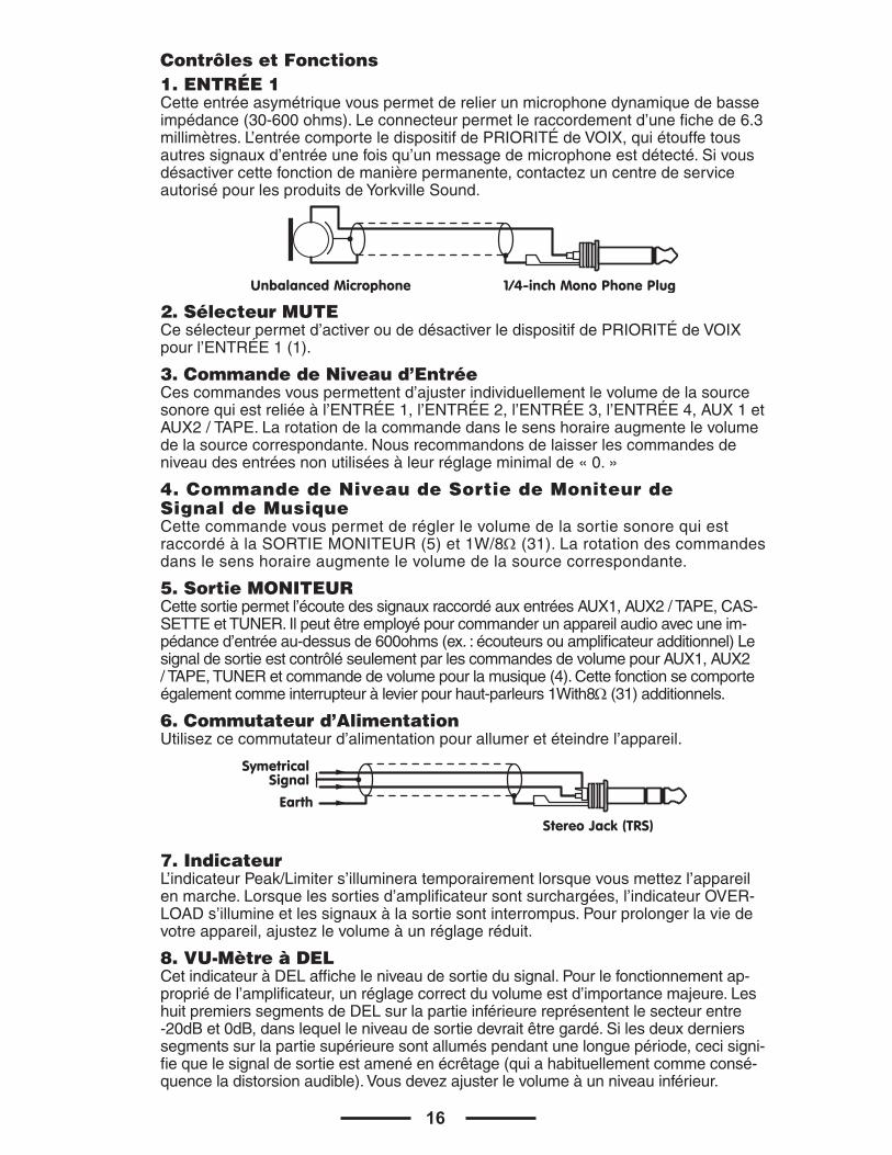
Controls and Functions1. CHANNEL 1 InputThisunbalancedinputletsyouconnectalow-impedancedynamicmicrophone(30-600ohms).Theconnectoruses6.3mmphonejack.TheinputfeaturesVOICEPRIORITY,whichoverridesallotherinputsignalsonceamicrophonemessageissensed.Ifyouwanttohavethisfunctiondisabledpermanently,pleasecontactaYorkvilleSoundServiceCenter.
2. MUTE Switch ThisswitchletsyouturnVOICEPRIORITYonoroffforINPUT1(1).
3. Input Level ControlsThesecontrolsletyouindividuallysetthevolumeofthesoundsourcethatisconnect-edtoINPUT1,INPUT2,INPUT3,INPUT4,AUX1andAUX2/TAPE.Turningthecontrolclockwiseincreasesthevolumeofthecorrespondingsource.Werecommendtoleavethecontrolsoftheinputsnotusedtotheirminimalsettingof“0.”
4. Music Signal Monitor Output Level Control ThiscontrolletsyousetthevolumeofthesoundoutputthatisconnectedtotheMONITOROUTPUT(5)and1W/8Ω(31).Turningthecontrolsclockwiseincreasesthevolumeofthecorrespondingsource.
5. MONITOR Output ThisallowsthesignaloutputoftheAUX1,AUX2/TAPE,CASSETTEandTUNERtobemonitored.Itcanbeusedtocontrolanaudioappliancewithinputwithimpedanceover600ohms(e.g.earphoneoranadditionalamplifieretc.).TheoutputsignaliscontrolledonlybythevolumecontrolsoftheAUX1,AUX2/TAPE,TUNERandmusicsignallevelcontrol
(4).Thisfunctionalsobehavesasatoggleswitchforthe1W/8Ω(31)additionalloudspeaker.
6. POWER Switch UsingthePOWERswitchletsyouturnthemainpoweronoroff.
7. Indicator Whenswitchingtheamplifier’spoweron,thePeak/Limiterindicatorlightsmomentari-ly.Whentheamplifier’soutputoverloads,theOVERLOADindicatorlightsandinter-ruptstheoutput.Forbestequipmentlife,adjustthevolumetoalowersetting.
8. LED VU-Meter ThisLEDindicatordisplaysthesignal’soutputlevel.Forproperoperationoftheam-plifier,acorrectvolumesettingisofmajorimportance.ThefirsteightLEDsegmentsonthelowerportionrepresenttheareabetween-20dBand0dB,inwhichtheoutput-tedlevelshouldbekept.Ifthelasttwosegmentsontheupperportionarelitforalongperiodoftime,thismeansthattheoutputsignalisbeingdrivenintoclipping(whichusuallyresultsinaudibledistortion).Youneedtoadjustthevolumetoalowersetting.
9. Zone Selection Switches Speakerlinesofeachzone(Z1~Z4)canbeconnectedordisconnectedindepen-dently.Toconnectthespeakerlines,turntheswitchon.Todisconnectthespeakerlines,turntheswitchoff.
1/4-inch Mono Phone PlugUnbalanced Microphone
Earth
SymetricalSignal
Stereo Jack (TRS)
5
Individualzonescanbeselectedbyturningtheseswitchesonoroff.Allspeakersconnectedtoaspecificzonemaybeturnedonoroffinthismanner.TheALLswitchoverridestheindividualswitchesandswitchesallzoneson,regardlessofwhetherornottheindividualzoneswitchisonoroff.
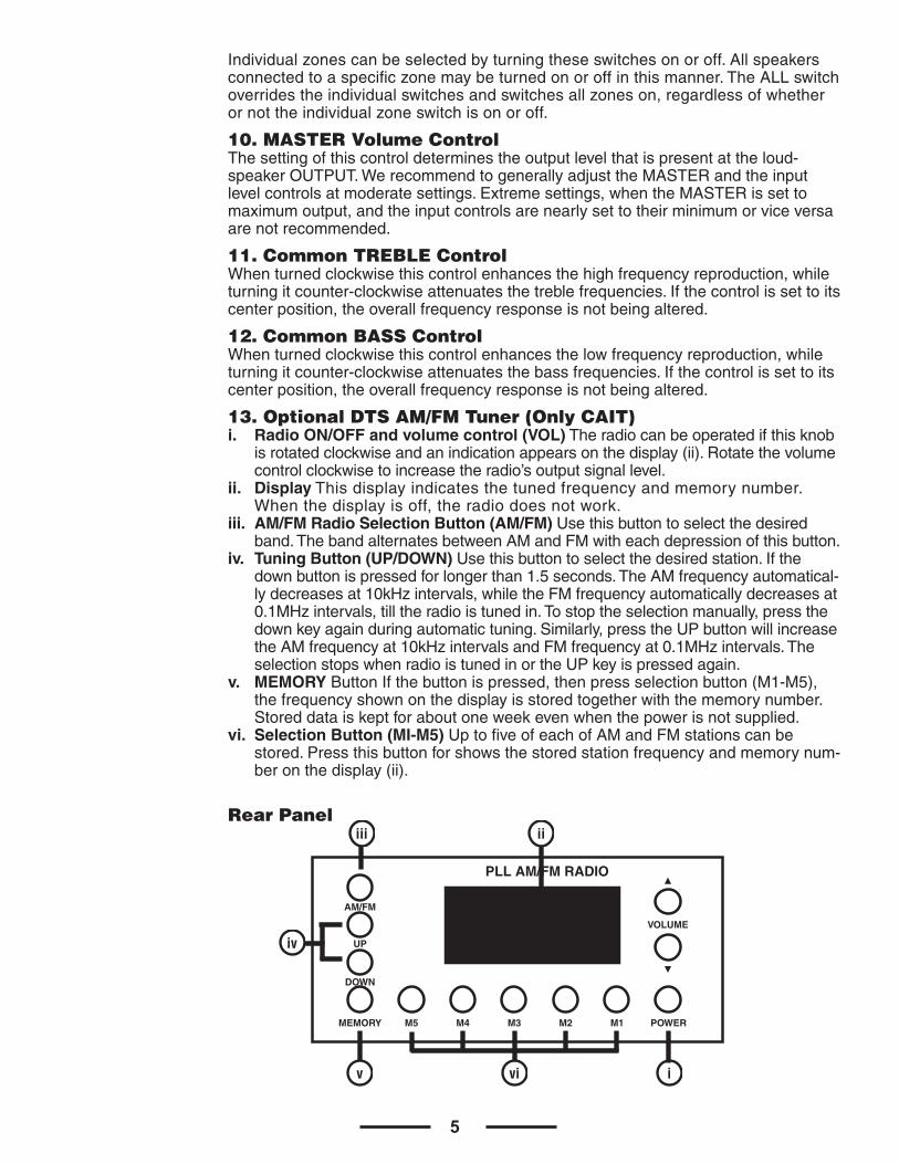
10. MASTER Volume ControlThesettingofthiscontroldeterminestheoutputlevelthatispresentattheloud-speakerOUTPUT.WerecommendtogenerallyadjusttheMASTERandtheinputlevelcontrolsatmoderatesettings.Extremesettings,whentheMASTERissettomaximumoutput,andtheinputcontrolsarenearlysettotheirminimumorviceversaarenotrecommended.
11. Common TREBLE ControlWhenturnedclockwisethiscontrolenhancesthehighfrequencyreproduction,whileturningitcounter-clockwiseattenuatesthetreblefrequencies.Ifthecontrolissettoitscenterposition,theoverallfrequencyresponseisnotbeingaltered.
12. Common BASS Control Whenturnedclockwisethiscontrolenhancesthelowfrequencyreproduction,whileturningitcounter-clockwiseattenuatesthebassfrequencies.Ifthecontrolissettoitscenterposition,theoverallfrequencyresponseisnotbeingaltered.
13. Optional DTS AM/FM Tuner (Only CAIT) i. Radio ON/OFF and volume control (VOL)Theradiocanbeoperatedifthisknob
isrotatedclockwiseandanindicationappearsonthedisplay(ii).Rotatethevolumecontrolclockwisetoincreasetheradio’soutputsignallevel.
ii. DisplayThisdisplayindicatesthetunedfrequencyandmemorynumber.Whenthedisplayisoff,theradiodoesnotwork.
iii. AM/FM Radio Selection Button (AM/FM) Usethisbuttontoselectthedesiredband.ThebandalternatesbetweenAMandFMwitheachdepressionofthisbutton.
iv. Tuning Button (UP/DOWN)Usethisbuttontoselectthedesiredstation.Ifthedownbuttonispressedforlongerthan1.5seconds.TheAMfrequencyautomatical-lydecreasesat10kHzintervals,whiletheFMfrequencyautomaticallydecreasesat0.1MHzintervals,tilltheradioistunedin.Tostoptheselectionmanually,pressthedownkeyagainduringautomatictuning.Similarly,presstheUPbuttonwillincreasetheAMfrequencyat10kHzintervalsandFMfrequencyat0.1MHzintervals.TheselectionstopswhenradioistunedinortheUPkeyispressedagain.
v. MEMORYButtonIfthebuttonispressed,thenpressselectionbutton(M1-M5),thefrequencyshownonthedisplayisstoredtogetherwiththememorynumber.Storeddataiskeptforaboutoneweekevenwhenthepowerisnotsupplied.
vi. Selection Button (MI-M5) UptofiveofeachofAMandFMstationscanbestored.Pressthisbuttonforshowsthestoredstationfrequencyandmemorynum-beronthedisplay(ii).
Rear Panel
PLL AM/FM RADIO
M5 M4 M3 M2 M1 POWER
VOLUME
AM/FM
UP
DOWN
MEMORY
i
iiiii
vi
iv
v
6
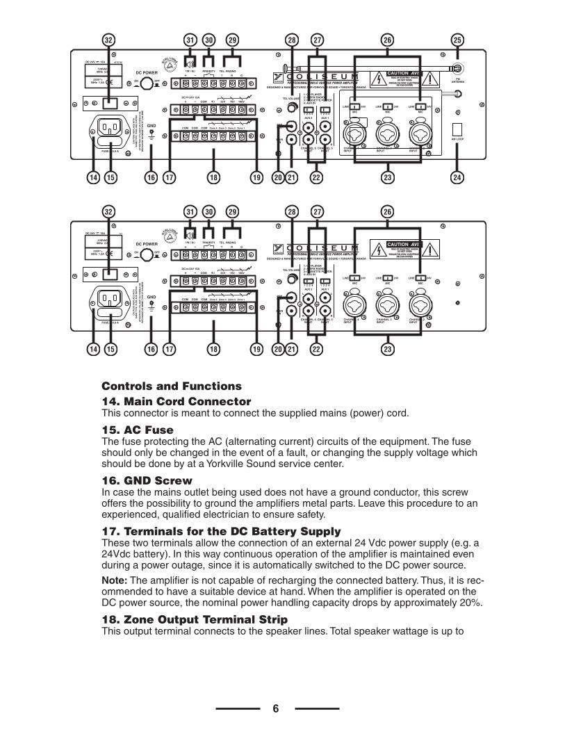
Controls and Functions 14. Main Cord ConnectorThisconnectorismeanttoconnectthesuppliedmains(power)cord.
15. AC FuseThefuseprotectingtheAC(alternatingcurrent)circuitsoftheequipment.Thefuseshouldonlybechangedintheeventofafault,orchangingthesupplyvoltagewhichshouldbedonebyataYorkvilleSoundservicecenter.
16. GND Screw Incasethemainsoutletbeinguseddoesnothaveagroundconductor,thisscrewoffersthepossibilitytogroundtheamplifiersmetalparts.Leavethisproceduretoanexperienced,qualifiedelectriciantoensuresafety.
17. Terminals for the DC Battery SupplyThesetwoterminalsallowtheconnectionofanexternal24Vdcpowersupply(e.g.a24Vdcbattery).Inthiswaycontinuousoperationoftheamplifierismaintainedevenduringapoweroutage,sinceitisautomaticallyswitchedtotheDCpowersource.
Note:Theamplifierisnotcapableofrechargingtheconnectedbattery.Thus,itisrec-ommendedtohaveasuitabledeviceathand.WhentheamplifierisoperatedontheDCpowersource,thenominalpowerhandlingcapacitydropsbyapproximately20%.
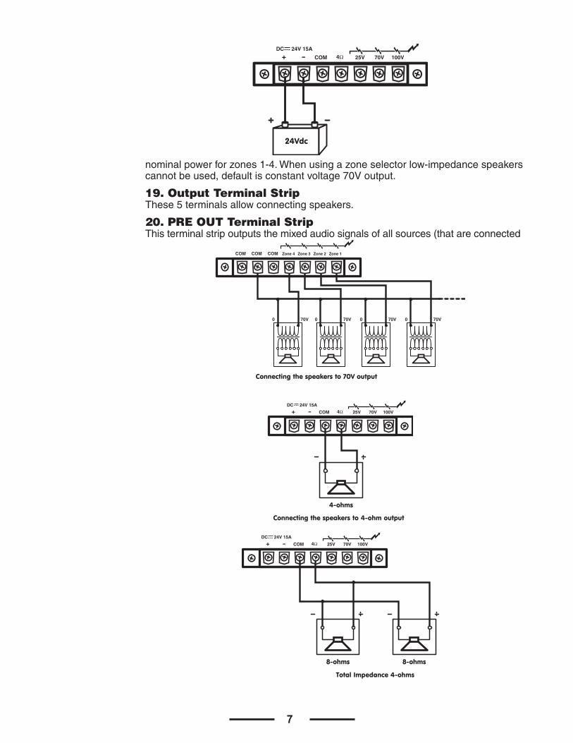
18. Zone Output Terminal Strip Thisoutputterminalconnectstothespeakerlines.Totalspeakerwattageisupto
DC POWER PRIORITY
COM
ON OFF
COM
MAININ
PREOUT
TEL VOLUME
1 42 3
1: CD PLAYER
4: AUX IN
CHANNEL 6INPUT
L
R
L
RCHANNEL 5
INPUTCHANNEL 4INPUT
CHANNEL 3INPUT
CHANNEL 2INPUT
MIC
LINE 24V
MIC
LINE 24V
MIC
LINE 24V
AUX 2 AUX 1
2: AM/FM RADIO3: CASSETTE PLAYER
1 42 3
COM COM Zone 4 Zone 3 Zone 2 Zone 1
25V 70V 100V
DC 24V 15A
TEL. PAGING
T R+ -
+ -
G
1W / 8Ω
4Ω
GND
C O L I S E U MPROFESSIONAL PUBLIC ADDRESS POWER AMPLIFIER
FUSE: T 5,0 A
CA
UT
ION
: RE
PL
AC
E W
ITH
SA
ME
TY
PE
FU
SE
AN
D R
AT
ING
AT
TE
NT
ION
: U
TIL
ISE
R U
N F
US
IBL
E D
ER
EC
HA
NG
E D
E M
EM
E T
YP
E E
T C
AL
IBR
E
DESIGNED & MANUFACTURED FOR YORKVILLE SOUND • TORONTO, CANADA
z515/1b5
230V 50Hz 1,3A
DC 24V 15A
120VAC 60Hz 2.6A
NTR
L Listed
AM LOOP
FMANTENNA
DC POWER PRIORITY
COM
ON OFF
COM
MAININ
PREOUT
TEL VOLUME
1 42 3
1: CD PLAYER
4: AUX IN
CHANNEL 6INPUT
L
R
L
RCHANNEL 5
INPUTCHANNEL 4INPUT
CHANNEL 3INPUT
CHANNEL 2INPUT
MIC
LINE 24V
MIC
LINE 24V
MIC
LINE 24V
AUX 2 AUX 1
2: AM/FM RADIO3: CASSETTE PLAYER
1 42 3
COM COM Zone 4 Zone 3 Zone 2 Zone 1
25V 70V 100V
DC 24V 15A
TEL. PAGING
T R+ -
+ -
G
1W / 8Ω
4Ω
GND
C O L I S E U MPROFESSIONAL PUBLIC ADDRESS POWER AMPLIFIER
FUSE: T 5,0 A
CA
UT
ION
: RE
PL
AC
E W
ITH
SA
ME
TY
PE
FU
SE
AN
D R
AT
ING
AT
TE
NT
ION
: U
TIL
ISE
R U
N F
US
IBL
E D
ER
EC
HA
NG
E D
E M
EM
E T
YP
E E
T C
AL
IBR
E
DESIGNED & MANUFACTURED FOR YORKVILLE SOUND • TORONTO, CANADA
120VAC 60Hz 2.6A
1v1
230V 50Hz 1,3A
DC 24V 15A NTR
L Listed
14 15 16 1817 21 24
28 26 25
19 20 22 23
2729303132
14 15 16 1817 21
28 26
19 20 22 23
2729303132
7
nominalpowerforzones1-4.Whenusingazoneselectorlow-impedancespeakerscannotbeused,defaultisconstantvoltage70Voutput.
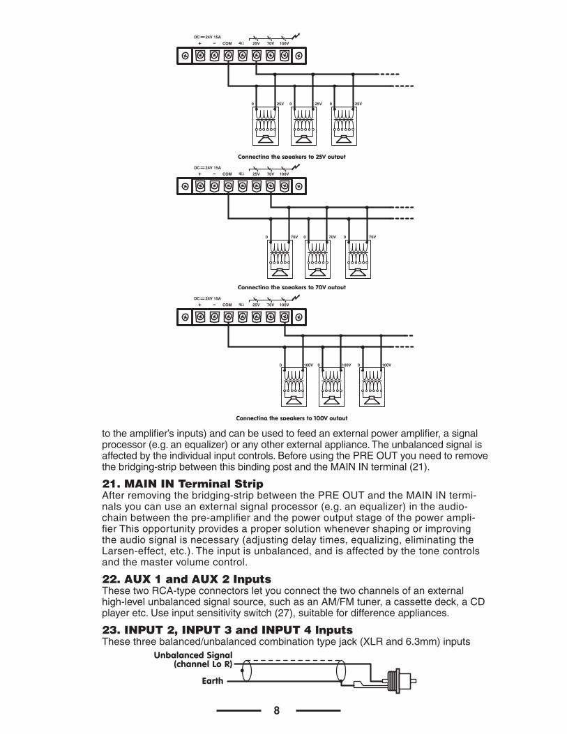
19. Output Terminal StripThese5terminalsallowconnectingspeakers.
20. PRE OUT Terminal Strip Thisterminalstripoutputsthemixedaudiosignalsofallsources(thatareconnected
COM 25V 70V 100V
DC 24V 15A
+ - 4Ω
24Vdc
COM
0 70V
COM COM Zone 4 Zone 3 Zone 2 Zone 1
0 70V 0 70V 0 70V
Connecting the speakers to 70V output
COM 25V 70V 100V
DC 24V 15A
+ - 4Ω
4-ohms
Connecting the speakers to 4-ohm output
COM 25V 70V 100V
DC 24V 15A
+ - 4Ω
8-ohms
Total Impedance 4-ohms
8-ohms
8
totheamplifier’sinputs)andcanbeusedtofeedanexternalpoweramplifier,asignalprocessor(e.g.anequalizer)oranyotherexternalappliance.Theunbalancedsignalisaffectedbytheindividualinputcontrols.BeforeusingthePREOUTyouneedtoremovethebridging-stripbetweenthisbindingpostandtheMAININterminal(21).
21. MAIN IN Terminal Strip Afterremovingthebridging-stripbetweenthePREOUTandtheMAININtermi-nalsyoucanuseanexternalsignalprocessor(e.g.anequalizer)intheaudio-chainbetweenthepre-amplifierandthepoweroutputstageofthepowerampli-fierThisopportunityprovidesapropersolutionwhenevershapingorimprovingtheaudiosignalisnecessary(adjustingdelaytimes,equalizing,eliminatingtheLarsen-effect,etc.).Theinputisunbalanced,andisaffectedbythetonecontrolsandthemastervolumecontrol.
22. AUX 1 and AUX 2 Inputs ThesetwoRCA-typeconnectorsletyouconnectthetwochannelsofanexternalhigh-levelunbalancedsignalsource,suchasanAM/FMtuner,acassettedeck,aCDplayeretc.Useinputsensitivityswitch(27),suitablefordifferenceappliances.
23. INPUT 2, INPUT 3 and INPUT 4 lnputs Thesethreebalanced/unbalancedcombinationtypejack(XLRand6.3mm)inputs
0 25V 0 25V 0 25V
COM 25V 70V 100V
DC 24V 15A
+ - 4Ω
Connecting the speakers to 25V output
0 70V 0 70V 0 70V
COM 25V 70V 100V
DC 24V 15A
+ - 4Ω
Connecting the speakers to 70V output
0 100V 0 100V 0 100V
COM 25V 70V 100V
DC 24V 15A
+ - 4Ω
Connecting the speakers to 100V output
RCA Plug
Unbalanced Signal(channel Lo R)
Earth
9
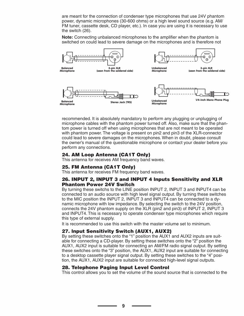
aremeantfortheconnectionofcondensertypemicrophonesthatuse24Vphantompower,dynamicmicrophones(30-600ohms)orahighlevelsoundsource(e.g.AM/FMtuner,cassettedesk,CDplayer,etc.).Incaseyouareusingitisnecessarytousetheswitch(26).
Note:Connectingunbalancedmicrophonestotheamplifierwhenthephantomisswitchedoncouldleadtoseveredamageonthemicrophonesandisthereforenot
recommended.Itisabsolutelymandatorytoperformanypluggingorunpluggingofmicrophonecableswiththephantompowerturnedoff.Also,makesurethatthephan-tompoweristurnedoffwhenusingmicrophonesthatarenotmeanttobeoperatedwithphantompower.Thevoltageispresentonpin2andpin3oftheXLR-connectorcouldleadtoseveredamagesonthemicrophones.Whenindoubt,pleaseconsulttheowner’smanualofthequestionablemicrophoneorcontactyourdealerbeforeyouperformanyconnections.
24. AM Loop Antenna (CA1T Only)ThisantennaforreceivesAMfrequencybandwaves.
25. FM Antenna (CA1T Only) ThisantennaforreceivesFMfrequencybandwaves.
26. INPUT 2, INPUT 3 and INPUT 4 lnputs Sensitivity and XLR Phantom Power 24V Switch ByturningtheseswitchstotheLINEpositionINPUT2,INPUT3andINPUT4canbeconnectedtoanaudiosourcewithhighlevelsignaloutput.ByturningtheseswitchestotheMICpositiontheINPUT2,INPUT3andINPUT4canbeconnectedtoady-namicmicrophonewithlowimpedance.Byselectingtheswitchtothe24Vposition,connectsthe24VphantomsupplyontheXLR(pin2andpin3)ofINPUT2,INPUT3andINPUT4.Thisisnecessarytooperatecondensertypemicrophoneswhichrequirethistypeofexternalsupply.Itisrecommendedtousethisswitchwiththemastervolumesettominimum.
27. lnput Sensitivity Switch (AUX1, AUX2)Bysettingtheseswitchesontothe“1”positiontheAUX1andAUX2inputsaresuit-ableforconnectingaCD-player.Bysettingtheseswitchesontothe“2”positiontheAUX1,AUX2inputissuitableforconnectinganAM/FMradiosignaloutput.Bysettingtheseswitchesontothe“3”position,theAUX1,AUX2inputaresuitableforconnectingtoadesktopcassetteplayersignaloutput.Bysettingtheseswitchestothe“4”posi-tion,theAUX1,AUX2inputaresuitableforconnectedhigh-levelsignaloutputs.
28. Telephone Paging Input Level ControlThiscontrolallowsyoutosetthevolumeofthesoundsourcethatisconnectedtothe
3-pin XLR (seen from the soldered side)
BalancedMicrophone
123
3-pin XLR (seen from the soldered side)
UnbalancedMicrophone
123
Stereo Jack (TRS)BalancedMicrophone
UnbalancedMicrophone
1/4-inch Mono Phone Plug
10
TEL.Paging(29)terminal.Turningcontrolclockwiseincreasesthevolumeofthecor-respondingsource.Werecommendtoleavethecontrolattheirminimalsettingof“0”ifnotused.
29. lnput TEL. PagingTheterminalstripinputletsyouconnecttoatelephonesignal(600ohms).TheinputfeaturesaVOICEPRIORITYfunction,whichoverridesallotherinputsignalsonceatelephonesignalissensed.Ifyouwanttohavethisfunctiondisabledpermanently,pleasecontactaYorkvilleSoundServiceCenter.
30. Priority TerminalWhenshort-circuitingtheseterminals(i.e.bymeansofusinganelectricalswitch),theaudiosignalscomingfromAUX1,AUX2/TAPE,CASSETTEandTUNERareattenu-atedwhilethesignalscomingfromINPUT1,INPUT2andINPUT4havepriority.
31. Output Terminal for Auxiliary Loudspeaker Thisterminalismeanttoconnectasmallexternalloudspeakerthatisdrivenbyan
internalauxiliarypoweramplifier,providinganominaloutput1watt.OnlythemixedaudiosignalcomingfromAUX1,AUX2/TAPE,CASSETTEandTUNERareincludedintheoutputtedsignal.Inaddition,theoutputsignaliscontrolledonlybythevolumecontrolsoftheAUX1,AUX2/TAPE,TUNERandmusicsignallevelcontrol(4).ThisfunctionistoggledbythetheMONITOROUTPUT(5).
32. DC switchThisswitchletsyouturnthebatterysupplyonoroff
INSTALLATION NOTES Atalltimes,theamplifierhastobeoperatedunderappropriateconditions.Thisincludesthattheoperationlocationprovidedsufficientventilationandthedeviceis
PRIORITY TEL. PAGING
T R+ - G
1W / 8Ω
AuxiliaryContact
PRIORITY TEL. PAGING
T R+ - G
1W / 8Ω
1W 8-ohms
11
notexposedtodirectsunlightordirectradiationorreflectionfromanyheatsource.Installingtheloudspeakersystemschoosealocationthatgetsnotaffectedbyex-tremeand/orconstantvibrationorothermechanicaloscillation.Alsomakesurethatthespeakersareinstalledatlocationsthatarefreefromdustand/ormoisture.
CAUTION Westronglyrecommendthatyouleavetheconnectionoftheappliancetothequalifiedandexperiencedservicetechnicalwhoisspecializedinconnectingelectricalandelectroni-callyequipment.Donottaketheriskofelectro-shockorshockhazard.Toreducetheriskofelectro-shockallconnectionshavetobeaccomplishedbeforeitispermissibletoconnecttheamplifiertothemainsupply.Beforeconnectingtheappliancetothemainssupply,onceagainmakecertainthatallconnectionsarecarriedoutcorrectlyandthatnoshort-circuitsexist.Theoverallsoundreinforcementinstallationhastobeinaccordancetothelawsregu-lations,standardsandguidelinesthatarerelevantandapplicableinthecountrywheretheequipmentisgoingtobeoperated.
AC POWER SUPPLY CAUTION
BeforeusingtheamplifierforthefirsttimemakesurethattheapplianceISsetinac-cordancetoyourmainssupply.Otherwise,pleaseconsultyourYorkvilledealerwhowillconfigureyourequipmentforthecorrectvoltage.Connecttheamplifieronlytogroundedmainsoutlets.Connectingtheamplifiertothemainssupply(115Vacre-spectively230Vac)hastobeaccomplishedbyinsertingthesuppliedmainscordintothecorrespondingsocket(15)andafterwardpluggingitintoamainsoutlet.
DC POWER SUPPLY CAUTION
A24VDCpowersource(ie.abattery)hastobeconnectedtotheterminals(18)thatarecoveredbytheprotectivelid.Toreducetheriskofdroppingvoltagetoaminimumandtoeliminatethedangerofdamagingthebatterycablesbythermaloverload,thesecableshavetobeatleast2.5mm2indiameter,each.Switchingtheamplifieronoroffisperformedthroughthepowerswitch(33).
CONNECTING THE OUTPUT TERMINALS CAUTION
Toavoidtheriskofelectricalshock,never touchthebareconductorsleadingtotheoutputterminalsoftheamplifierwhenitisinoperation.Underfigures,showthepos-sibleconnectionsoftheeOUTPUTspeakerterminalsaccessiblebyremovingtheprotectivecover.Bearinmindthefollowingrules:
Constant Impedance Lines•Thetotalimpedanceofthespeakersconnectedmust correspond to that selected on amplifier’s output terminals. •Thesumofthepowercapacitiesofthespeakersmustbenolowerthantheamplifier’spowercapacity.•Thelengthoftheconnectingcablesmustbeaspossible;inanycase,thelongerthedistancetobecoveredandthegreatermustbethecross-sectionofthecables.
Constant voltage lines •Eachspeakermustbeequippedwithalinetransformerwithaninputvoltageequaltothatoftheline(25,70,100V).•Thesumofthepowercapacitiesofthespeakersmustnot exceed the output power capacity of the amplifier (i.e. total wattage of speakers installed in zones 1 through 4).
12
Technical dataAmplifier section Type 60W-Mono-tabletop 120W-Mono-tabletop
Outputpowercapacity Nominal:60W-maximum:90W Nominal:120W-maximum:18OW
Nominalpowercapacity 45Wwithsupplyat24Vdc 90W
Frequencyresponse 50-15,000Hz(±3dB)
Totalharmonicdistortion ≤1%(1kHz-nominalpowercapacity)
Signal/noiseratio INPUT1-4,AUX1,2:>45dB MAININ:>55dB
Inputs/sensitivity-impedance INPUT1/6.3mmjack/-54dB(2mV)-300Ω/unbalanced INPUT2-4/XLRand6.3mmcombinationsocket/balanced Micro:-60dB(1mV)-600Ω Line:-22dB(75mV)-47KΩ AUX1-2/stereoRCAjack/unbalanced 1:0dB(1V)-240Ω(forCDplayer) 2:-6dB(500mV)-120KΩ(fortunerradio) 3:-10dB(300mV)-75KΩ(torcassetteplayer) 4:-20dB(100mV)-24KΩ(forauxiliaryappliance) MAlNIN/monoRCAjack10dB(1V)-1OKΩ/unbalanced
Outputsforspeakers/ohms 4ohms
Outputsforspeakers/Volts 25V-70V-100V(10Ω,83Ω,170Ω) 25V-70V-100V(5Ω,42Ω,83Ω)
Additionaloutputs PREOUT/monoRCAjack/1V-600Ω/unbalanced/voltage-impedance Loudspeaker/onterminalboard/1watt-8Ω Monitoroutput/6.3mmjack/1.5V-6OOΩ/balanced
Tonecontrols Bass±10dB-100Hz Treble±10dB-10kHz
Controls 7volumecontrolsforINPUT1-4,AUX1-2andtel.paging 1mastervolumecontrol 1treblecontrol 1basscontrol 5zonepagingselectswitch
Powersupply/Consumption 115/230Vac(±5%)-60/50Hz/200VA 115/230Vac(±5%)-60/50Hz/400VA
Directcurrentdraw(24V) 5A 10A
Dimensions(LxHxW) 480mmx320mmx150mm
Weight CA1:9kg CA1T:12kg
DTS radio tuner section Band AM/FM
Tuningrange AM:530kHz-1600kHzin10kHzsteps FM:87.5MHz-108MHzin100kHzsteps
Controls RadioON/OFFwithvolumecontrol Bandselectorbutton FrequencyUP/DOWNbutton Memorybutton5memorybuttons
Indicator LCD
13
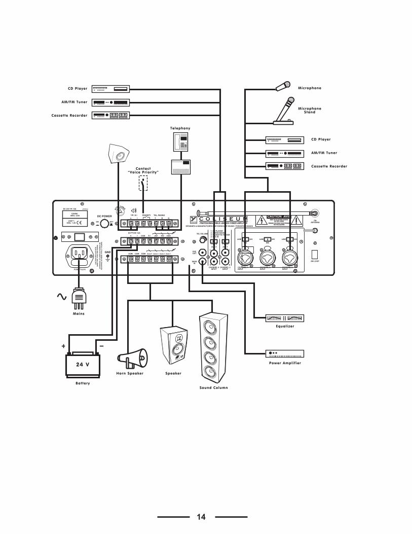
Example of possible connections
CA1TPROFESSIONAL PUBLIC ADDRESS POWER AMPLIFIER
CHANNEL 1 CHANNEL 2 CHANNEL 3 CHANNEL 4 CHANNEL 5 CHANNEL 6HEADPHONE
OUTPUT
BASS TREBLE
MASTERPAGING SELECTION
ZONE 1 ZONE 2 ZONE 3 ZONE 4 ALL
MUTEINPUTPOWER
Peak / Limiter
ON
OFF
OUTPUTLEVEL
C O L I S E U M
10
9
82
1
73
0
654
10
9
82
1
73
0
654
10
9
82
1
73
0
654
10
9
82
1
73
0
654
10
9
82
1
73
0
654
10
9
82
1
73
0
654
10982
1
73
0
654
10982
1
73
0
654
10
9
82
1
73
0
65
4PLL AM/FM RADIO
M1 M2 M3 M4 M5 MEMORY DOWN
UP
AM/FM
VOL
Microphone
MicrophoneStand
Headphones
CA1PROFESSIONAL PUBLIC ADDRESS POWER AMPLIFIER
CHANNEL 1 CHANNEL 2 CHANNEL 3 CHANNEL 4 CHANNEL 5 CHANNEL 6HEADPHONE
OUTPUT
BASS TREBLE
MASTERPAGING SELECTION
ZONE 1 ZONE 2 ZONE 3 ZONE 4 ALL
MUTEINPUTPOWER
Peak / Limiter
ON
OFF
OUTPUTLEVEL
C O L I S E U M
10
9
82
1
73
0
654
10
9
82
1
73
0
654
10
9
82
1
73
0
654
10
9
82
1
73
0
654
10
9
82
1
73
0
654
10
9
82
1
73
0
654
10982
1
73
0
654
10982
1
73
0
654
10
9
82
1
73
0
65
4
Microphone
MicrophoneStand
Headphones
14
DC POWER PRIORITY
COM
ON OFF
COM
MAININ
PREOUT
TEL VOLUME
1 42 3
1: CD PLAYER
4: AUX IN
CHANNEL 6INPUT
L
R
L
RCHANNEL 5
INPUTCHANNEL 4INPUT
CHANNEL 3INPUT
CHANNEL 2INPUT
MIC
LINE 24V
MIC
LINE 24V
MIC
LINE 24V
AUX 2 AUX 1
2: AM/FM RADIO3: CASSETTE PLAYER
1 42 3
COM COM Zone 4 Zone 3 Zone 2 Zone 1
25V 70V 100V
DC 24V 15A
TEL. PAGING
T R+ -
+ -
G
1W / 8Ω
4Ω
GND
C O L I S E U MPROFESSIONAL PUBLIC ADDRESS POWER AMPLIFIER
FUSE: T 5,0 A
CA
UT
ION
: RE
PL
AC
E W
ITH
SA
ME
TY
PE
FU
SE
AN
D R
AT
ING
AT
TE
NT
ION
: U
TIL
ISE
R U
N F
US
IBL
E D
ER
EC
HA
NG
E D
E M
EM
E T
YP
E E
T C
AL
IBR
E
DESIGNED & MANUFACTURED FOR YORKVILLE SOUND • TORONTO, CANADA
z515/1b5
230V 50Hz 1,3A
DC 24V 15A
120VAC 60Hz 2.6A
NTR
L Listed
AM LOOP
FMANTENNA
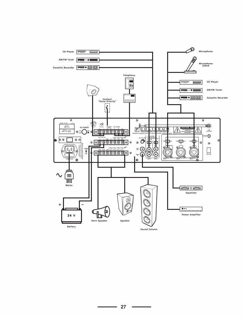
MicrophoneCD Player
AM/FM Tuner
Cassette Recorder
MicrophoneStand
24 V
CD Player
AM/FM Tuner
Cassette RecorderContact
“Voice Priority”
Telephony
Mains
Battery
Horn Speaker Speaker
Sound Column
Power Amplif ier
Equalizer
15
DescriptionLesamplificateursdessériesCA1etCA1Tontétéexpressémentconçuspourlatransmissiond’annoncesàtraverstouslessystèmesdesonorisationPA.Ilsincorpo-rentlesfonctionssuivantes:
• 1prised’entréeasymétriquepourmicrophonede6.3mm,sensibilitédemicro-phone.
• 3prisesd’entréescombinées(XLRet6.3mm),ligne/microphonesensibilitécommutableavecalimentationenduplexcommutablede24Vdc.
• 2prisesd’entréesstéréoRCA,quatreétageavecsensibilitécommutable.• Entréetéléphonede600Ωpourdispositifderecherchedepersonne.• 1sortiePRE.•1SORTIEMONITEURetunesortiesecondaire1W/8Ωpourl’écoutedessi-
gnauxmusicaux.•1ENTREEPRINCIPALE.•Entrée1avecprioritésurlesautresentréeetavecactivationparlavoix.•Entrées1,2.3,4avecprioritésurlesautresentrées,activationparcontacte.•Sortiespourhaut-parleursavecimpédanceconstante(4-ohm)etvoltage
constant(25-70-100V).•Contrôlesd’aiguesetdegraves.•Vu-mètreavecDEL.•Protectioncontrelescourts-circuitsentrelesbornesdesorties.•Alimentationdecourantdirect24Vdc.•Fonctiondedispositifderechercheàzoneoptimale,dispositifderecherche
pourquatrezonesetpourtoutesleszones.•SyntoniseurAM/FMDTSoptionnel.(CA1Tseulement.)
CA1TPROFESSIONAL PUBLIC ADDRESS POWER AMPLIFIER
CHANNEL 1 CHANNEL 2 CHANNEL 3 CHANNEL 4 CHANNEL 5 CHANNEL 6HEADPHONE
OUTPUT
BASS TREBLE
MASTER
ZONE 1 ZONE 2 ZONE 3 ZONE 4 ALL
MUTEINPUTPOWER
Peak / Limiter
ON
OFF
OUTPUTLEVEL
C O L I S E U M
10
9
82
1
73
0
654
10
9
82
1
73
0
654
10
9
82
1
73
0
654
10
9
82
1
73
0
654
10
9
82
1
73
0
654
10
9
82
1
73
0
654
10982
1
73
0
654
10982
1
73
0
654
10
9
82
1
73
0
65
4PLL AM/FM RADIO
M5 M4 M3 M2 M1 POWER
VOLUME
AM/FM
UP
DOWN
MEMORY
CA1PROFESSIONAL PUBLIC ADDRESS POWER AMPLIFIER
CHANNEL 1 CHANNEL 2 CHANNEL 3 CHANNEL 4 CHANNEL 5 CHANNEL 6HEADPHONE
OUTPUT
BASS TREBLE
MASTER
ZONE 1 ZONE 2 ZONE 3 ZONE 4 ALL
MUTEINPUTPOWER
Peak / Limiter
ON
OFF
OUTPUTLEVEL
C O L I S E U M
10
9
82
1
73
0
654
10
9
82
1
73
0
654
10
9
82
1
73
0
654
10
9
82
1
73
0
654
10
9
82
1
73
0
654
10
9
82
1
73
0
654
10982
1
73
0
654
10982
1
73
0
654
10
9
82
1
73
0
65
4
1 2 3 54 6 7
1 2 3 54 6 7
13 12 11 10 9 8
12 11 10 9 8
16
Contrôles et Fonctions1. ENTRÉE 1 Cetteentréeasymétriquevouspermetderelierunmicrophonedynamiquedebasseimpédance(30-600ohms).Leconnecteurpermetleraccordementd’unefichede6.3millimètres.L’entréecomporteledispositifdePRIORITÉdeVOIX,quiétouffetousautressignauxd’entréeunefoisqu’unmessagedemicrophoneestdétecté.Sivousdésactivercettefonctiondemanièrepermanente,contactezuncentredeserviceautorisépourlesproduitsdeYorkvilleSound.
2. Sélecteur MUTE Cesélecteurpermetd’activeroudedésactiverledispositifdePRIORITÉdeVOIXpourl’ENTRÉE1(1).
3. Commande de Niveau d’Entrée Cescommandesvouspermettentd’ajusterindividuellementlevolumedelasourcesonorequiestreliéeàl’ENTRÉE1,l’ENTRÉE2,l’ENTRÉE3,l’ENTRÉE4,AUX1etAUX2/TAPE.Larotationdelacommandedanslesenshoraireaugmentelevolumedelasourcecorrespondante.Nousrecommandonsdelaisserlescommandesdeniveaudesentréesnonutiliséesàleurréglageminimalde«0.»
4. Commande de Niveau de Sortie de Moniteur de Signal de MusiqueCettecommandevouspermetderéglerlevolumedelasortiesonorequiestraccordéàlaSORTIEMONITEUR(5)et1W/8Ω(31).Larotationdescommandesdanslesenshoraireaugmentelevolumedelasourcecorrespondante.
5. Sortie MONITEUR Cettesortiepermetl’écoutedessignauxraccordéauxentréesAUX1,AUX2/TAPE,CAS-SETTEetTUNER.Ilpeutêtreemployépourcommanderunappareilaudioavecuneim-pédanced’entréeau-dessusde600ohms(ex.:écouteursouamplificateuradditionnel)LesignaldesortieestcontrôléseulementparlescommandesdevolumepourAUX1,AUX2/TAPE,TUNERetcommandedevolumepourlamusique(4).Cettefonctionsecomporteégalementcommeinterrupteuràlevierpourhaut-parleurs1With8Ω(31)additionnels.
6. Commutateur d’Alimentation Utilisezcecommutateurd’alimentationpourallumeretéteindrel’appareil.
7. Indicateur L’indicateurPeak/Limiters’illumineratemporairementlorsquevousmettezl’appareilenmarche.Lorsquelessortiesd’amplificateursontsurchargées,l’indicateurOVER-LOADs’illumineetlessignauxàlasortiesontinterrompus.Pourprolongerlaviedevotreappareil,ajustezlevolumeàunréglageréduit.
8. VU-Mètre à DEL CetindicateuràDELafficheleniveaudesortiedusignal.Pourlefonctionnementap-propriédel’amplificateur,unréglagecorrectduvolumeestd’importancemajeure.LeshuitpremierssegmentsdeDELsurlapartieinférieurereprésententlesecteurentre-20dBet0dB,danslequelleniveaudesortiedevraitêtregardé.Silesdeuxdernierssegmentssurlapartiesupérieuresontalluméspendantunelonguepériode,cecisigni-fiequelesignaldesortieestamenéenécrêtage(quiahabituellementcommeconsé-quenceladistorsionaudible).Vousdevezajusterlevolumeàunniveauinférieur.
1/4-inch Mono Phone PlugUnbalanced Microphone
Earth
SymetricalSignal
Stereo Jack (TRS)
17
9. Commutateur de Sélection de Zone Leslignesdehaut-parleurpourchaquezone(Z1~Z4)peuventêtreconnectésoudéconnectésindépendamment.Pourconnecterleslignesdehaut-parleur,réglezlecommutateuràlapositionON.Pourdéconnecterleslignesdehaut-parleur,réglezlecommutateuràlapositionOFF.LeszonesindividuellespeuventêtresélectionnéesenréglantcescommutateursàONouOFF.Tousleshaut-parleursconnectésàunezonespécifiquepeuventêtresarméoudésarmésdecettefaçon.LecommutateurALLl’emportesurlescommu-tateursindividuelsetarmetoutesleszones,peutimportlapositionducommutateurindividuelpourchaquezone.
10. Commande MASTER VolumeLeréglagedecettecommandedétermineleniveaudesortiequiestprésentàlasortiedehaut-parleur.NousrecommandonsdegénéralementajusterlacommandeMASTERetlescommandesdeniveaud’entréeàdesniveauxmodérés.Desréglagesextrêmes,quandlacommandeMASTERestajustéeaumaximum,etlescommandesd’entréesontpresqueàleurniveauminimumouviceversanesontpasrecommandés.
11. Commande TREBLE CommuneTournezcettecommandedanslesenshorairepourrehausserlareproductiondesaiguës.Tournez-ladanslesensanti-horairepouratténuerleniveaudesaiguës.Laréponseenfréquenceengénéraln’estpasaffectéesilacommandeestrégléeàlapositioncentrale.
12. Commande BASS CommuneTournezcettecommandedanslesenshorairepourrehausserlareproductiondesgraves.Tournez-ladanslesensanti-horairepouratténuerleniveaudesgraves.Laréponseenfréquenceengénéraln’estpasaffectéesilacommandeestrégléeàlapositioncentrale.
13. Syntoniseur AM/FM DTS Optionnel (CAIT seulement) i. Radio ON/OFF et commande de volume (VOL)Laradiopeutêtreutiliséesi
cettecommandeesttournéedanslesenshoraireetuneindicationapparaîtsurl’affichage(ii).Tournezlacommandedevolumedanslesenshorairepouraugmen-terleniveaudusignaledesortiedelaradio.
ii. Affichage Cetaffichageindiquelafréquencesélectionnéeetlenumérodemémoire.
iii. Bouton de sélection AM/FM pour la Radio Utilisezceboutonpoursélectionnerlabandedésirée.Avecchaquepousséeduboutonvousalternezentrelesban-desAMetFM.
iv. Bouton de syntonisation (UP/DOWN)Utilisezceboutonpourchoisirlastationdésirée.Sivousappuyezsurlebouton“down”pendantplusde1.5seconde,lafréquenceAMdiminueautomatiquementàdesintervallesde10kHz,alorsquelafréquenceFMdiminueautomatiquementàdesintervallesde0.1MHz,jusqu’àcequelaradiosoitsyntonisée.Pourarrêtermanuellementàlasélectiondésirée,appuyezsurlebouton“down”ànouveaudurantlasyntonisationautomatique.Demême,enappuyantsurlebouton“up”,vousaugmenterezlafréquenceAMàdesintervallesde10kHzetlafréquenceFMàdesintervallesde0.1MHz.Lasélections’arrêtelorsquelaradioestsyntoniséeouquandvousappuyezànouveausurlebouton«UP».
v. Le Bouton MEMORYSivousappuyezsurcebouton,etensuitelebouton“se-lection”(M1-M5),lafréquenceindiquéesurl’affichageestsauvegardédemêmequelenumérodemémoire.L’informationsauvegardéeestgardéenmémoirepourenvironunesemainemêmequandl’appareiln’estpasbranchéàunesourced’alimentation.
vi. Bouton “Selection” (MI-M5) Vouspouvezsauvegarderjusqu’àcinqstationsAMetcinqFM.Appuyezsurceboutonpourexposerlafréquencesauvegardéedestationetlenumérodemémoiresurl’affichage(ii).
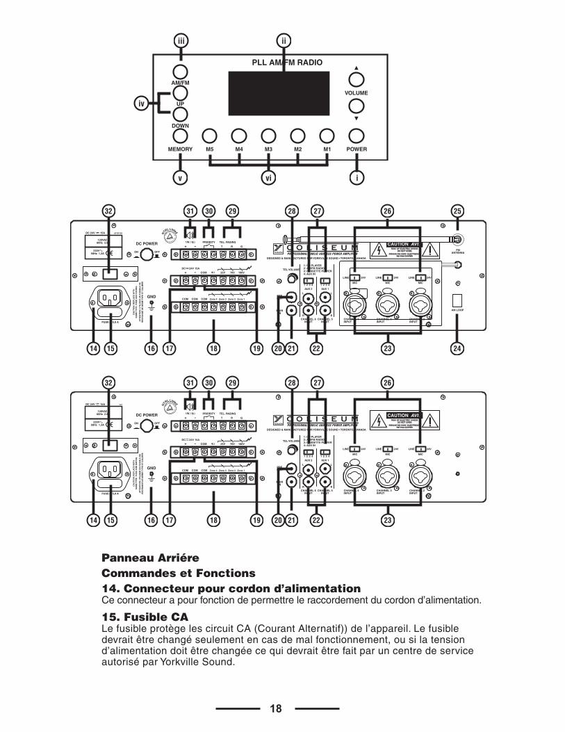
18
Panneau Arriére Commandes et Fonctions 14. Connecteur pour cordon d’alimentationCeconnecteurapourfonctiondepermettreleraccordementducordond’alimentation.
15. Fusible CA LefusibleprotègelescircuitCA(CourantAlternatif))del’appareil.Lefusibledevraitêtrechangéseulementencasdemalfonctionnement,ousilatensiond’alimentationdoitêtrechangéecequidevraitêtrefaitparuncentredeserviceautoriséparYorkvilleSound.
DC POWER PRIORITY
COM
ON OFF
COM
MAININ
PREOUT
TEL VOLUME
1 42 3
1: CD PLAYER
4: AUX IN
CHANNEL 6INPUT
L
R
L
RCHANNEL 5
INPUTCHANNEL 4INPUT
CHANNEL 3INPUT
CHANNEL 2INPUT
MIC
LINE 24V
MIC
LINE 24V
MIC
LINE 24V
AUX 2 AUX 1
2: AM/FM RADIO3: CASSETTE PLAYER
1 42 3
COM COM Zone 4 Zone 3 Zone 2 Zone 1
25V 70V 100V
DC 24V 15A
TEL. PAGING
T R+ -
+ -
G
1W / 8Ω
4Ω
GND
C O L I S E U MPROFESSIONAL PUBLIC ADDRESS POWER AMPLIFIER
FUSE: T 5,0 A
CA
UT
ION
: RE
PL
AC
E W
ITH
SA
ME
TY
PE
FU
SE
AN
D R
AT
ING
AT
TE
NT
ION
: U
TIL
ISE
R U
N F
US
IBL
E D
ER
EC
HA
NG
E D
E M
EM
E T
YP
E E
T C
AL
IBR
E
DESIGNED & MANUFACTURED FOR YORKVILLE SOUND • TORONTO, CANADA
z515/1b5
230V 50Hz 1,3A
DC 24V 15A
120VAC 60Hz 2.6A
NTR
L Listed
AM LOOP
FMANTENNA
DC POWER PRIORITY
COM
ON OFF
COM
MAININ
PREOUT
TEL VOLUME
1 42 3
1: CD PLAYER
4: AUX IN
CHANNEL 6INPUT
L
R
L
RCHANNEL 5
INPUTCHANNEL 4INPUT
CHANNEL 3INPUT
CHANNEL 2INPUT
MIC
LINE 24V
MIC
LINE 24V
MIC
LINE 24V
AUX 2 AUX 1
2: AM/FM RADIO3: CASSETTE PLAYER
1 42 3
COM COM Zone 4 Zone 3 Zone 2 Zone 1
25V 70V 100V
DC 24V 15A
TEL. PAGING
T R+ -
+ -
G
1W / 8Ω
4Ω
GND
C O L I S E U MPROFESSIONAL PUBLIC ADDRESS POWER AMPLIFIER
FUSE: T 5,0 A
CA
UT
ION
: RE
PL
AC
E W
ITH
SA
ME
TY
PE
FU
SE
AN
D R
AT
ING
AT
TE
NT
ION
: U
TIL
ISE
R U
N F
US
IBL
E D
ER
EC
HA
NG
E D
E M
EM
E T
YP
E E
T C
AL
IBR
E
DESIGNED & MANUFACTURED FOR YORKVILLE SOUND • TORONTO, CANADA
120VAC 60Hz 2.6A
1v1
230V 50Hz 1,3A
DC 24V 15A NTR
L Listed
14 15 16 1817 21 24
28 26 25
19 20 22 23
2729303132
14 15 16 1817 21
28 26
19 20 22 23
2729303132
PLL AM/FM RADIO
M5 M4 M3 M2 M1 POWER
VOLUME
AM/FM
UP
DOWN
MEMORY
i
iiiii
vi
iv
v
19
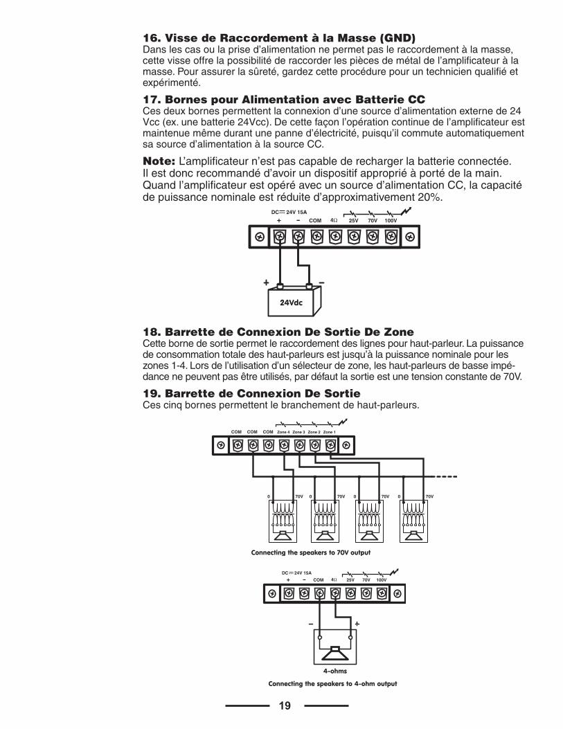
16. Visse de Raccordement à la Masse (GND) Danslescasoulaprised’alimentationnepermetpasleraccordementàlamasse,cettevisseoffrelapossibilitéderaccorderlespiècesdemétaldel’amplificateuràlamasse.Pourassurerlasûreté,gardezcetteprocédurepouruntechnicienqualifiéetexpérimenté.
17. Bornes pour Alimentation avec Batterie CCCesdeuxbornespermettentlaconnexiond’unesourced’alimentationexternede24Vcc(ex.unebatterie24Vcc).Decettefaçonl’opérationcontinuedel’amplificateurestmaintenuemêmedurantunepanned’électricité,puisqu’ilcommuteautomatiquementsasourced’alimentationàlasourceCC.
Note: L’amplificateurn’estpascapablederechargerlabatterieconnectée.Ilestdoncrecommandéd’avoirundispositifappropriéàportédelamain.Quandl’amplificateurestopéréavecunsourced’alimentationCC,lacapacitédepuissancenominaleestréduited’approximativement20%.
18. Barrette de Connexion De Sortie De Zone Cettebornedesortiepermetleraccordementdeslignespourhaut-parleur.Lapuissancedeconsommationtotaledeshaut-parleursestjusqu’àlapuissancenominalepourleszones1-4.Lorsdel’utilisationd’unsélecteurdezone,leshaut-parleursdebasseimpé-dancenepeuventpasêtreutilisés,pardéfautlasortieestunetensionconstantede70V.
19. Barrette de Connexion De SortieCescinqbornespermettentlebranchementdehaut-parleurs.
COM 25V 70V 100V
DC 24V 15A
+ - 4Ω
24Vdc
COM
0 70V
COM COM Zone 4 Zone 3 Zone 2 Zone 1
0 70V 0 70V 0 70V
Connecting the speakers to 70V output
COM 25V 70V 100V
DC 24V 15A
+ - 4Ω
4-ohms
Connecting the speakers to 4-ohm output
20
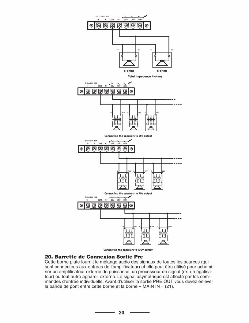
20. Barrette de Connexion Sortie Pre Cetteborneplatefournitlemélangeaudiodessignauxdetouteslessources(quisontconnectéesauxentréesdel’amplificateur)etellepeutêtreutilisépourachemi-nerunamplificateurexternedepuissance,unprocesseurdesignal(ex.unégalisa-teur)outoutautreappareilexterne.Lesignalasymétriqueestaffectéparlescom-mandesd’entréeindividuelle.Avantd’utiliserlasortiePREOUTvousdevezenleverlabandedepontentrecetteborneetlaborne«MAININ»(21).
COM 25V 70V 100V
DC 24V 15A
+ - 4Ω
8-ohms
Total Impedance 4-ohms
8-ohms
0 25V 0 25V 0 25V
COM 25V 70V 100V
DC 24V 15A
+ - 4Ω
Connecting the speakers to 25V output
0 70V 0 70V 0 70V
COM 25V 70V 100V
DC 24V 15A
+ - 4Ω
Connecting the speakers to 70V output
0 100V 0 100V 0 100V
COM 25V 70V 100V
DC 24V 15A
+ - 4Ω
Connecting the speakers to 100V output
21
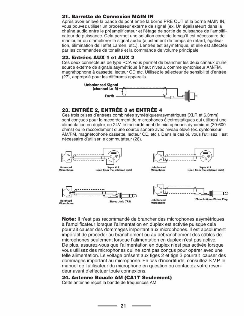
21. Barrette de Connexion MAIN IN AprèsavoirenlevélabandedepontentrelabornePREOUTetlaborneMAININ,vouspouvezutiliserunprocesseurexternedesignal(ex.Unégalisateur)danslachaîneaudioentrelepréamplificateuretl’étagedesortiedepuissancedel’amplifi-cateurdepuissance.Celapermetunesolutioncorrectelorsqu’ilestnécessairedemanipuleroud’améliorerlesignalaudio(ajustementdetempsderetard,égalisa-tion,éliminationdel’effetLarsen,etc.).L’entréeestasymétrique,etelleestaffectéeparlescommandesdetonalitéetlacommandedevolumeprincipale.
22. Entrées AUX 1 et AUX 2 CesdeuxconnecteursdetypeRCAvouspermetdebrancherlesdeuxcanauxd’unesourceexternedesignaleasymétriqueàhautniveau,commesyntoniseurAM/FM,magnétophoneàcassette,lecteurCDetc.Utilisezlesélecteurdesensibilitéd’entrée(27),appropriépourlesdifférentsappareils.
23. ENTRÉE 2, ENTRÉE 3 et ENTRÉE 4 Cestroisprisesd’entréescombinéessymétriques/asymétriques(XLRet6.3mm)sontconçuespourleraccordementdemicrophonesélectrostatiquesquiutilisentunealimentationenduplexde24V,leraccordementdemicrophonesdynamique(30-600ohms)ouleraccordementd’unesourcesonoreavecniveauélevé(ex.syntoniseurAM/FM,magnétophonecassette,lecteurCD,etc.).Danslecasoùvousl’utilisezilestnécessaired’utiliserlecommutateur(26).
Note: Iln’estpasrecommandédebrancherdesmicrophonesasymétriques àl’amplificateur lorsquel’alimentationenduplexestactivéepuisquecelapourraitcauserdesdommagesimportantauxmicrophones.Ilestabsolumentimpératifdeprocéderaubranchementouaudébranchementdescâblesdemicrophonesseulementlorsquel’alimentationenduplexn’estpasactivé.Deplus,assurez-vousquel’alimentationenduplexn’estpasactivéelorsquevousutilisezdesmicrophonesquinesontpasconçuspouropéreravecunetellealimentation.Levoltageprésentauxtiges2ettige3pourraitcauserdesdommagesimportantaumicrophone.Encasd’incertitude,consultezS.V.P.lemanueldel’utilisateurdumicrophoneenquestionoucontactezvotrereven-deuravantd’effectuertouteconnexions.24. Antenne Boucle AM (CA1T Seulement)CetteantennereçoitlabandedefréquencesAM.
3-pin XLR (seen from the soldered side)
BalancedMicrophone
123
3-pin XLR (seen from the soldered side)
UnbalancedMicrophone
123
Stereo Jack (TRS)BalancedMicrophone
UnbalancedMicrophone
1/4-inch Mono Phone Plug
RCA Plug
Unbalanced Signal(channel Lo R)
Earth
22
25. Antenne FM (CA1T Seulement) CetteantennereçoitlabandedefréquencesFM.
26. ENTRÉE 2, ENTRÉE 3 et ENTRÉE 4 Sensibilité d’entrée et Commutateur d’alimentation en duplex 24V sur prise XLR EnréglantcescommutateursàlapositionLINE,lesentrées2,3et4peuventêtreconnectéàunesourceaudioavecsignaldesortieàniveauélevé.EnréglantcescommutateursàlapositionMIClesentrées2,3et4peuventêtreconnectésàdesmicrophonesdynamiquesàbasseimpédance.Lorsquelecommutateurestrégléàlaposition24V,l’alimentationenduplex24Vestconnectéeauxtiges2et3delapriseXLRsurlesentrées2,3et4.Ceciestnécessairepourl’opérationdemicrophonesdetypeélectrolytiquesquirequièrentcetyped’alimentationexterne.Ilestrecommandéd’utilisercecommutateuraveclacommandedevolumeprincipalerégléeauniveauminimum.
27. Sélecteur de Sensibilité d’Entrée (AUX1, AUX2)Lorsquecesélecteurestàlaposition“1”lesentréesAUX1etAUX2peuventaccepterlessignauxdesortieprovenantdelecteurCD.Lorsquelesélecteurestàlaposition“2”lesentréesAUX1etAUX2peuventaccepterlessignauxdesortieprovenantderadioAM/FM.Lorsquecesélecteurestàlaposition“3”lesentréesAUX1etAUX2peuventaccepterlessignauxdesortieprovenantdemagnétophoneàcassette.Lors-quecesélecteurestàlaposition“4”lesentréesAUX1etAUX2peuventaccepterlessignauxdesortiedeniveauélevé.
28. Commande de Niveau d’Entrée Pour Dispositif de Recherche par Téléphone CettecommandevouspermetderéglerlevolumedusignaledesourceraccordéàlaborneTEL.Paging(29).Entournantlacommandedanslesenshorairevousaug-mentezlevolumedelasourcecorrespondante.Nousvousrecommandonsdegarderlacommandeàsonréglageminimumde“0”lorsqueledispositifderecherchen’estpasutilisé.
29. Entrée Dispositif de Recherche TEL. Labarrettedeconnexiond’entréevouspermetdeconnecterunsignaledetéléphone(600ohms).L’entréecomporteundispositifdePRIORITÉdeVOIX,quiétouffetousautressignauxd’entréeunefoisqu’unsignaldetéléphoneestdétecté.Sivousvoulezavoircettefonctiondésactivéedemanièrepermanente,entrezencontactavecuncentredeserviceYorkvilleSound.
30. Bornes “Priority” Lorsquevouscréezuncourt-circuitaveccesbornes(ex.Enutilisantuncommu-tateurélectrique),lessignauxaudioprovenantdesentréesAUX1,AUX2/TAPE,CASSETTEetTUNERsontatténuésalorsquelessignauxprovenantdesentréesINPUT1,INPUT2etINPUT4ontpriorité.
PRIORITY TEL. PAGING
T R+ - G
1W / 8Ω
AuxiliaryContact
23
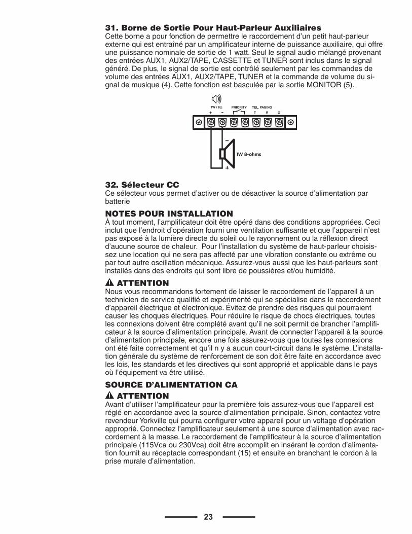
31. Borne de Sortie Pour Haut-Parleur Auxiliaires Cetteborneapourfonctiondepermettreleraccordementd’unpetithaut-parleurexternequiestentraînéparunamplificateurinternedepuissanceauxiliaire,quioffreunepuissancenominaledesortiede1watt.SeullesignalaudiomélangéprovenantdesentréesAUX1,AUX2/TAPE,CASSETTEetTUNERsontinclusdanslesignalgénéré.Deplus,lesignaldesortieestcontrôléseulementparlescommandesdevolumedesentréesAUX1,AUX2/TAPE,TUNERetlacommandedevolumedusi-gnaldemusique(4).CettefonctionestbasculéeparlasortieMONITOR(5).
32. Sélecteur CCCesélecteurvouspermetd’activeroudedésactiverlasourced’alimentationparbatterie
NOTES POUR INSTALLATION Àtoutmoment,l’amplificateurdoitêtreopérédansdesconditionsappropriées.Ceciinclutquel’endroitd’opérationfourniuneventilationsuffisanteetquel’appareiln’estpasexposéàlalumièredirectedusoleiloulerayonnementoularéflexiondirectd’aucunesourcedechaleur.Pourl’installationdusystèmedehaut-parleurchoisis-sezunelocationquineserapasaffectéparunevibrationconstanteouextrêmeoupartoutautreoscillationmécanique.Assurez-vousaussiqueleshaut-parleurssontinstallésdansdesendroitsquisontlibredepoussièreset/ouhumidité.
ATTENTIONNousvousrecommandonsfortementdelaisserleraccordementdel’appareilàuntechniciendeservicequalifiéetexpérimentéquisespécialisedansleraccordementd’appareilélectriqueetélectronique.Évitezdeprendredesrisquesquipourraientcauserleschoquesélectriques.Pourréduirelerisquedechocsélectriques,touteslesconnexionsdoiventêtrecomplétéavantqu’ilnesoitpermitdebrancherl’amplifi-cateuràlasourced’alimentationprincipale.Avantdeconnecterl’appareilàlasourced’alimentationprincipale,encoreunefoisassurez-vousquetouteslesconnexionsontétéfaitecorrectementetqu’ilnyaaucuncourt-circuitdanslesystème.L’installa-tiongénéraledusystèmederenforcementdesondoitêtrefaiteenaccordanceavecleslois,lesstandardsetlesdirectivesquisontappropriéetapplicabledanslepaysoùl’équipementvaêtreutilisé.
SOURCE D’ALIMENTATION CA ATTENTION
Avantd’utiliserl’amplificateurpourlapremièrefoisassurez-vousquel’appareilestrégléenaccordanceaveclasourced’alimentationprincipale.Sinon,contactezvotrerevendeurYorkvillequipourraconfigurervotreappareilpourunvoltaged’opérationapproprié.Connectezl’amplificateurseulementàunesourced’alimentationavecrac-cordementàlamasse.Leraccordementdel’amplificateuràlasourced’alimentationprincipale(115Vcaou230Vca)doitêtreaccompliteninsérantlecordond’alimenta-tionfournitauréceptaclecorrespondant(15)etensuiteenbranchantlecordonàlaprisemuraled’alimentation.
PRIORITY TEL. PAGING
T R+ - G
1W / 8Ω
1W 8-ohms
24
BLOC D’ALIMENTATION CC ATTENTION
Lasourced’alimentation24VCC(ex.unebatterie)doitêtreconnectéeauxbornes(18)quisontcouverteparuncouvercleprotecteur.Pourréduirelerisquedediminutiondevoltageàunminimumetpouréliminerlerisqued’endommagerlescâblesdebatterieparunesurchargethermique,cescâblesdoiventavoirchacunundiamètreminimumde2.5mm2.Lamiseenmarchedel’appareilestfaitàl’aideducommutateurdemiseenmarche(33).
BRANCHEMENT DES BORNES DE SORTIE ATTENTION
Pouréviterlesrisquesdechocsélectriques,ne touchez jamaislabarrettedeconnexionquiaboutitauxbornesdesortiedel’amplificateurlorsdel’opération.Souslasectionfigures,vousverrezlesconnexionspossiblesdebornesdeSORTIEdehaut-parleuraccessibleenenlevantlecouverclepro-tecteur.Considérezlesrèglessuivantes:
Impédance de ligne constante•L’impédancetotaldeshaut-parleursconnectésdoit corresponde à celle sélectionnée sur les bornes de sortie de l’amplificateur.•Lasommedelacapacitédepuissancedeshaut-parleursnedoitpasêtreplusbassequelacapa-citédepuissancedel’amplificateur.•Lalongueurdescâblesservantauraccordementdoitêtregardéaussicourtequepossible;danstouslescas,plusladistanceàcouvrirestgrandepluslasectiontransversaledescâblesdoitêtregrande.
Lignes de voltage constante •Chaquehaut-parleurdoitêtreéquipéd’untransformateurdeligneavecunvoltaged’entréeégaleauvoltagedeligne(25,70,100V).•Lasommedelacapacitédepuissancedeshaut-parleursne doit pas excéder la capacité de puissance de sortie de l’amplificateur(ex. la capacité de consommation totale des haut-parleurs installé dans les zones 1 à 4).
25
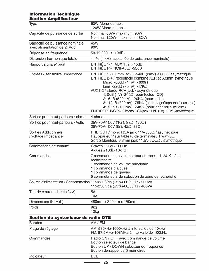
Information TechniqueSection Amplificateur Type 60W-Mono-detable 120W-Mono-detable
Capacitédepuissancedesortie Nominal:60W-maximum:90W Nominal:120W-maximum:18OW
Capacitédepuissancenominale 45Wavecalimentationde24Vdc 90W
Réponseenfréquence 50-15,000Hz(±3dB)
Distorsionharmoniquetotale ≤1%(1kHz-capacitéedepuissancenominale)
Rapportsignale/bruit ENTRÉE1-4,AUX1,2:>45dB ENTRÉEPRINCIPALE:>55dB
Entrées/sensibilité,impédance ENTRÉE1/6.3mmjack/-54dB(2mV)-300Ω/asymétrique ENTRÉE2-4/réceptaclecombinéXLRet6.3mmsymétrique Micro:-60dB(1mV)-600Ω Line:-22dB(75mV)-47KΩ AUX1-2/stéréoRCAjack/asymétrique 1:0dB(1V)-240Ω(pourlecteurCD) 2:-6dB(500mV)-120KΩ(pourradio) 3:-10dB(300mV)-75KΩ(pourmagnétophoneàcassette) 4:-20dB(100mV)-24KΩ(pourappareilauxiliaire) ENTRÉEPRINCIPALE/monoRCAjack10dB(1V)-1OKΩ/asymétrique
Sortiespourhaut-parleurs/ohms 4ohms
Sortiespourhaut-parleurs/Volts 25V-70V-100V(10Ω,83Ω,170Ω) 25V-70V-100V(5Ω,42Ω,83Ω)
SortiesAdditionnels PREOUT/monoRCAjack/1V-600Ω/asymétrique/voltageimpédance Haut-parleur/surtableaudeterminale/1watt-8Ω SortieMoniteur/6.3mmjack/1.5V-6OOΩ/symétrique
Commandesdetonalité Graves±10dB-100Hz Aiguës±10dB-10kHz
Commandes 7commandesdevolumepourentrées1-4,AUX1-2et recherchetel. 1commandedevolumeprincipale 1commanded’aiguës 1commandedegraves 5commutateursdesélectiondezonederecherche
Sourced’alimentation/Consommation115/230Vca(±5%)-60/50Hz/200VA 115/230Vca(±5%)-60/50Hz/400VA
Tiredecourantdirect(24V) 5A 10A
Dimensions(PxHxL) 480mmx320mmx150mm
Poids 9kg 12kg
Section de syntoniseur de radio DTS Bandes AM/FM
Plagederéglage AM:530kHz-1600kHzàintervallesde10kHz FM:87.5MHz-108MHzàintervallede100kHz
Commandes RadioON/OFFaveccommandedevolume Boutonsélecteurdebande BoutonUP/DOWNsélecteurdefréquence Boutonderappelde5mémoires
Indicateur DCL
26
Exemple de connexions possibles
CA1TPROFESSIONAL PUBLIC ADDRESS POWER AMPLIFIER
CHANNEL 1 CHANNEL 2 CHANNEL 3 CHANNEL 4 CHANNEL 5 CHANNEL 6HEADPHONE
OUTPUT
BASS TREBLE
MASTERPAGING SELECTION
ZONE 1 ZONE 2 ZONE 3 ZONE 4 ALL
MUTEINPUTPOWER
Peak / Limiter
ON
OFF
OUTPUTLEVEL
C O L I S E U M
10
9
82
1
73
0
654
10
9
82
1
73
0
654
10
9
82
1
73
0
654
10
9
82
1
73
0
654
10
9
82
1
73
0
654
10
9
82
1
73
0
654
10982
1
73
0
654
10982
1
73
0
654
10
9
82
1
73
0
65
4PLL AM/FM RADIO
M1 M2 M3 M4 M5 MEMORY DOWN
UP
AM/FM
VOL
Microphone
MicrophoneStand
Headphones
CA1PROFESSIONAL PUBLIC ADDRESS POWER AMPLIFIER
CHANNEL 1 CHANNEL 2 CHANNEL 3 CHANNEL 4 CHANNEL 5 CHANNEL 6HEADPHONE
OUTPUT
BASS TREBLE
MASTERPAGING SELECTION
ZONE 1 ZONE 2 ZONE 3 ZONE 4 ALL
MUTEINPUTPOWER
Peak / Limiter
ON
OFF
OUTPUTLEVEL
C O L I S E U M
10
9
82
1
73
0
654
10
9
82
1
73
0
654
10
9
82
1
73
0
654
10
9
82
1
73
0
654
10
9
82
1
73
0
654
10
9
82
1
73
0
654
10982
1
73
0
654
10982
1
73
0
654
10
9
82
1
73
0
65
4
Microphone
MicrophoneStand
Headphones
27
DC POWER PRIORITY
COM
ON OFF
COM
MAININ
PREOUT
TEL VOLUME
1 42 3
1: CD PLAYER
4: AUX IN
CHANNEL 6INPUT
L
R
L
RCHANNEL 5
INPUTCHANNEL 4INPUT
CHANNEL 3INPUT
CHANNEL 2INPUT
MIC
LINE 24V
MIC
LINE 24V
MIC
LINE 24V
AUX 2 AUX 1
2: AM/FM RADIO3: CASSETTE PLAYER
1 42 3
COM COM Zone 4 Zone 3 Zone 2 Zone 1
25V 70V 100V
DC 24V 15A
TEL. PAGING
T R+ -
+ -
G
1W / 8Ω
4Ω
GND
C O L I S E U MPROFESSIONAL PUBLIC ADDRESS POWER AMPLIFIER
FUSE: T 5,0 A
CA
UT
ION
: RE
PL
AC
E W
ITH
SA
ME
TY
PE
FU
SE
AN
D R
AT
ING
AT
TE
NT
ION
: U
TIL
ISE
R U
N F
US
IBL
E D
ER
EC
HA
NG
E D
E M
EM
E T
YP
E E
T C
AL
IBR
E
DESIGNED & MANUFACTURED FOR YORKVILLE SOUND • TORONTO, CANADA
z515/1b5
230V 50Hz 1,3A
DC 24V 15A
120VAC 60Hz 2.6A
NTR
L Listed
AM LOOP
FMANTENNA
MicrophoneCD Player
AM/FM Tuner
Cassette Recorder
MicrophoneStand
24 V
CD Player
AM/FM Tuner
Cassette RecorderContact
“Voice Priority”
Telephony
Mains
Battery
Horn Speaker Speaker
Sound Column
Power Amplif ier
Equalizer

U.S.A.
Yorkville Sound Inc.4625 Witmer Industrial Estate
Niagara Falls, New York14305 USA
Voice: (716) 297-2920Fax: (716) 297-3689
WORLD HEADQUARTERSCANADA
Yorkville Sound550 Granite CourtPickering, Ontario
L1W-3Y8 CANADA
Voice: (905) 837-8481Fax: (905) 837-8746
Printed in China
Manual-Owners-CA1-CA1T-00-2v1•Jan3/2011