Embed Size (px)
Citation preview
Copyright © 2014 John Wiley & Sons, Inc. All rights reserved.
Chapter 4DC Machines
Third Edition
P. C. Sen
Principles of Electric Machines
and
Power Electronics
Copyright © 2014 John Wiley & Sons, Inc. All rights reserved.Fig_1-1
Chapter 4 DC machine
•Electric machine Type: rotating machine
Applications: generator (electric source)
motor (electric load)
•Main contentsIntroduction of electric machines
DC machine basics
Armature winding
Armature voltage
Electromagnetic torque
Magnetization (saturation) curve
DC machine classifications
Copyright © 2014 John Wiley & Sons, Inc. All rights reserved.
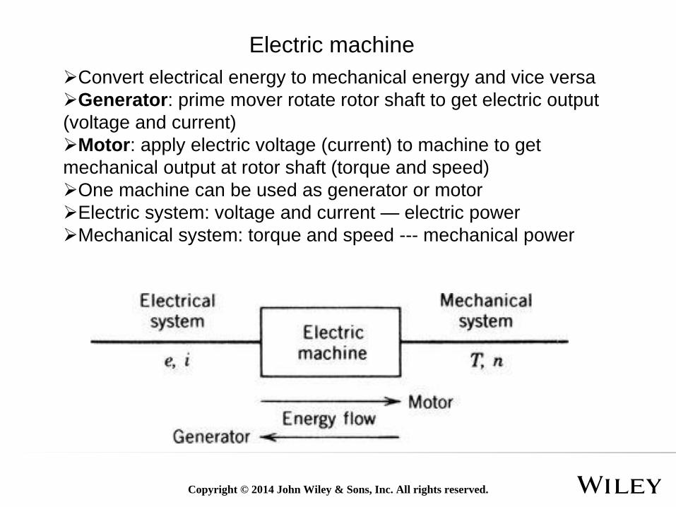
Convert electrical energy to mechanical energy and vice versa
Generator: prime mover rotate rotor shaft to get electric output
(voltage and current)
Motor: apply electric voltage (current) to machine to get
mechanical output at rotor shaft (torque and speed)
One machine can be used as generator or motor
Electric system: voltage and current — electric power
Mechanical system: torque and speed --- mechanical power
Electric machine
Copyright © 2014 John Wiley & Sons, Inc. All rights reserved.
Machine types
•DC machineUse or generate DC power
Applications: Automobile(Air condition, oil pump), robots, power
tool
•AC synchronous machineUse or generate AC power
Rotational speed is the same with the electrical speed
Applications: power generator, house hold appliances, Electrical
vehicle
•Induction machine (Asynchronous machine)Use or generate AC power
Rotational speed is slower than electrical speed
Applications: house hold appliances, Electrical vehicle
Copyright © 2014 John Wiley & Sons, Inc. All rights reserved.
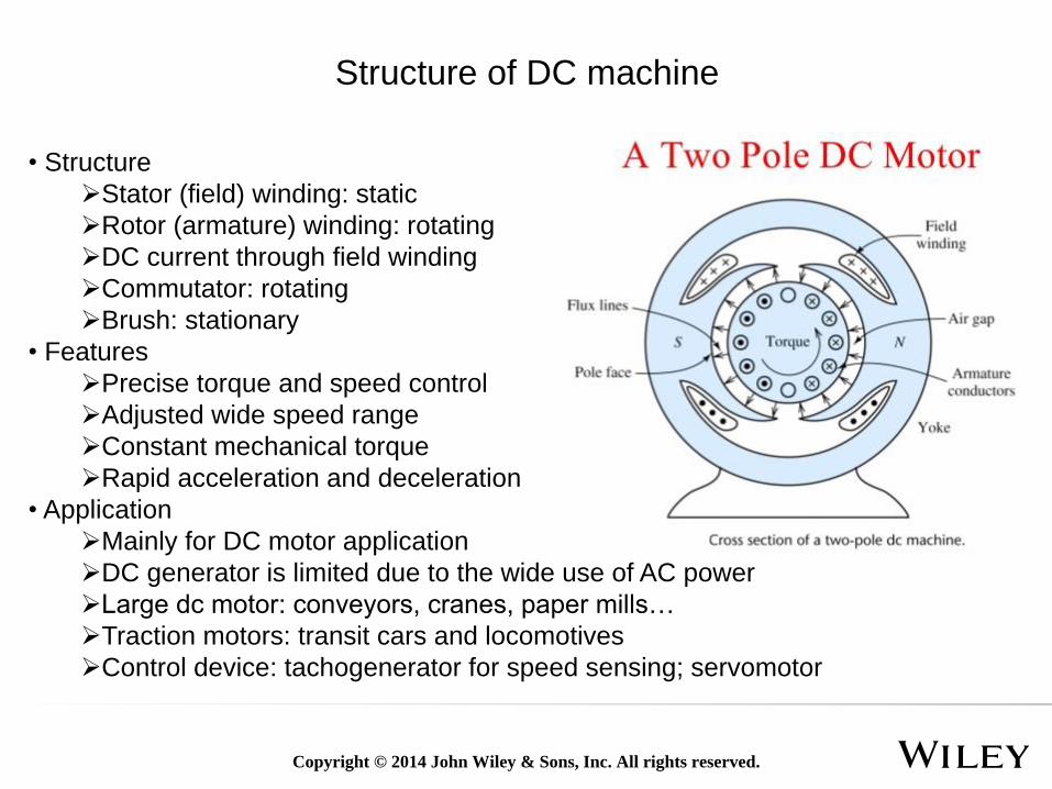
• Structure
Stator (field) winding: static
Rotor (armature) winding: rotating
DC current through field winding
Commutator: rotating
Brush: stationary
• Features
Precise torque and speed control
Adjusted wide speed range
Constant mechanical torque
Rapid acceleration and deceleration
• Application
Mainly for DC motor application
DC generator is limited due to the wide use of AC power
Large dc motor: conveyors, cranes, paper mills…
Traction motors: transit cars and locomotives
Control device: tachogenerator for speed sensing; servomotor
Structure of DC machine
Copyright © 2014 John Wiley & Sons, Inc. All rights reserved.
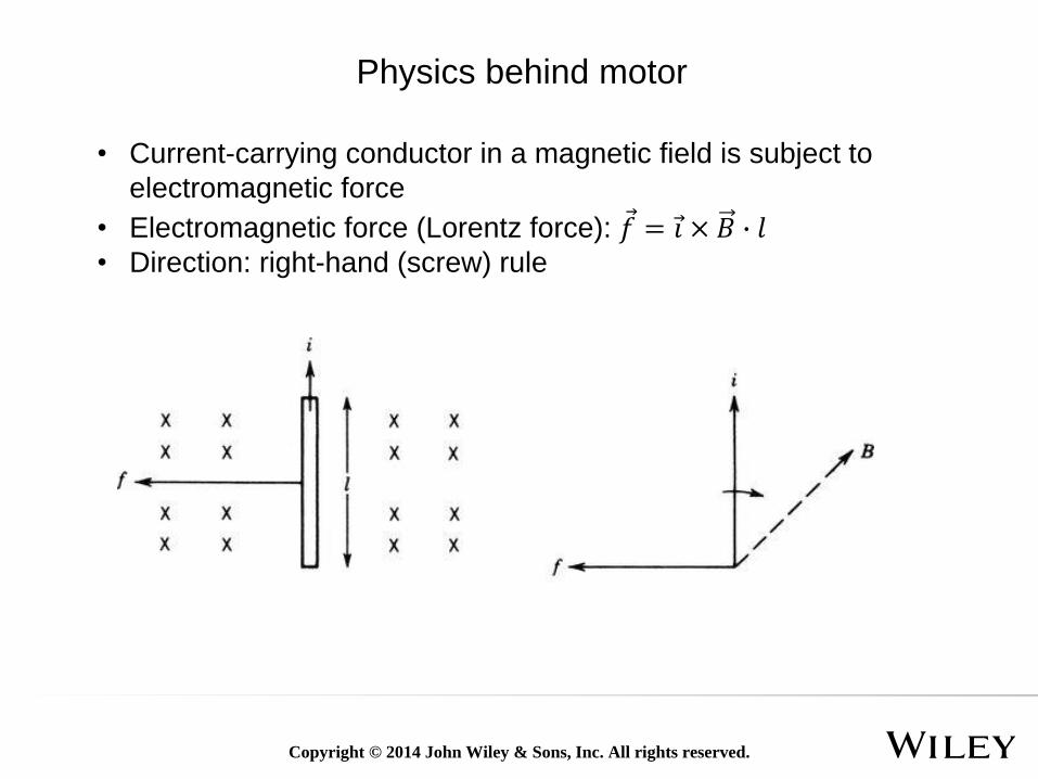
• Current-carrying conductor in a magnetic field is subject to
electromagnetic force
• Electromagnetic force (Lorentz force): Ԧ𝑓 = Ԧ𝑖 × 𝐵 ∙ 𝑙• Direction: right-hand (screw) rule
Physics behind motor
Copyright © 2014 John Wiley & Sons, Inc. All rights reserved.
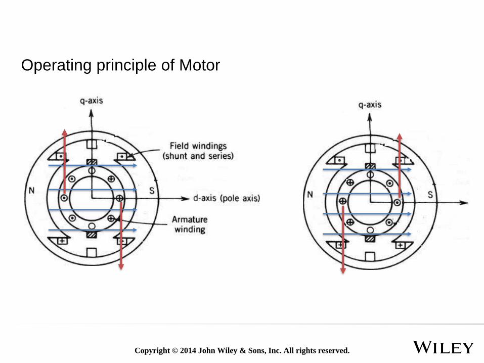
Operating principle of Motor

Copyright © 2014 John Wiley & Sons, Inc. All rights reserved.
Operating principle of Motor- commuter and brush
Copyright © 2014 John Wiley & Sons, Inc. All rights reserved.
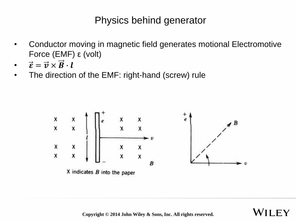
• Conductor moving in magnetic field generates motional Electromotive
Force (EMF) ε (volt)
• 𝜺 = 𝒗 × 𝑩 ∙ 𝒍• The direction of the EMF: right-hand (screw) rule
Physics behind generator
Copyright © 2014 John Wiley & Sons, Inc. All rights reserved.
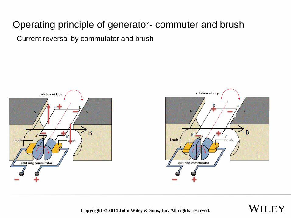
Operating principle of generator- commuter and brush
Current reversal by commutator and brush
Copyright © 2014 John Wiley & Sons, Inc. All rights reserved.
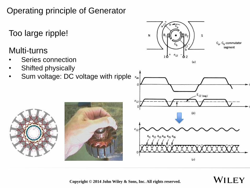
Multi-turns• Series connection
• Shifted physically
• Sum voltage: DC voltage with ripple
Too large ripple!
Operating principle of Generator
Copyright © 2014 John Wiley & Sons, Inc. All rights reserved.
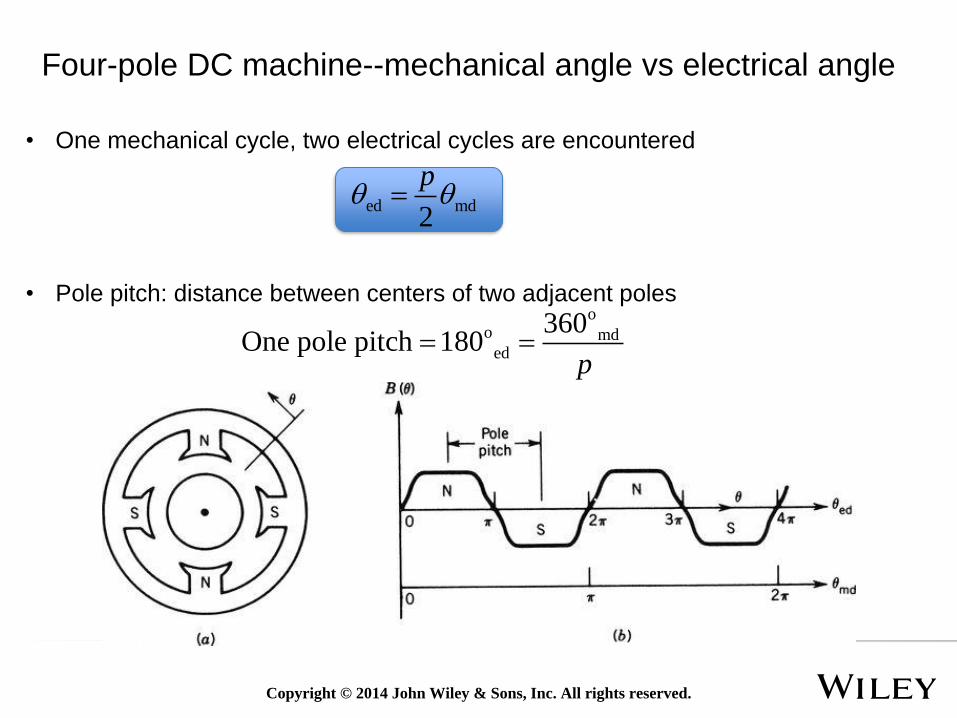
Four-pole DC machine--mechanical angle vs electrical angle
ed md2
p
oo md
ed
360One pole pitch 180
p
• Pole pitch: distance between centers of two adjacent poles
• One mechanical cycle, two electrical cycles are encountered
Copyright © 2014 John Wiley & Sons, Inc. All rights reserved.
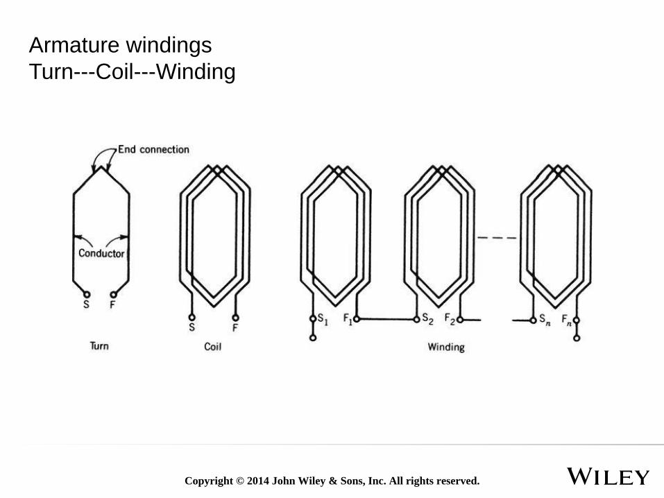
Armature windings
Turn---Coil---Winding
Copyright © 2014 John Wiley & Sons, Inc. All rights reserved.
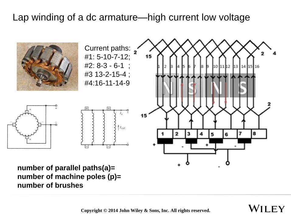
Lap winding of a dc armature—high current low voltage
number of parallel paths(a)=
number of machine poles (p)=
number of brushes
Current paths:
#1: 5-10-7-12;
#2: 8-3 - 6-1 ;
#3 13-2-15-4 ;
#4:16-11-14-9
Copyright © 2014 John Wiley & Sons, Inc. All rights reserved.
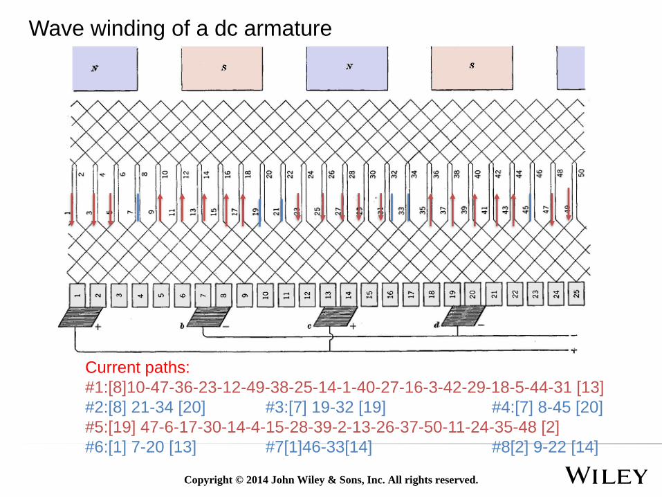
Current paths:
#1:[8]10-47-36-23-12-49-38-25-14-1-40-27-16-3-42-29-18-5-44-31 [13]
#2:[8] 21-34 [20] #3:[7] 19-32 [19] #4:[7] 8-45 [20]
#5:[19] 47-6-17-30-14-4-15-28-39-2-13-26-37-50-11-24-35-48 [2]
#6:[1] 7-20 [13] #7[1]46-33[14] #8[2] 9-22 [14]
Wave winding of a dc armature
Copyright © 2014 John Wiley & Sons, Inc. All rights reserved.
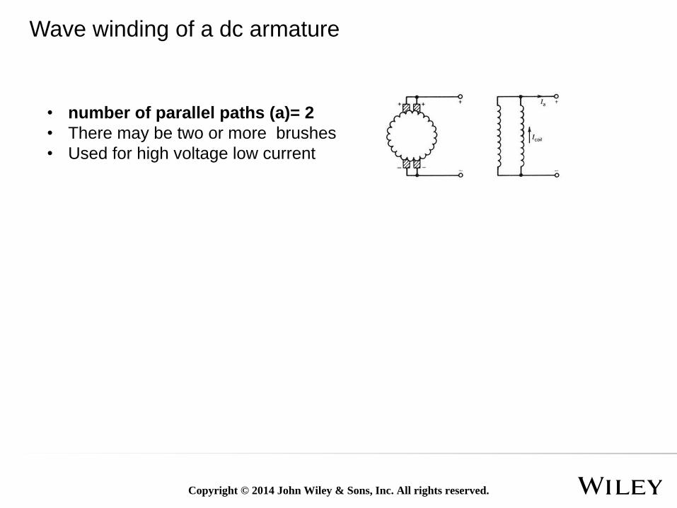
• number of parallel paths (a)= 2
• There may be two or more brushes
• Used for high voltage low current
Wave winding of a dc armature
Copyright © 2014 John Wiley & Sons, Inc. All rights reserved.
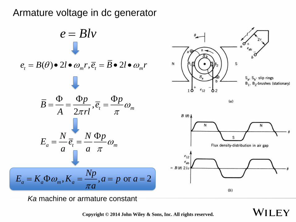
Armature voltage in dc generator
e Blv
( ) 2 , 2t m t me B l r e B l r
,2
t m
p pB e
A rl
a t m
N N pE e
a a
, , or 2a a m a
NpE K K a p a
a
Ka machine or armature constant
Copyright © 2014 John Wiley & Sons, Inc. All rights reserved.
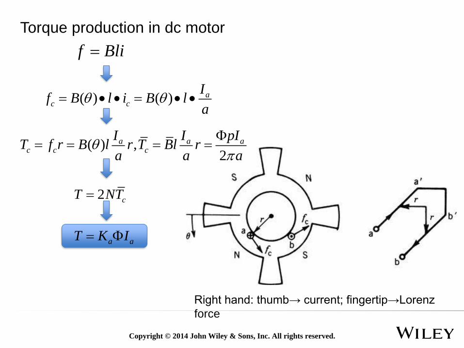
Torque production in dc motor
Right hand: thumb→ current; fingertip→Lorenz
force
f Bli
( ) ( ) ac c
If B l i B l
a
( ) ,2
a a ac c c
I I pIT f r B l r T Bl r
a a a
2 cT NT
a aT K I
Copyright © 2014 John Wiley & Sons, Inc. All rights reserved.
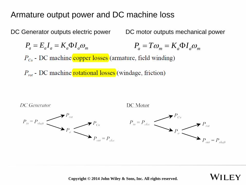
Armature output power and DC machine loss
a m a a mP T K I a a a a a mP E I K I
DC Generator outputs electric power DC motor outputs mechanical power
Copyright © 2014 John Wiley & Sons, Inc. All rights reserved.
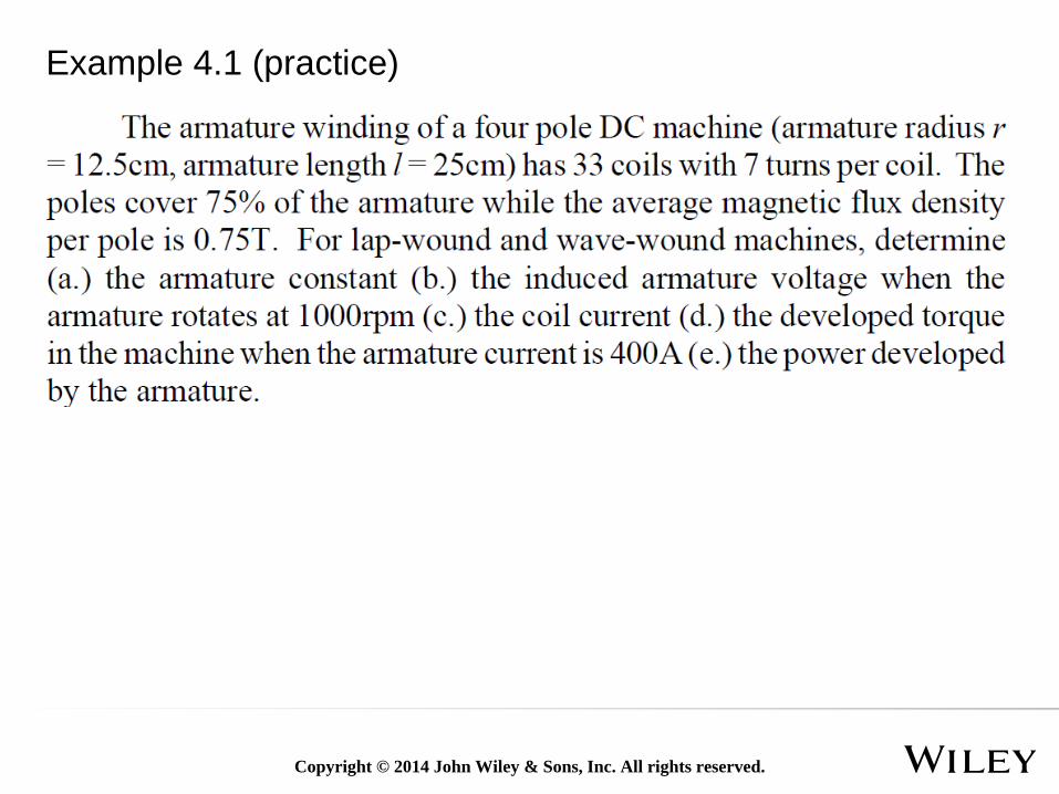
Example 4.1 (practice)
Copyright © 2014 John Wiley & Sons, Inc. All rights reserved.
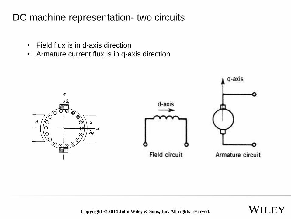
DC machine representation- two circuits
• Field flux is in d-axis direction
• Armature current flux is in q-axis direction
Copyright © 2014 John Wiley & Sons, Inc. All rights reserved.
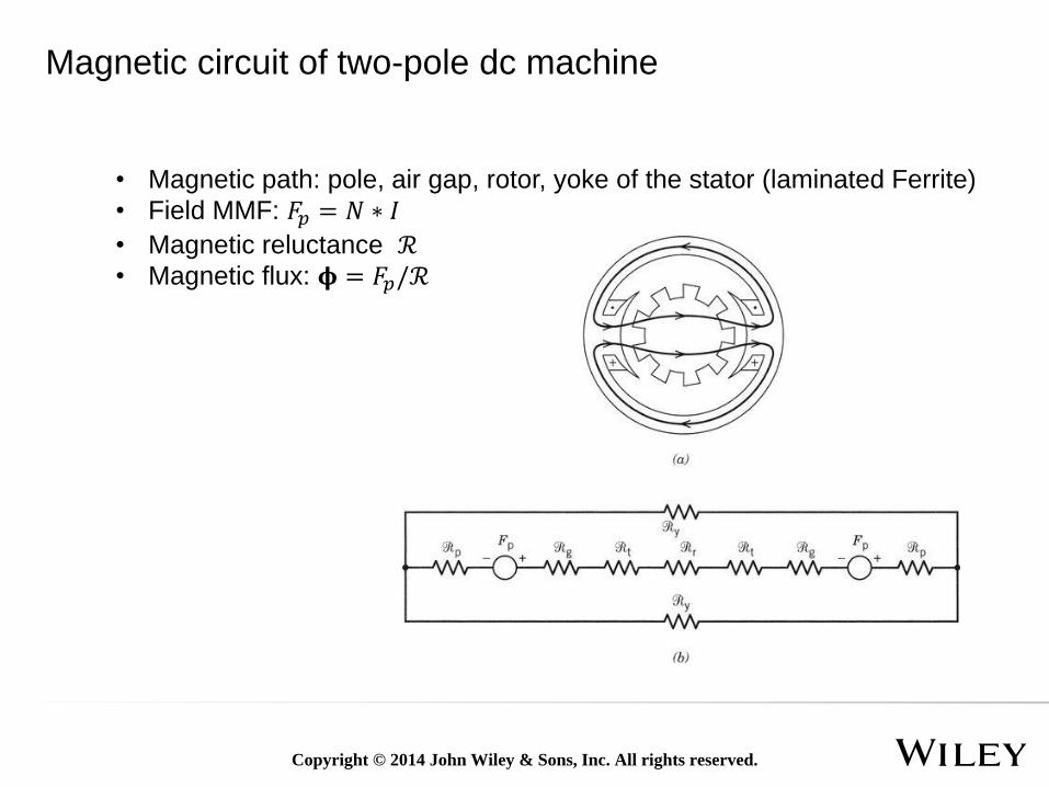
Magnetic circuit of two-pole dc machine
• Magnetic path: pole, air gap, rotor, yoke of the stator (laminated Ferrite)
• Field MMF: 𝐹𝑝 = 𝑁 ∗ 𝐼
• Magnetic reluctance ℛ• Magnetic flux: 𝛟 = 𝐹𝑝/ℛ
Copyright © 2014 John Wiley & Sons, Inc. All rights reserved.
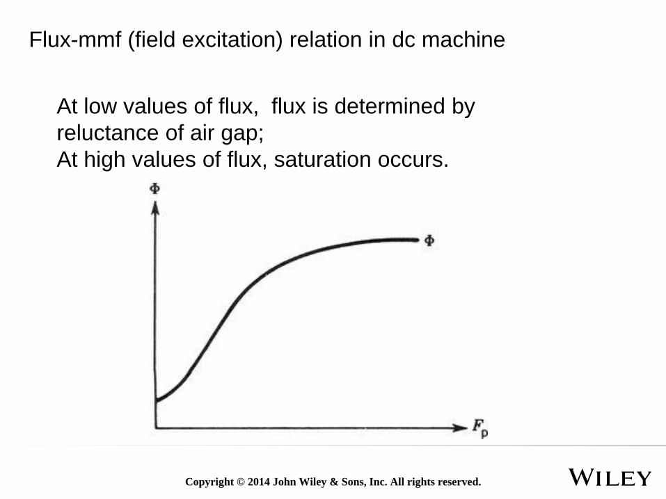
Flux-mmf (field excitation) relation in dc machine
At low values of flux, flux is determined by
reluctance of air gap;
At high values of flux, saturation occurs.
Copyright © 2014 John Wiley & Sons, Inc. All rights reserved.
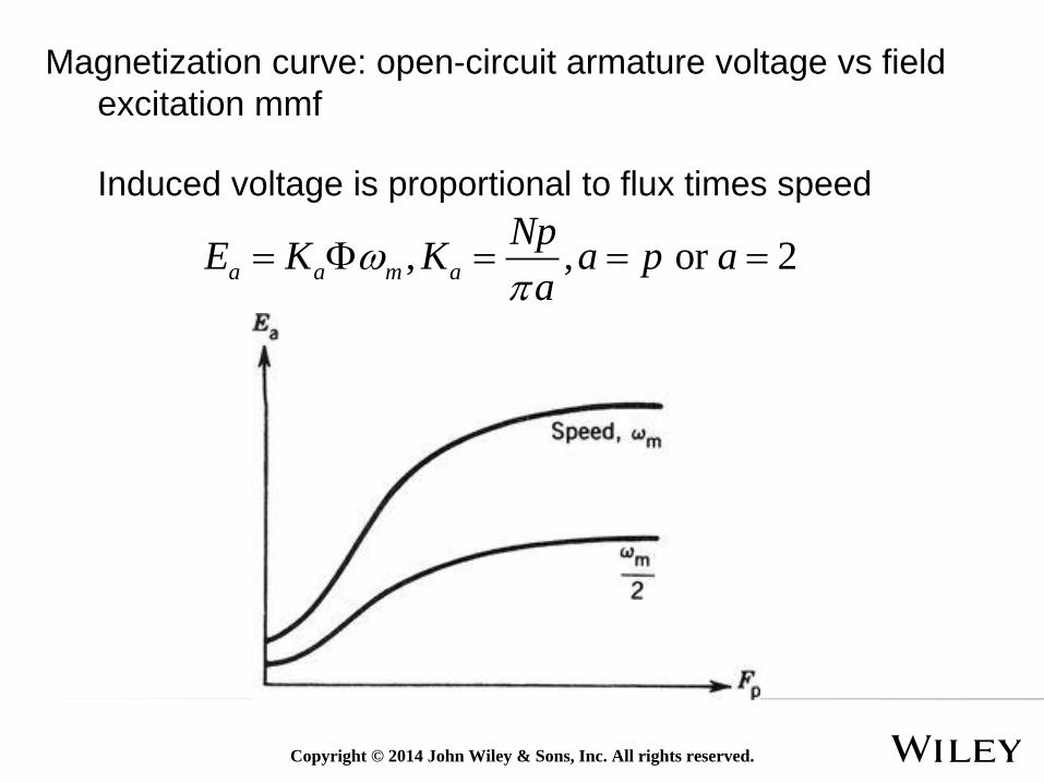
Magnetization curve: open-circuit armature voltage vs field
excitation mmf
Induced voltage is proportional to flux times speed
, , or 2a a m a
NpE K K a p a
a