Embed Size (px)
Citation preview
7/27/2019 AC Electric Machines Lab manul
http://slidepdf.com/reader/full/ac-electric-machines-lab-manul 1/98
ELECTRICAL MACHINES LAB.
LAB SAFETY RULES:
Read ALL of the following rules carefully and remember them while working in the
laboratory.
1. Some of the experiments involve voltages that could conceivably lead to
serious injury or death. Therefore strict adherence to the following rules
will greatly decrease the probability that accidents will occur.
2. Never hurry. Haste causes many accidents.
3. Use one hand to make connections
4. Always see that power is connected to your equipment through a circuit
breaker or load switch.
5. Connect the power source last. Disconnect the power source first.
6. Never make wiring changes on live circuits. Work deliberately and carefully
and check your work as you proceed.
7. Before connecting the power, check the wiring carefully for agreement with
the wiring diagram for an accidental short-circuit and for loose connections.
8. Check out the supply voltage to make sure that is what you expect. For
example: AC or DC, 120V, 208V or 240V.
9. Do not cause short-circuits or high currents arcs. Burn from arcs may be
very severe even at a distance of a few meters. Report all electrical burns to
your instructor.
10. Be careful to keep metallic accessories of apparel or jewelry out of contact
with live circuit parts and loose articles of clothing out of moving
machinery.
11. When using a multiple range meter always use the high range first, to
determine the feasibility of using a lower range.
12. Check the current rating of all rheostats before use. Make sure that nocurrent overload will occur as the rheostat setting is changed.
13. Never overload any electrical machinery by more than 25% of the rated
voltage or current for more than a few seconds.
14. Select ratings of a current coil (CC) and potential coil (PC) in a wattmeter
properly before connecting in a test circuit.
15. Do not permit a hot leg of a three phase 208V supply, or of a 240V or 120V
supply to come in contact with any grounded objects, as a dangerous short-
circuits will result.16. If you know or suspect that an accident is about to occur, take
immediate steps to prevent it but do not jeopardize your own safety indoing so.
7/27/2019 AC Electric Machines Lab manul
http://slidepdf.com/reader/full/ac-electric-machines-lab-manul 2/98
LIST OF EXPERIMENTS:
Sr.
No.Name of Experiment
Page
No:
1- Open Circuit Test of Transformer. 01
2- Short Circuit Test of Transformer. 06
3 Transformer Efficiency. 09
4 Direction of Rotation of 3-Phase Induction Motor. 15
5 Starting Characteristics of Squirrel Cage Induction Motor. 20
6 Running Characteristics of Squirrel Cage Induction Motor. 24
7 Starting Characteristics of Wound Rotor Induction Motors. 31
8 Speed Control of Wound Rotor Induction Motors. 35
9 Losses & Efficiency of Induction Motors. 40
10 Saturation Curve of an Alternator. 46
11 Effect of Speed on an Alternator. 52
12 Load Characteristics of an Alternator. 56
13 Losses & Efficiency of Alternators. 62
14 Paralleling Alternators. 70
15 Starting & Synchronizing, Synchronous Machines. 80
16 Synchronous Moto V-Curves. 86
17 Power Factor Correction Using Synchronous Motors. 91
7/27/2019 AC Electric Machines Lab manul
http://slidepdf.com/reader/full/ac-electric-machines-lab-manul 3/98
Lab Manual—EE-314—AC-Machines
University College of Engineering & Technology, IUB υ
EXPERIMENT # 1:
OPEN CIRCUIT TEST OF TRANSFORMER.
PERFORMANCE OBJECTIVE:
After completion of this laboratory experiment, the student will be able to perform an open circuit
transformer test,
• Measure the exciting current and determine the core losses in a transformer.
• Specifically, the student will be able to determine the Equivalent Circuit parameters (shunt branch) of
the transformer.
DISCUSSION:
The current input to the primary winding, without a load connected to the secondary winding
is usually from 1 to 5 percent of the full load current rating. This no load primary current is called the
exciting current and consist of the following:
1. The magnetizing current that supplies the alternating flux in the core, which produces the
primary and secondary induced voltages. This current component lags the applied voltage by
90°.
2. Due to eddy currents and hysteresis, the core will lose power. The changing flux induces
voltage and current in the iron core causing an I²R loss. This eddy current loss is minimized by
laminating the core and insulating each lamination with a varnish or oxide coating. The
inability of the magnetic domains of the core material to instantly follow the changing flux
(due to inter-domain friction) incurs a power loss as heat. This hysteresis loop loss is
minimized by the use of special steel and various core configurations. The lost core current is
in phase with the applied voltage.
The vectorial sum of the in-phase core loss and lagging magnetizing currents produces the
exciting current of a transformer.
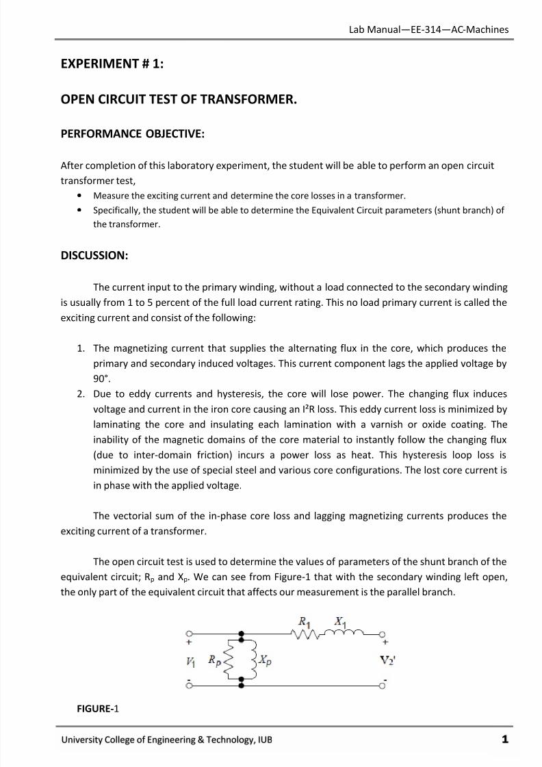
The open circuit test is used to determine the values of parameters of the shunt branch of the
equivalent circuit; Rp and Xp. We can see from Figure-1 that with the secondary winding left open,
the only part of the equivalent circuit that affects our measurement is the parallel branch.
FIGURE-1
7/27/2019 AC Electric Machines Lab manul
http://slidepdf.com/reader/full/ac-electric-machines-lab-manul 4/98
Lab Manual—EE-314—AC-Machines
University College of Engineering & Technology, IUB φ
EQUIPMENT:
• Single Phase Transformer [MV-1911]
• AC Power Meter [Goodwill Instek]
• Power Pack [MV-1300]
• Connecting Wires
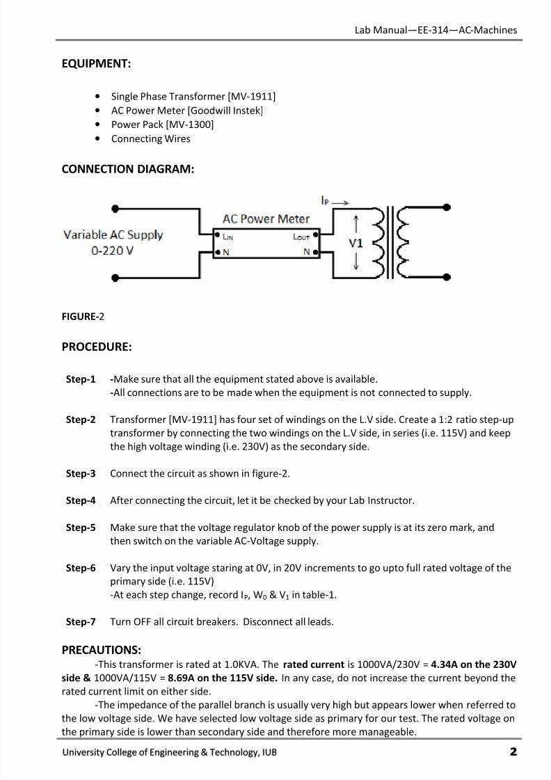
CONNECTION DIAGRAM:
FIGURE-2
PROCEDURE:
Step-1 -Make sure that all the equipment stated above is available.
-All connections are to be made when the equipment is not connected to supply.
Step-2 Transformer [MV-1911] has four set of windings on the L.V side. Create a 1:2 ratio step-up
transformer by connecting the two windings on the L.V side, in series (i.e. 115V) and keep
the high voltage winding (i.e. 230V) as the secondary side.
Step-3 Connect the circuit as shown in figure-2.
Step-4 After connecting the circuit, let it be checked by your Lab Instructor.
Step-5 Make sure that the voltage regulator knob of the power supply is at its zero mark, and
then switch on the variable AC-Voltage supply.
Step-6 Vary the input voltage staring at 0V, in 20V increments to go upto full rated voltage of the
primary side (i.e. 115V)
-At each step change, record IP, W0 & V1 in table-1.
Step-7 Turn OFF all circuit breakers. Disconnect all leads.
PRECAUTIONS:-This transformer is rated at 1.0KVA. The rated current is 1000VA/230V = 4.34A on the 230V
side & 1000VA/115V = 8.69A on the 115V side. In any case, do not increase the current beyond the
rated current limit on either side.
-The impedance of the parallel branch is usually very high but appears lower when referred to
the low voltage side. We have selected low voltage side as primary for our test. The rated voltage on
the primary side is lower than secondary side and therefore more manageable.
7/27/2019 AC Electric Machines Lab manul
http://slidepdf.com/reader/full/ac-electric-machines-lab-manul 5/98
Lab Manual—EE-314—AC-Machines
University College of Engineering & Technology, IUB χ
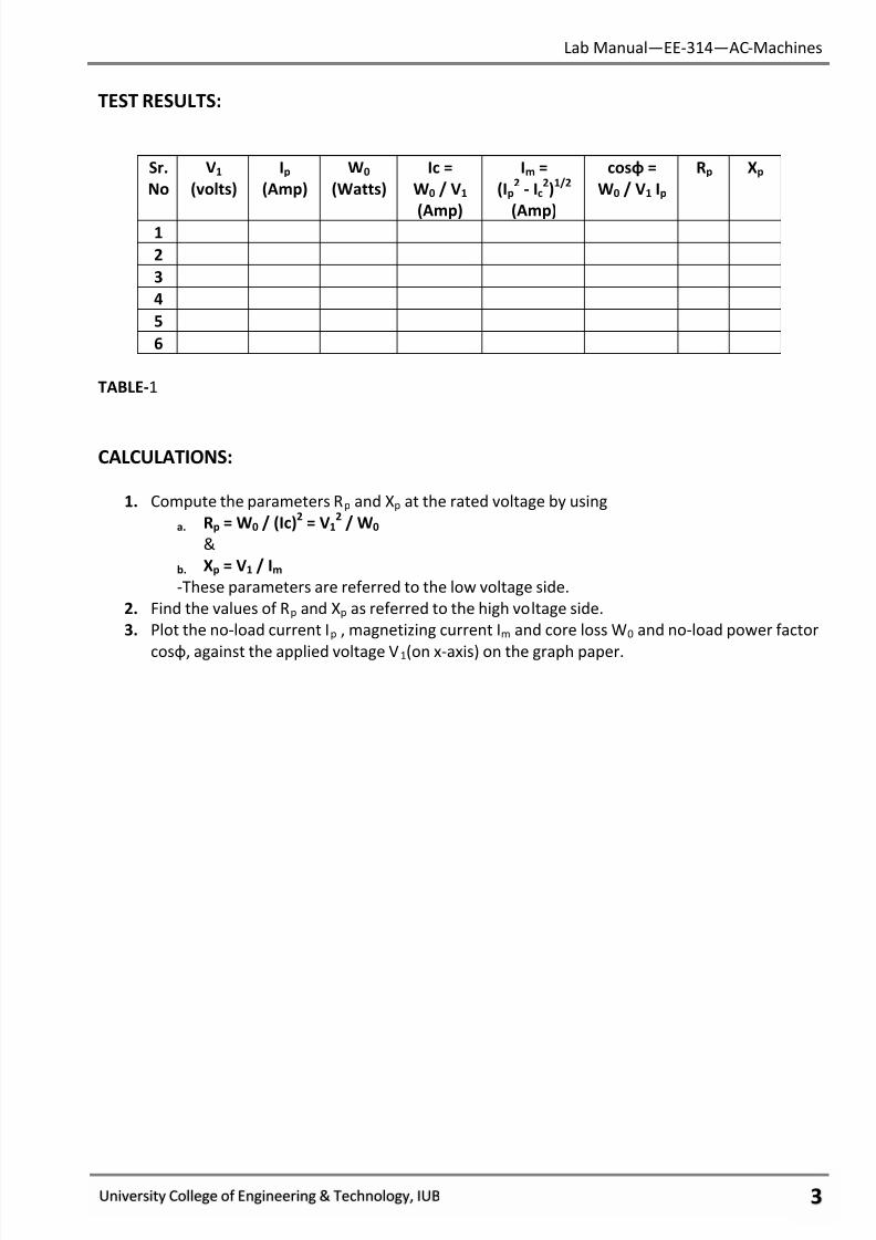
TEST RESULTS:
Sr.
No
V1
(volts)
Ip
(Amp)
W0
(Watts)
Ic =
W0 / V1
(Amp)
Im =
(Ip2
- Ic2)
1/2
(Amp)
cosφ =
W0 / V1 Ip
Rp Xp
1
2
3
4
5
6
TABLE-1
CALCULATIONS:
1. Compute the parameters Rp and Xp at the rated voltage by using
a. Rp = W0 / (Ic)2
= V12
/ W0
&
b. Xp = V1 / Im
-These parameters are referred to the low voltage side.
2. Find the values of Rp and Xp as referred to the high voltage side.
3. Plot the no-load current Ip , magnetizing current Im and core loss W0 and no-load power factor
cosφ, against the applied voltage V1(on x-axis) on the graph paper.

7/27/2019 AC Electric Machines Lab manul
http://slidepdf.com/reader/full/ac-electric-machines-lab-manul 6/98
Lab Manual—EE-314—AC-Machines
University College of Engineering & Technology, IUB ψ
GRAPH:

7/27/2019 AC Electric Machines Lab manul
http://slidepdf.com/reader/full/ac-electric-machines-lab-manul 7/98
Lab Manual—EE-314—AC-Machines
University College of Engineering & Technology, IUB ω
REVIEW QUESTIONS:
1. The current that produces the primary and secondary induced voltage in the core.
a. Lags the applied voltage by 90°.
b. Leads the applied voltage by 90°.
c. Is in phase with applied voltage.
2. Why does the core lose power?
____________________________________________________________________________
____________________________________________________________________________
____________________________________________________________________________
3. How can you minimize the losses in the core?
____________________________________________________________________________
____________________________________________________________________________
____________________________________________________________________________
FINAL CHECKLIST:
1. Clean your equipment/materials and work benches before you leave.
2. Return all equipment and materials to their proper storage area.
3. Submit your answers to the questions, together with your data, calculations, and results
before the next laboratory session.
____________
Signature:
Lab Instructor
7/27/2019 AC Electric Machines Lab manul
http://slidepdf.com/reader/full/ac-electric-machines-lab-manul 8/98
Lab Manual—EE-314—AC-Machines
University College of Engineering & Technology, IUB ϊ
EXPERIMENT # 2:
SHORT CIRCUIT TEST OF TRANSFORMER
PERFORMANCE OBJECTIVES:
Upon successful completion of this laboratory experiment, the student will be able to perform
a short circuit transformer test. Specifically, he will be able to determine the equivalent circuit
parameters (series branch) of a transformer by the short circuit method.
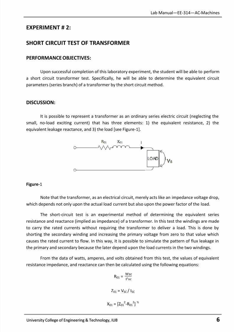
DISCUSSION:
It is possible to represent a transformer as an ordinary series electric circuit (neglecting thesmall, no-load exciting current) that has three elements: 1) the equivalent resistance, 2) the
equivalent leakage reactance, and 3) the load [see Figure-1].
Figure-1
Note that the transformer, as an electrical circuit, merely acts like an impedance voltage drop,
which depends not only upon the actual load current but also upon the power factor of the load.
The short-circuit test is an experimental method of determining the equivalent series
resistance and reactance (implied as impedance) of a transformer. In this test the windings are made
to carry the rated currents without requiring the transformer to deliver a load. This is done by
shorting the secondary winding and increasing the primary voltage from zero to that value which
causes the rated current to flow. In this way, it is possible to simulate the pattern of flux leakage in
the primary and secondary because the later depend upon the load currents in the two windings.
From the data of watts, amperes, and volts obtained from this test, the values of equivalent
resistance impedance, and reactance can then be calculated using the following equations:
R01 =ୱୡ
²ୱୡ
Z01 = VSC / ISC
X01 = [Z012-R01
2]
½
7/27/2019 AC Electric Machines Lab manul
http://slidepdf.com/reader/full/ac-electric-machines-lab-manul 9/98
Lab Manual—EE-314—AC-Machines
University College of Engineering & Technology, IUB ϋ
EQUIPMENT:
• Single Phase Transformer
• AC Power Meter
• Variable Power Supply
• Connecting Wires
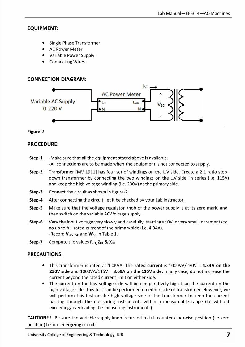
CONNECTION DIAGRAM:
Figure-2
PROCEDURE:
Step-1 -Make sure that all the equipment stated above is available.
-All connections are to be made when the equipment is not connected to supply.
Step-2 Transformer [MV-1911] has four set of windings on the L.V side. Create a 2:1 ratio step-
down transformer by connecting the two windings on the L.V side, in series (i.e. 115V)
and keep the high voltage winding (i.e. 230V) as the primary side.
Step-3 Connect the circuit as shown in figure-2.
Step-4 After connecting the circuit, let it be checked by your Lab Instructor.
Step-5 Make sure that the voltage regulator knob of the power supply is at its zero mark, and
then switch on the variable AC-Voltage supply.
Step-6 Vary the input voltage very slowly and carefully, starting at 0V in very small increments to
go up to full rated current of the primary side (i.e. 4.34A).
-Record VSC, ISC and WSC in Table 1.
Step-7 Compute the values R01, Z01 & X01
PRECAUTIONS:
• This transformer is rated at 1.0KVA. The rated current is 1000VA/230V = 4.34A on the
230V side and 1000VA/115V = 8.69A on the 115V side. In any case, do not increase the
current beyond the rated current limit on either side.
• The current on the low voltage side will be comparatively high than the current on the
high voltage side. This test can be performed on either side of transformer. However, we
will perform this test on the high voltage side of the transformer to keep the current
passing through the measuring instruments within a measureable range (i.e without
exceeding/overloading the measuring instruments).
CAUTION!!! Be sure the variable supply knob is turned to full counter-clockwise position (i.e zero
position) before energizing circuit.

7/27/2019 AC Electric Machines Lab manul
http://slidepdf.com/reader/full/ac-electric-machines-lab-manul 10/98
Lab Manual—EE-314—AC-Machines
University College of Engineering & Technology, IUB ό
TEST RESULTS:
VSC ISC WSC R01 Z01 X01
Table-1
REVIEW QUESTIONS:
1. What is the equivalent circuit found in the short-circuit test?
2. Write the formula for calculating the value of equivalent series resistance, impedance, and
reactance of a transformer. ____________________________________________________________________________
____________________________________________________________________________
____________________________________________________________________________
3. Refer these calculations to the secondary.
____________________________________________________________________________
____________________________________________________________________________
____________________________________________________________________________
FINAL CHECKLIST:
1. Clean your equipment/materials and work benches before you leave.
2. Return all equipment and materials to their proper storage area.
3. Submit your answers to the questions, together with your data, calculations, and results
before the next laboratory session.
_________________
Signature:
Lab Instructor
7/27/2019 AC Electric Machines Lab manul
http://slidepdf.com/reader/full/ac-electric-machines-lab-manul 11/98
Lab Manual—EE-314—AC-Machines
University College of Engineering & Technology, IUB ύ
EXPERIMENT # 3:
TRANSFORMER EFFICIENCY
PERFORMANCE OBJECTIVES:
Upon successful completion of this experiment the student will be able to:
1. Investigate the methods of determining percent of Efficiency of a Transformer, at unity
power factor loads.
2. The effect of load on Efficiency of Transformer.
DISCUSSION:
Referring to the information obtained from the short circuit test and open circuit transformer
tests, it is easily seen that losses are confined to two basic categories:
1. Core losses- (Eddy currents and hysteresis losses), which are proportional to applied voltage
and are measured in terms of true power. These losses are essentially constant for all values
of transformer loading provided that the applied voltages remain same. This is true because
flux is essentially constant for these values.
2. Copper losses- Vary as the square of the load current. This loss is not constant but must be
computed for all values of load current.
The percent efficiency can be computed from the following formula for each load value from
no-load to full load:
Efficiency = ˟ 100 =ሺ ା ሻ
˟ 100
Since the losses can be reduced to a very small percentage by good design, it is not uncommon to
have efficiencies as high as 98 – 99 % in large transformers. Because the relationship to power-in and
power-out are so close, it may prove difficult to achieve good results from the measuring procedure.
EQUIPMENT:
• Single Phase Transformer
• 2 - AC Power Meter
• Variable Power Supply
• Connecting Leads.
7/27/2019 AC Electric Machines Lab manul
http://slidepdf.com/reader/full/ac-electric-machines-lab-manul 12/98
Lab Manual—EE-314—AC-Machines
University College of Engineering & Technology, IUB υτ
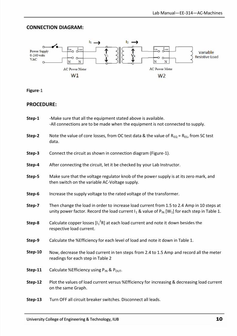
CONNECTION DIAGRAM:
Figure-1
PROCEDURE:
Step-1 -Make sure that all the equipment stated above is available.-All connections are to be made when the equipment is not connected to supply.
Step-2 Note the value of core losses, from OC test data & the value of REQ = R01, from SC test
data.
Step-3 Connect the circuit as shown in connection diagram (Figure-1).
Step-4 After connecting the circuit, let it be checked by your Lab Instructor.
Step-5 Make sure that the voltage regulator knob of the power supply is at its zero mark, andthen switch on the variable AC-Voltage supply.
Step-6 Increase the supply voltage to the rated voltage of the transformer.
Step-7 Then change the load in order to increase load current from 1.5 to 2.4 Amp in 10 steps at
unity power factor. Record the load current I1 & value of PIN [W1] for each step in Table 1.
Step-8 Calculate copper losses [I12R] at each load current and note it down besides the
respective load current.
Step-9 Calculate the %Efficiency for each level of load and note it down in Table 1.
Step-10 Now, decrease the load current in ten steps from 2.4 to 1.5 Amp and record all the meter
readings for each step in Table 2
Step-11 Calculate %Efficiency using PIN & POUT.
Step-12 Plot the values of load current versus %Efficiency for increasing & decreasing load current
on the same Graph.
Step-13 Turn OFF all circuit breaker switches. Disconnect all leads.

7/27/2019 AC Electric Machines Lab manul
http://slidepdf.com/reader/full/ac-electric-machines-lab-manul 13/98
Lab Manual—EE-314—AC-Machines
University College of Engineering & Technology, IUB υυ
TEST RESULTS:
R01 = REQ = ________ (from SC test data)
Core Losses = ________ (from OC test data)
Load
Current [I1]
Copper
Losses[I12R1]
PIN [W1]
% Efficiency
Table-1
PR
I
Volts
Amperes
Watts
S
E
C
Volts
Amperes
Watts
% EFF
Measured
Table-2
7/27/2019 AC Electric Machines Lab manul
http://slidepdf.com/reader/full/ac-electric-machines-lab-manul 14/98
Lab Manual—EE-314—AC-Machines
University College of Engineering & Technology, IUB υφ
GRAPH:
7/27/2019 AC Electric Machines Lab manul
http://slidepdf.com/reader/full/ac-electric-machines-lab-manul 15/98
Lab Manual—EE-314—AC-Machines
University College of Engineering & Technology, IUB υχ
REVIEW QUESTIONS:
1. How the change in load current does effects the efficiency of transformer?
__________________________________________________________________________________
__________________________________________________________________________________
2. What is the condition for the maximum efficiency of the transformer?
__________________________________________________________________________________
__________________________________________________________________________________
1. During the Locked Rotor Test, all of the input power was lost in the motor’s equivalent
resistance. The equation is:
W = 3 x (ILR)2
x REQ
Solving for REQ the equation becomes REQ = W/(3 x I2). From the data you recorded in Table-2
compute the total power in (TOT. W) and REQ. Record these values in TABLE-2.
2. During the No-Load-Test, the input power was lost in both the equivalent resistance and in
the rotational losses (PRL) To find the value of PRL first compute the total power in. Then
compute the total copper losses:
PCL = 3 x (INL)2
x REQ
Using the value of REQ = Total. W. PCL. Record this value of PRL Table-1 and for every load
listed in Table-3. (PRL assumed constant).
3. For each of the motor current values in TABLE-3, add the wattmeter readings to provide the
total power in. Record these values in TABLE-3.
4. For each of the motor current values in TABLE 16-3 compute the total copper loss from the
equation PCL = 3 x x REQ using the value of REQ from TABLE-2. Record the copper loss values
in TABLE-3. Add each of these values to the value computed in No. 2 to produce the
total loss value for each of the loads. Record these values in TABLE 16-3.
5. Compute efficiency, the ratio of output power to input power. For output power subtract
the losses from the output power. The equation is:
% Efficiency = Total Watts in - PL x 100
Total Watts in
List these efficiencies in TABLE-3.
6. As load increases, rotational losses:
a. Increase.b. Decrease.
c. Remain the same.
7/27/2019 AC Electric Machines Lab manul
http://slidepdf.com/reader/full/ac-electric-machines-lab-manul 16/98
Lab Manual—EE-314—AC-Machines
University College of Engineering & Technology, IUB υψ
7. As load increases, copper losses:
a. Increase.
b. Decrease.
c. Remain the same.
8. As load increases, the total losses become:
a. A larger share of the total power in.
b. A smaller share of the total power in.
c. The same share of the total power in.
9. As load increase, the motor:
a. Operates more efficiently.
b. Operates less efficiently.c. Operates with the same efficiency.
10. Power Out equals:
a. The power in.
b. The total of copper and rotational losses.
c. The power in minus the total losses.
FINAL CHECKLIST:
1. Clean your equipment/materials and work benches before you leave.
2. Return all equipment and materials to their proper storage area.
3. Submit your answers to the questions, together with your data, calculations, and results
before the next laboratory session.
____________Signature:
Lab Instructor
7/27/2019 AC Electric Machines Lab manul
http://slidepdf.com/reader/full/ac-electric-machines-lab-manul 17/98
7/27/2019 AC Electric Machines Lab manul
http://slidepdf.com/reader/full/ac-electric-machines-lab-manul 18/98
Lab Manual—EE-314—AC-Machines
University College of Engineering & Technology, IUB υϊ
The rotors of induction motors (squirrel-cage or wound rotor) can never run at synchronous
speed. There must be relative motion between the field and the rotor so that induction may take
place. The difference between synchronous speed and rotor speed is called slip speed, or simply slip.
The percent slip can be computed from the following equation:
%Slip = Slip Speed____
Synchronous Speed
EQUIPMENT:
• Three-Phase Induction Motor
• Torque-Speed measuring unit
• Variable Power Supply
• Connecting Leads.
CONNECTION DIAGRAM:
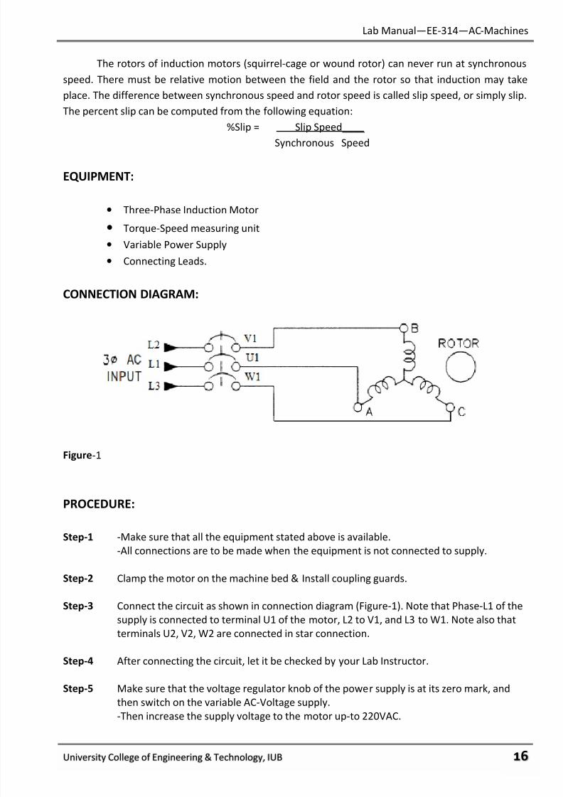
Figure-1
PROCEDURE:
Step-1 -Make sure that all the equipment stated above is available.
-All connections are to be made when the equipment is not connected to supply.
Step-2 Clamp the motor on the machine bed & Install coupling guards.
Step-3 Connect the circuit as shown in connection diagram (Figure-1). Note that Phase-L1 of the
supply is connected to terminal U1 of the motor, L2 to V1, and L3 to W1. Note also that
terminals U2, V2, W2 are connected in star connection.
Step-4 After connecting the circuit, let it be checked by your Lab Instructor.
Step-5 Make sure that the voltage regulator knob of the power supply is at its zero mark, and
then switch on the variable AC-Voltage supply.
-Then increase the supply voltage to the motor up-to 220VAC.
7/27/2019 AC Electric Machines Lab manul
http://slidepdf.com/reader/full/ac-electric-machines-lab-manul 19/98
Lab Manual—EE-314—AC-Machines
University College of Engineering & Technology, IUB υϋ
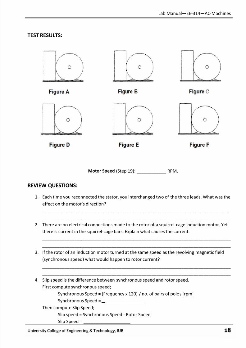
Step-6 Note the direction of rotation as that viewed from the right-hand end, indicate the
direction on Figure. A of TEST RESULTS.
Step-7 Turn OFF the motor.
Step-8 Reconnect the stator as follows: Leaving L3 connected to W1, interchange the other two
leads so that L1 is connected to V1; L2 to U1.
Step-9 Repeat Step 5 & 6 for Figure. B of TEST RESULTS, then turn OFF the motor.
Step-10 Reconnect the stator as follows: Leaving L1 connected to V1, interchange the other two
leads so that L2 is connected to W1; L3 to U1.
Step-11 Repeat Step 5 & 6 for Figure. C of TEST RESULTS, then turn OFF the motor.
Step-12 Reconnect the stator as follows: Leaving L3 connected to U1, interchange the other two
leads so that L1 is connected toW1; L2 to V1.
Step-13 Repeat Step 5 & 6 for Figure. D of TEST RESULTS, then turn OFF the motor.
Step-14 Reconnect the stator as follows: Leaving L1 connected to W1, interchange the other two
leads so that L2 is connected to U1; L3 to V1.
Step-15 Repeat Step 5 & 6 for Figure. E of TEST RESULTS, then turn OFF the motor.
Step-16 Reconnect the stator as follows: Leaving L3 connected to V1, interchange the other two
leads so that L1 is connected to U1; L2 to W1.
Step-17 Repeat Step 5 & 6 for Figure. F of TEST RESULTS, then turn OFF the motor.
Step-18 Leaving L1 connected to U1, interchange the other two leads so that the connection is
the same as shown in Figure 1.
Step-19 Turn ON the motor. Measure the speed of the unloaded motor. Record it in Test Results.
Step-20 Turn OFF all circuit breaker switches. Disconnect all leads.
7/27/2019 AC Electric Machines Lab manul
http://slidepdf.com/reader/full/ac-electric-machines-lab-manul 20/98
Lab Manual—EE-314—AC-Machines
University College of Engineering & Technology, IUB υό
TEST RESULTS:
Motor Speed (Step 19): ____________ RPM.
REVIEW QUESTIONS:
1. Each time you reconnected the stator, you interchanged two of the three leads. What was the
effect on the motor’s direction?
____________________________________________________________________________
____________________________________________________________________________
2. There are no electrical connections made to the rotor of a squirrel-cage induction motor. Yet
there is current in the squirrel-cage bars. Explain what causes the current.
____________________________________________________________________________
____________________________________________________________________________
3. If the rotor of an induction motor turned at the same speed as the revolving magnetic field
(synchronous speed) what would happen to rotor current?
____________________________________________________________________________
____________________________________________________________________________
4. Slip speed is the difference between synchronous speed and rotor speed.
First compute synchronous speed;
Synchronous Speed = (Frequency x 120) / no. of pairs of poles [rpm]
Synchronous Speed = ________________
Then compute Slip Speed;
Slip speed = Synchronous Speed - Rotor Speed
Slip Speed = ___________________
7/27/2019 AC Electric Machines Lab manul
http://slidepdf.com/reader/full/ac-electric-machines-lab-manul 21/98
Lab Manual—EE-314—AC-Machines
University College of Engineering & Technology, IUB υύ
5. Percent slip is the ratio of slip speed to synchronous speed [%Slip = (Slip Speed/Synchronous
Speed) x 100]. What is the percent slip of the test motor running unloaded?
____________________________________________________________________________
____________________________________________________________________________
6. The main (stator) field of a three-phase motor revolves because:
a) DC is applied to the rotor coils.
b) DC is applied to the stator coils.
c) Three out-of-phase voltages are applied to the stator coils.
7. If the coil that is connected to Phase B line is to the left of the coil connected to Phase A line,
the magnetic field of the stator will:
a) Revolve to the right.
b) Revolve to the left.
c) Go straight ahead.
8. To reverse the direction of a three-phase motor, you must:
a) Reverse the motor connections.
b) Change all three stator connections.
c) Interchange any two stator connections.
9. 3-phase Induction Motors must:
a) Run faster than synchronous speed.
b) Run slower than synchronous speed.
c) Run at synchronous speed.
10. Synchronous speed is determined by:
a) Frequency and number of poles.
b) Torque and speed of driven load.
c) Field strength and armature current.
FINAL CHECKLIST:
1. Clean your equipment/materials and work benches before you leave.
2. Return all equipment and materials to their proper storage area.
3. Submit your answers to the questions, together with your data, calculations, and results
before the next laboratory session.
____________
Signature:
Lab Instructor
7/27/2019 AC Electric Machines Lab manul
http://slidepdf.com/reader/full/ac-electric-machines-lab-manul 22/98
7/27/2019 AC Electric Machines Lab manul
http://slidepdf.com/reader/full/ac-electric-machines-lab-manul 23/98
Lab Manual—EE-314—AC-Machines
University College of Engineering & Technology, IUB φυ
Knowing this allows us to lock the rotor and measure starting torque at a reduced voltage; then
compute what it would be at full voltage. If full voltage were applied, the high starting current would
trip the circuit breakers before we could get a reading.
EQUIPMENT:
• Three Phase Squirrel-Cage Induction Motor
• Torque-Speed measuring unit
• AC power meters
• Variable Power Supply
• Connecting Leads.
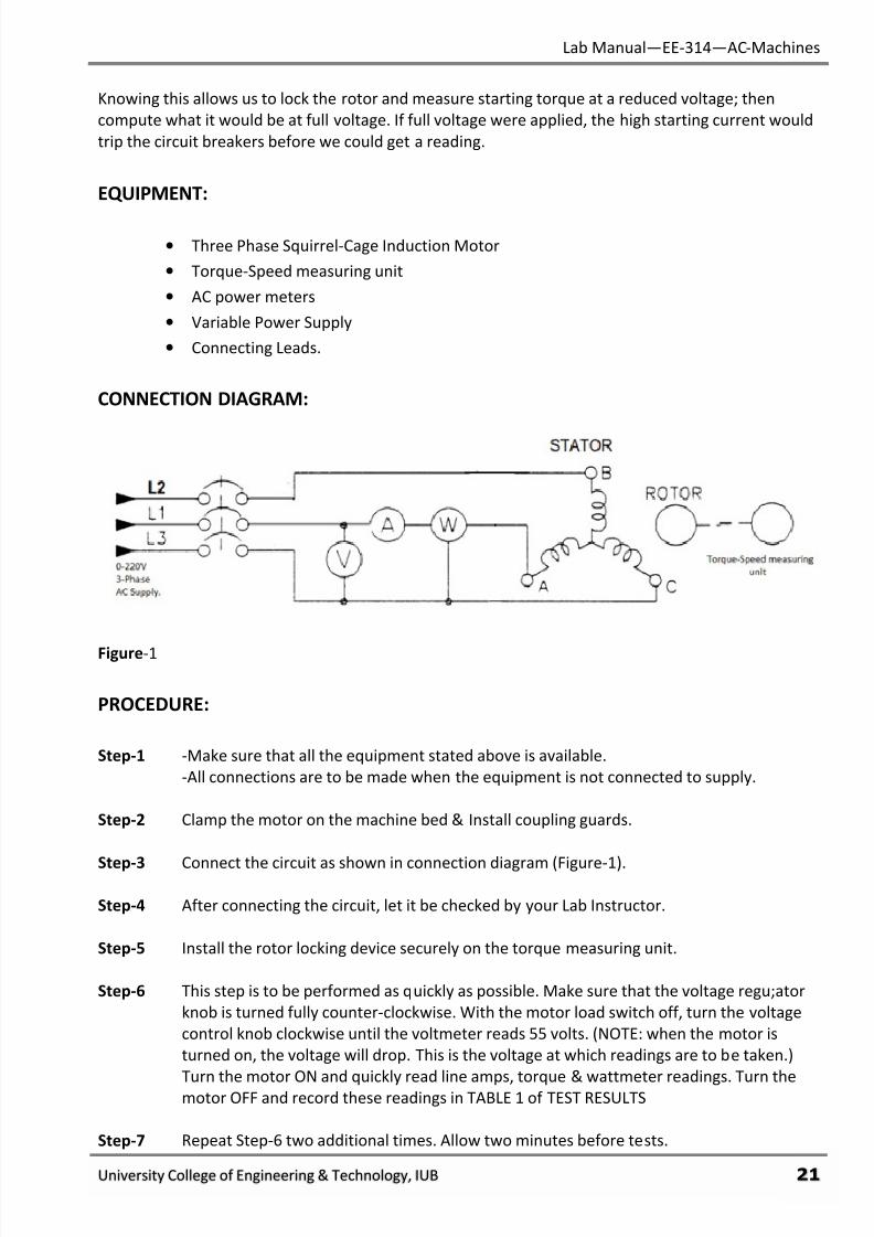
CONNECTION DIAGRAM:
Figure-1
PROCEDURE:
Step-1 -Make sure that all the equipment stated above is available.
-All connections are to be made when the equipment is not connected to supply.
Step-2 Clamp the motor on the machine bed & Install coupling guards.
Step-3 Connect the circuit as shown in connection diagram (Figure-1).
Step-4 After connecting the circuit, let it be checked by your Lab Instructor.
Step-5 Install the rotor locking device securely on the torque measuring unit.
Step-6 This step is to be performed as quickly as possible. Make sure that the voltage regu;ator
knob is turned fully counter-clockwise. With the motor load switch off, turn the voltage
control knob clockwise until the voltmeter reads 55 volts. (NOTE: when the motor is
turned on, the voltage will drop. This is the voltage at which readings are to be taken.)
Turn the motor ON and quickly read line amps, torque & wattmeter readings. Turn themotor OFF and record these readings in TABLE 1 of TEST RESULTS
Step-7 Repeat Step-6 two additional times. Allow two minutes before tests.
7/27/2019 AC Electric Machines Lab manul
http://slidepdf.com/reader/full/ac-electric-machines-lab-manul 24/98
Lab Manual—EE-314—AC-Machines
University College of Engineering & Technology, IUB φφ
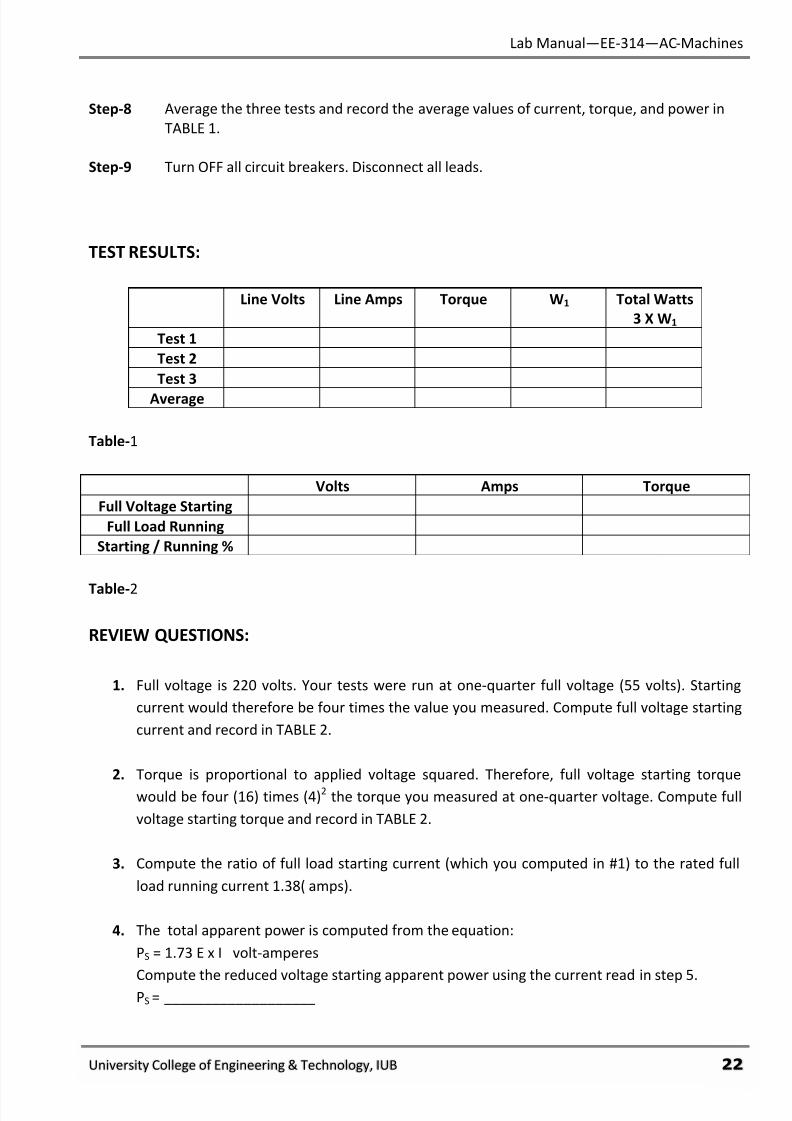
Step-8 Average the three tests and record the average values of current, torque, and power in
TABLE 1.
Step-9 Turn OFF all circuit breakers. Disconnect all leads.
TEST RESULTS:
Line Volts Line Amps Torque W1 Total Watts
3 X W1
Test 1
Test 2
Test 3
Average
Table-1
Volts Amps Torque
Full Voltage Starting
Full Load Running
Starting / Running %
Table-2
REVIEW QUESTIONS:
1. Full voltage is 220 volts. Your tests were run at one-quarter full voltage (55 volts). Starting
current would therefore be four times the value you measured. Compute full voltage starting
current and record in TABLE 2.
2. Torque is proportional to applied voltage squared. Therefore, full voltage starting torque
would be four (16) times (4)2
the torque you measured at one-quarter voltage. Compute full
voltage starting torque and record in TABLE 2.
3. Compute the ratio of full load starting current (which you computed in #1) to the rated full
load running current 1.38( amps).
4. The total apparent power is computed from the equation:
PS = 1.73 E x I volt-amperes
Compute the reduced voltage starting apparent power using the current read in step 5.PS = ___________________
7/27/2019 AC Electric Machines Lab manul
http://slidepdf.com/reader/full/ac-electric-machines-lab-manul 25/98
Lab Manual—EE-314—AC-Machines
University College of Engineering & Technology, IUB φχ
5. The True power (P) at reduced voltage is the sum of the two-wattmeter readings. The power
factor is the ratio of true power to apparent power-P.F. = P/PS. Compute the power factor
(cosɵ).
P.F = _________________
6. Starting current is:
a. Greater than full load current.
b. Less than full load current
c. The same as full load current.
7. Full load running torque is:
a. Greater than starting torque.
b. Less than starting torque.
c. The same as starting torque.
8. Each amp of starting current provides:
a. The same torque as each amp of running current.
b. More torque than each amp of runnings current.
c. Less torque than each amp of running current.
9. You would get more in-oz of starting torque from each amp of starting current if:
a. There was more inductive reactance in the rotor.
b. There was more resistance in the rotor.
c. The rotor bars did not form a complete circuit.
10. At the instant of start, an induction motor has:
a. A leading phase angle
b.
A good power factor, small lagging phase angle.c. A poor power factor, large lagging phase angle.
FINAL CHECKLIST:
1. Clean your equipment/materials and work benches before you leave.
2. Return all equipment and materials to their proper storage area.
3. Submit your answers to the questions, together with your data, calculations, and results
before the next laboratory session.
____________
Signature:
Lab Instructor
7/27/2019 AC Electric Machines Lab manul
http://slidepdf.com/reader/full/ac-electric-machines-lab-manul 26/98
Lab Manual—EE-314—AC-Machines
University College of Engineering & Technology, IUB φψ
EXPERIMENT # 6:
RUNNINIG CHARACTERISTICS OF SQUIRREL CAGE INDUCTION MOTOR
PERFORMANCE OBJECTIVES:
Upon successful completion of this experiment the student will be able to:
1. Explain and predict the changes in speed and current that will occur as a squirrel- cage
induction motor is loaded.
2. Perform load tests on three-phase motors.
DISCUSSION:
The speed at which the stator’s field revolves is the synchronous speed. As this field is cut by
the bars of the squirrel-cage rotor winding, current is induced into the bars. The rotor’s magnetic
field (caused by this current) interacts with the stator’s field to produce torque on the rotor.
The torque is directly proportional to rotor current, and the cosine of the phase angle
between the rotor and stator fields (cos ɵ). Another way of expressing this relationship is that
torque is directly proportional to the in-phase component of rotor current, IR cos ɵ.
At the instant of start, IR is high but the in-phase component is low because of the poor
power factor (cos ɵ). As the rotor picks up speed, both the induced rotor voltage and the inductivereactance decrease. Basically IR is going down while cos ɵ is going up.
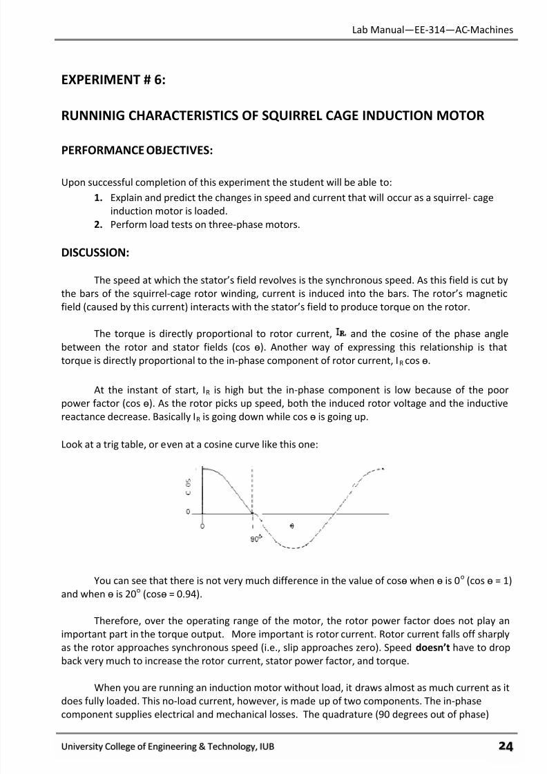
Look at a trig table, or even at a cosine curve like this one:
You can see that there is not very much difference in the value of cosɵ when ɵ is 0o
(cos ɵ = 1)
and when ɵ is 20o
(cosɵ = 0.94).
Therefore, over the operating range of the motor, the rotor power factor does not play an
important part in the torque output. More important is rotor current. Rotor current falls off sharply
as the rotor approaches synchronous speed (i.e., slip approaches zero). Speed doesn’t have to drop
back very much to increase the rotor current, stator power factor, and torque.
When you are running an induction motor without load, it draws almost as much current as it
does fully loaded. This no-load current, however, is made up of two components. The in-phase
component supplies electrical and mechanical losses. The quadrature (90 degrees out of phase)
7/27/2019 AC Electric Machines Lab manul
http://slidepdf.com/reader/full/ac-electric-machines-lab-manul 27/98
Lab Manual—EE-314—AC-Machines
University College of Engineering & Technology, IUB φω
component is the magnetizing current. It is quite large in comparison with the in- phase part. As the
motor is loaded, it is like putting a resistive load on the secondary of a transformer. The in-phase
component gets larger. The stator’s power factor improves accordingly. The increased rotor current
does not necessarily add to the total current being drawn by the motor. It simply uses more of that
current for useful work.
In this experiment we will be using the two-wattmeter method of measuring power input. At
no-load, power factor is less than 0.5. That means that one wattmeter must be connected with its
voltage coils reversed and its reading subtracted from the other one. As the motor is loaded, the
power factor improves. When it reaches 0.5, the potential coil connections must be connected
normally, its reading added to the other one.
EQUIPMENT:
• Induction Motor (Squirrel-Cage)
• DC Machine (operating as DC-Generator.)
• Torque Speed Measuring Unit.
• Variable Power Supply.
• AC-Power Meters.
• Digital Multi-Meters
• Resistive load.
• Connecting Leads.
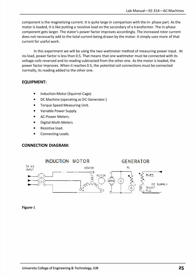
CONNECTION DIAGRAM:
Figure-1
7/27/2019 AC Electric Machines Lab manul
http://slidepdf.com/reader/full/ac-electric-machines-lab-manul 28/98
Lab Manual—EE-314—AC-Machines
University College of Engineering & Technology, IUB φϊ
PROCEDURE:
Step-1 -Make sure that all the equipment stated above is available.
-All connections are to be made when the equipment is not connected to supply.
Step-2 Place the DC-Machine (operating as DC-Generator) on the machine bed on the left side of
torque speed measuring unit & Induction Motor on the right side. Couple and clamp the
machines securely & Install guards.
Step-3 Connect the circuit as shown in connection diagram (Figure-1). Note that the DC-Machine
is connected as a separately-excited shunt generator. Make sure that the switch for the
load connected to the generator is in OFF position.
Step-4 After connecting the circuit, let it be checked by your Lab Instructor.
Step-5 Make sure that the voltage regulator knob of the power supply is at its zero mark, andthen switch on the variable AC-Voltage supply.
Step-6 Increase the supply voltage to motor’s stator winding, up-to the rated voltage.
Step-7 Turn on the DC-Voltage supply and adjust the excitation of DC-Machine until the
generator terminal voltages reach 220 V. Note that the DC-Machine is connected as
shunt excited generator.
Step-8 Record the values of line & load amps, W, torque, and speed in TABLE-1 of TEST RESULTS,
under “NO LOAD”.
Step-9 Turn ON the resistive load and adjust its value until load current reaches 0.25A.
Step-10 Readjust the generator’s field rheostat or the excitation supply, as required, to maintain a
terminal voltage of 220 volts. Then repeat Step 8.
Step-11 Now vary the resistive load and adjust its value until load current reaches 0.5A.
Step-12 Repeat step-10.
Step-13 Now vary the resistive load and adjust its value until load current reaches 1.0A.
Step-14 Repeat step-10
Step-15 Turn OFF all circuit breaker switches. Disconnect all leads.
7/27/2019 AC Electric Machines Lab manul
http://slidepdf.com/reader/full/ac-electric-machines-lab-manul 29/98
Lab Manual—EE-314—AC-Machines
University College of Engineering & Technology, IUB φϋ
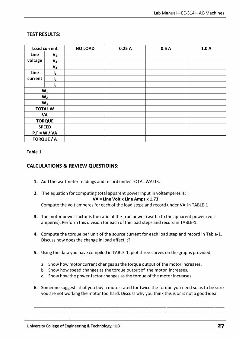
TEST RESULTS:
Load current NO LOAD 0.25 A 0.5 A 1.0 A
Line
voltage
V1
V2 V3
Line
current
I1
I2
I3
W1
W2
W3
TOTAL W
VA
TORQUE
SPEED
P.F = W / VA
TORQUE / A
Table-1
CALCULATIONS & REVIEW QUESTIOINS:
1. Add the wattmeter readings and record under TOTAL WATtS.
2. The equation for computing total apparent power input in voltamperes is:
VA = Line Volt x Line Amps x 1.73
Compute the volt amperes for each of the load steps and record under VA in TABLE-1
3. The motor power factor is the ratio of the true power (watts) to the apparent power (volt-
amperes). Perform this division for each of the load steps and record in TABLE-1.
4. Compute the torque per unit of the source current for each load step and record in Table-1.
Discuss how does the change in load affect it?
5. Using the data you have compiled in TABLE-1, plot three curves on the graphs provided.
a. Show how motor current changes as the torque output of the motor increases.
b. Show how speed changes as the torque output of the motor increases.
c. Show how the power factor changes as the torque of the motor increases.
6. Someone suggests that you buy a motor rated for twice the torque you need so as to be sure
you are not working the motor too hard. Discuss why you think this is or is not a good idea.
_______________________________________________________________________________
_______________________________________________________________________________
_______________________________________________________________________________
7/27/2019 AC Electric Machines Lab manul
http://slidepdf.com/reader/full/ac-electric-machines-lab-manul 30/98
Lab Manual—EE-314—AC-Machines
University College of Engineering & Technology, IUB φό
7. Over the operating range of an induction motor (no load to full load):
a. There is a large variation in speed.
b. There is absolutely no variation in speed.
c. There is a small variation in speed.
8. From no load to full load, there is:
a. Considerable change in power factor.
b. A small change in power factor.
c. Absolutely no change in power factor.
9. At no load, poor motor power factor is due to:
a. The high frequency of induced rotor voltage.
b. The rotor power factor.
c. The quadrature stator magnetizing current.
10. The mechanical power of the rotor is supplied by:
a. Active Power input to the stator.
b. Reactive Power input to the stator.
c. Apparent Power input to the stator.
11. The frequency and value of induced rotor voltage depends on:
a. The rotor speed only.
b. The difference between rotor speed and the speed of the revolving stator field.
c. Synchronous speed only.

7/27/2019 AC Electric Machines Lab manul
http://slidepdf.com/reader/full/ac-electric-machines-lab-manul 31/98
Lab Manual—EE-314—AC-Machines
University College of Engineering & Technology, IUB φύ
GRAPH:
No. 1
No. 2
7/27/2019 AC Electric Machines Lab manul
http://slidepdf.com/reader/full/ac-electric-machines-lab-manul 32/98
Lab Manual—EE-314—AC-Machines
University College of Engineering & Technology, IUB χτ
No. 3
FINAL CHECKLIST:
1. Clean your equipment/materials and work benches before you leave.
2. Return all equipment and materials to their proper storage area.
3. Submit your answers to the questions, together with your data, calculations, and results
before the next laboratory session.
____________
Signature:
Lab Instructor
7/27/2019 AC Electric Machines Lab manul
http://slidepdf.com/reader/full/ac-electric-machines-lab-manul 33/98
Lab Manual—EE-314—AC-Machines
University College of Engineering & Technology, IUB χυ
EXPERIMENT # 7:
STARTING CHARACTERISTICS OF WOUND-ROTOR INDUCTION MOTORS
PERFORMANCE OBJECTIVES:
After successful completion of this experiment the student will be able to:
• Explain the addition of resistance to the rotor circuit of wound-rotor motors.
• Perform locked-rotor tests on wound-rotor motors.
• Determine the effect that rotor circuit resistance has on the starting torque of a wound-rotor
induction motor.
DISCUSSION:
The reason you don’t get more starting torque from a squirrel-cage induction motor is that it
has such a poor power factor. Its inductive reactance is high in comparison to its resistance. Of
course, squirrel-cage rotors could be made with greater resistance, but that would hurt the running
characteristics.
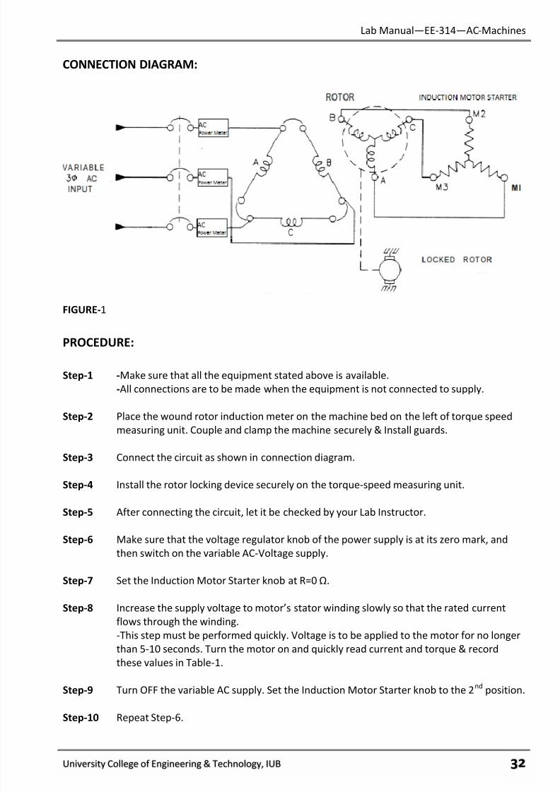
The rotor of a wound-rotor motor has coils. It is wound to have the same number of poles as
the stator. The rotor coils are Y-connected internally with the other end of each coil terminating
outside of the motor housing. An external variable resistance box is connected to the rotor terminals.This box is designed to add and remove resistance from the three phases simultaneously. Generally
speaking, the more resistance you have in the rotor circuit at start, the more starting torque you will
get for each ampere of starting current. The disadvantage is that power is being dissipated (lost)
outside of the motor. While it is improving starting current phase angle, the resistance also has the
effect of reducing rotor current. If you put in too much resistance, the lower current will wipe out the
advantage you had from improved power factor.
EQUIPMENT:
• Three Phase Wound-Rotor Induction Motor.
• Torque Speed Measuring Unit.
• Variable AC Supply.
• AC-Power Meters.
• Induction Motor Starter.
• Connecting Leads.
7/27/2019 AC Electric Machines Lab manul
http://slidepdf.com/reader/full/ac-electric-machines-lab-manul 34/98
Lab Manual—EE-314—AC-Machines
University College of Engineering & Technology, IUB χφ
CONNECTION DIAGRAM:
FIGURE-1
PROCEDURE:
Step-1 -Make sure that all the equipment stated above is available.
-All connections are to be made when the equipment is not connected to supply.
Step-2 Place the wound rotor induction meter on the machine bed on the left of torque speedmeasuring unit. Couple and clamp the machine securely & Install guards.
Step-3 Connect the circuit as shown in connection diagram.
Step-4 Install the rotor locking device securely on the torque-speed measuring unit.
Step-5 After connecting the circuit, let it be checked by your Lab Instructor.
Step-6 Make sure that the voltage regulator knob of the power supply is at its zero mark, and
then switch on the variable AC-Voltage supply.
Step-7 Set the Induction Motor Starter knob at R=0 Ω.
Step-8 Increase the supply voltage to motor’s stator winding slowly so that the rated current
flows through the winding.
-This step must be performed quickly. Voltage is to be applied to the motor for no longer
than 5-10 seconds. Turn the motor on and quickly read current and torque & record
these values in Table-1.
Step-9 Turn OFF the variable AC supply. Set the Induction Motor Starter knob to the 2
nd
position.
Step-10 Repeat Step-6.
7/27/2019 AC Electric Machines Lab manul
http://slidepdf.com/reader/full/ac-electric-machines-lab-manul 35/98
Lab Manual—EE-314—AC-Machines
University College of Engineering & Technology, IUB χχ
Step-11 Turn OFF the variable AC supply. Set the Induction Motor Starter knob to the 3rd
position.
Step-12 Repeat Step-6.
Step-13 Turn OFF the variable AC supply. Set the Induction Motor Starter knob to the 4th
position.
Step-14 Repeat Step-6.
Step-15 Turn OFF all circuit breakers. Disconnect all leads.
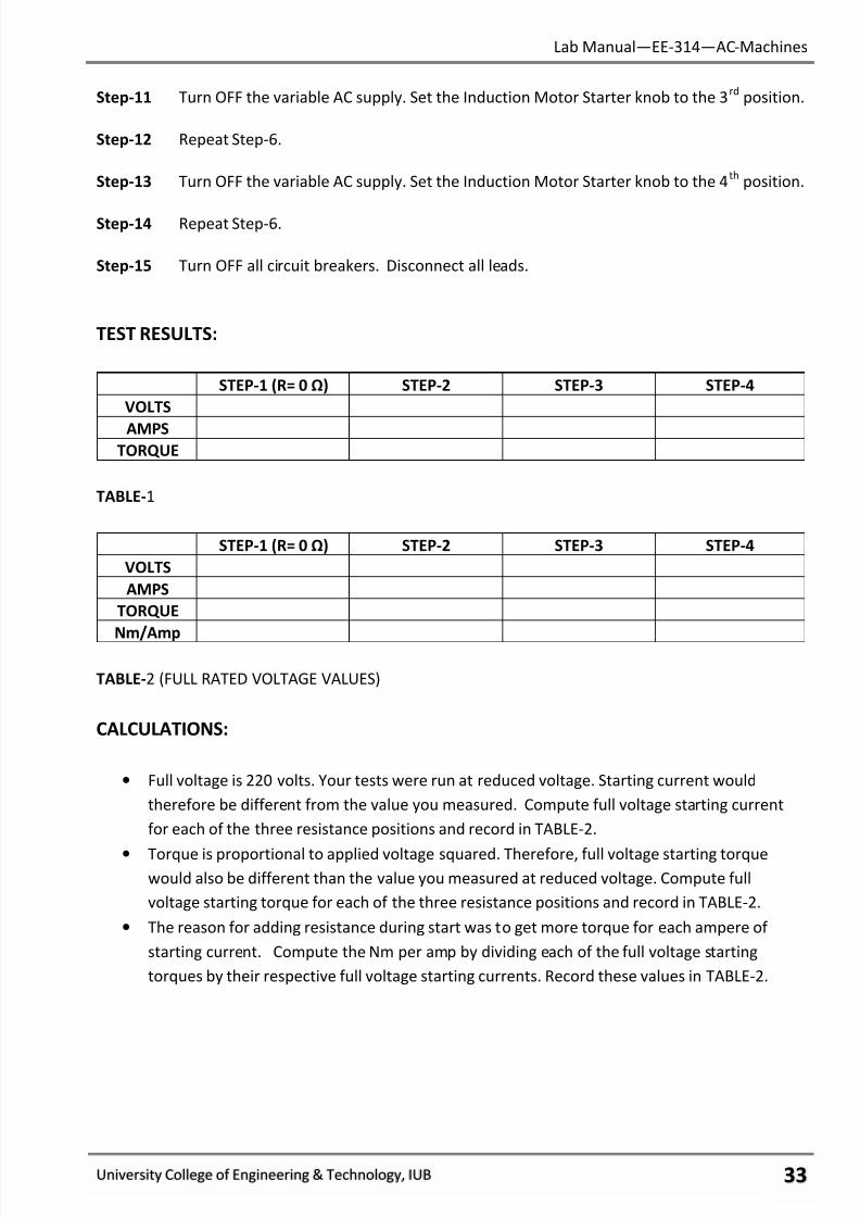
TEST RESULTS:
STEP-1 (R= 0 Ω) STEP-2 STEP-3 STEP-4
VOLTS
AMPSTORQUE
TABLE-1
STEP-1 (R= 0 Ω) STEP-2 STEP-3 STEP-4
VOLTS
AMPS
TORQUE
Nm/Amp
TABLE-2 (FULL RATED VOLTAGE VALUES)
CALCULATIONS:
• Full voltage is 220 volts. Your tests were run at reduced voltage. Starting current would
therefore be different from the value you measured. Compute full voltage starting current
for each of the three resistance positions and record in TABLE-2.
• Torque is proportional to applied voltage squared. Therefore, full voltage starting torquewould also be different than the value you measured at reduced voltage. Compute full
voltage starting torque for each of the three resistance positions and record in TABLE-2.
• The reason for adding resistance during start was to get more torque for each ampere of
starting current. Compute the Nm per amp by dividing each of the full voltage starting
torques by their respective full voltage starting currents. Record these values in TABLE-2.
7/27/2019 AC Electric Machines Lab manul
http://slidepdf.com/reader/full/ac-electric-machines-lab-manul 36/98
Lab Manual—EE-314—AC-Machines
University College of Engineering & Technology, IUB χψ
REVIEW QUESTIONS:
1. Addition of rotor resistance tends to reduce starting torque. Why, then, is it used?
____________________________________________________________________________
____________________________________________________________________________
________________________________________________________________________
2. With maximum rotor resistance connected, the starting current is:
a. Greater than without the resistance.
b. Less than without the resistance.
c. The same as without the resistance.
3. As rotor resistance was increased, the starting torque;
a. Decreased.
b. Increased.
c. Remained the same.
4. up to a point, adding resistance to the rotor resistance to the rotor circuit provides:
a. More torque per ampere of starting current.
b. Less torque per ampere of starting current.
c. The same amount of torque per ampere of starting current.
5. The reason you add resistance is to:
a. Increase torque by increasing current.
b. Increase torque by improving power factor.
c. Increase torque per ampere by improving power factor.
6. Resistance in the rotor circuit:
a. Has no effect on current inrush.
b. Increases current inrush.
c. Decreases current inrush.
____________
Signature:
Lab Instructor
7/27/2019 AC Electric Machines Lab manul
http://slidepdf.com/reader/full/ac-electric-machines-lab-manul 37/98
Lab Manual—EE-314—AC-Machines
University College of Engineering & Technology, IUB χω
EXPERIMENT # 8:
SPEED CONTROL OF WOUND-ROTOR INDUCTION MOTORS.
PERFORMANCE OBJECTIVES:
Upon successful completion of this experiment the student will be able to:
1. Explain control systems which cut out starting rotor resistance as the motor gains speed.
2. Explain how rotor resistance controls speed of a wound rotor motor.
DISCUSSION:
At the instant of start, resistance in the rotor circuit prevents a large current inrush. The price
you pay for that is a reduced starting torque. This is compensated for by the fact that you get more
torque per ampere of starting current. Resistance accomplishes this by making the rotor field closer
to being in-phase with the stator field. In other words, it improves the power factor of the rotor.
The reason that the rotor has such a poor power factor at start is that the induced rotor frequency is
at a maximum i.e. equal to the frequency of the incoming power. Once the rotor starts turning,
however, this rotor frequency starts going down. With a wound rotor motor running without load,
the induced rotor frequency may be only 5 hertz or so. At that frequency, the rotor windings have
practically no inductive reactance. If you had resistance in series with the rotor windings, it would
not improve rotor power factor. All it would do is increase the losses in the rotor circuit.
Here is what happens: The motor, itself, automatically picks out the amount of slip it needs to
produce the rotor current that will drive the connected load at that speed. When rotor resistance is
added, the rotor starts losing some of its power to the resistance, it needs more slip so it can produce
more current from a higher induced rotor voltage.
That makes the rotor slow down. But the load hasn’t changed. Therefore, the rotor draws
enough current so it can produce extra torque. The load, remember, is proportional to torque times
speed. If the speed goes down, the torque has to go up since the load is constant. Rotor resistance,
then, can provide speed control of a wound rotor motor. It is not absolutely accurate, however,
because speed changes with load. There are bigger changes in speed with load if there is resistancein the rotor circuit.
EQUIPMENT:
• Three Phase Wound-Rotor Induction Motor.
• DC-Machine.
• Torque Speed Measuring Unit.
• Variable AC Supply.
• AC-Power Meters.
• Variable Resistor.
• Connecting Leads.
7/27/2019 AC Electric Machines Lab manul
http://slidepdf.com/reader/full/ac-electric-machines-lab-manul 38/98
Lab Manual—EE-314—AC-Machines
University College of Engineering & Technology, IUB χϊ
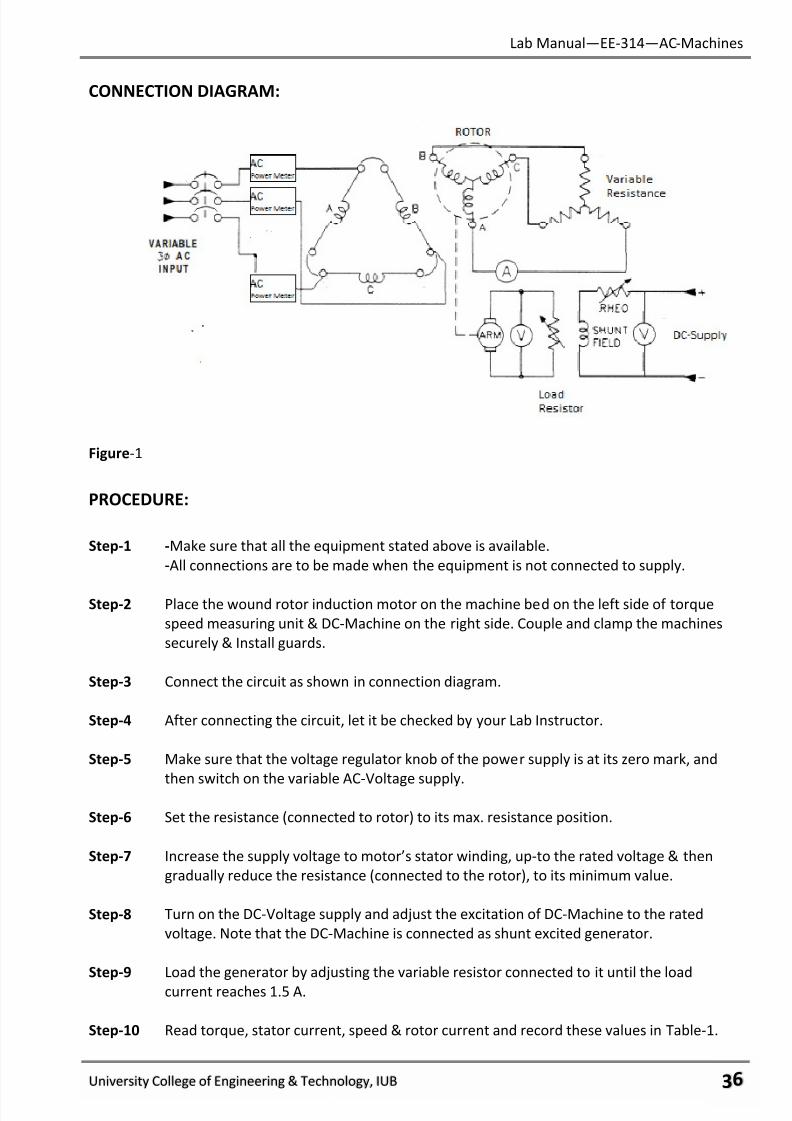
CONNECTION DIAGRAM:
Figure-1
PROCEDURE:
Step-1 -Make sure that all the equipment stated above is available.
-All connections are to be made when the equipment is not connected to supply.
Step-2 Place the wound rotor induction motor on the machine bed on the left side of torque
speed measuring unit & DC-Machine on the right side. Couple and clamp the machines
securely & Install guards.
Step-3 Connect the circuit as shown in connection diagram.
Step-4 After connecting the circuit, let it be checked by your Lab Instructor.
Step-5 Make sure that the voltage regulator knob of the power supply is at its zero mark, and
then switch on the variable AC-Voltage supply.
Step-6 Set the resistance (connected to rotor) to its max. resistance position.
Step-7 Increase the supply voltage to motor’s stator winding, up-to the rated voltage & then
gradually reduce the resistance (connected to the rotor), to its minimum value.
Step-8 Turn on the DC-Voltage supply and adjust the excitation of DC-Machine to the rated
voltage. Note that the DC-Machine is connected as shunt excited generator.
Step-9 Load the generator by adjusting the variable resistor connected to it until the load
current reaches 1.5 A.
Step-10 Read torque, stator current, speed & rotor current and record these values in Table-1.
7/27/2019 AC Electric Machines Lab manul
http://slidepdf.com/reader/full/ac-electric-machines-lab-manul 39/98
Lab Manual—EE-314—AC-Machines
University College of Engineering & Technology, IUB χϋ
Step-11 Now increase the resistance (connected to rotor), to 10 Ω & by keeping the load
constant, repeat step-11.
Step-12 Increase rotor resistance in steps to 15 Ω & 20 Ω and for each step, record the
corresponding values of torque, stator current, speed and rotor current in Table-1.
Step-13 With rotor resistance at its max position (20 Ω), record the speed in Table-2.
Step-14 Reduce the load on the generator in steps & record motor speed in Table-2 as per given
load current.
Step-15 Repeat step-14 with rotor resistance at its minimum position.
Step-16 Turn OFF all circuit breakers. Disconnect all leads.
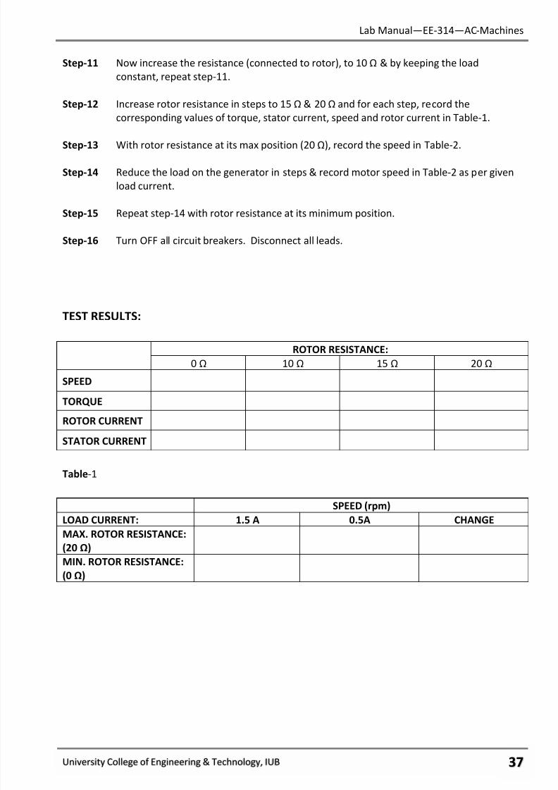
TEST RESULTS:
ROTOR RESISTANCE:
0 Ω 10 Ω 15 Ω 20 Ω
SPEED
TORQUE
ROTOR CURRENT
STATOR CURRENT
Table-1
SPEED (rpm)
LOAD CURRENT: 1.5 A 0.5A CHANGE
MAX. ROTOR RESISTANCE:
(20 Ω)
MIN. ROTOR RESISTANCE:
(0 Ω)
7/27/2019 AC Electric Machines Lab manul
http://slidepdf.com/reader/full/ac-electric-machines-lab-manul 40/98
Lab Manual—EE-314—AC-Machines
University College of Engineering & Technology, IUB χό
REVIEW QUESTIONS:
1. As you added resistance externally to the rotor circuit, while the load remained constant,
what happened to the rotor speed and why?
____________________________________________________________________________
____________________________________________________________________________
____________________________________________________________________________
2. As rotor speed decreased, what happened to the current being inducted into the rotor &
why?
____________________________________________________________________________
____________________________________________________________________________
____________________________________________________________________________
3. As rotor speed decreased, what happened to the current being inducted into the rotor &
why?
____________________________________________________________________________
____________________________________________________________________________
____________________________________________________________________________
4. Compute the change in speed (in Table-2) due to change in load step. Do this for both max.
resistance & zero resistance.
____________________________________________________________________________ ____________________________________________________________________________
____________________________________________________________________________
5. An increase in the external rotor resistance:
a. Increase wound-rotor motor speed.
b. Decrease wound-rotor motor speed.
c. Has no effect on wound-rotor motor speed.
6. When the rotor slows down, the rotor frequency:
a. Goes up.
b. Goes down.
c. Remains the same.
7. With resistance in the rotor circuit, as load changes:
a. There is no change in speed at all.b. There is a slight change in speed.
c. There is a noticeable change in speed.
7/27/2019 AC Electric Machines Lab manul
http://slidepdf.com/reader/full/ac-electric-machines-lab-manul 41/98
Lab Manual—EE-314—AC-Machines
University College of Engineering & Technology, IUB χύ
8. The larger the rotor resistance:
a. The less the rotor current.
b. The greater the rotor current.
c. No effect on rotor current.
9. Wound rotor motors are usually:
a. Started without external resistance in the rotor circuit, then cut in as the motor speeds up.
b. Started with some external resistance in the rotor circuit, then cut inemor as the motor
speeds up.
c. Started with maximum external resistance in the rotor circuit, then cut out as the motor
speeds up.
FINAL CHECKLIST:
1. Clean your equipment/materials and work benches before you leave.
2. Return all equipment and materials to their proper storage area.
3. Submit your answers to the questions, together with your data, calculations, and results
before the next laboratory session.
____________
Signature:
Lab Instructor
7/27/2019 AC Electric Machines Lab manul
http://slidepdf.com/reader/full/ac-electric-machines-lab-manul 42/98
Lab Manual—EE-314—AC-Machines
University College of Engineering & Technology, IUB ψτ
EXPERIMENT # 9:
LOSSES AND EFFICIENCY OF INDUCTION MOTORS
PERFORMANCE OBJECTIVES:
Upon successful completion of this experiment the student will be able to:
1. Perform locked rotor tests and determine the equivalent resistance of induction motors.
2. Explain the source of losses and compute efficiency induction motors.
DISCUSSION:
There are two major classifications of losses in induction motors. The first is the copperlosses. These losses are electrical in nature and are due not only to the stator resistance, but the
referred resistance of the rotor as well the total equivalent resistance of the motor. It is this
equivalent resistance that must be multiplied times the current squared to determine the I2R copper
losses.
To find the equivalent resistance of a motor you must perform a “locked rotor” test. In this
test, the rotor of the induction motor is locked so that it cannot move. In this condition, there
cannot be any rotational losses. All of the electrical power must therefore be lost electrically. The
voltage is slowly increased until rated current flows. The power measurement at that point is used
to compute the equivalent resistance.
The second classification of losses is the rotational losses. Although you could use torque and
speed measurements to compute these losses, it is easier to measure the power input to an
unloaded motor. This power is made up of (1) the no-load copper losses plus (2) the rotational
losses. You can use the no-load current and the equivalent resistance to compute the no-load
copper losses. By subtracting this from the total power in, you have rotational losses.
Rotational losses tend to change with speed. However, speed you can consider them constant.
EQUIPMENT:
• Induction Motor (Squirrel-Cage)
• DC Machine (operating as DC-Generator.)
• Torque Speed Measuring Unit.
• Variable Power Supply.
• AC-Power Meters.
• Digital Multi-Meters
• Resistive load.• Connecting Leads.
7/27/2019 AC Electric Machines Lab manul
http://slidepdf.com/reader/full/ac-electric-machines-lab-manul 43/98
Lab Manual—EE-314—AC-Machines
University College of Engineering & Technology, IUB ψυ
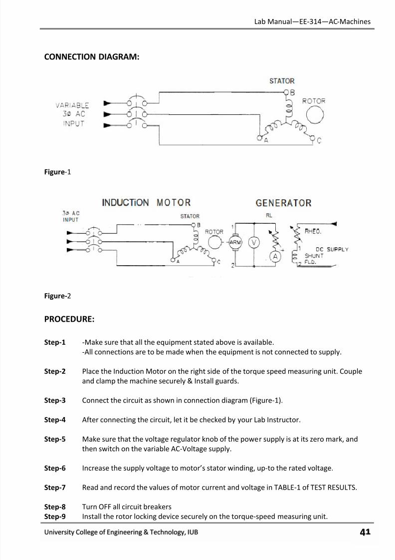
CONNECTION DIAGRAM:
Figure-1
Figure-2
PROCEDURE:
Step-1 -Make sure that all the equipment stated above is available.
-All connections are to be made when the equipment is not connected to supply.
Step-2 Place the Induction Motor on the right side of the torque speed measuring unit. Couple
and clamp the machine securely & Install guards.
Step-3 Connect the circuit as shown in connection diagram (Figure-1).
Step-4 After connecting the circuit, let it be checked by your Lab Instructor.
Step-5 Make sure that the voltage regulator knob of the power supply is at its zero mark, and
then switch on the variable AC-Voltage supply.
Step-6 Increase the supply voltage to motor’s stator winding, up-to the rated voltage.
Step-7 Read and record the values of motor current and voltage in TABLE-1 of TEST RESULTS.
Step-8 Turn OFF all circuit breakers
Step-9 Install the rotor locking device securely on the torque-speed measuring unit.
7/27/2019 AC Electric Machines Lab manul
http://slidepdf.com/reader/full/ac-electric-machines-lab-manul 44/98
Lab Manual—EE-314—AC-Machines
University College of Engineering & Technology, IUB ψφ
Step-10 Make sure that the voltage regulator knob of the power supply is at its zero mark, and
then switch on the variable AC-Voltage supply.
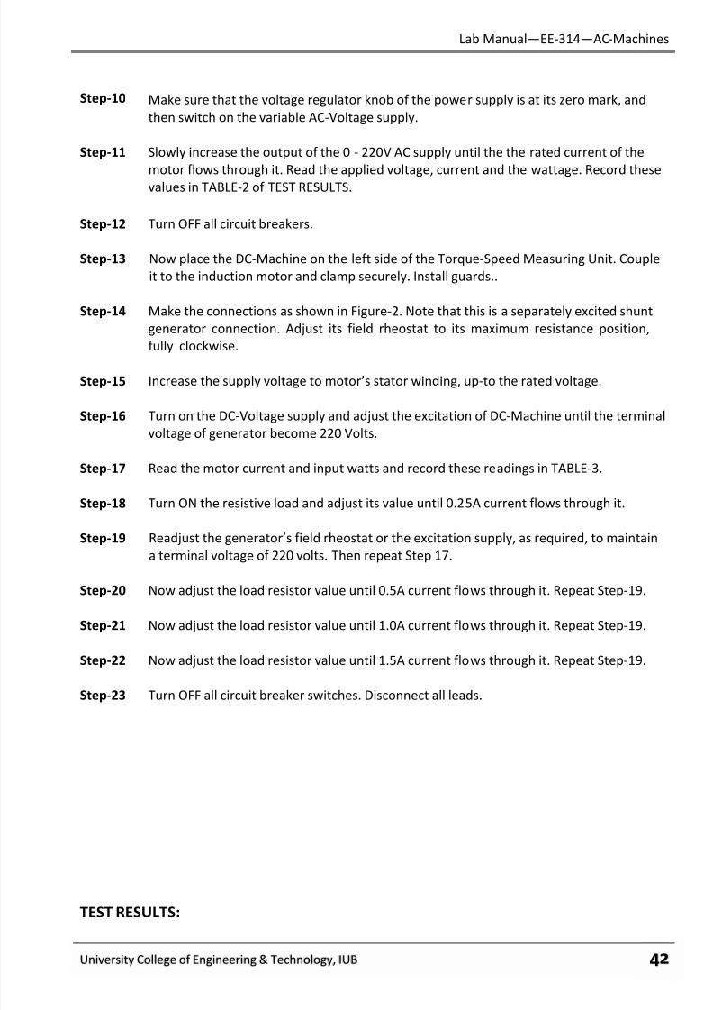
Step-11 Slowly increase the output of the 0 - 220V AC supply until the the rated current of the
motor flows through it. Read the applied voltage, current and the wattage. Record these
values in TABLE-2 of TEST RESULTS.
Step-12 Turn OFF all circuit breakers.
Step-13 Now place the DC-Machine on the left side of the Torque-Speed Measuring Unit. Couple
it to the induction motor and clamp securely. Install guards..
Step-14 Make the connections as shown in Figure-2. Note that this is a separately excited shunt
generator connection. Adjust its field rheostat to its maximum resistance position,
fully clockwise.
Step-15 Increase the supply voltage to motor’s stator winding, up-to the rated voltage.
Step-16 Turn on the DC-Voltage supply and adjust the excitation of DC-Machine until the terminal
voltage of generator become 220 Volts.
Step-17 Read the motor current and input watts and record these readings in TABLE-3.
Step-18 Turn ON the resistive load and adjust its value until 0.25A current flows through it.
Step-19 Readjust the generator’s field rheostat or the excitation supply, as required, to maintain
a terminal voltage of 220 volts. Then repeat Step 17.
Step-20 Now adjust the load resistor value until 0.5A current flows through it. Repeat Step-19.
Step-21 Now adjust the load resistor value until 1.0A current flows through it. Repeat Step-19.
Step-22 Now adjust the load resistor value until 1.5A current flows through it. Repeat Step-19.
Step-23 Turn OFF all circuit breaker switches. Disconnect all leads.
TEST RESULTS:
7/27/2019 AC Electric Machines Lab manul
http://slidepdf.com/reader/full/ac-electric-machines-lab-manul 45/98
Lab Manual—EE-314—AC-Machines
University College of Engineering & Technology, IUB ψχ
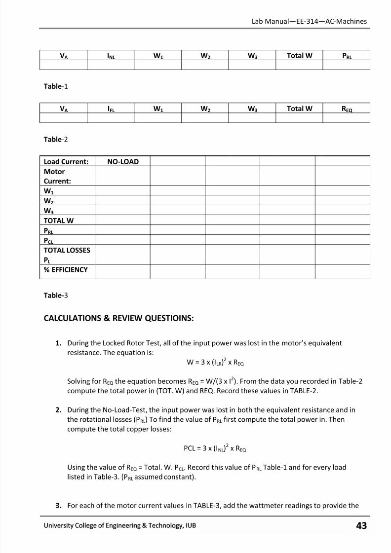
VA INL W1 W2 W3 Total W PRL
Table-1
VA IFL W1 W2 W3 Total W REQ
Table-2
Load Current: NO-LOAD
Motor
Current:
W1 W2
W3
TOTAL W
PRL
PCL
TOTAL LOSSES
PL
% EFFICIENCY
Table-3
CALCULATIONS & REVIEW QUESTIOINS:
1. During the Locked Rotor Test, all of the input power was lost in the motor’s equivalent
resistance. The equation is:
W = 3 x (ILR)2
x REQ
Solving for REQ the equation becomes REQ = W/(3 x I2). From the data you recorded in Table-2
compute the total power in (TOT. W) and REQ. Record these values in TABLE-2.
2. During the No-Load-Test, the input power was lost in both the equivalent resistance and in
the rotational losses (PRL) To find the value of PRL first compute the total power in. Then
compute the total copper losses:
PCL = 3 x (INL)2
x REQ
Using the value of REQ = Total. W. PCL. Record this value of PRL Table-1 and for every load
listed in Table-3. (PRL assumed constant).
3. For each of the motor current values in TABLE-3, add the wattmeter readings to provide the
7/27/2019 AC Electric Machines Lab manul
http://slidepdf.com/reader/full/ac-electric-machines-lab-manul 46/98
Lab Manual—EE-314—AC-Machines
University College of Engineering & Technology, IUB ψψ
total power in. Record these values in TABLE-3.
4. For each of the motor current values in TABLE 16-3 compute the total copper loss from the
equation PCL = 3 x x REQ using the value of REQ from TABLE-2. Record the copper loss values
in TABLE-3. Add each of these values to the value computed in No. 2 to produce the
total loss value for each of the loads. Record these values in TABLE 16-3.
5. Compute efficiency, the ratio of output power to input power. For output power subtract
the losses from the output power. The equation is:
% Efficiency = Total Watts in - PL x 100
Total Watts in
List these efficiencies in TABLE-3.
6.
As load increases, rotational losses:
a. Increase.
b. Decrease.
c. Remain the same.
7. As load increases, copper losses:
a. Increase.
b. Decrease.
c. Remain the same.
8. As load increases, the total losses become:
a. A larger share of the total power in.
b. A smaller share of the total power in.
c. The same share of the total power in.
9. As load increase, the motor:
a. Operates more efficiently.b. Operates less efficiently.
c. Operates with the same efficiency.
10. Power Out equals:
a. The power in.
b. The total of copper and rotational losses.
c. The power in minus the total losses.

7/27/2019 AC Electric Machines Lab manul
http://slidepdf.com/reader/full/ac-electric-machines-lab-manul 47/98
Lab Manual—EE-314—AC-Machines
University College of Engineering & Technology, IUB ψω
FINAL CHECKLIST:
1. Clean your equipment/materials and work benches before you leave.
2. Return all equipment and materials to their proper storage area.
3. Submit your answers to the questions, together with your data, calculations, and results
before the next laboratory session.
____________
Signature:
Lab Instructor
7/27/2019 AC Electric Machines Lab manul
http://slidepdf.com/reader/full/ac-electric-machines-lab-manul 48/98
Lab Manual—EE-314—AC-Machines
University College of Engineering & Technology, IUB ψϊ
EXPERIMENT # 10:
SATURATION CURVE OF AN ALTERNATOR.
PERFORMANCE OBJECTIVES:
Upon successful completion of this experiment the student will be able to:
1. Describe how voltage is generated in an armature and the effect of field current.
2. Perform saturation tests on alternators & to discover the effect of saturation on the terminal
voltage of an alternator.
DISCUSSION:
Alternators are designed to run at a specific speed (known as synchronous speed) to produce
voltage at a specific frequency. That’s why they are referred to as “synchronous alternators”.
Alternators are driven at synchronous speed by a prime mover. Typical prime movers are diesel
engines, jet engines, steam turbines, hydro-turbines, and DC motors.
The field coil of a synchronous alternator is wound on a rotor, which has salient poles. The
laminated iron core is called the “spider”. The armature coils are imbedded in slots on the stator. As
the rotor (field) is driven, its magnetic field sweeps around inside the housing. This moving field is
cut by the turns of the armature coil of the stator. This induces a voltage into the armature coils.
The amount of voltage induced depends on two things: (1) the speed of the rotor and (2) the
strength of the magnetic field. Magnetic field strength, in turn, depends on the amount of current
passing through the field coil. As the current increases, so does the field strength up to a point. That
point we call saturation. When the spider becomes magnetically saturated, further increase of field
current produce little or no further increase of field strength. Thus, the alternator’s terminal voltage
levels off.
EQUIPMENT:
• DC Machine (operating as a motor.)
• Synchronous Machine (operating as an alternator.)
• Torque Speed Measuring Unit.
• Variable AC Supply.
• AC-Power Meters.
• Connecting Leads.
7/27/2019 AC Electric Machines Lab manul
http://slidepdf.com/reader/full/ac-electric-machines-lab-manul 49/98
Lab Manual—EE-314—AC-Machines
University College of Engineering & Technology, IUB ψϋ
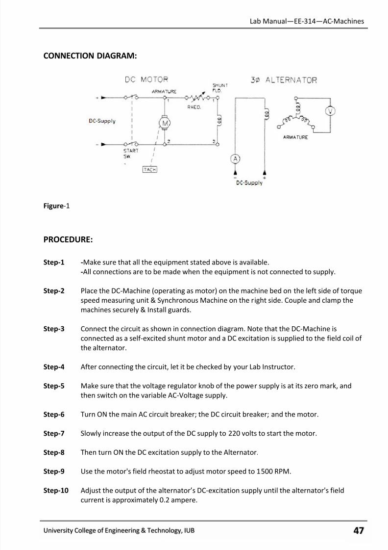
CONNECTION DIAGRAM:
Figure-1
PROCEDURE:
Step-1 -Make sure that all the equipment stated above is available.
-All connections are to be made when the equipment is not connected to supply.
Step-2 Place the DC-Machine (operating as motor) on the machine bed on the left side of torquespeed measuring unit & Synchronous Machine on the right side. Couple and clamp the
machines securely & Install guards.
Step-3 Connect the circuit as shown in connection diagram. Note that the DC-Machine is
connected as a self-excited shunt motor and a DC excitation is supplied to the field coil of
the alternator.
Step-4 After connecting the circuit, let it be checked by your Lab Instructor.
Step-5 Make sure that the voltage regulator knob of the power supply is at its zero mark, andthen switch on the variable AC-Voltage supply.
Step-6 Turn ON the main AC circuit breaker; the DC circuit breaker; and the motor.
Step-7 Slowly increase the output of the DC supply to 220 volts to start the motor.
Step-8 Then turn ON the DC excitation supply to the Alternator.
Step-9 Use the motor's field rheostat to adjust motor speed to 1500 RPM.
Step-10 Adjust the output of the alternator’s DC-excitation supply until the alternator's field
current is approximately 0.2 ampere.
7/27/2019 AC Electric Machines Lab manul
http://slidepdf.com/reader/full/ac-electric-machines-lab-manul 50/98
Lab Manual—EE-314—AC-Machines
University College of Engineering & Technology, IUB ψό
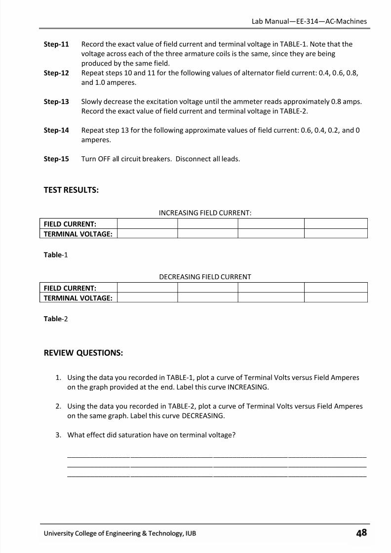
Step-11 Record the exact value of field current and terminal voltage in TABLE-1. Note that the
voltage across each of the three armature coils is the same, since they are being
produced by the same field.
Step-12 Repeat steps 10 and 11 for the following values of alternator field current: 0.4, 0.6, 0.8,
and 1.0 amperes.
Step-13 Slowly decrease the excitation voltage until the ammeter reads approximately 0.8 amps.
Record the exact value of field current and terminal voltage in TABLE-2.
Step-14 Repeat step 13 for the following approximate values of field current: 0.6, 0.4, 0.2, and 0
amperes.
Step-15 Turn OFF all circuit breakers. Disconnect all leads.
TEST RESULTS:
INCREASING FIELD CURRENT:
FIELD CURRENT:
TERMINAL VOLTAGE:
Table-1
DECREASING FIELD CURRENT
FIELD CURRENT:TERMINAL VOLTAGE:
Table-2
REVIEW QUESTIONS:
1. Using the data you recorded in TABLE-1, plot a curve of Terminal Volts versus Field Amperes
on the graph provided at the end. Label this curve INCREASING.
2. Using the data you recorded in TABLE-2, plot a curve of Terminal Volts versus Field Amperes
on the same graph. Label this curve DECREASING.
3. What effect did saturation have on terminal voltage?
____________________________________________________________________________
____________________________________________________________________________
____________________________________________________________________________

7/27/2019 AC Electric Machines Lab manul
http://slidepdf.com/reader/full/ac-electric-machines-lab-manul 51/98
Lab Manual—EE-314—AC-Machines
University College of Engineering & Technology, IUB ψύ
4. From your observations would you regard residual magnetism in the rotor core an important
or unimportant factor? What led you to this conclusion?
____________________________________________________________________________
____________________________________________________________________________
____________________________________________________________________________
5. Why is it good to use low hysteresis material for the rotor core?
____________________________________________________________________________
____________________________________________________________________________
____________________________________________________________________________
6. Induced (generated) voltage in an alternator results from:
a. A stationary field and moving conductors.
b. A moving field and stationary conductors.
c. Both moving field and moving conductors.
7. You cannot have a self-excited alternator without rectifying the AC output, because:
a. The field poles must be constant North-South.
b. There is not enough residual magnetism to begin the generating process.
c. Armature coils must have DC applied to them.
8. Below the saturation point, as field current increases, terminal voltage:
a. Increases in direct proportion.
b. Decreases in direct proportion.
c. Stays the same.
9. Above saturation, increases in field current produce:
a. Larger increase in terminal voltage.
b. Smaller increases in terminal voltage.
c. No difference in terminal voltage.
10. When running at a constant speed, the terminal voltage of an alternator can be changed by:
a. Reversing the polarity of the field
b. Changing the direction of rotation.
c. Changing field current.

7/27/2019 AC Electric Machines Lab manul
http://slidepdf.com/reader/full/ac-electric-machines-lab-manul 52/98
Lab Manual—EE-314—AC-Machines
University College of Engineering & Technology, IUB ωτ
GRAPH:

7/27/2019 AC Electric Machines Lab manul
http://slidepdf.com/reader/full/ac-electric-machines-lab-manul 53/98
Lab Manual—EE-314—AC-Machines
University College of Engineering & Technology, IUB ωυ
FINAL CHECKLIST:
1. Clean your equipment/materials and work benches before you leave.
2. Return all equipment and materials to their proper storage area.
3. Submit your answers to the questions, together with your data, calculations, and results
before the next laboratory session.
____________
Signature:
Lab Instructor
7/27/2019 AC Electric Machines Lab manul
http://slidepdf.com/reader/full/ac-electric-machines-lab-manul 54/98
Lab Manual—EE-314—AC-Machines
University College of Engineering & Technology, IUB ωφ
EXPERIMENT # 11:
EFFECT OF SPEED ON ALTERNATOR.
PERFORMANCE OBJECTIVES:
Upon successful completion of this experiment the student will be able to:
1. Discover the effect of speed on the terminal voltage and frequency of generated voltage &
vary the output voltage and frequency of an alternator by changing speed.
2. Compute alternator frequency, given the number of poles and speed.
DISCUSSION:
The armature coils of an alternator are wound on the stator. There are no salient poles on
the stator; the conductors are imbedded into slots. The coils are arranged into distinct coil groups.
These coil groups are arranged on the stator to produce three-phase power. The coils are known as
A, B, and C.
Assume the magnetic field from the rotor is sweeping around. As it passes under Phase A
coil, Phase A voltage is at peak. 120 electrical degrees later, it passed under Phase B coil. Then, 120
electrical degrees later, it passes under Phase C coil. If there is only one group of three coils on the
stator, a full cycle is completed during one revolution of the rotor.
The rotor has one pair of salient poles (north and south) for each coil group on the stator. An
alternator is known by the number of rotor poles. Thus, the lowest number is 2. We call that a two-
pole alternator. The induction motor in our lab is a four pole machine. That means that two cycles of
AC are produced each time the rotor completes one revolution.
The frequency of the output voltage depends on the number of poles and the speed at
which the rotor is being driven.
Frequency (Hertz) = Speed (RPM) x (1minute/60seconds) x no. of pairs of poles
For example, a 2-pole (1 pair of poles) alternator driven at 3600 RPM has a frequency of
60Hz.
Speed affects terminal voltage also. The faster the rotor is driven, the faster the magnetic flux
lines get cut by the stationary armature conductors. Therefore, the larger the terminal voltage for
the same field current.
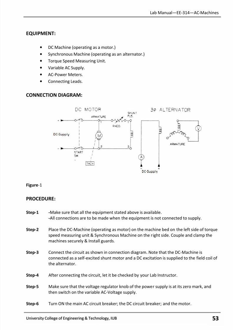
7/27/2019 AC Electric Machines Lab manul
http://slidepdf.com/reader/full/ac-electric-machines-lab-manul 55/98
Lab Manual—EE-314—AC-Machines
University College of Engineering & Technology, IUB ωχ
EQUIPMENT:
• DC Machine (operating as a motor.)
• Synchronous Machine (operating as an alternator.)
• Torque Speed Measuring Unit.
• Variable AC Supply.
• AC-Power Meters.
• Connecting Leads.
CONNECTION DIAGRAM:
Figure-1
PROCEDURE:
Step-1 -Make sure that all the equipment stated above is available.
-All connections are to be made when the equipment is not connected to supply.
Step-2 Place the DC-Machine (operating as motor) on the machine bed on the left side of torquespeed measuring unit & Synchronous Machine on the right side. Couple and clamp the
machines securely & Install guards.
Step-3 Connect the circuit as shown in connection diagram. Note that the DC-Machine is
connected as a self-excited shunt motor and a DC excitation is supplied to the field coil of
the alternator.
Step-4 After connecting the circuit, let it be checked by your Lab Instructor.
Step-5 Make sure that the voltage regulator knob of the power supply is at its zero mark, and
then switch on the variable AC-Voltage supply.
Step-6 Turn ON the main AC circuit breaker; the DC circuit breaker; and the motor.
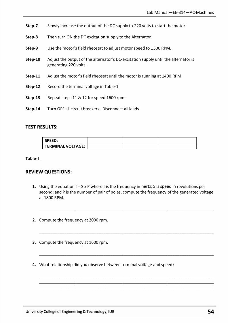
7/27/2019 AC Electric Machines Lab manul
http://slidepdf.com/reader/full/ac-electric-machines-lab-manul 56/98
Lab Manual—EE-314—AC-Machines
University College of Engineering & Technology, IUB ωψ
Step-7 Slowly increase the output of the DC supply to 220 volts to start the motor.
Step-8 Then turn ON the DC excitation supply to the Alternator.
Step-9 Use the motor's field rheostat to adjust motor speed to 1500 RPM.
Step-10 Adjust the output of the alternator’s DC-excitation supply until the alternator is
generating 220 volts.
Step-11 Adjust the motor’s field rheostat until the motor is running at 1400 RPM.
Step-12 Record the terminal voltage in Table-1
Step-13 Repeat steps 11 & 12 for speed 1600 rpm.
Step-14 Turn OFF all circuit breakers. Disconnect all leads.
TEST RESULTS:
SPEED:
TERMINAL VOLTAGE:
Table-1
REVIEW QUESTIONS:
1. Using the equation f = S x P where f is the frequency in hertz; S is speed in revolutions per
second; and P is the number of pair of poles, compute the frequency of the generated voltage
at 1800 RPM.
____________________________________________________________________________
2. Compute the frequency at 2000 rpm.
____________________________________________________________________________
3. Compute the frequency at 1600 rpm.
____________________________________________________________________________
4. What relationship did you observe between terminal voltage and speed?
____________________________________________________________________________
____________________________________________________________________________ ____________________________________________________________________________
7/27/2019 AC Electric Machines Lab manul
http://slidepdf.com/reader/full/ac-electric-machines-lab-manul 57/98
Lab Manual—EE-314—AC-Machines
University College of Engineering & Technology, IUB ωω
5. Is it better to energize the alternator’s field before or after it reaches full speed? What led
you to this conclusion?
____________________________________________________________________________
____________________________________________________________________________
____________________________________________________________________________
6. When speed increases, the frequency:
a. Increases
b. Decreases
c. Remains the same
7. When Speed increases, the terminal voltage:
a. Increases
b. Decreases
c. Remains the same
8. To obtain a higher terminal voltage at the same frequency, you should increase:
a. Speed.
b. Armature Resistance
c. Field Current.
9. The terminal voltage of an alternator depends on:
a. Direction of Rotation.
b. Direction of Field Current.
c. Speed and Field Current.
10. In three-phase power, each phase voltage lags behind the one in front of it by:
a. 30 Electrical Degrees
b. 120 Electrical Degrees.
c. 360 Electrical Degrees.
FINAL CHECKLIST:
1. Clean your equipment/materials and work benches before you leave.
2. Return all equipment and materials to their proper storage area.
3. Submit your answers to the questions, together with your data, calculations, and results
before the next laboratory session.
____________
Signature:
Lab Instructor
7/27/2019 AC Electric Machines Lab manul
http://slidepdf.com/reader/full/ac-electric-machines-lab-manul 58/98
Lab Manual—EE-314—AC-Machines
University College of Engineering & Technology, IUB ωϊ
EXPERIMENT # 12:
LOAD CHARACTERISTICS OF AN ALTERNATOR.
PERFORMANCE OBJECTIVES:
Upon successful completion of this experiment the student will be able to:
1. Explain why loading has an effect on terminal voltage. 2. Differentiate between unity, lagging, and leading power factor loads.
DISCUSSION:
If there is no load on an alternator, its terminal voltage depends solely on speed and field
current. However, load current flows through the armature coils making terminal voltage depend on
the nature of the load. In this experiment we will maintain a constant speed and a constant field
current while loading the alternator with a unity, leading, and lagging loads.
There are three reasons why terminal voltage is different from that generated. First is
armature resistance. Second is armature reaction. Third is armature reactance.
With a resistive (unity power factor) load, there is the voltage drop due to the armature coil’s
resistance. This IR drop increases as the load increases. Also there is the inductance of the armature
coil. This increases as the load increases. Armature reaction is the effect that the magnetic field of
the armature has on the main rotor field. It weakens the main field reducing the generated voltage.
It, too, acts like a voltage drop, increasing as the load increases.
When the load is inductive (lagging power factor) all three elements are still present.
However, the load current is already lagging terminal voltage. This doesn’t change the IR drop but it
does increase the effects of armature reactance and armature reaction.
With a capacitive (leading power factor) load, there is a completely different situation. You
still have the IR drop due to resistance, but the adds to the generated voltage instead of
subtracting from it. From Lenz’s law we know that inductive reactance tends to oppose whatever
causes it. Its cause in the alternator is the load current. The load current, however, leads the
generated voltage. If the angle of lead is great enough, the coil’s back-voltage (which is where
inductive reactance comes from) makes the terminal voltage larger than the generated voltage.
Armature reaction helps too. Instead of weakening the main field, it strengthens it. Therefore, with a
leading power factor load, terminal voltage increases as the load increases. Voltage regulation (V.R.)
is the ratio between the total drop in voltage and the full load voltage. The equation is:
% V.R. =No-load volts - Full load volts x 100
Full load volts
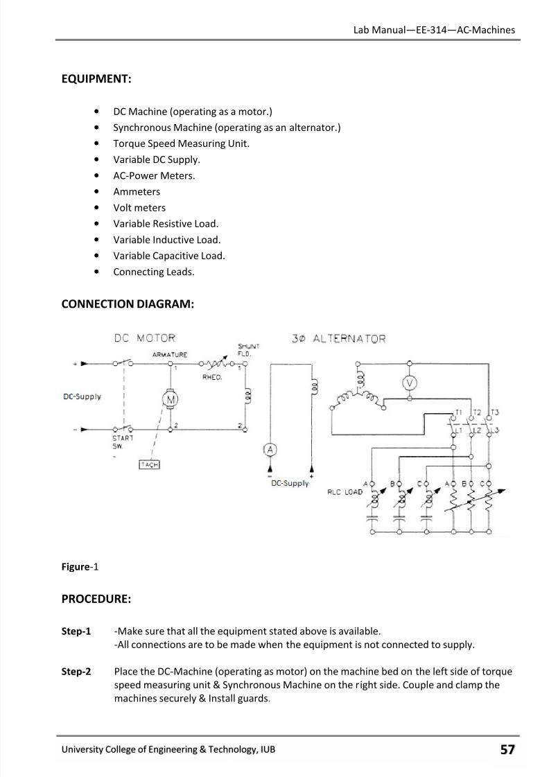
7/27/2019 AC Electric Machines Lab manul
http://slidepdf.com/reader/full/ac-electric-machines-lab-manul 59/98
Lab Manual—EE-314—AC-Machines
University College of Engineering & Technology, IUB ωϋ
EQUIPMENT:
• DC Machine (operating as a motor.)
• Synchronous Machine (operating as an alternator.)
• Torque Speed Measuring Unit.
• Variable DC Supply.
• AC-Power Meters.
• Ammeters
• Volt meters
• Variable Resistive Load.
• Variable Inductive Load.
• Variable Capacitive Load.
• Connecting Leads.
CONNECTION DIAGRAM:
Figure-1
PROCEDURE:
Step-1 -Make sure that all the equipment stated above is available.
-All connections are to be made when the equipment is not connected to supply.
Step-2 Place the DC-Machine (operating as motor) on the machine bed on the left side of torque
speed measuring unit & Synchronous Machine on the right side. Couple and clamp the
machines securely & Install guards.
7/27/2019 AC Electric Machines Lab manul
http://slidepdf.com/reader/full/ac-electric-machines-lab-manul 60/98
Lab Manual—EE-314—AC-Machines
University College of Engineering & Technology, IUB ωό
Step-3 Connect the circuit as shown in connection diagram. Note that the DC-Machine is
connected as a self-excited shunt motor and a DC excitation is supplied to the field coil of
the alternator. Connect the RLC load to the alternator’s terminals.
Step-4 After connecting the circuit, let it be checked by your Lab Instructor.
Step-5 Make sure that the voltage regulator knob of the power supply is at its zero mark, and
then switch on the variable DC-Voltage supply.
Step-6 Turn ON the main DC circuit breaker; the DC circuit breaker; and the motor.
Step-7 Slowly increase the output of the DC supply to 220 volts to start the motor.
Step-8 Then turn ON the DC excitation supply to the Alternator.
Step-9 Use the motor's field rheostat to adjust motor speed to 1500 RPM.
Step-10 Adjust the output of the alternator’s DC-excitation supply until the alternator is
generating 220 volts.
Step-11 Turn on the resistive load & increase it gradually until the rated current flows through the
alternator stator windings. Re-adjust the alternator’s excitation supply until the
alternator’s terminal voltages are exactly 220 Volts.
Step-12 Repeat Steps 9 and 10 as necessary until the full load terminal volts of the alternator is
exactly 220 volts at 1500 RPM. (Note that the load should also be varied accordingly in
order to keep the load current equal to the alternator’s rated current.)
Step-13 Record the full load terminals as 220 Volts in Table-1.
Step-14 Remove the load from alternator terminals and repeat Step-9 to re-adjust motor speed
to 1500 RPM.
Step-15 Read the no-load terminal voltages at the alternator terminals and record these values in
Table-1.
Step-16 Connect the inductive load (2-steps) to alternator terminals in parallel with alreadyconnected resistive load, to produce lagging power factor and vary the resistive load
accordingly until the rated current flows through the alternator terminals.
Step-17 Repeat Steps 9 and 10 as necessary until the full load terminal volts of the alternator is
exactly 220 volts at 1500 RPM. (Note that the load should also be varied accordingly in
order to keep the load current equal to the alternator’s rated current.)
Step-18 Record the full load terminals as 220 Volts in Table-1.
Step-19 Remove the load from alternator terminals and repeat Step-9 to re-adjust motor speedto 1500 RPM.
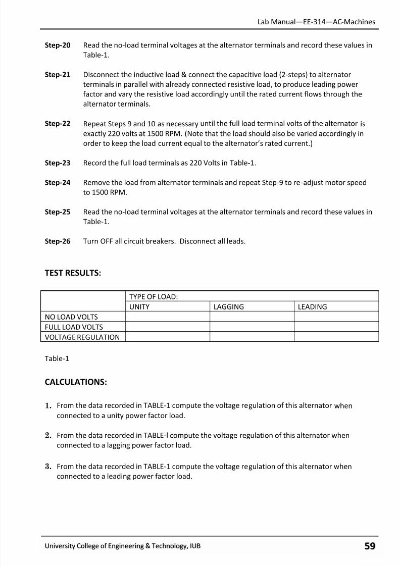
7/27/2019 AC Electric Machines Lab manul
http://slidepdf.com/reader/full/ac-electric-machines-lab-manul 61/98
Lab Manual—EE-314—AC-Machines
University College of Engineering & Technology, IUB ωύ
Step-20 Read the no-load terminal voltages at the alternator terminals and record these values in
Table-1.
Step-21 Disconnect the inductive load & connect the capacitive load (2-steps) to alternator
terminals in parallel with already connected resistive load, to produce leading power
factor and vary the resistive load accordingly until the rated current flows through the
alternator terminals.
Step-22 Repeat Steps 9 and 10 as necessary until the full load terminal volts of the alternator is
exactly 220 volts at 1500 RPM. (Note that the load should also be varied accordingly in
order to keep the load current equal to the alternator’s rated current.)
Step-23 Record the full load terminals as 220 Volts in Table-1.
Step-24 Remove the load from alternator terminals and repeat Step-9 to re-adjust motor speed
to 1500 RPM.
Step-25 Read the no-load terminal voltages at the alternator terminals and record these values in
Table-1.
Step-26 Turn OFF all circuit breakers. Disconnect all leads.
TEST RESULTS:
TYPE OF LOAD:UNITY LAGGING LEADING
NO LOAD VOLTS
FULL LOAD VOLTS
VOLTAGE REGULATION
Table-1
CALCULATIONS:
1. From the data recorded in TABLE-1 compute the voltage regulation of this alternator when
connected to a unity power factor load.
2. From the data recorded in TABLE-l compute the voltage regulation of this alternator when
connected to a lagging power factor load.
3. From the data recorded in TABLE-1 compute the voltage regulation of this alternator when
connected to a leading power factor load.

7/27/2019 AC Electric Machines Lab manul
http://slidepdf.com/reader/full/ac-electric-machines-lab-manul 62/98
Lab Manual—EE-314—AC-Machines
University College of Engineering & Technology, IUB ϊτ
REVIEW QUESTIONS:
1. From your observations, was the percentage voltage regulation better or poorer when a reactive
load was connected? What led you to this conclusion?
_______________________________________________________________________________ _______________________________________________________________________________
_______________________________________________________________________________
2. From your observations, was the percentage voltage regulation better or poorer when a reactive
load was connected? Where does the additional voltage come from?
_______________________________________________________________________________
_______________________________________________________________________________
_______________________________________________________________________________
3. As resistive load is added, terminal voltage:
a. Increases
b. Decreases
c. Remains the same
4. The power factor of the connected load:
a. Affects armature resistance and inductive reactance
b. Affects armature reactance and reaction.
c. Affects armature resistance and reactance.
5. As inductive load increases, terminal voltage:
a. Increases
b. Decreases
c. Remains the same
6. A zero percent voltage regulation means:
a. No-load voltage is greater than full-load voltage
b. No-load voltage is less than full-load voltage
c. No-load voltage is the same as full-load voltage
7/27/2019 AC Electric Machines Lab manul
http://slidepdf.com/reader/full/ac-electric-machines-lab-manul 63/98
Lab Manual—EE-314—AC-Machines
University College of Engineering & Technology, IUB ϊυ
7. As capacitive load increases, terminal voltage:
a. Increases
b. Decreases
c. Remains the same
FINAL CHECKLIST:
1. Clean your equipment/materials and work benches before you leave.
2. Return all equipment and materials to their proper storage area.
3. Submit your answers to the questions, together with your data, calculations, and results
before the next laboratory session.
____________
Signature:
Lab Instructor
7/27/2019 AC Electric Machines Lab manul
http://slidepdf.com/reader/full/ac-electric-machines-lab-manul 64/98
Lab Manual—EE-314—AC-Machines
University College of Engineering & Technology, IUB ϊφ
EXPERIMENT # 13:
LOSSES & EFFICIENCY OF AN ALTERNATOR.
PERFORMANCE OBJECTIVES:
Upon successful completion of this experiment the student will be able to:
1. Identify the sources of losses in alternators.
2. Compute efficiency given the power out and the magnitude of the losses.
DISCUSSION:
Whenever we convert one form of energy into another there are bound to be losses. No
machine is perfect. Power is supplied to an alternator both in the form of electrical energy and in
the form of mechanical energy. The electrical energy is supplied to the field coil. This energy is used
to set up the main magnetic field. This field is constant. There is no energy taken from it in the
generation of electricity. Therefore, since none of the power out comes from this energy, the power
by the field must be counted as a loss.
Most of the power comes from the prime mover. Some of this mechanical power is lost to
the windings and friction of the alternator. The mechanical losses do not depend on the alternator’s
load. To find these losses, it is necessary to determine the overall mechanical losses then subtract
the losses of the prime mover.
Another class of losses that does not vary with load is the core losses. We are speaking here
about the armature’s core. Since there is an alternating voltage generated, the core is continually
becoming magnetized with one polarity, de-magnetized, then magnetized with the other polarity
each cycle. All of this magnetic activity in the core causes eddy current and hysteresis losses. These
core losses depend on the alternator’s voltage, not on load.
As load current flows through the armature coils the resistance of the wire causes a power
loss. This copper loss is proportional to the square of the current, P=I2R. Copper losses, therefore,
increase rapidly with load.
Percent efficiency is the ratio between the power out and the power in.
% Eff. = x100
If the load has unity power factor,
= V x I x 1.73.
Regardless of load,
= +Losses.
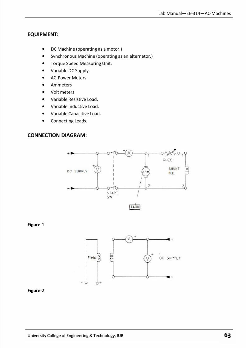
7/27/2019 AC Electric Machines Lab manul
http://slidepdf.com/reader/full/ac-electric-machines-lab-manul 65/98
Lab Manual—EE-314—AC-Machines
University College of Engineering & Technology, IUB ϊχ
EQUIPMENT:
• DC Machine (operating as a motor.)
• Synchronous Machine (operating as an alternator.)
• Torque Speed Measuring Unit.
• Variable DC Supply.
• AC-Power Meters.
• Ammeters
• Volt meters
• Variable Resistive Load.
• Variable Inductive Load.
• Variable Capacitive Load.
• Connecting Leads.
CONNECTION DIAGRAM:
Figure-1
Figure-2
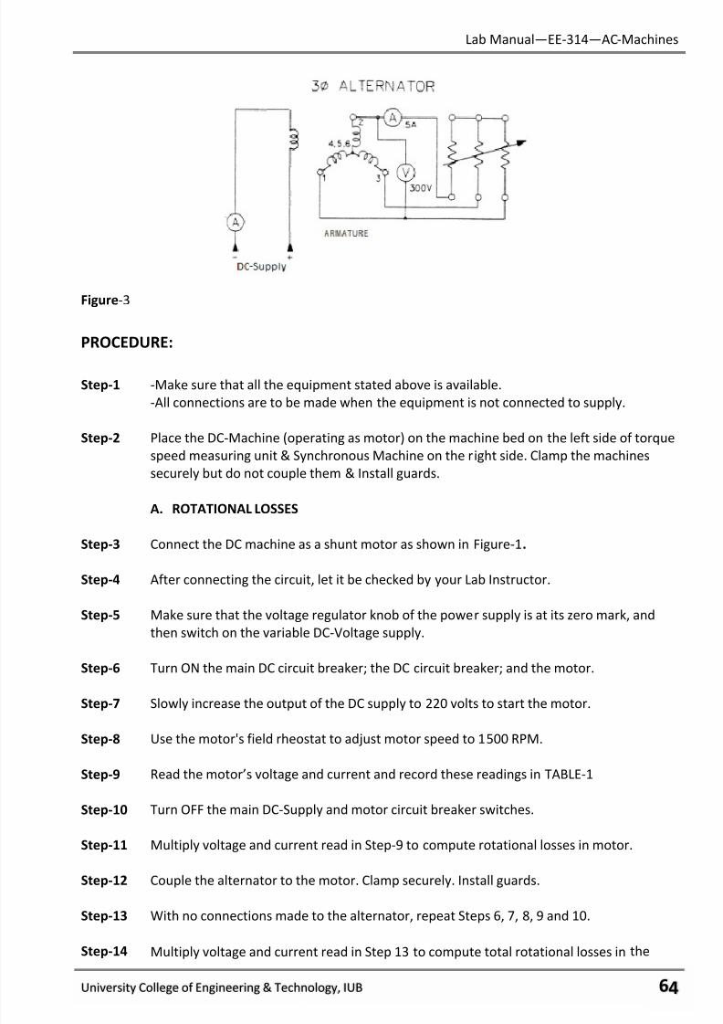
7/27/2019 AC Electric Machines Lab manul
http://slidepdf.com/reader/full/ac-electric-machines-lab-manul 66/98
Lab Manual—EE-314—AC-Machines
University College of Engineering & Technology, IUB ϊψ
Figure-3
PROCEDURE:
Step-1 -Make sure that all the equipment stated above is available.
-All connections are to be made when the equipment is not connected to supply.
Step-2 Place the DC-Machine (operating as motor) on the machine bed on the left side of torque
speed measuring unit & Synchronous Machine on the right side. Clamp the machines
securely but do not couple them & Install guards.
A. ROTATIONAL LOSSES
Step-3 Connect the DC machine as a shunt motor as shown in Figure-1.
Step-4 After connecting the circuit, let it be checked by your Lab Instructor.
Step-5 Make sure that the voltage regulator knob of the power supply is at its zero mark, and
then switch on the variable DC-Voltage supply.
Step-6 Turn ON the main DC circuit breaker; the DC circuit breaker; and the motor.
Step-7 Slowly increase the output of the DC supply to 220 volts to start the motor.
Step-8 Use the motor's field rheostat to adjust motor speed to 1500 RPM.
Step-9 Read the motor’s voltage and current and record these readings in TABLE-1
Step-10 Turn OFF the main DC-Supply and motor circuit breaker switches.
Step-11 Multiply voltage and current read in Step-9 to compute rotational losses in motor.
Step-12 Couple the alternator to the motor. Clamp securely. Install guards.
Step-13 With no connections made to the alternator, repeat Steps 6, 7, 8, 9 and 10.
Step-14 Multiply voltage and current read in Step 13 to compute total rotational losses in the
7/27/2019 AC Electric Machines Lab manul
http://slidepdf.com/reader/full/ac-electric-machines-lab-manul 67/98
Lab Manual—EE-314—AC-Machines
University College of Engineering & Technology, IUB ϊω
motor and alternator, PMAL. Record this value in TABLE-1.
Step-15 Compute the alternator’s rotational losses, PAL by subtracting PML from PMAL
Record in TABLE-1 and TABLE-5.
B. DETERMINE THE ARMATURE RESISTANCE
Step-16 Connect the DC-Supply to one of the alternator’s coils as shown in Figure-2.
Step-17 Make sure that the voltage regulator knob of the power supply is at its zero mark, and
then switch on the variable DC-Voltage supply.
Step-18 Slowly increase the voltage until the ammeter reads 1.0 amperes. Read the voltage and
record in TABLE-2.
Step-19 Turn off the circuit breaker switches and disconnect the leads from the alternator only.
Step-20 Compute armature resistance as follows:
a. RDC = V / I. Record in TABLE-2.
b. Multiply RDC times 1.5 to find the AC resistance of one coil. Record in TABLE-2.
c. Multiply the result of (b) times 3 to find the total armature resistance of the 3
coils. Record in TABLE-2.
C. DETERMINE THE FIELD LOSS.
Step-21 Connect the alternator field to the DC-Supply as shown in Figure-3. Be sure all of the
resistance toggle switches are in the downward (OFF) position.
Note that the alternator is wye-connected.
Step-22 Repeat steps-6, 7, and 8.
Step-23 Slowly increase the excitation voltage until the terminal voltage of the alternator is
220 volts.
Step-24 Read the field voltage and amps and record in TABLE-3.
Step-25 Multiply field volts and amps to compute field loss PFL. Record in TABLE -3 and TABLE-5.
D. CORE LOSSES
Step-26 Read the motor’s voltage and current and record these readings in TABLE-4.
Step-27 Multiply the voltage and current read in Step26 to compute total no-load losses,
PNLL. Record in TABLE-4.
Step-28 Compute the alternator’s core losses, PCL
by subtracting the total rotational losses
PMAL from the total no-load losses, PNLL. Record in TABLE-4 and TABLE-5.
7/27/2019 AC Electric Machines Lab manul
http://slidepdf.com/reader/full/ac-electric-machines-lab-manul 68/98
Lab Manual—EE-314—AC-Machines
University College of Engineering & Technology, IUB ϊϊ
E. POWER OUT
Step-29 Add resistive load at the alternator terminals.
Step-30 Use the motor's field rheostat to adjust motor speed to 1500 RPM.
Step-31 Read the terminal voltage of the alternator and the load current. Record these values inTABLE -6.
Step-32 Turn OFF all circuit breaker switches. Disconnect all leads.
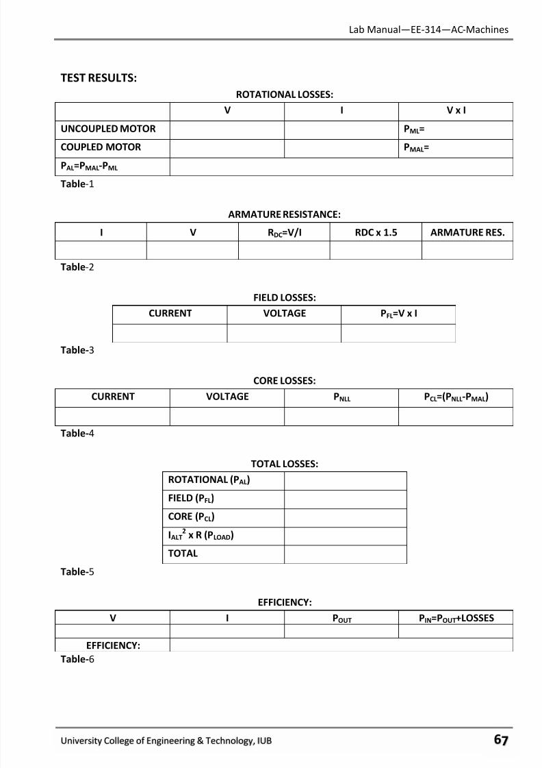
7/27/2019 AC Electric Machines Lab manul
http://slidepdf.com/reader/full/ac-electric-machines-lab-manul 69/98
Lab Manual—EE-314—AC-Machines
University College of Engineering & Technology, IUB ϊϋ
TEST RESULTS:
ROTATIONAL LOSSES:
V I V x I
UNCOUPLED MOTOR PML
=
COUPLED MOTOR PMAL=
PAL=PMAL-PML
Table-1
ARMATURE RESISTANCE:
I V RDC=V/I RDC x 1.5 ARMATURE RES.
Table-2
FIELD LOSSES:
CURRENT VOLTAGE PFL=V x I
Table-3
CORE LOSSES:
CURRENT VOLTAGE PNLL PCL=(PNLL-PMAL)
Table-4
TOTAL LOSSES:
ROTATIONAL (PAL)
FIELD (PFL)
CORE (PCL)
IALT
2
x R (PLOAD)TOTAL
Table-5
EFFICIENCY:
V I POUT PIN=POUT+LOSSES
EFFICIENCY:
Table-6
7/27/2019 AC Electric Machines Lab manul
http://slidepdf.com/reader/full/ac-electric-machines-lab-manul 70/98
Lab Manual—EE-314—AC-Machines
University College of Engineering & Technology, IUB ϊό
CALCULATIONS:
1. From the current recorded in Step 29 and the armature resistance computed in Part B, compute
the full load armature loss Record this value in TABLE-5.
2. Add the rotational, field, core, and armature losses and record the value in TABLE-5.
3. Compute the power output from the equation:
= E x I x 1.73 Record in TABLE-6.
4. Add the losses computed in #2 to the power output computed in #3. Record the value in TABLE-6.
5. Compute the alternator’s efficiency from the equation:
Efficiency = Power Out x100
Power Out + Losses
Record your answer in TABLE-6.
REVIEW QUESTIONS:
1. Of the following types of losses, which one varies with load:
a. core loss
b. Copper loss in armature
c. Field loss
2. Of the following types of losses, which one is a mechanical loss:
a. Rotational loss
b. Copper loss in armature
c. Field loss
3. At low loads, the efficiency of an alternator is:
a. Greater than at rated load.
b. Less than at rated load.
c. The same as rated load.
4. Most of the electrical power delivered to the load is supplied to the alternator as:
a. Electrical energy to the field.
b. Electrical energy to the armature.
c. Mechanical energy in the form of torque on the rotor shaft.
7/27/2019 AC Electric Machines Lab manul
http://slidepdf.com/reader/full/ac-electric-machines-lab-manul 71/98
Lab Manual—EE-314—AC-Machines
University College of Engineering & Technology, IUB ϊύ
5. The sum of electrical power supplied to the load and alternator losses equals:
a. The total power lost in the motor generator set.
b. The power input to the alternator.
c. The power supplied to the prime mover.
FINAL CHECKLIST:
1. Clean your equipment/materials and work benches before you leave.
2. Return all equipment and materials to their proper storage area.
3. Submit your answers to the questions, together with your data, calculations, and results
before the next laboratory session.
____________
Signature:
Lab Instructor
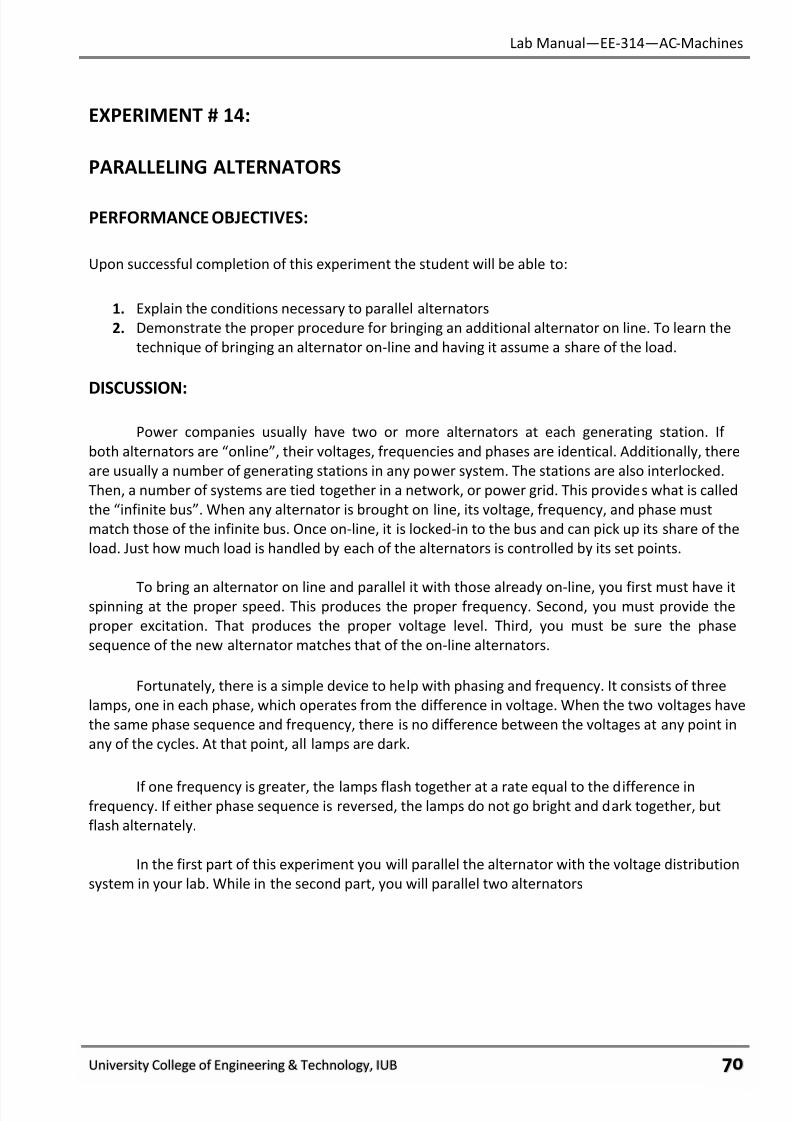
7/27/2019 AC Electric Machines Lab manul
http://slidepdf.com/reader/full/ac-electric-machines-lab-manul 72/98
Lab Manual—EE-314—AC-Machines
University College of Engineering & Technology, IUB ϋτ
EXPERIMENT # 14:
PARALLELING ALTERNATORS
PERFORMANCE OBJECTIVES:
Upon successful completion of this experiment the student will be able to:
1. Explain the conditions necessary to parallel alternators
2. Demonstrate the proper procedure for bringing an additional alternator on line. To learn the
technique of bringing an alternator on-line and having it assume a share of the load.
DISCUSSION:
Power companies usually have two or more alternators at each generating station. If
both alternators are “online”, their voltages, frequencies and phases are identical. Additionally, there
are usually a number of generating stations in any power system. The stations are also interlocked.
Then, a number of systems are tied together in a network, or power grid. This provides what is called
the “infinite bus”. When any alternator is brought on line, its voltage, frequency, and phase must
match those of the infinite bus. Once on-line, it is locked-in to the bus and can pick up its share of the
load. Just how much load is handled by each of the alternators is controlled by its set points.
To bring an alternator on line and parallel it with those already on-line, you first must have itspinning at the proper speed. This produces the proper frequency. Second, you must provide the
proper excitation. That produces the proper voltage level. Third, you must be sure the phase
sequence of the new alternator matches that of the on-line alternators.
Fortunately, there is a simple device to help with phasing and frequency. It consists of three
lamps, one in each phase, which operates from the difference in voltage. When the two voltages have
the same phase sequence and frequency, there is no difference between the voltages at any point in
any of the cycles. At that point, all lamps are dark.
If one frequency is greater, the lamps flash together at a rate equal to the difference infrequency. If either phase sequence is reversed, the lamps do not go bright and dark together, but
flash alternately.
In the first part of this experiment you will parallel the alternator with the voltage distribution
system in your lab. While in the second part, you will parallel two alternators
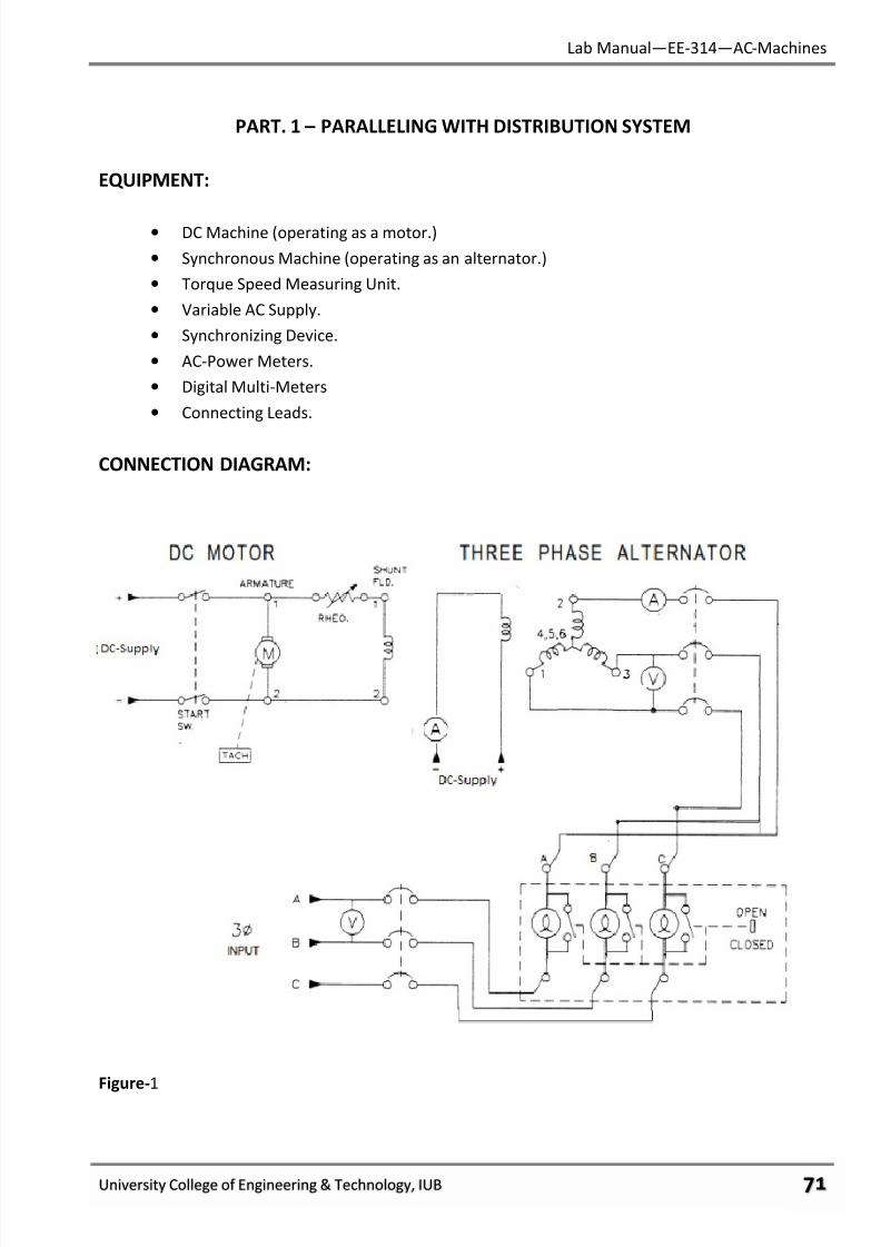
7/27/2019 AC Electric Machines Lab manul
http://slidepdf.com/reader/full/ac-electric-machines-lab-manul 73/98
Lab Manual—EE-314—AC-Machines
University College of Engineering & Technology, IUB ϋυ
PART. 1 – PARALLELING WITH DISTRIBUTION SYSTEM
EQUIPMENT:
• DC Machine (operating as a motor.)
• Synchronous Machine (operating as an alternator.)
• Torque Speed Measuring Unit.
• Variable AC Supply.
• Synchronizing Device.
• AC-Power Meters.
• Digital Multi-Meters
• Connecting Leads.
CONNECTION DIAGRAM:
Figure-1
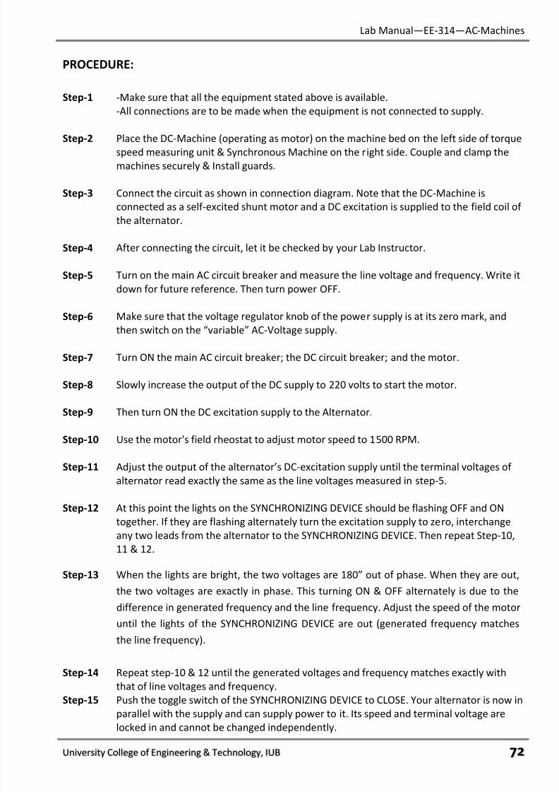
7/27/2019 AC Electric Machines Lab manul
http://slidepdf.com/reader/full/ac-electric-machines-lab-manul 74/98
Lab Manual—EE-314—AC-Machines
University College of Engineering & Technology, IUB ϋφ
PROCEDURE:
Step-1 -Make sure that all the equipment stated above is available.
-All connections are to be made when the equipment is not connected to supply.
Step-2 Place the DC-Machine (operating as motor) on the machine bed on the left side of torquespeed measuring unit & Synchronous Machine on the right side. Couple and clamp the
machines securely & Install guards.
Step-3 Connect the circuit as shown in connection diagram. Note that the DC-Machine is
connected as a self-excited shunt motor and a DC excitation is supplied to the field coil of
the alternator.
Step-4 After connecting the circuit, let it be checked by your Lab Instructor.
Step-5 Turn on the main AC circuit breaker and measure the line voltage and frequency. Write itdown for future reference. Then turn power OFF.
Step-6 Make sure that the voltage regulator knob of the power supply is at its zero mark, and
then switch on the “variable” AC-Voltage supply.
Step-7 Turn ON the main AC circuit breaker; the DC circuit breaker; and the motor.
Step-8 Slowly increase the output of the DC supply to 220 volts to start the motor.
Step-9 Then turn ON the DC excitation supply to the Alternator.
Step-10 Use the motor's field rheostat to adjust motor speed to 1500 RPM.
Step-11 Adjust the output of the alternator’s DC-excitation supply until the terminal voltages of
alternator read exactly the same as the line voltages measured in step-5.
Step-12 At this point the lights on the SYNCHRONIZING DEVICE should be flashing OFF and ON
together. If they are flashing alternately turn the excitation supply to zero, interchange
any two leads from the alternator to the SYNCHRONIZING DEVICE. Then repeat Step-10,
11 & 12.
Step-13 When the lights are bright, the two voltages are 180” out of phase. When they are out,
the two voltages are exactly in phase. This turning ON & OFF alternately is due to the
difference in generated frequency and the line frequency. Adjust the speed of the motor
until the lights of the SYNCHRONIZING DEVICE are out (generated frequency matches
the line frequency).
Step-14 Repeat step-10 & 12 until the generated voltages and frequency matches exactly with
that of line voltages and frequency.
Step-15 Push the toggle switch of the SYNCHRONIZING DEVICE to CLOSE. Your alternator is now in
parallel with the supply and can supply power to it. Its speed and terminal voltage are
locked in and cannot be changed independently.
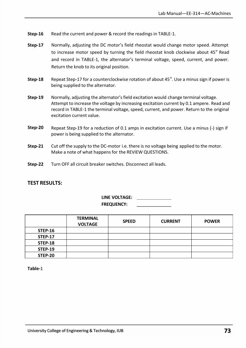
7/27/2019 AC Electric Machines Lab manul
http://slidepdf.com/reader/full/ac-electric-machines-lab-manul 75/98
Lab Manual—EE-314—AC-Machines
University College of Engineering & Technology, IUB ϋχ
Step-16 Read the current and power & record the readings in TABLE-1.
Step-17 Normally, adjusting the DC motor’s field rheostat would change motor speed. Attempt
to increase motor speed by turning the field rheostat knob clockwise about 45o
Read
and record in TABLE-1, the alternator’s terminal voltage, speed, current, and power.Return the knob to its original position.
Step-18 Repeat Step-17 for a counterclockwise rotation of about 45o. Use a minus sign if power is
being supplied to the alternator.
Step-19 Normally, adjusting the alternator’s field excitation would change terminal voltage.
Attempt to increase the voltage by increasing excitation current by 0.1 ampere. Read and
record in TABLE-1 the terminal voltage, speed, current, and power. Return to the original
excitation current value.
Step-20 Repeat Step-19 for a reduction of 0.1 amps in excitation current. Use a minus (-) sign if
power is being supplied to the alternator.
Step-21 Cut off the supply to the DC-motor i.e. there is no voltage being applied to the motor.
Make a note of what happens for the REVIEW QUESTIONS.
Step-22 Turn OFF all circuit breaker switches. Disconnect all leads.
TEST RESULTS:
LINE VOLTAGE: ______________
FREQUENCY: ______________
TERMINAL
VOLTAGESPEED CURRENT POWER
STEP-16
STEP-17
STEP-18STEP-19
STEP-20
Table-1
7/27/2019 AC Electric Machines Lab manul
http://slidepdf.com/reader/full/ac-electric-machines-lab-manul 76/98
Lab Manual—EE-314—AC-Machines
University College of Engineering & Technology, IUB ϋψ
PART. 2 – PARALLELING TWO ALTERNATORS
EQUIPMENT:
• 2-DC Machines (operating as motors.)
• 2-Synchronous Machines (operating as alternators.)
• Torque Speed Measuring Unit.
• Variable AC Supply.
• Synchronizing Device.
• AC-Power Meters.
• Digital Multi-Meters.
• Resistive Load.
• Inductive Load.
• Connecting Leads.
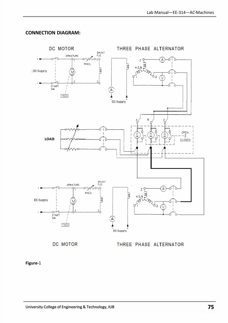
7/27/2019 AC Electric Machines Lab manul
http://slidepdf.com/reader/full/ac-electric-machines-lab-manul 77/98
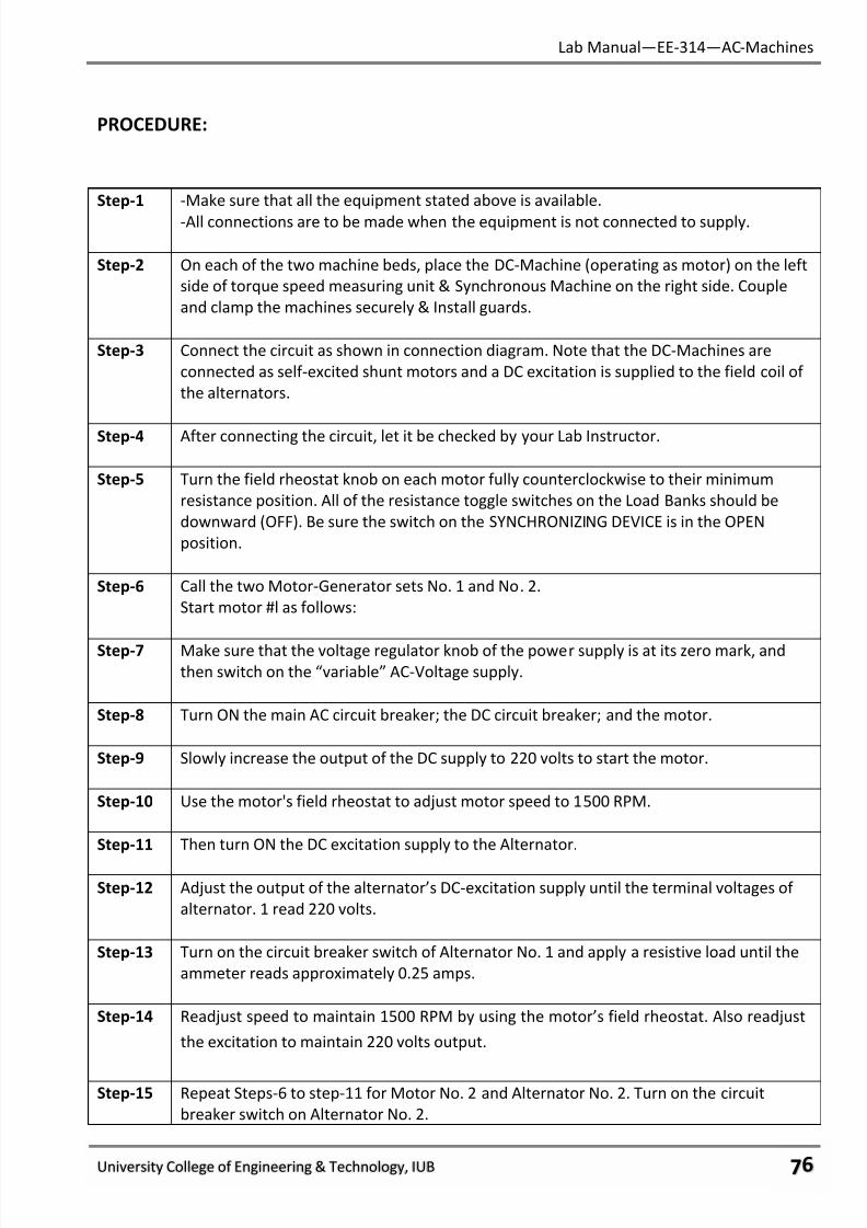
7/27/2019 AC Electric Machines Lab manul
http://slidepdf.com/reader/full/ac-electric-machines-lab-manul 78/98
Lab Manual—EE-314—AC-Machines
University College of Engineering & Technology, IUB ϋϊ
PROCEDURE:
Step-1 -Make sure that all the equipment stated above is available.
-All connections are to be made when the equipment is not connected to supply.
Step-2 On each of the two machine beds, place the DC-Machine (operating as motor) on the left
side of torque speed measuring unit & Synchronous Machine on the right side. Couple
and clamp the machines securely & Install guards.
Step-3 Connect the circuit as shown in connection diagram. Note that the DC-Machines are
connected as self-excited shunt motors and a DC excitation is supplied to the field coil of
the alternators.
Step-4 After connecting the circuit, let it be checked by your Lab Instructor.
Step-5 Turn the field rheostat knob on each motor fully counterclockwise to their minimum
resistance position. All of the resistance toggle switches on the Load Banks should be
downward (OFF). Be sure the switch on the SYNCHRONIZING DEVICE is in the OPEN
position.
Step-6 Call the two Motor-Generator sets No. 1 and No. 2.
Start motor #l as follows:
Step-7 Make sure that the voltage regulator knob of the power supply is at its zero mark, andthen switch on the “variable” AC-Voltage supply.
Step-8 Turn ON the main AC circuit breaker; the DC circuit breaker; and the motor.
Step-9 Slowly increase the output of the DC supply to 220 volts to start the motor.
Step-10 Use the motor's field rheostat to adjust motor speed to 1500 RPM.
Step-11 Then turn ON the DC excitation supply to the Alternator.
Step-12 Adjust the output of the alternator’s DC-excitation supply until the terminal voltages of
alternator. 1 read 220 volts.
Step-13 Turn on the circuit breaker switch of Alternator No. 1 and apply a resistive load until the
ammeter reads approximately 0.25 amps.
Step-14 Readjust speed to maintain 1500 RPM by using the motor’s field rheostat. Also readjust
the excitation to maintain 220 volts output.
Step-15 Repeat Steps-6 to step-11 for Motor No. 2 and Alternator No. 2. Turn on the circuit
breaker switch on Alternator No. 2.
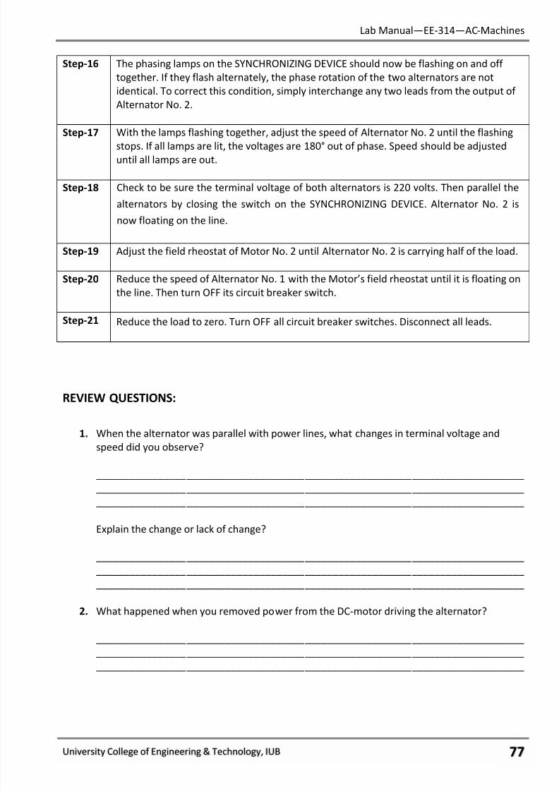
7/27/2019 AC Electric Machines Lab manul
http://slidepdf.com/reader/full/ac-electric-machines-lab-manul 79/98
Lab Manual—EE-314—AC-Machines
University College of Engineering & Technology, IUB ϋϋ
Step-16 The phasing lamps on the SYNCHRONIZING DEVICE should now be flashing on and off
together. If they flash alternately, the phase rotation of the two alternators are not
identical. To correct this condition, simply interchange any two leads from the output of
Alternator No. 2.
Step-17 With the lamps flashing together, adjust the speed of Alternator No. 2 until the flashing
stops. If all lamps are lit, the voltages are 180° out of phase. Speed should be adjusted
until all lamps are out.
Step-18 Check to be sure the terminal voltage of both alternators is 220 volts. Then parallel the
alternators by closing the switch on the SYNCHRONIZING DEVICE. Alternator No. 2 is
now floating on the line.
Step-19 Adjust the field rheostat of Motor No. 2 until Alternator No. 2 is carrying half of the load.
Step-20 Reduce the speed of Alternator No. 1 with the Motor’s field rheostat until it is floating onthe line. Then turn OFF its circuit breaker switch.
Step-21 Reduce the load to zero. Turn OFF all circuit breaker switches. Disconnect all leads.
REVIEW QUESTIONS:
1. When the alternator was parallel with power lines, what changes in terminal voltage and
speed did you observe?
____________________________________________________________________________
____________________________________________________________________________
____________________________________________________________________________
Explain the change or lack of change?
____________________________________________________________________________ ____________________________________________________________________________
____________________________________________________________________________
2. What happened when you removed power from the DC-motor driving the alternator?
____________________________________________________________________________
____________________________________________________________________________
____________________________________________________________________________

7/27/2019 AC Electric Machines Lab manul
http://slidepdf.com/reader/full/ac-electric-machines-lab-manul 80/98
Lab Manual—EE-314—AC-Machines
University College of Engineering & Technology, IUB ϋό
3. Explain how you were able to cause the paralleled alternators to pick-up a greater share of
load?
____________________________________________________________________________
____________________________________________________________________________
____________________________________________________________________________
4. What four conditions must match in order to bring an alternator on line?
a. ________________________________________________________________________
b. ________________________________________________________________________ c. ________________________________________________________________________
d. ________________________________________________________________________
5. When an alternator is “floating on the line, it is:
a. Supplying a portion of the load current.
b. Receiving AC power from the lines.
c. Neither supplying nor receiving AC power.
6. The speed of prime mover determines:
a. Frequency
b. Phase rotationc. Phase relationship with bus
7. The field excitation of the alternator determines:
a. Frequency
b. Voltage
c. Phase Rotation
8. The synchronizing (phasing) lamps operate from the difference between two voltages. When
they remain dark:
a. Voltages are equal and 180’out of phase.
b. Voltages are equal and in-phase.
c. Voltages are unequal and out of phase.
9. When an alternator is paralleled with the infinite bus, you cannot change:
a. The load current it supplies.
b. The power it supplies.
c. The frequency of its output.

7/27/2019 AC Electric Machines Lab manul
http://slidepdf.com/reader/full/ac-electric-machines-lab-manul 81/98
Lab Manual—EE-314—AC-Machines
University College of Engineering & Technology, IUB ϋύ
FINAL CHECKLIST:
1. Clean your equipment/materials and work benches before you leave.
2. Return all equipment and materials to their proper storage area.
3. Submit your answers to the questions, together with your data, calculations, and results
before the next laboratory session.
____________Signature:
Lab Instructor
7/27/2019 AC Electric Machines Lab manul
http://slidepdf.com/reader/full/ac-electric-machines-lab-manul 82/98
Lab Manual—EE-314—AC-Machines
University College of Engineering & Technology, IUB ότ
EXPERIMENT # 15:
STARTING AND SYNCHRONIZING SYNCHRONOUS MACHINES
PERFORMANCE OBJECTIVES:
Upon successful completion of this experiment the student will be able to:
1. Explain the principle of synchronous motors.
2. Start and synchronize a synchronous motor.
DISCUSSION:
When three-phase is applied to the stator of a three-phase motor, a revolving stator
magnetic field is created. This field revolves at synchronous speed, which is a speed determined by
the number of poles per phase of the motor and the frequency of the incoming power. The rotor of
a synchronous motor becomes “locked in” on the revolving stator field. It then rotates at
synchronous speed. To accomplish this, the rotor contains a DC field winding.
The problem is in starting. If you have DC applied to the field coil, while the rotor is standing
still, the revolving field passes the stationary field much too fast to be locked onto. First the DC field
coils on the rotor must be made to rotate almost as fast as the revolving stator field. Then, when
you apply DC to it, the rotor is pulled into synchronism. That means that the rotor turns at
synchronous speed.
To get the rotor turning in the first place, a squirrel-cage winding is used. The bars are
embedded in the rotor core. When power is applied to the stator, the revolving field induces voltage
into these windings. In other words, a synchronous motor starts as an induction motor. When the
rotor reaches 95% of synchronous speed, DC is switched into the rotor field winding.
Now, during the start process, there will also be voltage induced into the DC field winding as
the rotor turns. Rather than have a charged-up field coil, its terminals are shorted through a resistor
while the squirrel-cage winding is getting the rotor started. Because synchronous motors must
achieve 95% synchronous speed before being synchronized, they are rarely started under load. Load
is applied after it is running as a synchronous motor. The rotor, however, continues to turn at
synchronous speed.
It is possible to load a synchronous motor beyond its ability to stay in synchronism. The
counter-torque of a load overcomes the torque (pull) on the rotor from the revolving stator field.
When that happens, the motor pulls out of step with the stator field. It will not simply fall back to
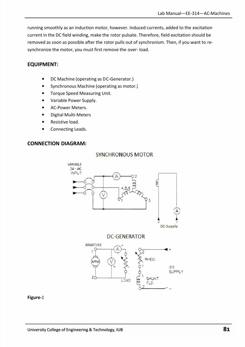
7/27/2019 AC Electric Machines Lab manul
http://slidepdf.com/reader/full/ac-electric-machines-lab-manul 83/98
Lab Manual—EE-314—AC-Machines
University College of Engineering & Technology, IUB όυ
running smoothly as an induction motor, however. Induced currents, added to the excitation
current in the DC field winding, make the rotor pulsate. Therefore, field excitation should be
removed as soon as possible after the rotor pulls out of synchronism. Then, if you want to re-
synchronize the motor, you must first remove the over- load.
EQUIPMENT:
• DC Machine (operating as DC-Generator.)
• Synchronous Machine (operating as motor.)
• Torque Speed Measuring Unit.
• Variable Power Supply.
• AC-Power Meters.
• Digital Multi-Meters
• Resistive load.
• Connecting Leads.
CONNECTION DIAGRAM:
Figure-1
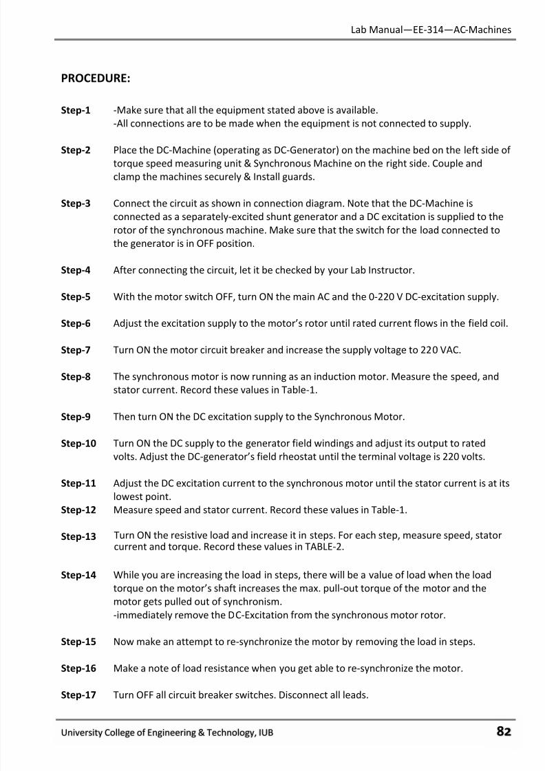
7/27/2019 AC Electric Machines Lab manul
http://slidepdf.com/reader/full/ac-electric-machines-lab-manul 84/98
Lab Manual—EE-314—AC-Machines
University College of Engineering & Technology, IUB όφ
PROCEDURE:
Step-1 -Make sure that all the equipment stated above is available.
-All connections are to be made when the equipment is not connected to supply.
Step-2 Place the DC-Machine (operating as DC-Generator) on the machine bed on the left side of
torque speed measuring unit & Synchronous Machine on the right side. Couple and
clamp the machines securely & Install guards.
Step-3 Connect the circuit as shown in connection diagram. Note that the DC-Machine is
connected as a separately-excited shunt generator and a DC excitation is supplied to the
rotor of the synchronous machine. Make sure that the switch for the load connected to
the generator is in OFF position.
Step-4 After connecting the circuit, let it be checked by your Lab Instructor.
Step-5 With the motor switch OFF, turn ON the main AC and the 0-220 V DC-excitation supply.
Step-6 Adjust the excitation supply to the motor’s rotor until rated current flows in the field coil.
Step-7 Turn ON the motor circuit breaker and increase the supply voltage to 220 VAC.
Step-8 The synchronous motor is now running as an induction motor. Measure the speed, and
stator current. Record these values in Table-1.
Step-9 Then turn ON the DC excitation supply to the Synchronous Motor.
Step-10 Turn ON the DC supply to the generator field windings and adjust its output to rated
volts. Adjust the DC-generator’s field rheostat until the terminal voltage is 220 volts.
Step-11 Adjust the DC excitation current to the synchronous motor until the stator current is at its
lowest point.
Step-12 Measure speed and stator current. Record these values in Table-1.
Step-13 Turn ON the resistive load and increase it in steps. For each step, measure speed, statorcurrent and torque. Record these values in TABLE-2.
Step-14 While you are increasing the load in steps, there will be a value of load when the load
torque on the motor’s shaft increases the max. pull-out torque of the motor and the
motor gets pulled out of synchronism.
-immediately remove the DC-Excitation from the synchronous motor rotor.
Step-15 Now make an attempt to re-synchronize the motor by removing the load in steps.
Step-16 Make a note of load resistance when you get able to re-synchronize the motor.
Step-17 Turn OFF all circuit breaker switches. Disconnect all leads.
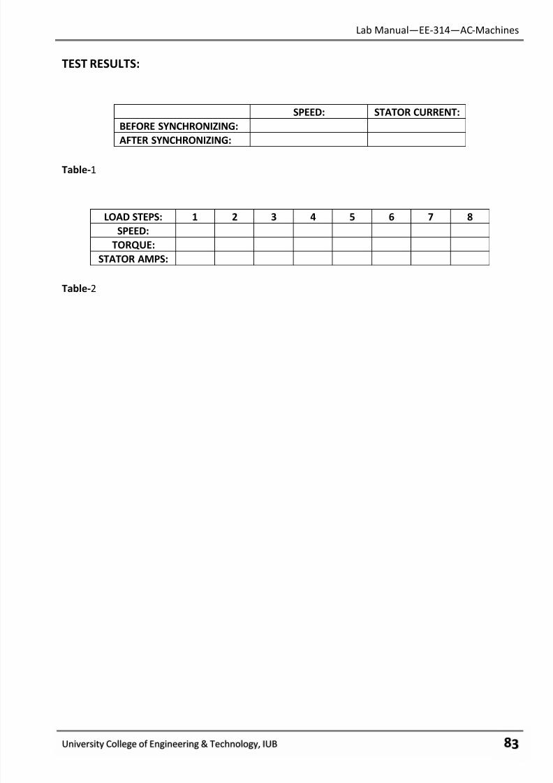
7/27/2019 AC Electric Machines Lab manul
http://slidepdf.com/reader/full/ac-electric-machines-lab-manul 85/98
Lab Manual—EE-314—AC-Machines
University College of Engineering & Technology, IUB όχ
TEST RESULTS:
SPEED: STATOR CURRENT:
BEFORE SYNCHRONIZING:
AFTER SYNCHRONIZING:
Table-1
LOAD STEPS: 1 2 3 4 5 6 7 8
SPEED:
TORQUE:
STATOR AMPS:
Table-2

7/27/2019 AC Electric Machines Lab manul
http://slidepdf.com/reader/full/ac-electric-machines-lab-manul 86/98
Lab Manual—EE-314—AC-Machines
University College of Engineering & Technology, IUB όψ
REVIEW QUESTIONS:
1. The damper winding (squirrel-cage) starts the rotor and gets it up to 95% synchronous speed.
After DC is applied to the rotor field coil and the rotor pulls up to synchronous speed, what is
the job of the damper winding? Explain.
____________________________________________________________________________
____________________________________________________________________________
____________________________________________________________________________
2. Why isn’t DC applied to the rotor field coil right away instead of waiting until the rotor is up to
speed?
____________________________________________________________________________
____________________________________________________________________________
____________________________________________________________________________
3. What happened to rotor speed as you synchronized the rotor?
____________________________________________________________________________
____________________________________________________________________________
____________________________________________________________________________
What happened to stator current?
____________________________________________________________________________Explain why rotor speed changed the way it did.
____________________________________________________________________________
4. What was the “pull-out torque” for this motor? (Pull-out torque is the maximum torque the
motor will produce before dropping out of synchronism).
____________________________________________________________________________
5. When a synchronous motor is loaded, its speed:
a. Increases.
b. Decreases.
c. Remains the same.
6. Normally, the stator current of a synchronous motor is:
a. Higher than that of an induction motor.
b. Lower than that of an induction motor.
c. The same as that of an induction motor.
7/27/2019 AC Electric Machines Lab manul
http://slidepdf.com/reader/full/ac-electric-machines-lab-manul 87/98
Lab Manual—EE-314—AC-Machines
University College of Engineering & Technology, IUB όω
7. A synchronous motor will not “synchronize” if:
a. The stator has a revolving field.
b. The load on the rotor is too great.
c. DC is applied to the field coil on the rotor.
8. As the motor was loaded, stator current:
a. Increased.
b. Decreased.
c. Remains the same.
9. You can easily tell when a synchronous motor drops out of synchronism, because the rotor
begins to:
a. Speed up.b. Pulsate.
c. Reverse direction.
FINAL CHECKLIST:
1. Clean your equipment/materials and work benches before you leave.
2. Return all equipment and materials to their proper storage area.
3. Submit your answers to the questions, together with your data, calculations, and resultsbefore the next laboratory session.
____________
Signature:
Lab Instructor
7/27/2019 AC Electric Machines Lab manul
http://slidepdf.com/reader/full/ac-electric-machines-lab-manul 88/98
Lab Manual—EE-314—AC-Machines
University College of Engineering & Technology, IUB όϊ
EXPERIMENT # 16:
SYNCHRONOUS MOTOR V-CURVES
PERFORMANCE OBJECTIVES:
Upon successful completion of this experiment the student will be able to:
1. Demonstrate change in synchronous motor power factor.
2. Explain the effect of excitation current in terms of V-curves.
DISCUSSION:
Synchronous motors have the unique ability to run at different power factors.
Motors actually require electric power for two reasons. The first is to supply power current
that gets converted to mechanical power for the load and rotational losses. The second kind of
electrical input to a motor is the excitation current. Excitation current stores energy in the magnetic
field and releases it back to the source. Excitation current, which does no actual work, is ninety
degrees out of phase with power current.
Induction motors must draw both the power current and the excitation current from the AC
lines. That’s ’why typical induction motors operate with 0.8 lagging power factor.
Synchronous motors, on the other hand, have a separate source of excitation current. If you
wanted to supply less than normal excitation current to the DC field coil on the rotor, a synchronous
motor would run at 0.8 lagging power factor, the same as induction motors. This is seldom done,
however.
Instead the excitation current is increased to point where it magnetizes the rotor, stator, and
air gap so that no excitation current is taken from the AC lines at all. The entire stator current,
therefore, is converted to mechanical power. The synchronous motor has a unity power factor.
Excitation current can, however, be increased above normal. Now, not only does the motor
not take any excitation current from the AC lines, it actually supplied excitation current to the AC
lines. Typical synchronous motors can run at 0.8 P.F., leading.
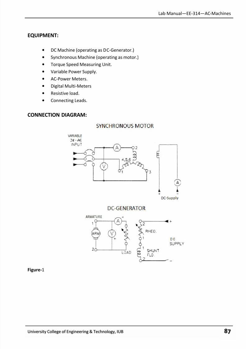
7/27/2019 AC Electric Machines Lab manul
http://slidepdf.com/reader/full/ac-electric-machines-lab-manul 89/98
7/27/2019 AC Electric Machines Lab manul
http://slidepdf.com/reader/full/ac-electric-machines-lab-manul 90/98
Lab Manual—EE-314—AC-Machines
University College of Engineering & Technology, IUB όό
PROCEDURE:
Step-1 -Make sure that all the equipment stated above is available.
-All connections are to be made when the equipment is not connected to supply.
Step-2 Place the DC-Machine (operating as DC-Generator) on the machine bed on the left side of
torque speed measuring unit & Synchronous Machine on the right side. Couple and
clamp the machines securely & Install guards.
Step-3 Connect the circuit as shown in connection diagram. Note that the DC-Machine is
connected as a separately-excited shunt generator and a DC excitation is supplied to the
rotor of the synchronous machine. Make sure that the switch for the load connected to
the generator is in OFF position.
Step-4 After connecting the circuit, let it be checked by your Lab Instructor.
Step-5 With the motor switch OFF, turn ON the main AC and the 0-220 V DC-excitation supply.
Step-6 Adjust the excitation supply to the motor’s rotor until rated current flows in the field coil.
Then, turn OFF the supply to the motor’s field.
Step-7 Turn ON the motor circuit breaker and increase the supply voltage to 220 VAC. The
synchronous motor is now running as an induction motor.
Step-8 Then turn ON the DC excitation supply to the Synchronous Motor. The motor should nowbe synchronized with the stator’s revolving field.
Step-9 With rated amperes flowing in the DC field, record stator current in TABLE-1.
Step-10 Reduce the value of rotor current by 0.1 amps. Read and record stator current in TABLE-l.
Step-11 Continue to repeat Step 10 until the motor pulls out of synchronism and for each step,
record stator current in TABLE-l.
-When the motor pulls out of synchronism, immediately remove the DC-Excitation from
the rotor.
Step-12 Turn ON the 220 volt DC supply to the field coil of the DC-Machine.
Step-13 Adjust the field rheostat of DC-Machine until its terminal voltage is 220 volts.
Step-14 Turn ON load to the DC-Generator and vary the load resistor value until 0.5 A current
flows through the load.
Step-15 Repeat step 13.
Step-16 Repeat Steps 9, 10, 11, 12, and 13 for TABLE-2.
Step-17 Turn OFF all circuit breaker switches. Disconnect all leads.
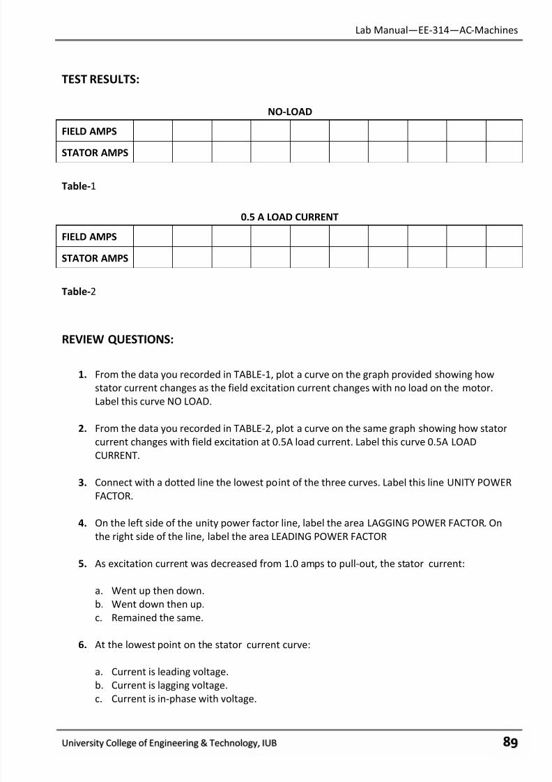
7/27/2019 AC Electric Machines Lab manul
http://slidepdf.com/reader/full/ac-electric-machines-lab-manul 91/98
Lab Manual—EE-314—AC-Machines
University College of Engineering & Technology, IUB όύ
TEST RESULTS:
NO-LOAD
FIELD AMPS
STATOR AMPS
Table-1
0.5 A LOAD CURRENT
FIELD AMPS
STATOR AMPS
Table-2
REVIEW QUESTIONS:
1. From the data you recorded in TABLE-1, plot a curve on the graph provided showing how
stator current changes as the field excitation current changes with no load on the motor.
Label this curve NO LOAD.
2. From the data you recorded in TABLE-2, plot a curve on the same graph showing how stator
current changes with field excitation at 0.5A load current. Label this curve 0.5A LOAD
CURRENT.
3. Connect with a dotted line the lowest point of the three curves. Label this line UNITY POWER
FACTOR.
4. On the left side of the unity power factor line, label the area LAGGING POWER FACTOR. On
the right side of the line, label the area LEADING POWER FACTOR
5. As excitation current was decreased from 1.0 amps to pull-out, the stator current:
a. Went up then down.
b. Went down then up.
c. Remained the same.
6. At the lowest point on the stator current curve:
a. Current is leading voltage.
b. Current is lagging voltage.c. Current is in-phase with voltage.

7/27/2019 AC Electric Machines Lab manul
http://slidepdf.com/reader/full/ac-electric-machines-lab-manul 92/98
Lab Manual—EE-314—AC-Machines
University College of Engineering & Technology, IUB ύτ
7. Normal excitation is when the synchronous motor has:
a. Unity power factor.
b. Leading power factor.
c. Lagging power factor.
8. Under-excitation produces a:
a. Unity power factor.
b. Leading power factor.
c. Lagging power factor.
9. Over-excitation produces a:
a. Unity power factor.
b. Leading power factor.
c. Lagging power factor.
GRAPH:
FINAL CHECKLIST:
1. Clean your equipment/materials and work benches before you leave.
2. Return all equipment and materials to their proper storage area.
3. Submit your answers to the questions, together with your data, calculations, and results
before the next laboratory session.
____________
Signature:
Lab Instructor
7/27/2019 AC Electric Machines Lab manul
http://slidepdf.com/reader/full/ac-electric-machines-lab-manul 93/98
Lab Manual—EE-314—AC-Machines
University College of Engineering & Technology, IUB ύυ
EXPERIMENT # 17:
POWER FACTOR CORRECTION USING SYNCHRONOUS MOTORS.
PERFORMANCE OBJECTIVES:
Upon successful completion of this experiment the student will be able to:
1. Explain how synchronous motors improve power factor.
2. Connect a synchronous motor in a way that improves system power factor.
DISCUSSION:
Power factor, quite simply, is the ratio of power current to the total current.
An induction motor operates at less than unity power factor because it draws both power
current and excitation voltage from the AC power line. Factories that have a lot of induction motors
in use may have a low, lagging power factor.
Three main detrimental effects of a low, lagging power factor are:
1. Low power factor cuts down system loadability. That is, it reduces the capacity of the power
system to carry kilowatts. The capacity of all apparatus is determined by the KVA it can carry.
Hence, larger generators, transmission lines, transformers, feeders and switches must be
provided for each kilowatt of load when power factor is low than when it is high. Thus, capitalinvestment per kilowatt of load is higher.
2. Low power factor means more current per kilowatt. Hence, each kilowatt must carry a higher
burden of line losses, making it cost more to transport each kilowatt of power.
3. Low power factor may depress the voltage, reducing the output of practically all electrical
apparatus.
At low, lagging power factor also affects the following:
1. GENERATORS: Reduces generator capacity and efficiency.
2. TRANSFORMERS: Increases the voltage drop across transformers so that voltage regulationof the transformer is impaired.
3. DISTRIBUTION LOSSES: Makes larger distribution lines necessary and causes a greater
voltage drop in these lines.
4. POWER COST: A majority of power companies have penalties in their rates for low, lagging
power factor and incentives for high power factor. The customer thus ben- efits when he
keeps the power factor of his plant high.
Power factor can be corrected with a capacitor. However, if a synchronous motor is run with
a leading power factor, it can perform useful work and correct power factor at the same time. What
this means is that the exciting current, instead of flowing back and forth from induction motor to
power company, flows back and forth between the induction and synchronous motors.
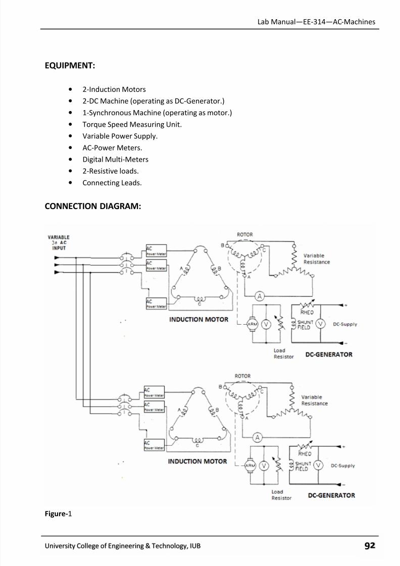
7/27/2019 AC Electric Machines Lab manul
http://slidepdf.com/reader/full/ac-electric-machines-lab-manul 94/98
Lab Manual—EE-314—AC-Machines
University College of Engineering & Technology, IUB ύφ
EQUIPMENT:
• 2-Induction Motors
• 2-DC Machine (operating as DC-Generator.)
• 1-Synchronous Machine (operating as motor.)
• Torque Speed Measuring Unit.
• Variable Power Supply.
• AC-Power Meters.
• Digital Multi-Meters
• 2-Resistive loads.
• Connecting Leads.
CONNECTION DIAGRAM:
Figure-1
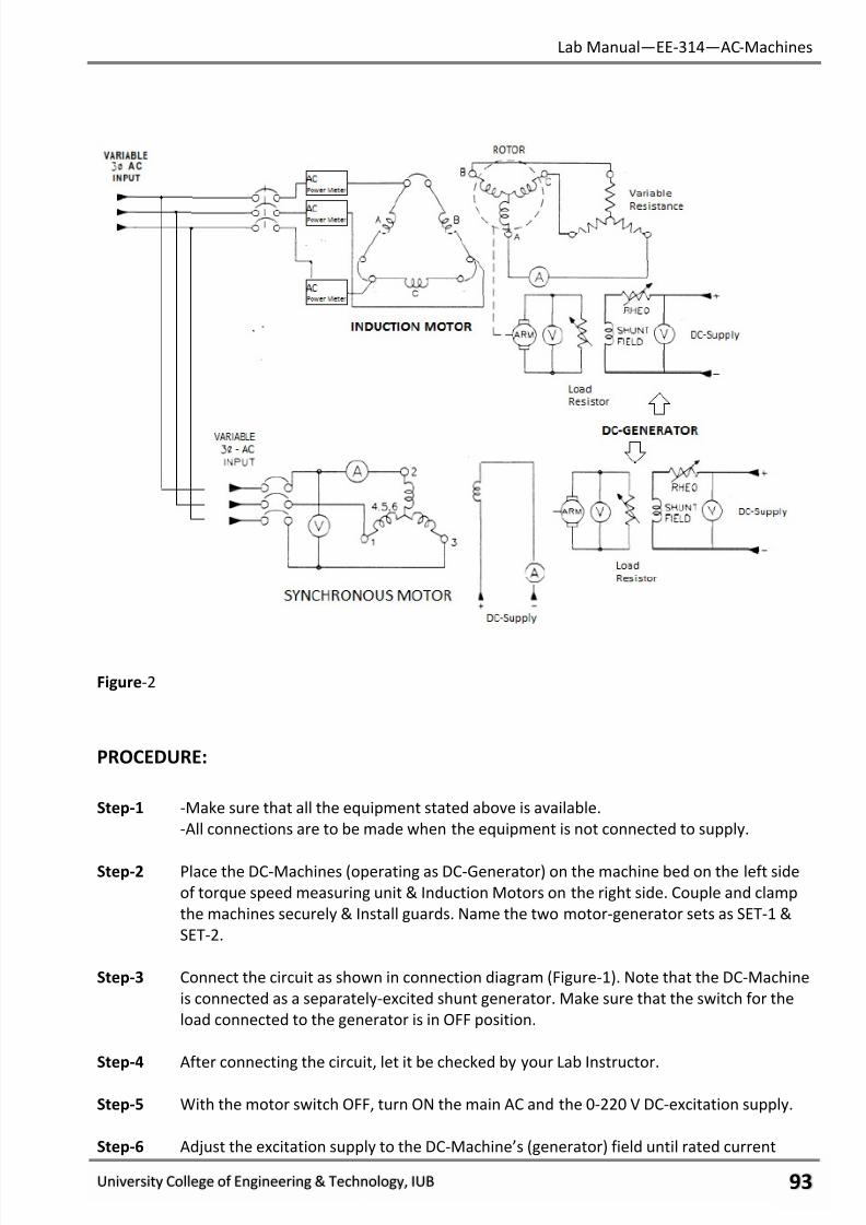
7/27/2019 AC Electric Machines Lab manul
http://slidepdf.com/reader/full/ac-electric-machines-lab-manul 95/98
Lab Manual—EE-314—AC-Machines
University College of Engineering & Technology, IUB ύχ
Figure-2
PROCEDURE:
Step-1 -Make sure that all the equipment stated above is available.
-All connections are to be made when the equipment is not connected to supply.
Step-2 Place the DC-Machines (operating as DC-Generator) on the machine bed on the left side
of torque speed measuring unit & Induction Motors on the right side. Couple and clamp
the machines securely & Install guards. Name the two motor-generator sets as SET-1 &
SET-2.
Step-3 Connect the circuit as shown in connection diagram (Figure-1). Note that the DC-Machine
is connected as a separately-excited shunt generator. Make sure that the switch for the
load connected to the generator is in OFF position.
Step-4 After connecting the circuit, let it be checked by your Lab Instructor.
Step-5 With the motor switch OFF, turn ON the main AC and the 0-220 V DC-excitation supply.
Step-6 Adjust the excitation supply to the DC-Machine’s (generator) field until rated current
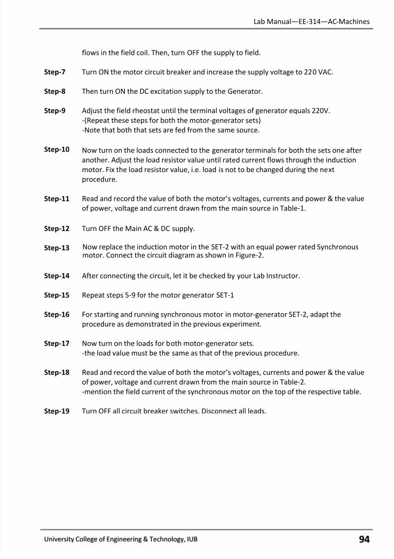
7/27/2019 AC Electric Machines Lab manul
http://slidepdf.com/reader/full/ac-electric-machines-lab-manul 96/98
Lab Manual—EE-314—AC-Machines
University College of Engineering & Technology, IUB ύψ
flows in the field coil. Then, turn OFF the supply to field.
Step-7 Turn ON the motor circuit breaker and increase the supply voltage to 220 VAC.
Step-8 Then turn ON the DC excitation supply to the Generator.
Step-9 Adjust the field rheostat until the terminal voltages of generator equals 220V.
-(Repeat these steps for both the motor-generator sets)
-Note that both that sets are fed from the same source.
Step-10 Now turn on the loads connected to the generator terminals for both the sets one after
another. Adjust the load resistor value until rated current flows through the induction
motor. Fix the load resistor value, i.e. load is not to be changed during the next
procedure.
Step-11 Read and record the value of both the motor’s voltages, currents and power & the value
of power, voltage and current drawn from the main source in Table-1.
Step-12 Turn OFF the Main AC & DC supply.
Step-13 Now replace the induction motor in the SET-2 with an equal power rated Synchronousmotor. Connect the circuit diagram as shown in Figure-2.
Step-14 After connecting the circuit, let it be checked by your Lab Instructor.
Step-15 Repeat steps 5-9 for the motor generator SET-1
Step-16 For starting and running synchronous motor in motor-generator SET-2, adapt the
procedure as demonstrated in the previous experiment.
Step-17 Now turn on the loads for both motor-generator sets.
-the load value must be the same as that of the previous procedure.
Step-18 Read and record the value of both the motor’s voltages, currents and power & the value
of power, voltage and current drawn from the main source in Table-2.
-mention the field current of the synchronous motor on the top of the respective table.
Step-19 Turn OFF all circuit breaker switches. Disconnect all leads.
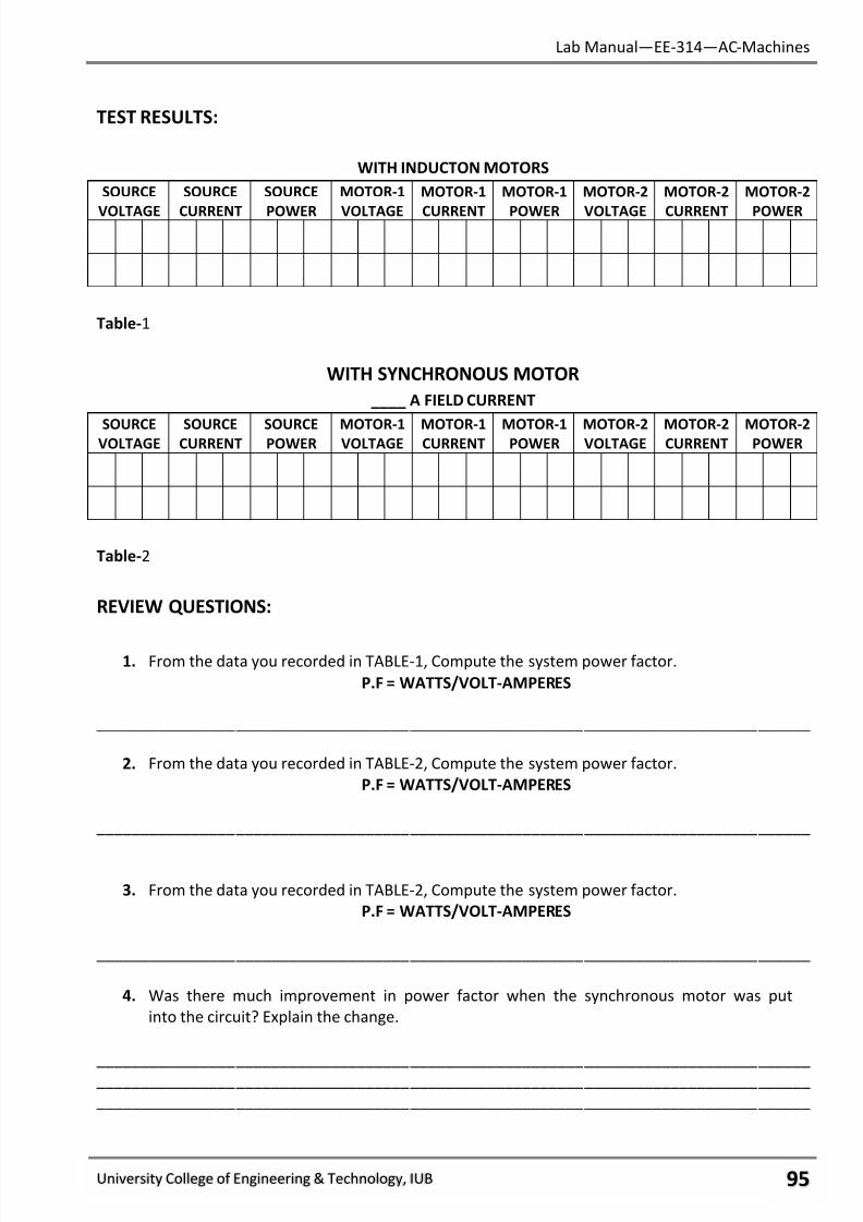
7/27/2019 AC Electric Machines Lab manul
http://slidepdf.com/reader/full/ac-electric-machines-lab-manul 97/98
Lab Manual—EE-314—AC-Machines
University College of Engineering & Technology, IUB ύω
TEST RESULTS:
WITH INDUCTON MOTORS
SOURCE
VOLTAGE
SOURCE
CURRENT
SOURCE
POWER
MOTOR-1
VOLTAGE
MOTOR-1
CURRENT
MOTOR-1
POWER
MOTOR-2
VOLTAGE
MOTOR-2
CURRENT
MOTOR-2
POWER
Table-1
WITH SYNCHRONOUS MOTOR
____ A FIELD CURRENT
SOURCEVOLTAGE
SOURCECURRENT
SOURCEPOWER
MOTOR-1VOLTAGE
MOTOR-1CURRENT
MOTOR-1POWER
MOTOR-2VOLTAGE
MOTOR-2CURRENT
MOTOR-2POWER
Table-2
REVIEW QUESTIONS:
1. From the data you recorded in TABLE-1, Compute the system power factor.
P.F = WATTS/VOLT-AMPERES
__________________________________________________________________________________
2. From the data you recorded in TABLE-2, Compute the system power factor.
P.F = WATTS/VOLT-AMPERES
__________________________________________________________________________________
3. From the data you recorded in TABLE-2, Compute the system power factor.
P.F = WATTS/VOLT-AMPERES
__________________________________________________________________________________
4. Was there much improvement in power factor when the synchronous motor was put
into the circuit? Explain the change.
__________________________________________________________________________________
__________________________________________________________________________________
__________________________________________________________________________________
7/27/2019 AC Electric Machines Lab manul
http://slidepdf.com/reader/full/ac-electric-machines-lab-manul 98/98
Lab Manual—EE-314—AC-Machines
5. Induction motors typically have:
a. A high leading power factor.
b. A low leading power factor.
c. c) A low lagging power factor.
6. Excitation current furnishes:
a. Total apparent power.
b. Real (true) active power.
c. Reactive (wattless) power.
7. When the excitation current for an induction motor comes from the AC lines:
a. Excitation current makes up a large share of the total current.
b. Excitation current makes up a small share of the total current.
c. None of the total current is made up of excitation current.
8. When some of the excitation current for an induction motor comes from a synchro- nous
motor:
a. Excitation current makes up a large share of the total current.
b. Excitation current makes up a small share of the total current.
c. None of the total current is made up of excitation current.
9. Synchronous motors usually run at:
a. Unity or lagging power factor.
b. Unity or leading power factor.
c. Lagging or leading power factor.