Embed Size (px)
Citation preview
PRIMERGY
PRIMERGY TX300 S3Server Options GuideSusanne DäschleinFujitsu Siemens Computers GmbH München81730 Münchene-mail: email: [email protected].: (089) 61001155Fax: (++49) 700 / 372 00000TX300 S3Sprachen: En
Edition July 2006

Comments… Suggestions… Corrections…The User Documentation Department would like toknow your opinion of this manual. Your feedback helpsus optimize our documentation to suit your individual needs.
Fax forms for sending us your comments are included inthe back of the manual.
There you will also find the addresses of the relevantUser Documentation Department.
Certified documentation according to DIN EN ISO 9001:2000To ensure a consistently high quality standard anduser-friendliness, this documentation was created tomeet the regulations of a quality management system which complies with the requirements of the standardDIN EN ISO 9001:2000.
cognitas. Gesellschaft für Technik-Dokumentation mbHwww.cognitas.de
Copyright and TrademarksCopyright © 2006 Fujitsu Siemens Computers GmbH.
All rights reserved.Delivery subject to availability; right of technical modifications reserved.
All hardware and software names used are trademarks of their respective manufacturers.
TX300 S3 Options Guide
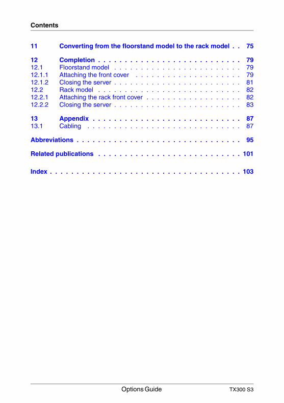
Contents1 Introduction . . . . . . . . . . . . . . . . . . . . . . . . . . . 51.1 Overview of the documentation . . . . . . . . . . . . . . . . . . 51.2 Extensions and conversions . . . . . . . . . . . . . . . . . . . . 61.3 Notational conventions . . . . . . . . . . . . . . . . . . . . . . 8
2 Procedure . . . . . . . . . . . . . . . . . . . . . . . . . . . . 9
3 Safety notes . . . . . . . . . . . . . . . . . . . . . . . . . . 11
4 Preparation . . . . . . . . . . . . . . . . . . . . . . . . . . . 174.1 Floorstand model . . . . . . . . . . . . . . . . . . . . . . . . 174.1.1 Opening the server . . . . . . . . . . . . . . . . . . . . . . . 174.1.2 Removing the front cover . . . . . . . . . . . . . . . . . . . . 184.2 Rack model . . . . . . . . . . . . . . . . . . . . . . . . . . . 204.2.1 Opening the server . . . . . . . . . . . . . . . . . . . . . . . 204.2.2 Removing the rack front cover . . . . . . . . . . . . . . . . . . 23
5 Main memory . . . . . . . . . . . . . . . . . . . . . . . . . . 255.1 Equipping rules . . . . . . . . . . . . . . . . . . . . . . . . . 255.2 Extending/replacing the main memory . . . . . . . . . . . . . 27
6 Processors . . . . . . . . . . . . . . . . . . . . . . . . . . . 316.1 Installing a second processor . . . . . . . . . . . . . . . . . . 316.2 Replacing the processor . . . . . . . . . . . . . . . . . . . . 406.3 Replacing the heat sink . . . . . . . . . . . . . . . . . . . . . 42
7 ROMB (RAID on motherboard) . . . . . . . . . . . . . . . . 457.1 Installing the ROMB upgrade kit . . . . . . . . . . . . . . . . . 45
8 Accessible drives . . . . . . . . . . . . . . . . . . . . . . . 478.1 Installing an accessible 5.25-inch drive . . . . . . . . . . . . . 478.2 Installing a slimline CD/DVD drive . . . . . . . . . . . . . . . . 528.3 Installing a slimline floppy disk drive . . . . . . . . . . . . . . 568.4 Installing a LocalView module . . . . . . . . . . . . . . . . . . 598.5 Installing the FDD-DVD-LocalView box . . . . . . . . . . . . . 618.6 Installing the SAS/SATA HDD extension box . . . . . . . . . . 62
9 Controller in non-hot-plug PCI slots . . . . . . . . . . . . . 679.1 Installing a controller . . . . . . . . . . . . . . . . . . . . . . 68
10 Parallel interface for printers . . . . . . . . . . . . . . . . . 7110.1 Installing a parallel interface . . . . . . . . . . . . . . . . . . . 71
Options Guide TX300 S3
Contents
11 Converting from the floorstand model to the rack model . . 75
12 Completion . . . . . . . . . . . . . . . . . . . . . . . . . . . 7912.1 Floorstand model . . . . . . . . . . . . . . . . . . . . . . . . 7912.1.1 Attaching the front cover . . . . . . . . . . . . . . . . . . . . 7912.1.2 Closing the server . . . . . . . . . . . . . . . . . . . . . . . . 8112.2 Rack model . . . . . . . . . . . . . . . . . . . . . . . . . . . 8212.2.1 Attaching the rack front cover . . . . . . . . . . . . . . . . . . 8212.2.2 Closing the server . . . . . . . . . . . . . . . . . . . . . . . . 83
13 Appendix . . . . . . . . . . . . . . . . . . . . . . . . . . . . 8713.1 Cabling . . . . . . . . . . . . . . . . . . . . . . . . . . . . . 87
Abbreviations . . . . . . . . . . . . . . . . . . . . . . . . . . . . . . . 95
Related publications . . . . . . . . . . . . . . . . . . . . . . . . . . . 101
Index . . . . . . . . . . . . . . . . . . . . . . . . . . . . . . . . . . . . 103
TX300 S3 Options Guide 5
Introduction Overview of the documentation
1 IntroductionThe PRIMERGY TX300 S3 Server is an Intel-based server for medium-sized and large networks. The server is suitable for use as a file server as well as an application, information, or Internet server. It is available as a floorstand or rack model. The floorstand model can be converted to a rack model using an optional conversion kit.
1.1 Overview of the documentation
I PRIMERGY manuals are available in PDF format on the ServerBooks CD which is supplied in the ServerView Suite package for every server system.
These PDF files can also be downloaded free of charge from the Internet: at http://manuals.fujitsu-siemens.com you will find an overview page with the online documentation available on the Internet. You can go to the PRIMERGY Server documentation by clicking on industry standard servers.
Concept and target groups
This Options Guide shows you how you can expand and upgrade the server.
I The Operating Manual for the server describes how you install/remove the hot-plug components.
The activities described in this manual may only be performed by technical specialists.
Additional documentation about the server
The PRIMERGY TX300 S3 documentation comprises the following additional manuals:
– The “Safety notes and other important information” manual (printed copy always supplied with the server, and available as a PDF file on the ServerBooks CD supplied)
– The “Guarantee” manual (printed copy always supplied with the server, and available as a PDF file on the ServerBooks CD supplied)
– The “Returning used devices” manual (PDF file available on the ServerBooks CD)
6 Options Guide TX300 S3
Extensions and conversions Introduction
– The Operating Manual for PRIMERGY TX300 S3 (PDF available on the ServerBooks CD supplied)
– The Technical Manual for the system board D2129(PDF available on the ServerBooks CD supplied)
– The “BIOS Setup” manual (PDF available on the ServerBooks CD supplied)– The “PRIMERGY ServerView Suite - ServerStart” manual (printed copy
always supplied with the server, and available as PDF file on the ServerBooks CD supplied)
– The “Global Array Manager Client Software User’s Guide” (PDF available on the ServerBooks CD supplied)
– The “Global Array Manager Server Software User’s Guide” (PDF available on the ServerBooks CD supplied)
– The “Integrated Mirroring User’s Guide” (PDF available on the ServerBooks CD supplied)
I You can order a supplementary ServerBooks CD by sending an e-mail to the following address, quoting your server data: [email protected]
Further sources of information:
– Technical Manual on the relevant rack– Manual on the monitor– Manual on ServerView Server Management– Manual on RemoteView Remote Server Maintenance– Manual on LocalView– Documentation on boards and drives– Documentation on your operating system– Information files on your operating system
(see also “Related publications” on page 101)
1.2 Extensions and conversions
Second processor
The system board can be upgraded with a second processor. Only processors of the same type may be used on the system board. The second processor must have at least the same clock frequency as the first processor.
TX300 S3 Options Guide 7
Introduction Extensions and conversions
Extension of the main memory
The eight slots for the main memory are suitable for FBD533/PC2-4200F or FBD667/PC2-5300F Fully Buffered DIMM memory modules. The organization in four memory banks, 1 to 4, permits rapid memory access with two-way inter-leaving.
Memory modules must always be incorporated in pairs. A memory bank must always be equipped fully with the same type of memory modules.
ROMB (RAID on motherboard)
The on-board SAS RAID controller can be upgraded to a RAID5 (RAID 0, 1, 5, 10, 50) controller with a "MegaRaid ROMB SAS" upgrade kit. In this case the the RAID5 funtionality is activated by installing a license key and a cache module.
RemoteView
RemoteView provides you with a comprehensive test and diagnostics package. The relevant hardware components are integrated on the system board.
Additional accessible drives
Three free 5.25-inch bays are available for accessible drives.
In the third 5.25-inch bay a DVD-ROM drive or a multibay (FDD-DVD-LocalView box) can be installed. The multibay can be equipped with a slimline floppy disk drive, a slimline DVD-ROM drive and a LocalView module.
In the second and the third 5.25-inch bay a SAS/SATA HDD extension box can be installed. This SAS/SATA HDD extension box can be equipped with a slimline floppy disk drive (or a LocalView module), a slimline DVD-ROM drive and two SAS/SATA hard disks.
LocalView module (alphanumeric system display)
The LocalView module provides you with the option of displaying system infor-mation and hardware system faults alphanumerically. This is an intelligent module with a micro controller and its own memory, which functions indepen-dently of the server system.
8 Options Guide TX300 S3
Notational conventions Introduction
The LocalView module consists of an LCD display panel and a toggle switch, both accommodated in a suitable mount. The mechanical mechanism used allows the LCD display panel to be pulled out and flapped out. Further infor-mation on operating the display modes are provided in the documentation on the LocalView module.
Additional controllers in non-hot-plug PCI slots
The system board offers five PCI slots. Slots 1, 2 and 5 are non-hot-plug PCI slots.
PCI slots 3 and 4 are hot-plug PCI slots which can be equipped with controllers that have hot-plug capability (the hot-plug PCI slots are described in the Operating Manual).
Parallel interface for printers
As an option, a parallel interface can be provided for printers.
Conversion of the floorstand model to a rack model
The floorstand model can optionally be converted so that the server can be integrated into the common rack systems.
1.3 Notational conventions
The following notational conventions are used in this manual:
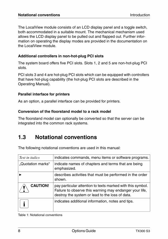
Text in italics indicates commands, menu items or software programs.
„Quotation marks“ indicate names of chapters and terms that are being emphasized.
Ê describes activities that must be performed in the order shown.
V CAUTION! pay particular attention to texts marked with this symbol. Failure to observe this warning may endanger your life, destroy the system or lead to the loss of data.
I indicates additional information, notes and tips.
Table 1: Notational conventions
TX300 S3 Options Guide 9
2 ProcedureV CAUTION!
The actions described in these instructions should only be performed by technical specialists. Equipment repairs should only be performed by authorized, qualified staff. Any unauthorized opening and improper repairs could expose the user to risks (electric shock, energy hazards, fire hazards) and could also damage the equipment. Please note that any unauthorized opening of the device will result in the invalidation of the warranty and exclusion from all liability.
Ê First of all please familiarize yourself with the safety instructions in the section chapter “Safety notes” on page 11ff.
Ê Ensure that all required manuals (see “Additional documentation about the server” on page 5) are available, printing out the PDF files if necessary. You will definitely need the Operating Manual for the server and the Technical Manual for the system board.
Ê Shut down the server correctly, switch it off, pull out the power plug, and open the server as described in the chapter “Preparation” on page 17ff.
Ê Extend or upgrade your server as described in the relevant chapter.
I The Operating Manual for the server describes how you install/remove the hot-plug components.
I Procedures which are identical for the floorstand and rack models are only described for the floorstand model.
Ê Close the server, connect it to the power outlet, and switch it on as described in the chapter “Completion” on page 79ff.
Ê Start the operating system and, if necessary, configure it as required (see the Operating Manual).

TX300 S3 Options Guide 11
3 Safety notesI The following safety notes are also provided in the “Safety notes and
other important information” manual.
This device complies with the relevant safety regulations for data processing equipment.
If you have any questions about where you can set up the device, contact your sales outlet or our customer service team.
V CAUTION!
The actions described in these instructions should only be performed by technicians, service personnel or technical specialists. Equipment repairs should only be performed by authorized, qualified staff. Any unauthorized openings and improper repairs could expose the user to risks (electric shock, energy hazards, fire hazards) and could also damage the equipment. Please note that any unauthorized openings of the device will result in the invalidation of the warranty and exclusion from all liability.
Before operating the device
V CAUTION!
● During installation and before operating the device, observe the instructions on environmental conditions for your device.
● If the device is brought in from a cold environment, condensation may form both inside and on the outside of the machine.
Wait until the device has acclimatized to room temperature and is absolutely dry before starting it up. Material damage may be caused to the device if this requirement is not observed.
● Transport the device only in the original packaging or in packaging that protects it from knocks and jolts.
12 Options Guide TX300 S3
Safety notes
Installation and operation
V CAUTION!
● If the rack model is integrated in an installation that receives power from an industrial (public) power supply network with the IEC309 connector, the (public) power supply protection must comply with the requirements for the non-industrial (public) power supply networks for the type A connector.
● The server automatically sets itself to a voltage in the range of 100 V to 240 V. Make sure that your local voltage is within this range.
● This device has a specially approved power cable and must only be connected to a grounded insulated socket.
● Ensure that the power socket on the device or the grounded wall outlet is freely accessible.
● The ON/OFF button does not disconnect the device from the mains voltage. To disconnect the line voltage completely, remove all power plugs from the grounded insulated sockets.
● Always connect the device and the attached peripherals to the same power circuit. Otherwise you run the risk of losing data if, for example, the central processing unit is still running but the peripheral device (e.g. storage subsystem) has failed during a power outage.
● Data cables to peripheral devices must be adequately shielded.
● To the LAN wiring the requirements apply in accordance with the standards EN 50173 and EN 50174-1/2. As minimum requirement the use of a protected LAN line of category 5 for 10/100 MBps Ethernet, and/or of category 5e for Gigabit Ethernet is considered. The requirements of the specification ISO/IEC 11801 are to be considered.
● Route the cables in such a way that they do not form a potential hazard (make sure no-one can trip over them) and that they cannot be damaged. When connecting up a device, refer to the relevant notes in this manual.
● Never connect or disconnect data transmission lines during a storm (lightning hazard).
TX300 S3 Options Guide 13
Safety notes
V CAUTION!
● Make sure that no objects (such as bracelets or paper clips) fall into or liquids spill into the device (risk of electric shock or short circuit).
● In emergencies (e.g. damaged casing, controls or cables, penetration of liquids or foreign matter), switch off the device immediately, remove the power plug and contact your sales outlet or customer service team.
● Proper operation of the device (in accordance with IEC 60950/EN 60950) is only ensured if the casing is completely assembled and the rear covers for the installation openings have been put in place (electric shock, cooling, fire protection, interference suppression).
● Only install system expansions that satisfy the requirements and rules governing safety and electromagnetic compatibility and relating to telecommunications terminal equipment. If you install other expan-sions, you may damage the system or violate the safety regulations and regulations governing RFI suppression. Information on which system expansions are suitable can be obtained from the customer service centre or your sales outlet.
● The components or parts marked with a warning label (e.g. lightning symbol) may only be opened, removed or exchanged by authorized, qualified personnel. The hot-plug power supply units are exceptions to this rule.
● The warranty expires if the device is damaged during the installation or replacement of system expansions.
● You may only set those resolutions and refresh rates specified in the „Technical data“ section of the monitor description. Otherwise, you may damage your monitor. If you are in any doubt, contact your sales outlet or customer service centre.
14 Options Guide TX300 S3
Safety notes
Batteries
V CAUTION!
● Incorrect replacement of batteries may lead to a risk of explosion. The batteries may only be replaced with identical batteries or with a type recommended by the manufacturer (see the technical manual for the system board under “Related publications” on page 101).
● Replace the lithium battery on the system board in accordance with the instructions in the technical manual for the system board (see “Related publications” on page 101).
Notes on handling CDs and CD-/DVD-ROM drives
V CAUTION!
● Use only CDs in proper condition in the CD-/DVD-ROM drive of your server to prevent data loss, damage to the device and injuries.
● Therefore, check each CD for damage, cracks, breakage etc. before inserting it in the drive.
Please note that any additional labels applied may change the mechanical properties of a CD and cause imbalance.
Damaged and imbalanced CDs can break at high drive speeds (data loss).
Under certain conditions sharp-edged pieces of broken CDs can penetrate the cover of the drive (damage to the device) and be thrown out of the device (danger of injury, particularly on uncovered body parts such as the face or neck).
I You protect the CD-/DVD-ROM drive and prevent mechanical damage, as well as premature wearing of the CDs, by observing the following suggestions:
– Only insert the CDs in the drive when needed and remove them after use.
– Store the CDs in suitable sleeves.– Protect the CDs from exposure to heat and direct sunlight.
TX300 S3 Options Guide 15
Safety notes
Note about the laser
The CD-/DVD-ROM drive is classified for laser class 1according to IEC 60825-1.
V CAUTION!
The CD-/DVD-ROM drive contains a laser diode (LED). Sometimes the LED produces a stronger laser beam than laser class 1. Direct view into this laser beam is dangerous.
Never remove parts of the CD-/DVD-ROM drive assembly!
Modules with electrostatic-sensitive components:
Systems and components that might be damaged by electrostatic discharge (ESD) are marked with the following label:
Figure 1: ESD label
When you handle components fitted with ESDs, you must observe the following points under all circumstances:
● Remove the power plug from the power socket before inserting or removing components containing ESDs.
● You must always discharge yourself of static charges (e.g. by touching a grounded object) before working.
● The equipment and tools you use must be free of static charges.
● Only touch the components at the positions highlighted in green (touch points).
● Do not touch any exposed pins or conductors on a component.
● Use a grounding cable designed for this purpose to connect yourself to the system unit as you install components.
16 Options Guide TX300 S3
Safety notes
● Place all components on a static-safe base.
I You will find a detailed description for handling ESD components in the relevant European or international standards (DIN EN 61340-5-1, ANSI/ESD S20.20).
TX300 S3 Options Guide 17
4 PreparationV CAUTION!
Observe the safety instructions in the chapter “Safety notes” on page 11ff.
4.1 Floorstand model
4.1.1 Opening the server
Ê Terminate all applications and shut down the server correctly.
Ê If your operating system has not switched off the sever, press the on/off switch.
Ê Pull all power connectors out of the power outlets.
Ê If required, remove the lock on the side cover.
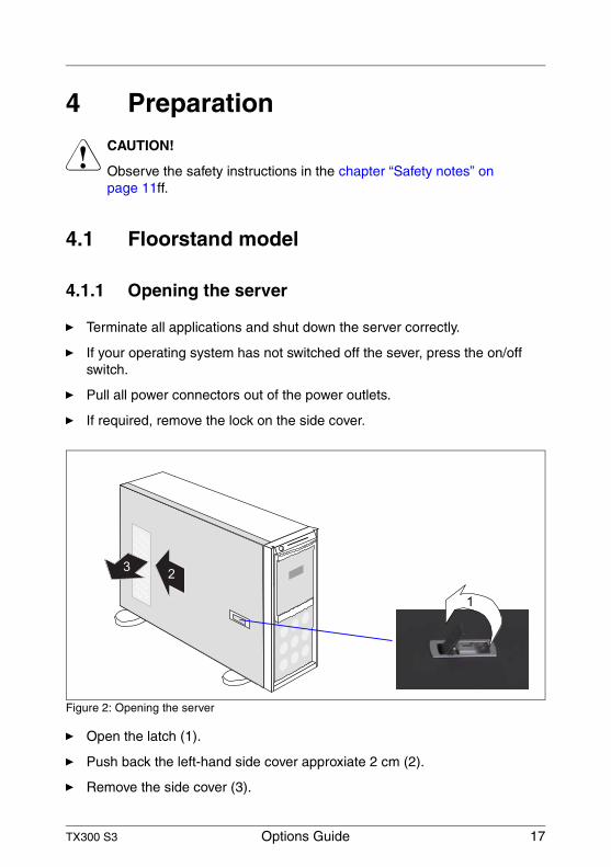
Figure 2: Opening the server
Ê Open the latch (1).
Ê Push back the left-hand side cover approxiate 2 cm (2).
Ê Remove the side cover (3).
23
1
18 Options Guide TX300 S3
Floorstand model Preparation
4.1.2 Removing the front cover
Remove the front cover when making the following extensions and upgrades:
– Installing further accessible drives
– Upgrading the floorstand model to a rack model
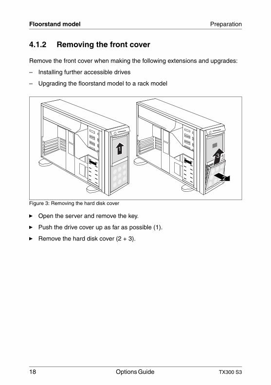
Figure 3: Removing the hard disk cover
Ê Open the server and remove the key.
Ê Push the drive cover up as far as possible (1).
Ê Remove the hard disk cover (2 + 3).
1
3
2
TX300 S3 Options Guide 19
Preparation Floorstand model
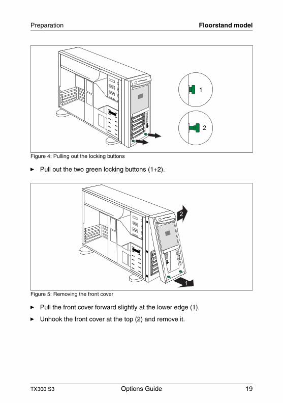
Figure 4: Pulling out the locking buttons
Ê Pull out the two green locking buttons (1+2).
Figure 5: Removing the front cover
Ê Pull the front cover forward slightly at the lower edge (1).
Ê Unhook the front cover at the top (2) and remove it.
1
2
2
1
20 Options Guide TX300 S3
Rack model Preparation
4.2 Rack model
Ê Terminate all applications and shut down the server correctly.
Ê If your operating system has not switched off the server, press the on/off button.
Ê Pull all power connectors out of the power outlets.
4.2.1 Opening the server
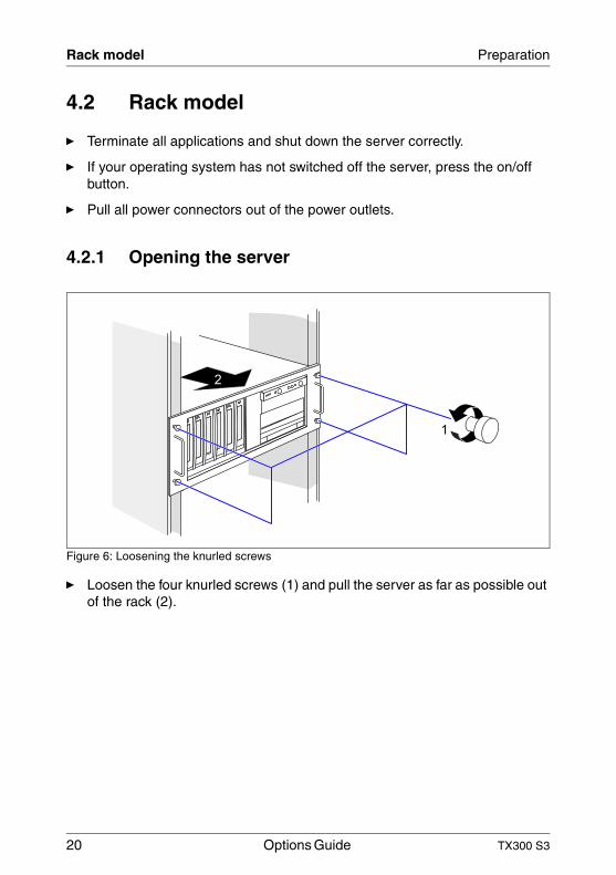
Figure 6: Loosening the knurled screws
Ê Loosen the four knurled screws (1) and pull the server as far as possible out of the rack (2).
2
1
TX300 S3 Options Guide 21
Preparation Rack model
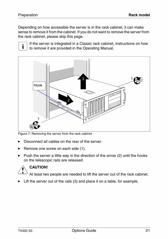
Depending on how accessible the server is in the rack cabinet, it can make sense to remove it from the cabinet. If you do not want to remove the server from the rack cabinet, please skip this page.
I If the server is integrated in a Classic rack cabinet, instructions on how to remove it are provided in the Operating Manual.
Figure 7: Removing the server from the rack cabinet
Ê Disconnect all cables on the rear of the server.
Ê Remove one screw on each side (1).
Ê Push the server a little way in the direction of the arrow (2) until the hooks on the telescopic rails are released.
V CAUTION!
At least two people are needed to lift the server out of the rack cabinet.
Ê Lift the server out of the rails (3) and place it on a table, for example.
1
1
Hook
2
3
22 Options Guide TX300 S3
Rack model Preparation
Figure 8: Opening the latch
Ê Open the latch.
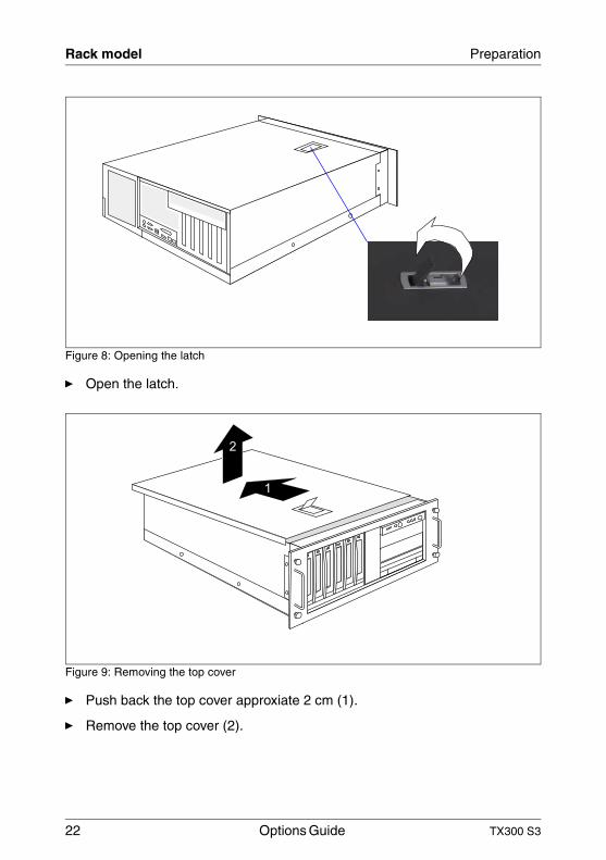
Figure 9: Removing the top cover
Ê Push back the top cover approxiate 2 cm (1).
Ê Remove the top cover (2).
1
2
TX300 S3 Options Guide 23
Preparation Rack model
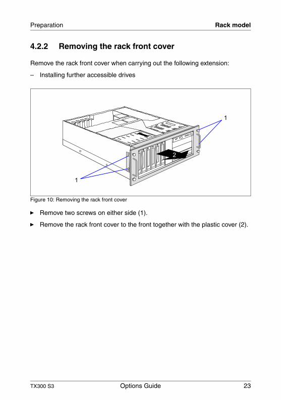
4.2.2 Removing the rack front cover
Remove the rack front cover when carrying out the following extension:
– Installing further accessible drives
Figure 10: Removing the rack front cover
Ê Remove two screws on either side (1).
Ê Remove the rack front cover to the front together with the plastic cover (2).
1
1
2

TX300 S3 Options Guide 25
5 Main memoryV CAUTION!
Observe the safety instructions in the chapter “Safety notes” on page 11ff.
The system board supports up to 32 Gbytes of main memory. 8 slots (2 slots form a memory bank) are provided for the main memory. Each memory bank is equipped with two 512-Mbyte, 1-Gbyte, 2-Gbyte or 4-Gbyte FBD533/PC2-4200F or FBD667/PC2-5300F Fully Buffered DIMM memory modules.
A memory bank can optionally be configured as a hot-spare bank.
As memory bank 1 is already equipped either with 1-Gbyte, 2-Gbyte, 4-Gbyte or 8-Gbyte of memory in the basic unit, the memory extensions can be performed up to three times for memory banks 2, 3 and 4.
ECC with memory scrubbing and with the Single Device Data Correction (SDDC, Chipkill) function is standard.
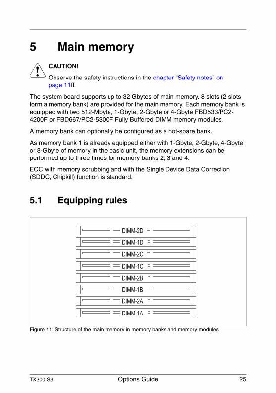
5.1 Equipping rules
Figure 11: Structure of the main memory in memory banks and memory modules
DIMM-2C
DIMM-1C
DIMM-2B
DIMM-1B
DIMM-2A
DIMM-1A
DIMM-2D
DIMM-1D
26 Options Guide TX300 S3
Equipping rules Main memory
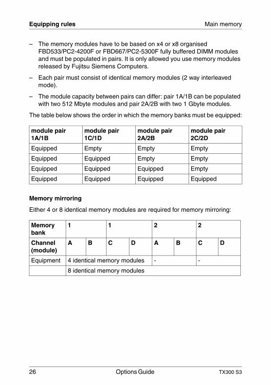
– The memory modules have to be based on x4 or x8 organised FBD533/PC2-4200F or FBD667/PC2-5300F fully buffered DIMM modules and must be populated in pairs. It is only allowed you use memory modules released by Fujitsu Siemens Computers.
– Each pair must consist of identical memory modules (2 way interleaved mode).
– The module capacity between pairs can differ: pair 1A/1B can be populated with two 512 Mbyte modules and pair 2A/2B with two 1 Gbyte modules.
The table below shows the order in which the memory banks must be equipped:
Memory mirroring
Either 4 or 8 identical memory modules are required for memory mirroring:
module pair 1A/1B
module pair 1C/1D
module pair 2A/2B
module pair 2C/2D
Equipped Empty Empty Empty
Equipped Equipped Empty Empty
Equipped Equipped Equipped Empty
Equipped Equipped Equipped Equipped
Memory bank
1 1 2 2
Channel (module)
A B C D A B C D
Equipment 4 identical memory modules - -
8 identical memory modules
TX300 S3 Options Guide 27
Main memory Extending/replacing the main memory
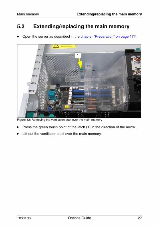
5.2 Extending/replacing the main memory
Ê Open the server as described in the chapter “Preparation” on page 17ff.
Figure 12: Removing the ventilation duct over the main memory
Ê Press the green touch point of the latch (1) in the direction of the arrow.
Ê Lift out the ventilation duct over the main memory.
1
28 Options Guide TX300 S3
Extending/replacing the main memory Main memory
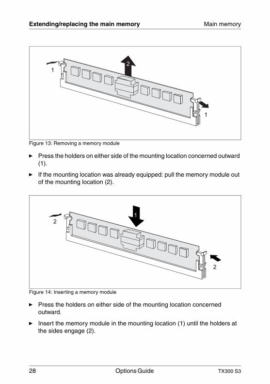
Figure 13: Removing a memory module
Ê Press the holders on either side of the mounting location concerned outward (1).
Ê If the mounting location was already equipped: pull the memory module out of the mounting location (2).
Figure 14: Inserting a memory module
Ê Press the holders on either side of the mounting location concerned outward.
Ê Insert the memory module in the mounting location (1) until the holders at the sides engage (2).
1
1
2
2
2
1
TX300 S3 Options Guide 29
Main memory Extending/replacing the main memory
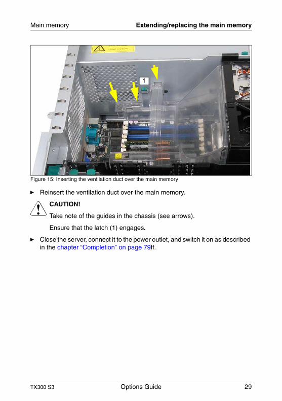
Figure 15: Inserting the ventilation duct over the main memory
Ê Reinsert the ventilation duct over the main memory.
V CAUTION!
Take note of the guides in the chassis (see arrows).
Ensure that the latch (1) engages.
Ê Close the server, connect it to the power outlet, and switch it on as described in the chapter “Completion” on page 79ff.
1

TX300 S3 Options Guide 31
6 ProcessorsV CAUTION!
Observe the safety instructions in the chapter “Safety notes” on page 11ff.
V CAUTION!
Processors are modules which can react extremely sensitively to electro-static discharges and which must therefore always be handled with care. After a processor has been removed from its protective sleeve or from its socket, place it with its smooth side down on a non-conducting, antistatic surface. Never push a processor over a surface.
6.1 Installing a second processor
The system board can be upgraded with a second processor. The upgrade kit consists of a processor, a heat sink, and a processor fan.
V CAUTION!
Only processors of the same type may be used on the system board. The second processor must have at least the same clock frequency as the first processor. The server always configures itself to the lower clock frequency of the two processors. For dual operation, use a suitable multi-processor operating system.
Ê Open the server as described in the chapter “Preparation” on page 17ff.
Ê Remove the ventilation duct over the main memory (see page 27).
32 Options Guide TX300 S3
Installing a second processor Processors
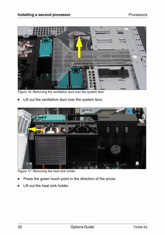
Figure 16: Removing the ventilation duct over the system fans
Ê Lift out the ventilation duct over the system fans.
Figure 17: Removing the heat sink holder
Ê Press the green touch point in the direction of the arrow.
Ê Lift out the heat sink holder.
TX300 S3 Options Guide 33
Processors Installing a second processor
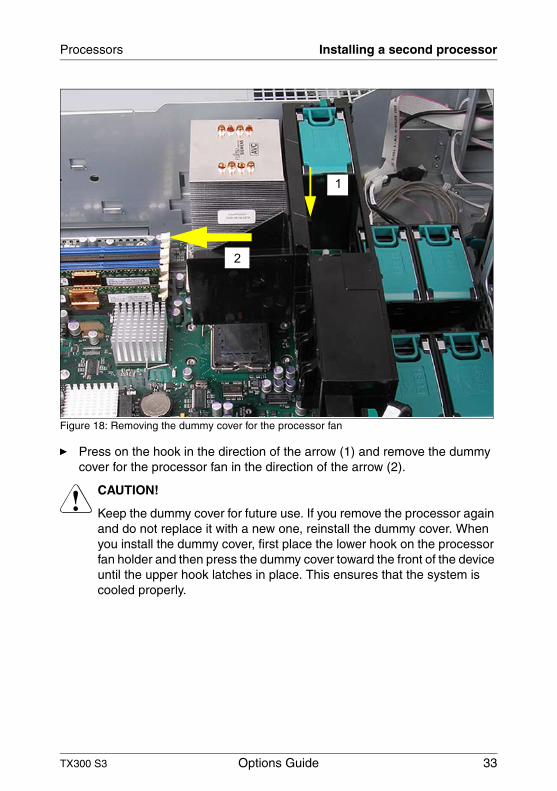
Figure 18: Removing the dummy cover for the processor fan
Ê Press on the hook in the direction of the arrow (1) and remove the dummy cover for the processor fan in the direction of the arrow (2).
V CAUTION!
Keep the dummy cover for future use. If you remove the processor again and do not replace it with a new one, reinstall the dummy cover. When you install the dummy cover, first place the lower hook on the processor fan holder and then press the dummy cover toward the front of the device until the upper hook latches in place. This ensures that the system is cooled properly.
1
2
34 Options Guide TX300 S3
Installing a second processor Processors
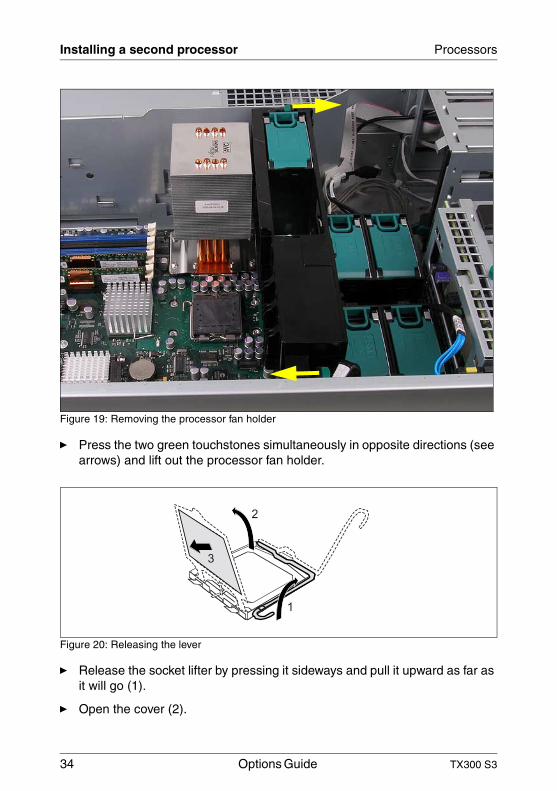
Figure 19: Removing the processor fan holder
Ê Press the two green touchstones simultaneously in opposite directions (see arrows) and lift out the processor fan holder.
Figure 20: Releasing the lever
Ê Release the socket lifter by pressing it sideways and pull it upward as far as it will go (1).
Ê Open the cover (2).
1
2
3
TX300 S3 Options Guide 35
Processors Installing a second processor
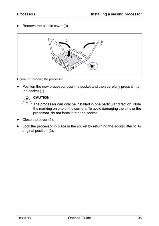
Ê Remove the plastic cover (3).
Figure 21: Inserting the processor
Ê Position the new processor over the socket and then carefully press it into the socket (1).
V CAUTION!
The processor can only be installed in one particular direction. Note the marking on one of the corners. To avoid damaging the pins or the processor, do not force it into the socket.
Ê Close the cover (2).
Ê Lock the processor in place in the socket by returning the socket lifter to its original position (3).
1
2
3
36 Options Guide TX300 S3
Installing a second processor Processors
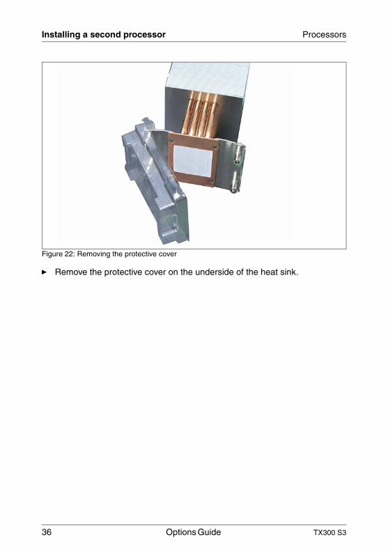
Figure 22: Removing the protective cover
Ê Remove the protective cover on the underside of the heat sink.
TX300 S3 Options Guide 37
Processors Installing a second processor
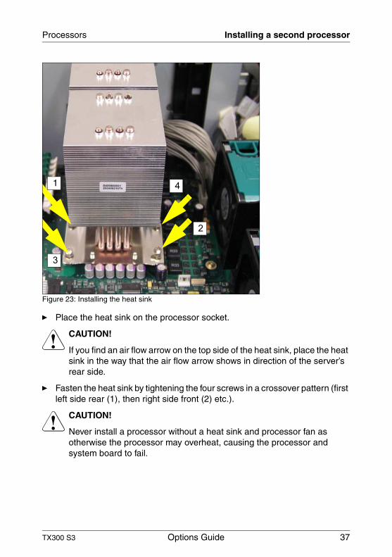
Figure 23: Installing the heat sink
Ê Place the heat sink on the processor socket.
V CAUTION!
If you find an air flow arrow on the top side of the heat sink, place the heat sink in the way that the air flow arrow shows in direction of the server’s rear side.
Ê Fasten the heat sink by tightening the four screws in a crossover pattern (first left side rear (1), then right side front (2) etc.).
V CAUTION!
Never install a processor without a heat sink and processor fan as otherwise the processor may overheat, causing the processor and system board to fail.
1 4
2
3
38 Options Guide TX300 S3
Installing a second processor Processors
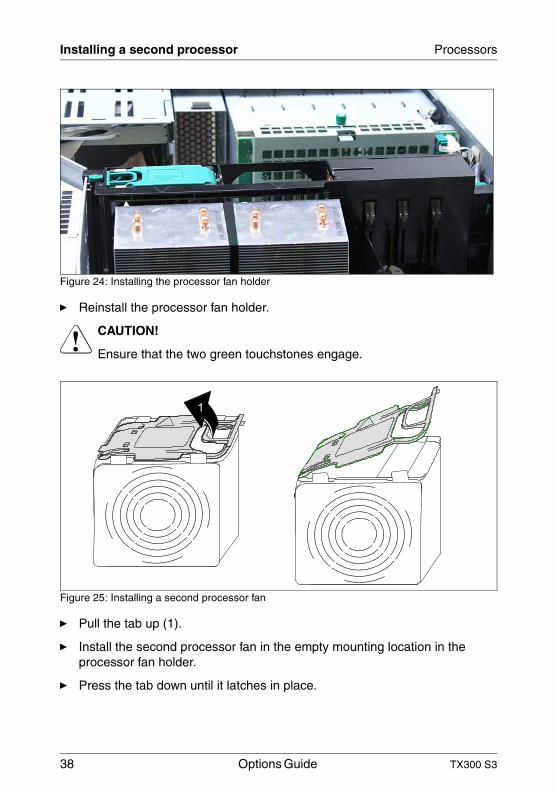
Figure 24: Installing the processor fan holder
Ê Reinstall the processor fan holder.
V CAUTION!
Ensure that the two green touchstones engage.
Figure 25: Installing a second processor fan
Ê Pull the tab up (1).
Ê Install the second processor fan in the empty mounting location in the processor fan holder.
Ê Press the tab down until it latches in place.
1
TX300 S3 Options Guide 39
Processors Installing a second processor
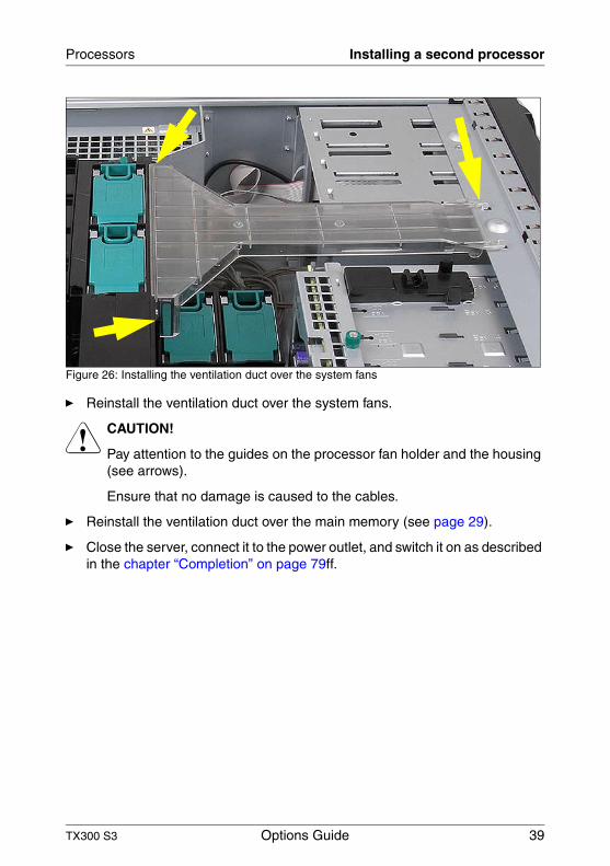
Figure 26: Installing the ventilation duct over the system fans
Ê Reinstall the ventilation duct over the system fans.
V CAUTION!
Pay attention to the guides on the processor fan holder and the housing (see arrows).
Ensure that no damage is caused to the cables.
Ê Reinstall the ventilation duct over the main memory (see page 29).
Ê Close the server, connect it to the power outlet, and switch it on as described in the chapter “Completion” on page 79ff.
40 Options Guide TX300 S3
Replacing the processor Processors
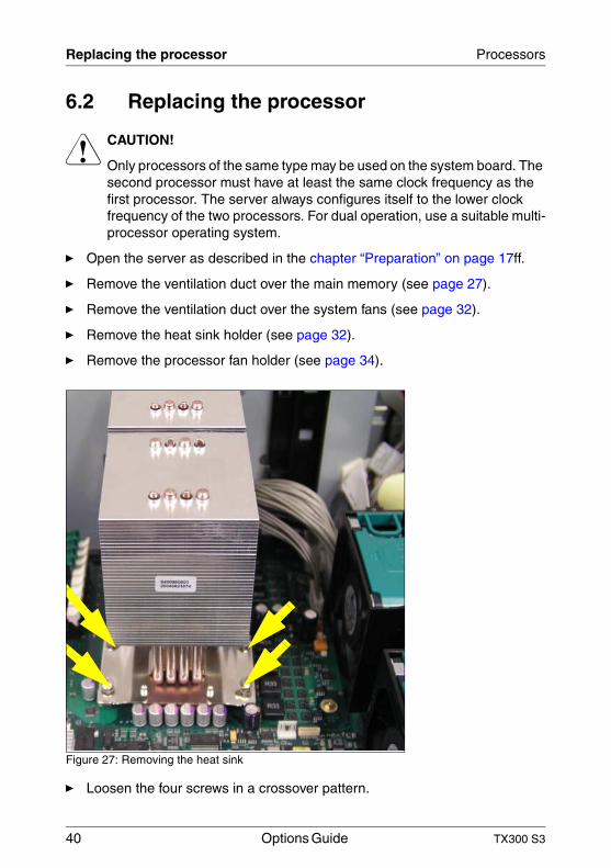
6.2 Replacing the processor
V CAUTION!
Only processors of the same type may be used on the system board. The second processor must have at least the same clock frequency as the first processor. The server always configures itself to the lower clock frequency of the two processors. For dual operation, use a suitable multi-processor operating system.
Ê Open the server as described in the chapter “Preparation” on page 17ff.
Ê Remove the ventilation duct over the main memory (see page 27).
Ê Remove the ventilation duct over the system fans (see page 32).
Ê Remove the heat sink holder (see page 32).
Ê Remove the processor fan holder (see page 34).
Figure 27: Removing the heat sink
Ê Loosen the four screws in a crossover pattern.
TX300 S3 Options Guide 41
Processors Replacing the processor
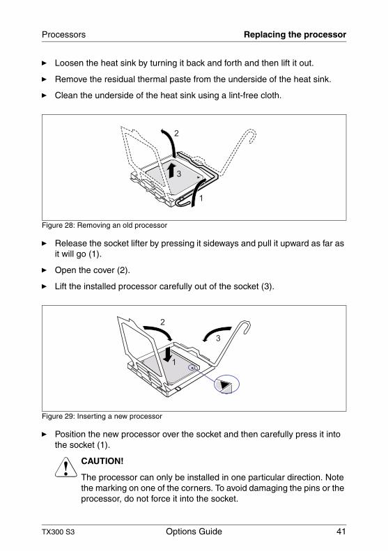
Ê Loosen the heat sink by turning it back and forth and then lift it out.
Ê Remove the residual thermal paste from the underside of the heat sink.
Ê Clean the underside of the heat sink using a lint-free cloth.
Figure 28: Removing an old processor
Ê Release the socket lifter by pressing it sideways and pull it upward as far as it will go (1).
Ê Open the cover (2).
Ê Lift the installed processor carefully out of the socket (3).
Figure 29: Inserting a new processor
Ê Position the new processor over the socket and then carefully press it into the socket (1).
V CAUTION!
The processor can only be installed in one particular direction. Note the marking on one of the corners. To avoid damaging the pins or the processor, do not force it into the socket.
1
2
3
1
2
3
42 Options Guide TX300 S3
Replacing the heat sink Processors
Ê Close the cover (2).
Ê Lock the processor in place in the socket by returning the socket lifter to its original position (3).
Ê Apply a small amount of thermal paste to the upper side of the new processor.
Ê Ensure a thin and even distribution of the thermal paste.
Ê Place the heat sink on the processor socket (see page 37).
Ê Fasten the heat sink by tightening the four screws in a crossover pattern.
Ê Reinstall the processor fan holder (see page 38).
Ê Reinstall the ventilation duct over the system fans (see page 39).
Ê Reinstall the ventilation duct over the main memory (see page 29).
Ê Close the server, connect it to the power outlet, and switch it on as described in the chapter “Completion” on page 79ff.
6.3 Replacing the heat sink
Ê Open the server as described in the chapter “Preparation” on page 17ff.
Ê Remove the ventilation duct over the main memory (see page 27).
Ê Remove the ventilation duct over the system fans (see page 32).
Ê Remove the heat sink (see page 32).
Ê Remove the processor fan holder (see page 34).
Ê Loosen the four screws on the heat sink socket in a crossover pattern (see page 40).
Ê Loosen the heat sink by turning it back and forth and then lift it out.
Ê Clean the upper side of the processor using a lint-free cloth.
Ê Remove the protective cover from the new heat sink (see page 36).
Ê Place the heat sink on the processor socket (see page 37).
Ê Fasten the heat sink by tightening the four screws in a crossover pattern.
TX300 S3 Options Guide 43
Processors Replacing the heat sink
Ê Reinstall the processor fan holder (see page 38).
Ê Reinstall the ventilation duct over the system fans (see page 39).
Ê Reinstall the ventilation duct over the main memory (see page 29).
Ê Close the server, connect it to the power outlet, and switch it on as described in the chapter “Completion” on page 79ff.

TX300 S3 Options Guide 45
7 ROMB (RAID on motherboard)V CAUTION!
Observe the safety instructions in the chapter “Safety notes” on page 11ff.
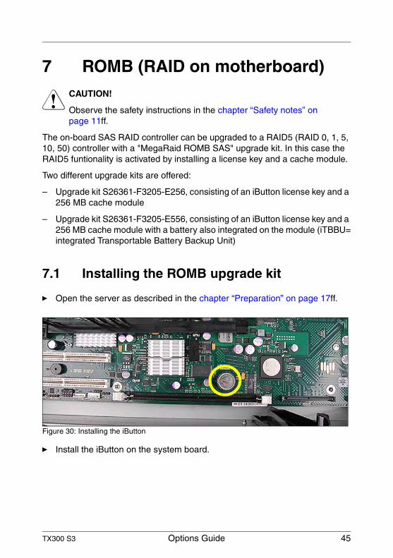
The on-board SAS RAID controller can be upgraded to a RAID5 (RAID 0, 1, 5, 10, 50) controller with a "MegaRaid ROMB SAS" upgrade kit. In this case the RAID5 funtionality is activated by installing a license key and a cache module.
Two different upgrade kits are offered:
– Upgrade kit S26361-F3205-E256, consisting of an iButton license key and a 256 MB cache module
– Upgrade kit S26361-F3205-E556, consisting of an iButton license key and a 256 MB cache module with a battery also integrated on the module (iTBBU=integrated Transportable Battery Backup Unit)
7.1 Installing the ROMB upgrade kit
Ê Open the server as described in the chapter “Preparation” on page 17ff.
Figure 30: Installing the iButton
Ê Install the iButton on the system board.
46 Options Guide TX300 S3
Installing the ROMB upgrade kit ROMB (RAID on motherboard)
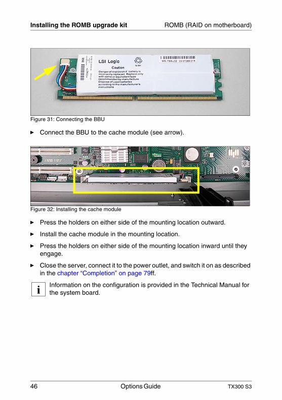
Figure 31: Connecting the BBU
Ê Connect the BBU to the cache module (see arrow).
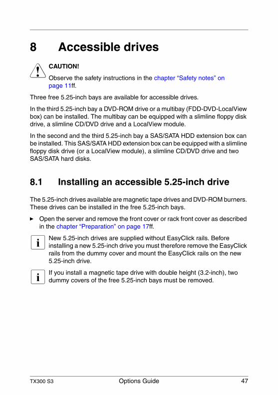
Figure 32: Installing the cache module
Ê Press the holders on either side of the mounting location outward.
Ê Install the cache module in the mounting location.
Ê Press the holders on either side of the mounting location inward until they engage.
Ê Close the server, connect it to the power outlet, and switch it on as described in the chapter “Completion” on page 79ff.
I Information on the configuration is provided in the Technical Manual for the system board.
TX300 S3 Options Guide 47
8 Accessible drivesV CAUTION!
Observe the safety instructions in the chapter “Safety notes” on page 11ff.
Three free 5.25-inch bays are available for accessible drives.
In the third 5.25-inch bay a DVD-ROM drive or a multibay (FDD-DVD-LocalView box) can be installed. The multibay can be equipped with a slimline floppy disk drive, a slimline CD/DVD drive and a LocalView module.
In the second and the third 5.25-inch bay a SAS/SATA HDD extension box can be installed. This SAS/SATA HDD extension box can be equipped with a slimline floppy disk drive (or a LocalView module), a slimline CD/DVD drive and two SAS/SATA hard disks.
8.1 Installing an accessible 5.25-inch drive
The 5.25-inch drives available are magnetic tape drives and DVD-ROM burners. These drives can be installed in the free 5.25-inch bays.
Ê Open the server and remove the front cover or rack front cover as described in the chapter “Preparation” on page 17ff.
I New 5.25-inch drives are supplied without EasyClick rails. Before installing a new 5.25-inch drive you must therefore remove the EasyClick rails from the dummy cover and mount the EasyClick rails on the new 5.25-inch drive.
I If you install a magnetic tape drive with double height (3.2-inch), two dummy covers of the free 5.25-inch bays must be removed.
48 Options Guide TX300 S3
Installing an accessible 5.25-inch drive Accessible drives
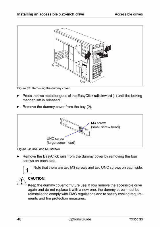
Figure 33: Removing the dummy cover
Ê Press the two metal tongues of the EasyClick rails inward (1) until the locking mechanism is released.
Ê Remove the dummy cover from the bay (2).
Figure 34: UNC and M3 screws
Ê Remove the EasyClick rails from the dummy cover by removing the four screws on each side.
I Note that there are two M3 screws and two UNC screws on each side.
V CAUTION!
Keep the dummy cover for future use. If you remove the accessible drive again and do not replace it with a new one, the dummy cover must be reinstalled to comply with EMC regulations and to satisfy cooling require-ments and fire protection measures.
1
1
2
M3 screw
(small screw head)
UNC screw
(large screw head)
TX300 S3 Options Guide 49
Accessible drives Installing an accessible 5.25-inch drive
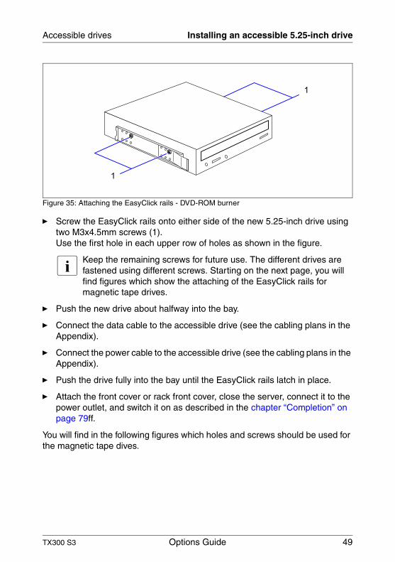
Figure 35: Attaching the EasyClick rails - DVD-ROM burner
Ê Screw the EasyClick rails onto either side of the new 5.25-inch drive using two M3x4.5mm screws (1). Use the first hole in each upper row of holes as shown in the figure.
I Keep the remaining screws for future use. The different drives are fastened using different screws. Starting on the next page, you will find figures which show the attaching of the EasyClick rails for magnetic tape drives.
Ê Push the new drive about halfway into the bay.
Ê Connect the data cable to the accessible drive (see the cabling plans in the Appendix).
Ê Connect the power cable to the accessible drive (see the cabling plans in the Appendix).
Ê Push the drive fully into the bay until the EasyClick rails latch in place.
Ê Attach the front cover or rack front cover, close the server, connect it to the power outlet, and switch it on as described in the chapter “Completion” on page 79ff.
You will find in the following figures which holes and screws should be used for the magnetic tape dives.
1
1
50 Options Guide TX300 S3
Installing an accessible 5.25-inch drive Accessible drives
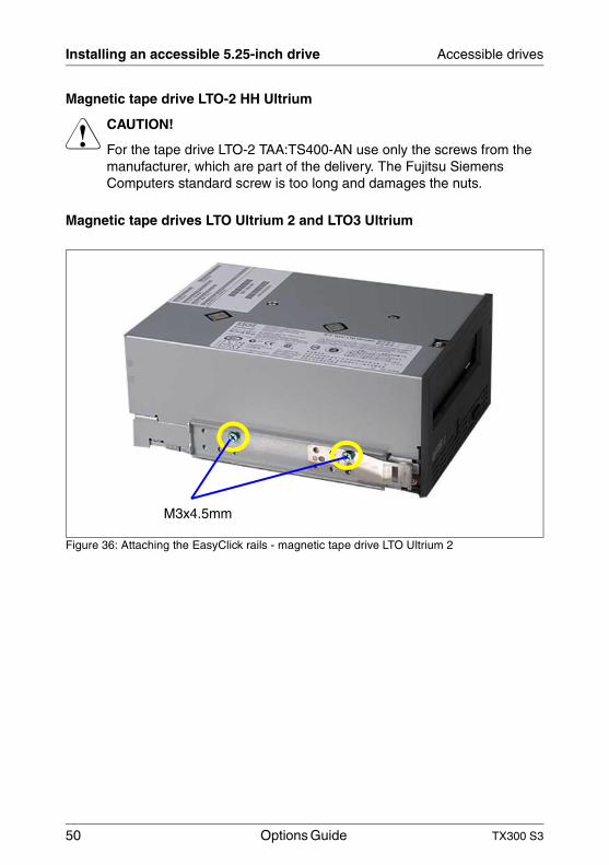
Magnetic tape drive LTO-2 HH Ultrium
V CAUTION!
For the tape drive LTO-2 TAA:TS400-AN use only the screws from the manufacturer, which are part of the delivery. The Fujitsu Siemens Computers standard screw is too long and damages the nuts.
Magnetic tape drives LTO Ultrium 2 and LTO3 Ultrium
Figure 36: Attaching the EasyClick rails - magnetic tape drive LTO Ultrium 2
M3x4.5mm
TX300 S3 Options Guide 51
Accessible drives Installing an accessible 5.25-inch drive
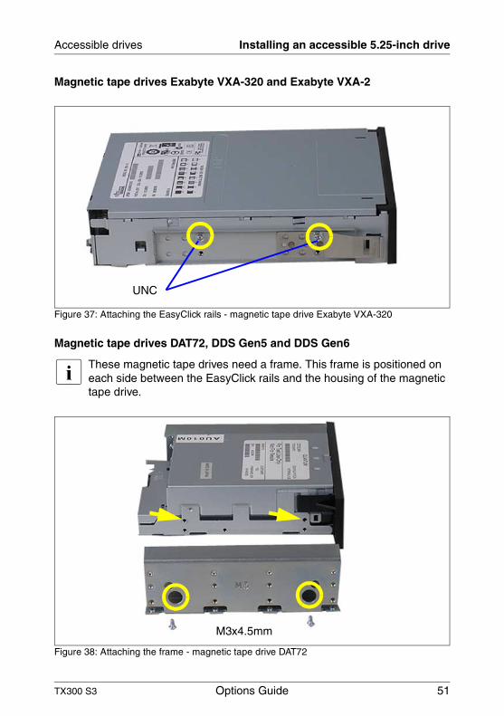
Magnetic tape drives Exabyte VXA-320 and Exabyte VXA-2
Figure 37: Attaching the EasyClick rails - magnetic tape drive Exabyte VXA-320
Magnetic tape drives DAT72, DDS Gen5 and DDS Gen6
I These magnetic tape drives need a frame. This frame is positioned on each side between the EasyClick rails and the housing of the magnetic tape drive.
Figure 38: Attaching the frame - magnetic tape drive DAT72
UNC
M3x4.5mm
52 Options Guide TX300 S3
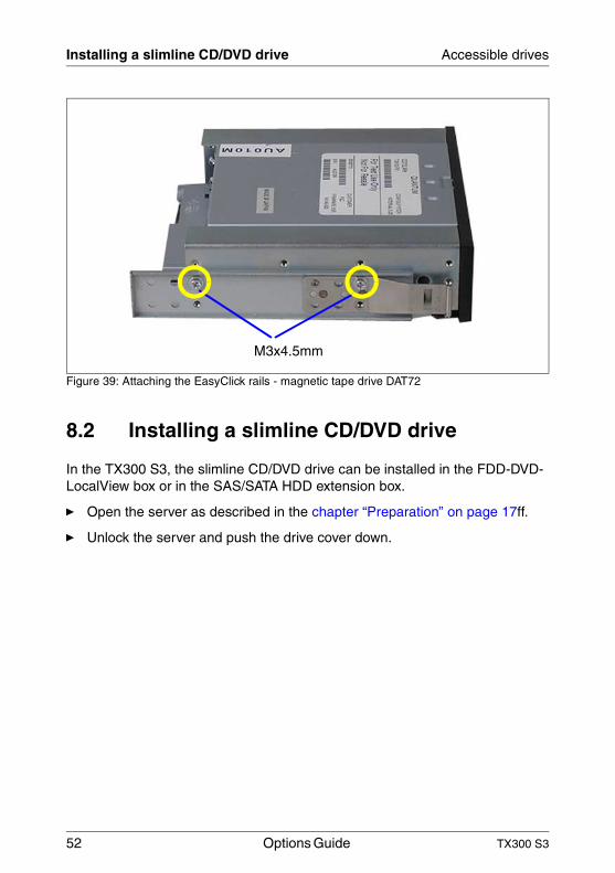
Installing a slimline CD/DVD drive Accessible drives
Figure 39: Attaching the EasyClick rails - magnetic tape drive DAT72
8.2 Installing a slimline CD/DVD drive
In the TX300 S3, the slimline CD/DVD drive can be installed in the FDD-DVD-LocalView box or in the SAS/SATA HDD extension box.
Ê Open the server as described in the chapter “Preparation” on page 17ff.
Ê Unlock the server and push the drive cover down.
M3x4.5mm
TX300 S3 Options Guide 53
Accessible drives Installing a slimline CD/DVD drive
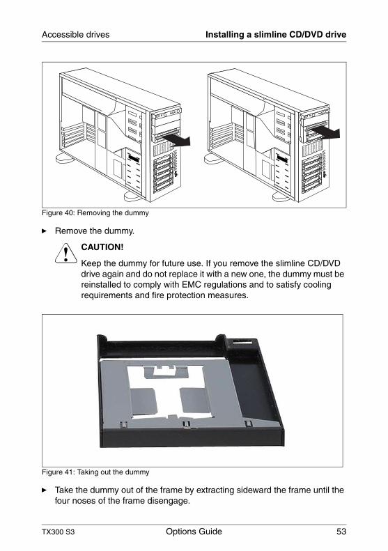
Figure 40: Removing the dummy
Ê Remove the dummy.
V CAUTION!
Keep the dummy for future use. If you remove the slimline CD/DVD drive again and do not replace it with a new one, the dummy must be reinstalled to comply with EMC regulations and to satisfy cooling requirements and fire protection measures.
Figure 41: Taking out the dummy
Ê Take the dummy out of the frame by extracting sideward the frame until the four noses of the frame disengage.
54 Options Guide TX300 S3
Installing a slimline CD/DVD drive Accessible drives
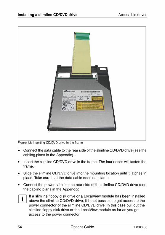
Figure 42: Inserting CD/DVD drive in the frame
Ê Connect the data cable to the rear side of the slimline CD/DVD drive (see the cabling plans in the Appendix).
Ê Insert the slimline CD/DVD drive in the frame. The four noses will fasten the frame.
Ê Slide the slimline CD/DVD drive into the mounting location until it latches in place. Take care that the data cable does not clamp.
Ê Connect the power cable to the rear side of the slimline CD/DVD drive (see the cabling plans in the Appendix).
I If a slimline floppy disk drive or a LocalView module has been installed above the slimline CD/DVD drive, it is not possible to get access to the power connector of the slimline CD/DVD drive. In this case pull out the slimline floppy disk drive or the LocalView module as far as you get access to the power connector.
TX300 S3 Options Guide 55
Accessible drives Installing a slimline CD/DVD drive
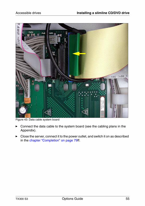
Figure 43: Data cable system board
Ê Connect the data cable to the system board (see the cabling plans in the Appendix).
Ê Close the server, connect it to the power outlet, and switch it on as described in the chapter “Completion” on page 79ff.
56 Options Guide TX300 S3
Installing a slimline floppy disk drive Accessible drives
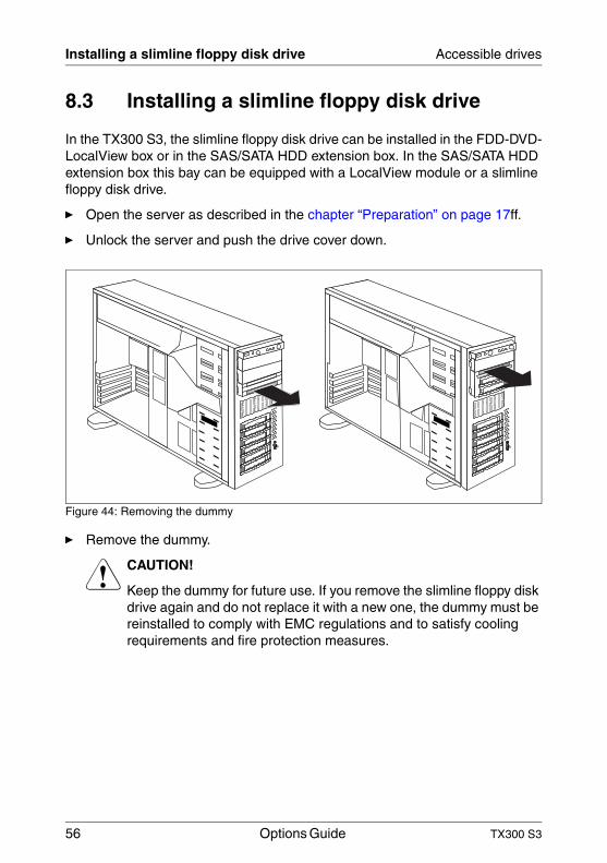
8.3 Installing a slimline floppy disk drive
In the TX300 S3, the slimline floppy disk drive can be installed in the FDD-DVD-LocalView box or in the SAS/SATA HDD extension box. In the SAS/SATA HDD extension box this bay can be equipped with a LocalView module or a slimline floppy disk drive.
Ê Open the server as described in the chapter “Preparation” on page 17ff.
Ê Unlock the server and push the drive cover down.
Figure 44: Removing the dummy
Ê Remove the dummy.
V CAUTION!
Keep the dummy for future use. If you remove the slimline floppy disk drive again and do not replace it with a new one, the dummy must be reinstalled to comply with EMC regulations and to satisfy cooling requirements and fire protection measures.
TX300 S3 Options Guide 57
Accessible drives Installing a slimline floppy disk drive
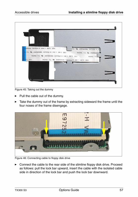
Figure 45: Taking out the dummy
Ê Pull the cable out of the dummy.
Ê Take the dummy out of the frame by extracting sideward the frame until the four noses of the frame disengage.
Figure 46: Connecting cable to floppy disk drive
Ê Connect the cable to the rear side of the slimline floppy disk drive. Proceed as follows: pull the lock bar upward, insert the cable with the isolated cable side in direction of the lock bar and push the lock bar downward.
58 Options Guide TX300 S3
Installing a slimline floppy disk drive Accessible drives
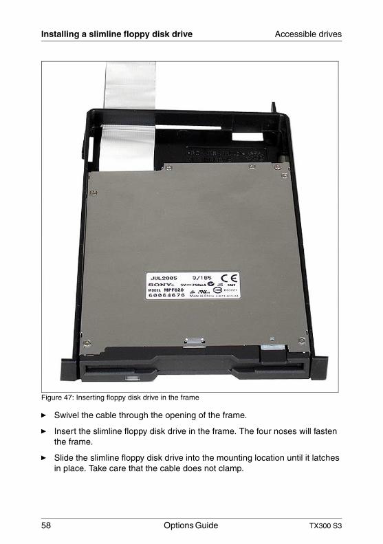
Figure 47: Inserting floppy disk drive in the frame
Ê Swivel the cable through the opening of the frame.
Ê Insert the slimline floppy disk drive in the frame. The four noses will fasten the frame.
Ê Slide the slimline floppy disk drive into the mounting location until it latches in place. Take care that the cable does not clamp.
TX300 S3 Options Guide 59
Accessible drives Installing a LocalView module
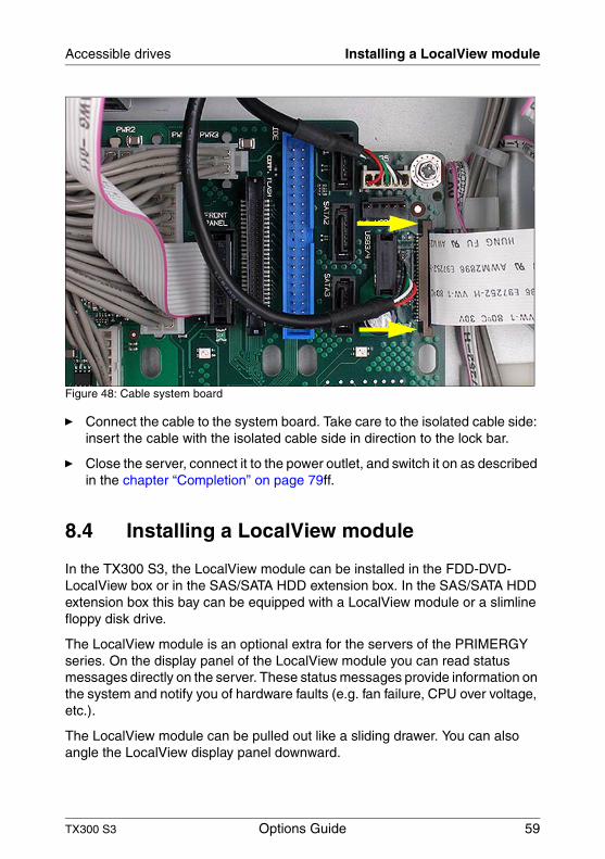
Figure 48: Cable system board
Ê Connect the cable to the system board. Take care to the isolated cable side: insert the cable with the isolated cable side in direction to the lock bar.
Ê Close the server, connect it to the power outlet, and switch it on as described in the chapter “Completion” on page 79ff.
8.4 Installing a LocalView module
In the TX300 S3, the LocalView module can be installed in the FDD-DVD-LocalView box or in the SAS/SATA HDD extension box. In the SAS/SATA HDD extension box this bay can be equipped with a LocalView module or a slimline floppy disk drive.
The LocalView module is an optional extra for the servers of the PRIMERGY series. On the display panel of the LocalView module you can read status messages directly on the server. These status messages provide information on the system and notify you of hardware faults (e.g. fan failure, CPU over voltage, etc.).
The LocalView module can be pulled out like a sliding drawer. You can also angle the LocalView display panel downward.
60 Options Guide TX300 S3
Installing a LocalView module Accessible drives
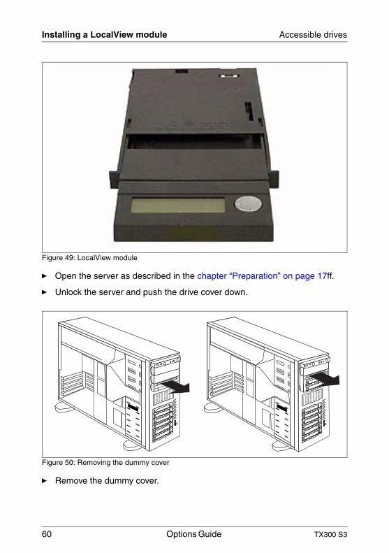
Figure 49: LocalView module
Ê Open the server as described in the chapter “Preparation” on page 17ff.
Ê Unlock the server and push the drive cover down.
Figure 50: Removing the dummy cover
Ê Remove the dummy cover.
TX300 S3 Options Guide 61
Accessible drives Installing the FDD-DVD-LocalView box
V CAUTION!
Keep the section “Installing an accessible 5.25-inch drive” on page 47dummy cover for future use. If you remove the LocalView module again and do not replace it with a new one, the dummy cover must be reinstalled to comply with EMC regulations and to satisfy cooling requirements and fire protection measures.
Ê Slide the LocalView module into the mounting location until it latches in place.
Ê Attach the Con3 connector of the I2C cable (T26139-Y3718-V601) to the connector on the rear of the LocalView module.
Ê Close the server, connect it to the power outlet, and switch it on as described in the chapter “Completion” on page 79ff.
I Further information on operation and display modes is provided in the documentation for the LocalView module.
8.5 Installing the FDD-DVD-LocalView box
In the third, lowest 5.25-inch bay a multibay (FDD-DVD-LocalView box) can be installed.
Ê Open the server and remove the front cover or rack front cover as described in the in the chapter “Preparation” on page 17ff.
Ê If a drive has been installed in the lowest 5.25-inch bay, remove the drive and install it in a free 5.25-inch bay (see section “Installing an accessible 5.25-inch drive” on page 47).
62 Options Guide TX300 S3
Installing the SAS/SATA HDD extension box Accessible drives
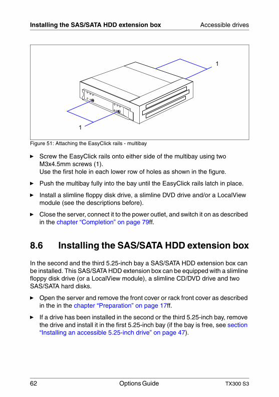
Figure 51: Attaching the EasyClick rails - multibay
Ê Screw the EasyClick rails onto either side of the multibay using two M3x4.5mm screws (1). Use the first hole in each lower row of holes as shown in the figure.
Ê Push the multibay fully into the bay until the EasyClick rails latch in place.
Ê Install a slimline floppy disk drive, a slimline DVD drive and/or a LocalView module (see the descriptions before).
Ê Close the server, connect it to the power outlet, and switch it on as described in the chapter “Completion” on page 79ff.
8.6 Installing the SAS/SATA HDD extension box
In the second and the third 5.25-inch bay a SAS/SATA HDD extension box can be installed. This SAS/SATA HDD extension box can be equipped with a slimline floppy disk drive (or a LocalView module), a slimline CD/DVD drive and two SAS/SATA hard disks.
Ê Open the server and remove the front cover or rack front cover as described in the in the chapter “Preparation” on page 17ff.
Ê If a drive has been installed in the second or the third 5.25-inch bay, remove the drive and install it in the first 5.25-inch bay (if the bay is free, see section “Installing an accessible 5.25-inch drive” on page 47).
1
1
TX300 S3 Options Guide 63
Accessible drives Installing the SAS/SATA HDD extension box
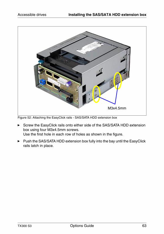
Figure 52: Attaching the EasyClick rails - SAS/SATA HDD extension box
Ê Screw the EasyClick rails onto either side of the SAS/SATA HDD extension box using four M3x4.5mm screws. Use the first hole in each row of holes as shown in the figure.
Ê Push the SAS/SATA HDD extension box fully into the bay until the EasyClick rails latch in place.
M3x4.5mm
64 Options Guide TX300 S3
Installing the SAS/SATA HDD extension box Accessible drives
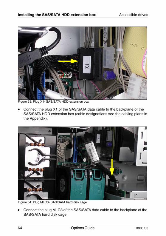
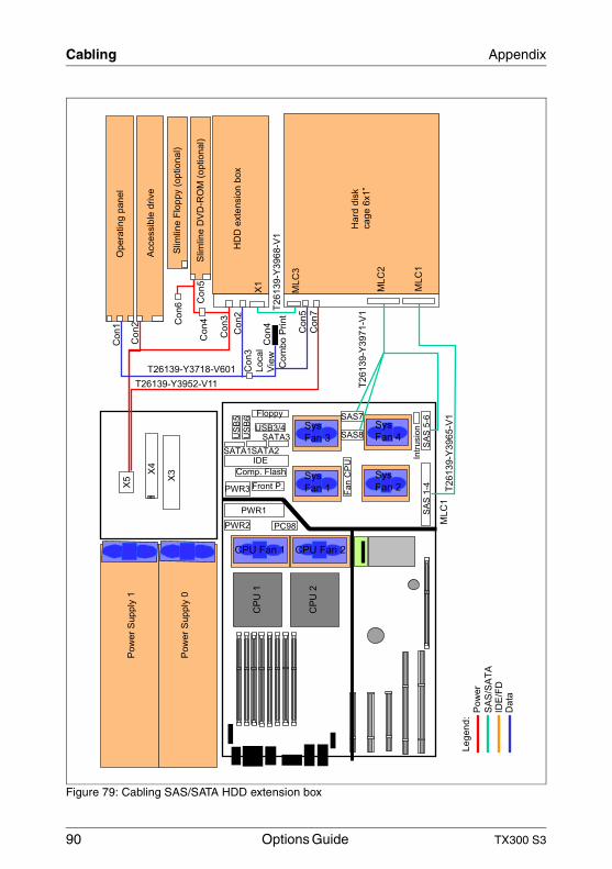
Figure 53: Plug X1- SAS/SATA HDD extension box
Ê Connect the plug X1 of the SAS/SATA data cable to the backplane of the SAS/SATA HDD extension box (cable designations see the cabling plans in the Appendix).
Figure 54: Plug MLC3- SAS/SATA hard disk cage
Ê Connect the plug MLC3 of the SAS/SATA data cable to the backplane of the SAS/SATA hard disk cage.
TX300 S3 Options Guide 65
Accessible drives Installing the SAS/SATA HDD extension box
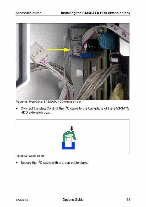
Figure 55: Plug Con2- SAS/SATA HDD extension box
Ê Connect the plug Con2 of the I2C cable to the backplane of the SAS/SATA HDD extension box.
Figure 56: Cable clamp
Ê Secure the I2C cable with a green cable clamp.
Con2
66 Options Guide TX300 S3
Installing the SAS/SATA HDD extension box Accessible drives
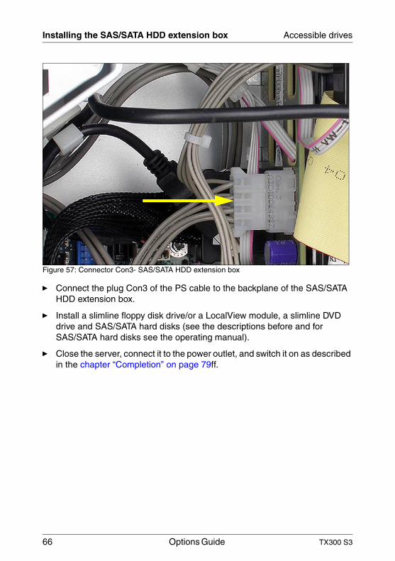
Figure 57: Connector Con3- SAS/SATA HDD extension box
Ê Connect the plug Con3 of the PS cable to the backplane of the SAS/SATA HDD extension box.
Ê Install a slimline floppy disk drive/or a LocalView module, a slimline DVD drive and SAS/SATA hard disks (see the descriptions before and for SAS/SATA hard disks see the operating manual).
Ê Close the server, connect it to the power outlet, and switch it on as described in the chapter “Completion” on page 79ff.
TX300 S3 Options Guide 67
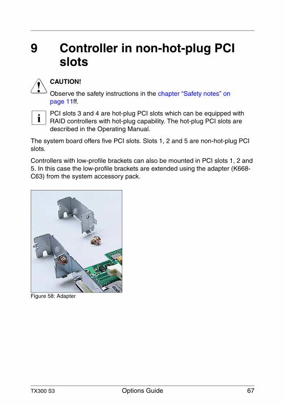
9 Controller in non-hot-plug PCI slots
V CAUTION!
Observe the safety instructions in the chapter “Safety notes” on page 11ff.
I PCI slots 3 and 4 are hot-plug PCI slots which can be equipped with RAID controllers with hot-plug capability. The hot-plug PCI slots are described in the Operating Manual.
The system board offers five PCI slots. Slots 1, 2 and 5 are non-hot-plug PCI slots.
Controllers with low-profile brackets can also be mounted in PCI slots 1, 2 and 5. In this case the low-profile brackets are extended using the adapter (K668-C63) from the system accessory pack.
Figure 58: Adapter
68 Options Guide TX300 S3
Installing a controller Controller in non-hot-plug PCI slots
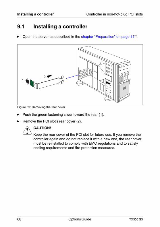
9.1 Installing a controller
Ê Open the server as described in the chapter “Preparation” on page 17ff.
Figure 59: Removing the rear cover
Ê Push the green fastening slider toward the rear (1).
Ê Remove the PCI slot’s rear cover (2).
V CAUTION!
Keep the rear cover of the PCI slot for future use. If you remove the controller again and do not replace it with a new one, the rear cover must be reinstalled to comply with EMC regulations and to satisfy cooling requirements and fire protection measures.
2
1
TX300 S3 Options Guide 69
Controller in non-hot-plug PCI slots Installing a controller
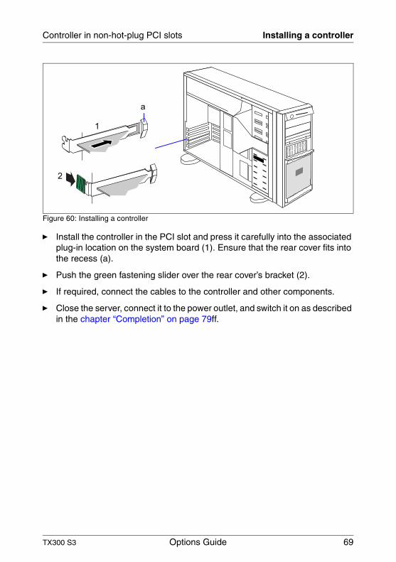
Figure 60: Installing a controller
Ê Install the controller in the PCI slot and press it carefully into the associated plug-in location on the system board (1). Ensure that the rear cover fits into the recess (a).
Ê Push the green fastening slider over the rear cover’s bracket (2).
Ê If required, connect the cables to the controller and other components.
Ê Close the server, connect it to the power outlet, and switch it on as described in the chapter “Completion” on page 79ff.
1
2
a

TX300 S3 Options Guide 71
10 Parallel interface for printersV CAUTION!
Observe the safety instructions in the chapter “Safety notes” on page 11ff.
10.1 Installing a parallel interface
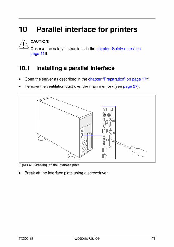
Ê Open the server as described in the chapter “Preparation” on page 17ff.
Ê Remove the ventilation duct over the main memory (see page 27).
Figure 61: Breaking off the interface plate
Ê Break off the interface plate using a screwdriver.
72 Options Guide TX300 S3
Installing a parallel interface Parallel interface for printers
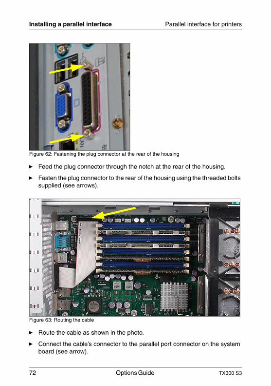
Figure 62: Fastening the plug connector at the rear of the housing
Ê Feed the plug connector through the notch at the rear of the housing.
Ê Fasten the plug connector to the rear of the housing using the threaded bolts supplied (see arrows).
Figure 63: Routing the cable
Ê Route the cable as shown in the photo.
Ê Connect the cable’s connector to the parallel port connector on the system board (see arrow).
TX300 S3 Options Guide 73
Parallel interface for printers Installing a parallel interface
Ê Reinstall the ventilation duct over the main memory (see page 29).
Ê Close the server, connect it to the power outlet, and switch it on as described in the chapter “Completion” on page 79ff.

TX300 S3 Options Guide 75
11 Converting from the floorstand model to the rack model
V CAUTION!
Observe the safety instructions in the chapter “Safety notes” on page 11ff.
Ê Open the server and remove the front cover as described in the chapter “Preparation” on page 17ff.
I The front cover is no longer required.
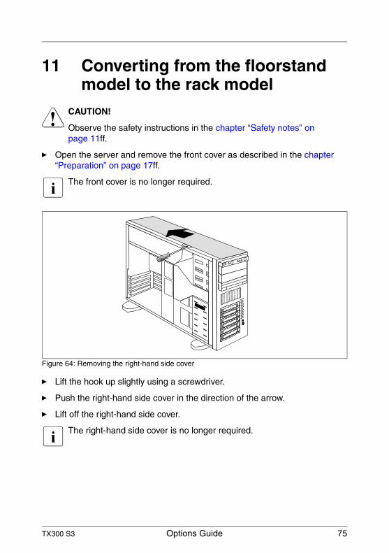
Figure 64: Removing the right-hand side cover
Ê Lift the hook up slightly using a screwdriver.
Ê Push the right-hand side cover in the direction of the arrow.
Ê Lift off the right-hand side cover.
I The right-hand side cover is no longer required.
76 Options Guide TX300 S3
Converting from the floorstand model to the rack model
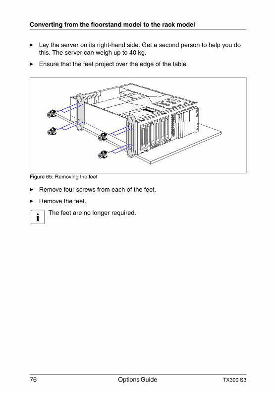
Ê Lay the server on its right-hand side. Get a second person to help you do this. The server can weigh up to 40 kg.
Ê Ensure that the feet project over the edge of the table.
Figure 65: Removing the feet
Ê Remove four screws from each of the feet.
Ê Remove the feet.
I The feet are no longer required.
TX300 S3 Options Guide 77
Converting from the floorstand model to the rack model
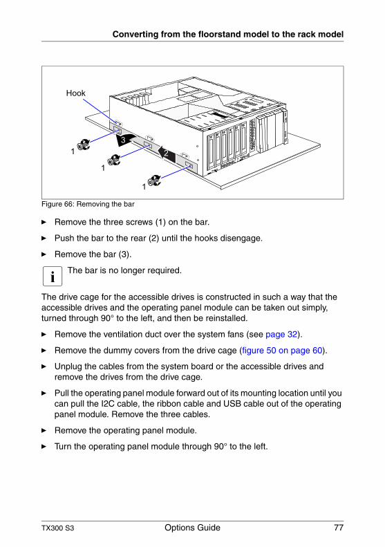
Figure 66: Removing the bar
Ê Remove the three screws (1) on the bar.
Ê Push the bar to the rear (2) until the hooks disengage.
Ê Remove the bar (3).
I The bar is no longer required.
The drive cage for the accessible drives is constructed in such a way that the accessible drives and the operating panel module can be taken out simply, turned through 90° to the left, and then be reinstalled.
Ê Remove the ventilation duct over the system fans (see page 32).
Ê Remove the dummy covers from the drive cage (figure 50 on page 60).
Ê Unplug the cables from the system board or the accessible drives and remove the drives from the drive cage.
Ê Pull the operating panel module forward out of its mounting location until you can pull the I2C cable, the ribbon cable and USB cable out of the operating panel module. Remove the three cables.
Ê Remove the operating panel module.
Ê Turn the operating panel module through 90° to the left.
Hook
1
1
1
3
2
78 Options Guide TX300 S3
Converting from the floorstand model to the rack model
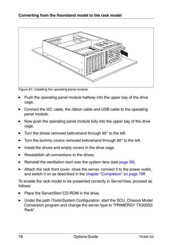
Figure 67: Installing the operating panel module
Ê Push the operating panel module halfway into the upper bay of the drive cage.
Ê Connect the I2C cable, the ribbon cable and USB cable to the operating panel module.
Ê Now push the operating panel module fully into the upper bay of the drive cage.
Ê Turn the drives removed beforehand through 90° to the left.
Ê Turn the dummy covers removed beforehand through 90° to the left.
Ê Install the drives and empty covers in the drive cage.
Ê Reestablish all connections to the drives.
Ê Reinstall the ventilation duct over the system fans (see page 39).
Ê Attach the rack front cover, close the server, connect it to the power outlet, and switch it on as described in the chapter “Completion” on page 79ff.
To enable the rack model to be presented correctly in ServerView, proceed as follows:
Ê Place the ServerStart CD-ROM in the drive.
Ê Under the path \Tools\System Configuration start the SCU_Chassis Model Conversion program and change the server type to "PRIMERGY TX300S3 Rack".
TX300 S3 Options Guide 79
12 CompletionV CAUTION!
Observe the safety instructions in the chapter “Safety notes” on page 11ff.
12.1 Floorstand model
12.1.1 Attaching the front cover
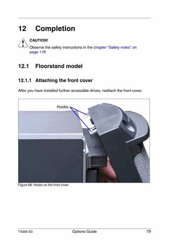
After you have installed further accessible drives, reattach the front cover.
Figure 68: Hooks on the front cover
Hooks
80 Options Guide TX300 S3
Floorstand model Completion
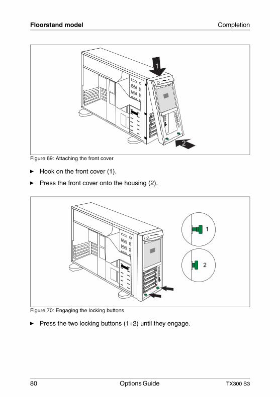
Figure 69: Attaching the front cover
Ê Hook on the front cover (1).
Ê Press the front cover onto the housing (2).
Figure 70: Engaging the locking buttons
Ê Press the two locking buttons (1+2) until they engage.
1
2
2
1
TX300 S3 Options Guide 81
Completion Floorstand model
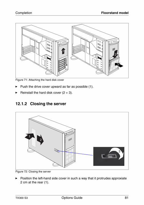
Figure 71: Attaching the hard disk cover
Ê Push the drive cover upward as far as possible (1).
Ê Reinstall the hard disk cover (2 + 3).
12.1.2 Closing the server
Figure 72: Closing the server
Ê Position the left-hand side cover in such a way that it protrudes approxiate 2 cm at the rear (1).
1
2
3
2
1
3
82 Options Guide TX300 S3
Rack model Completion
Ê Push the left-hand side cover all the way forward (2).
Ê Push down the latch to lock the left-hand side cover (3).
Ê Insert the key.
Ê Lock the server.
Ê Connect all power plugs to the power outlets.
Ê Press the on/off key to start up the server.
12.2 Rack model
12.2.1 Attaching the rack front cover
Reattach the rack front cover after implementing the following extensions:
– Installation of further accessible drives
– Conversion of the floorstand model to a rack model
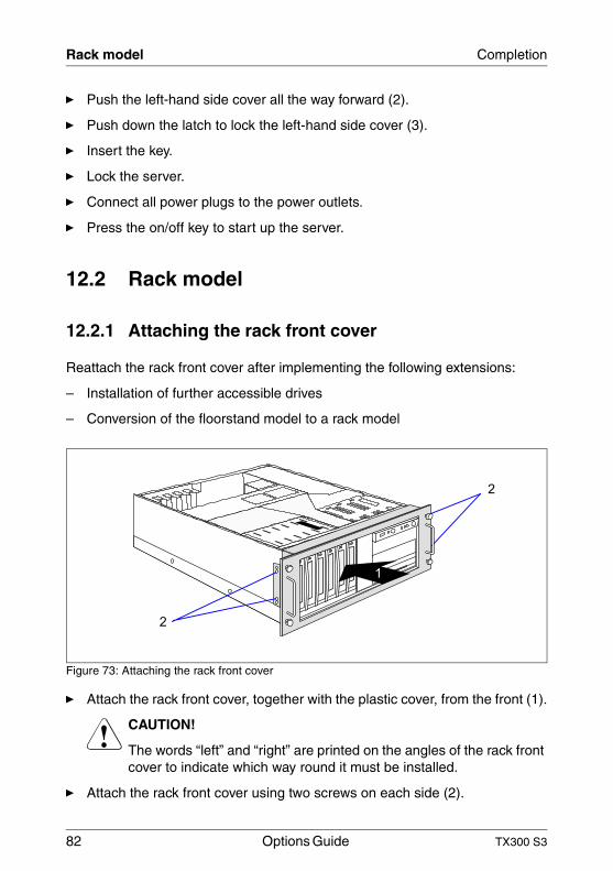
Figure 73: Attaching the rack front cover
Ê Attach the rack front cover, together with the plastic cover, from the front (1).
V CAUTION!
The words “left” and “right” are printed on the angles of the rack front cover to indicate which way round it must be installed.
Ê Attach the rack front cover using two screws on each side (2).
2
2
1
TX300 S3 Options Guide 83
Completion Rack model
12.2.2 Closing the server
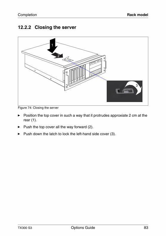
Figure 74: Closing the server
Ê Position the top cover in such a way that it protrudes approxiate 2 cm at the rear (1).
Ê Push the top cover all the way forward (2).
Ê Push down the latch to lock the left-hand side cover (3).
1
3
2
84 Options Guide TX300 S3
Rack model Completion
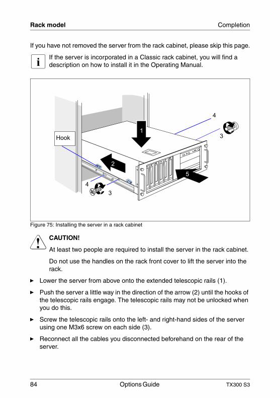
If you have not removed the server from the rack cabinet, please skip this page.
I If the server is incorporated in a Classic rack cabinet, you will find a description on how to install it in the Operating Manual.
Figure 75: Installing the server in a rack cabinet
V CAUTION!
At least two people are required to install the server in the rack cabinet.
Do not use the handles on the rack front cover to lift the server into the rack.
Ê Lower the server from above onto the extended telescopic rails (1).
Ê Push the server a little way in the direction of the arrow (2) until the hooks of the telescopic rails engage. The telescopic rails may not be unlocked when you do this.
Ê Screw the telescopic rails onto the left- and right-hand sides of the server using one M3x6 screw on each side (3).
Ê Reconnect all the cables you disconnected beforehand on the rear of the server.
Hook
4
3
4
31
2
5
TX300 S3 Options Guide 85
Completion Rack model
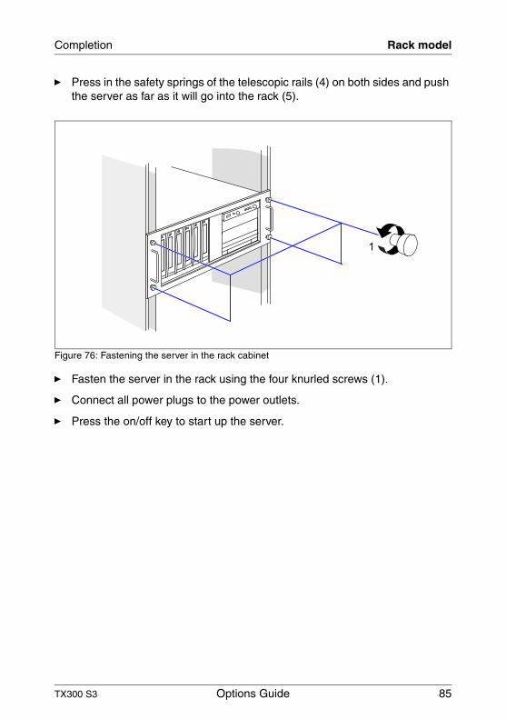
Ê Press in the safety springs of the telescopic rails (4) on both sides and push the server as far as it will go into the rack (5).
Figure 76: Fastening the server in the rack cabinet
Ê Fasten the server in the rack using the four knurled screws (1).
Ê Connect all power plugs to the power outlets.
Ê Press the on/off key to start up the server.
1

86 Options Guide TX300 S3
Rack model Completion

TX300 S3 Options Guide 87
13 Appendix
13.1 Cabling
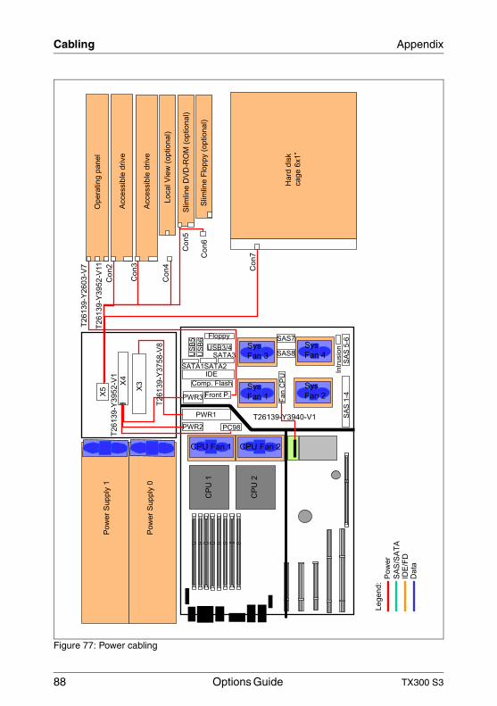
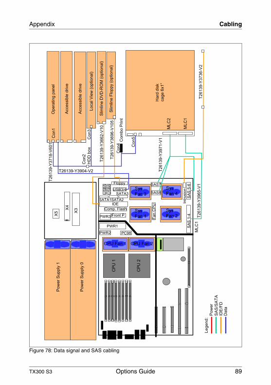
You will find suggestions for cabling on the next pages.
88 Options Guide TX300 S3
Cabling Appendix
Figure 77: Power cabling
CPU Fan 1
Le
ge
nd
:P
ow
er
SA
S/S
AT
AID
E/F
DD
ata
CP
U1
CP
U2
Pow
er
Supply
1
Pow
er
Supply
0
CPU Fan 2
Sys
Fan 1
Sys
Fan 3
Sys
Fan 2
Sys
Fan 4
Hard
dis
k
cage 6
x1”
T26139-Y
2603-V
7
Co
n2
Opera
ting p
anel
Accessib
le d
rive
Accessib
le d
rive
Local V
iew
(optional)
Slim
line D
VD
-RO
M (
optional)
Slim
line F
loppy (
optional)
Co
n3
Co
n4
Co
n5
Co
n6
Co
n7
T26139-Y
3952-V
11
T26139-Y
3758-V
8
X5
X4
X3
T26139-Y
3952-V
1
T26139-Y3940-V1 SA
S 1
-4S
AS
5-6
Intr
usio
n
Fa
n C
PU
US
B5
US
B6
Floppy
USB3/4
IDE
SAS7
SAS8
PWR3
PWR2
PWR1
PC98
SATA1SATA2
SATA3
Comp. Flash
Front P.
TX300 S3 Options Guide 89
Appendix Cabling
Figure 78: Data signal and SAS cabling
CPU Fan 1
Le
ge
nd
:P
ow
er
SA
S/S
AT
AID
E/F
DD
ata
CP
U1
CP
U2
Pow
er
Supply
1
Pow
er
Supply
0
CPU Fan 2
Sys
Fan 1
Sys
Fan 3
Sys
Fan 2
Sys
Fan 4
Hard
dis
k
cage 6
x1”
Co
n2
HD
D b
ox
Opera
ting p
anel
Accessib
le d
rive
Accessib
le d
rive
Local V
iew
(optional)
Slim
line D
VD
-RO
M (
optional)
Slim
line F
loppy (
optional)
Co
n3
Co
n4 Co
n5
T26139-Y
3736-V
2
X5
X4
X3
SA
S 1
-4S
AS
5-6
Intr
usio
n
Fa
n C
PU
US
B5
US
B6
Floppy
USB3/4
IDE
SAS7
SAS8
PWR3
PWR2
PWR1
PC98
SATA1SATA2
SATA3
Comp. Flash
Front P.
Com
bo P
rint
T26139-Y
3718-V
601
T26139-Y
3662-V
10
T26139-Y
3696-V
105
T26139-Y3904-V2M
LC
2
ML
C1
ML
C1
T26139-Y
3971-V
1
T26139-Y
3965-V
1
Co
n1
90 Options Guide TX300 S3
Cabling Appendix
Figure 79: Cabling SAS/SATA HDD extension box
CPU Fan 1
Le
ge
nd
:P
ow
er
SA
S/S
AT
AID
E/F
DD
ata
CP
U1
CP
U2
Pow
er
Supply
1
Pow
er
Supply
0
CPU Fan 2
Sys
Fan 1
Sys
Fan 3
Sys
Fan 2
Sys
Fan 4
Hard
dis
k
cage 6
x1”
Opera
ting p
anel
Accessib
le d
rive
Slim
line D
VD
-RO
M (
optional)
Slim
line F
loppy (
optional)
X5
X4
X3
SA
S 1
-4S
AS
5-6
Intr
usio
n
Fa
n C
PU
US
B5
US
B6
Floppy
USB3/4
IDE
SAS7
SAS8
PWR3
PWR2
PWR1
PC98
SATA1SATA2
SATA3
Comp. Flash
Front P.
T26139-Y3718-V601
ML
C2
ML
C1
ML
C1
T26139-Y
3971-V
1
T26139-Y
3965-V
1
Co
n1
Co
n3
Lo
ca
l
Vie
wC
on
4
Co
n5
Com
bo P
rint
Co
n7
ML
C3
X1
Co
n3
Co
n2
Co
n5
Co
n6
Co
n4
Co
n2
HD
D e
xte
nsio
n b
ox
T26139-Y
3968-V
1
T26139-Y3952-V11
TX300 S3 Options Guide 91
Appendix Cabling
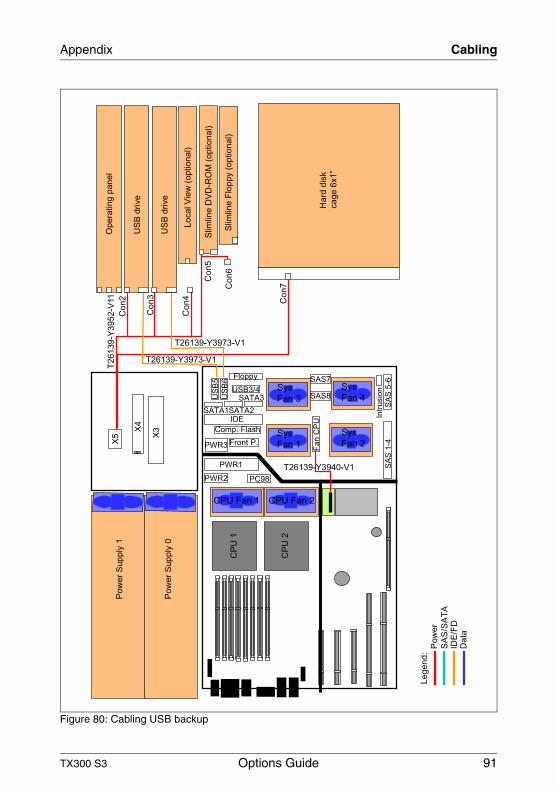
Figure 80: Cabling USB backup
CPU Fan 1
Le
ge
nd
:P
ow
er
SA
S/S
AT
AID
E/F
DD
ata
CP
U1
CP
U2
Pow
er
Supply
1
Pow
er
Supply
0
CPU Fan 2
Sys
Fan 1
Sys
Fan 3
Sys
Fan 2
Sys
Fan 4
Hard
dis
k
cage 6
x1”
Co
n2
Opera
ting p
anel
US
B d
rive
US
B d
rive
Local V
iew
(optional)
Slim
line D
VD
-RO
M (
optional)
Slim
line F
loppy (
optional)
Co
n3
Co
n4
Co
n5
Co
n6
Co
n7
T26139-Y
3952-V
11
X5
X4
X3
T26139-Y3940-V1 SA
S 1
-4S
AS
5-6
Intr
usio
n
Fa
n C
PU
US
B5
US
B6
Floppy
USB3/4
IDE
SAS7
SAS8
PWR3
PWR2
PWR1
PC98
SATA1SATA2
SATA3
Comp. Flash
Front P.
T26139-Y3973-V1
T26139-Y3973-V1
92 Options Guide TX300 S3
Cabling Appendix
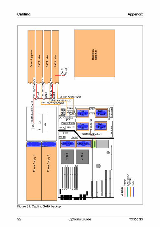
Figure 81: Cabling SATA backup
CPU Fan 1
Le
ge
nd
:P
ow
er
SA
S/S
AT
AID
E/F
DD
ata
CP
U1
CP
U2
Pow
er
Supply
1
Pow
er
Supply
0
CPU Fan 2
Sys
Fan 1
Sys
Fan 3
Sys
Fan 2
Sys
Fan 4
Hard
dis
k
cage 6
x1”
Co
n2
Opera
ting p
anel
SA
TA
drive
SA
TA
drive
Co
n3
Co
n4
Co
n5
Co
n6
X5
X4
X3
T26139-Y3940-V1 SA
S 1
-4S
AS
5-6
Intr
usio
n
Fa
n C
PU
US
B5
US
B6
Floppy
USB3/4
IDE
SAS7
SAS8
PWR3
PWR2
PWR1
PC98
SATA1SATA2
SATA3
Comp. Flash
Front P.
SA
TA
drive
T26139-Y3958-V201T26139-Y3958-V201
T26139-Y3958-V201
T26139-Y
3952-V
11
T26139-Y
3930-V
1
T26139-Y
3930-V
1
T26139-Y
3930-V
1
TX300 S3 Options Guide 93
Appendix Cabling
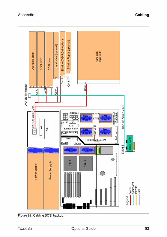
Figure 82: Cabling SCSI backup
CPU Fan 1
Le
ge
nd
:P
ow
er
SA
S/S
AT
AID
E/F
DD
ata
CP
U1
CP
U2
Pow
er
Supply
1
Pow
er
Supply
0
CPU Fan 2
Sys
Fan 1
Sys
Fan 3
Sys
Fan 2
Sys
Fan 4
Hard
dis
k
cage 6
x1”
Co
n2
Opera
ting p
anel
SC
SI drive
SC
SI drive
Local V
iew
(optional)
Slim
line D
VD
-RO
M (
optional)
Slim
line F
loppy (
optional)
Co
n3
Co
n4
Co
n5
Co
n6
Co
n7
X5
X4
X3
T26139-Y3940-V1 SA
S 1
-4S
AS
5-6
Intr
usio
n
Fa
n C
PU
US
B5
US
B6
Floppy
USB3/4
IDE
SAS7
SAS8
PWR3
PWR2
PWR1
PC98
SATA1SATA2
SATA3
Comp. Flash
Front P.
T26139-Y
3952-V
11L
VD
/SE
Te
rmin
ato
r
LV
D/S
E
SC
SI
co
ntr
.
T26139-Y
3967-V
101
94 Options Guide TX300 S3
Cabling Appendix
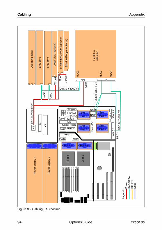
Figure 83: Cabling SAS backup
CPU Fan 1
Le
ge
nd
:P
ow
er
SA
S/S
AT
AID
E/F
DD
ata
CP
U1
CP
U2
Pow
er
Supply
1
Pow
er
Supply
0
CPU Fan 2
Sys
Fan 1
Sys
Fan 3
Sys
Fan 2
Sys
Fan 4
Hard
dis
k
cage 6
x1”
Opera
ting p
anel
SA
S d
rive
SA
S d
rive
Local V
iew
(optional)
Slim
line D
VD
-RO
M (
optional)
Slim
line F
loppy (
optional)
X5
X4
X3
SA
S 1
-4S
AS
5-6
Intr
usio
n
Fa
n C
PU
US
B5
US
B6
Floppy
USB3/4
IDE
SAS7
SAS8
PWR3
PWR2
PWR1
PC98
SATA1SATA2
SATA3
Comp. Flash
Front P.
ML
C2
ML
C1
ML
C1
T26139-Y
3971-V
1
T26139-Y
3965-V
1
Co
n5
Co
n6
Co
n2
ML
C3
Co
n7C
on
4
Co
n3
T26139-Y3969-V1
T26139-Y
3952-V
11
TX300 S3 Options Guide 95
AbbreviationsAC
Alternating Current
ANSIAmerican National Standard Institut
ASR&RAutomatic Server Reconfiguration and Restart
BIOSBasic Input-Output System
BMCBaseboard Management Controller
CCCache Coherency
CDCompact Disk
CD-ROMCompact Disk-Read Only Memory
CHSCylinder Head Sector
CMOSComplementary Metal Oxide Semiconductor
COMCommunication
CPUCentral Processing Unit
DCDirect Current
96 Options Guide TX300 S3
Abbreviations
DIMMDual Inline Memory Module
DIPDual Inline Package
DMADirect Memory Access
DMIDesktop Management Interface
ECCErrror Checking and Correcting
ECPExtended Capabilities Port
EEPROMElectrically Erasable Programmable Read-Only Memory
EMCElectroMagnetic Compatibility)
EMPEmergency Management Port
EPPEnhanced Parallel Port
ESDElectroStatic Discharge
FPCFront Panel Controller
FRUField Replaceable Unit
FSBFront Side Bus
TX300 S3 Options Guide 97
Abbreviations
GAMGlobal Array Manager
GUIGraphical User Interface
HDDHard Disk Drive
HSCHot-Swap Controller
I²CInter-Integrated Circuit
I/OInput/Output
ICMIntelligent Chassis Management
IDIdentification
IDEIntergrated Drive Electronics
IOOPIntetelligent Organization of PCI
iRMCintegrated Remote Management Controller
IRQInterrupt Request Line
LANLocal Area Network
LBALogical Block Address
98 Options Guide TX300 S3
Abbreviations
LCDLiquid Crystal Display
LUNLogical Unit Number
LVDLow-Voltage Differential SCSI
MMFMulti Mode Faser
MRLManually Retention Latch
NMINon Maskable Interrupt
NVRAMNon Volatile Random Access Memory
OSOperating System
PCIPeripheral Component Interconnect
PDAPrefailure Detection and Analysing
POSTPower ON Self Test
RAIDRedundant Arrays of Independent Disks
RAMRandom Access Memory
ROMRead-Only Memory
TX300 S3 Options Guide 99
Abbreviations
RSBRemote Service Board
RTCReal Time Clock
RTDSRemote Test- und Diagnose-System
SAF-TESCSI Accessed Fault-Tolerance Enclosures
SASSerial Attached SCSI
SATASerial ATA
SBESingle Bit Error
SCASingle Connector Attachment
SCSISmall Computer System Interface
SDDCSingle Device Data Correction
SDRSensor Data Record
SDRAMSynchronous Dynamic Random Access Memory
SELSystem Event Log
SMISystem Management Interrupt
100 Options Guide TX300 S3
Abbreviations
SSUSystem Setup Utility
SVGASuper Video Graphics Adapter
USBUniversal Serial Bus
VGAVideo Graphics Adapter
TX300 S3 Options Guide 101
Related publicationsPRIMERGY manuals are available as PDF file on the ServerBooks CD. The ServerBooks CD is part of the PRIMERGY ServerView Suite delivered with each server system.
The current versions of the required manuals can be downloaded free of charge as PDF files from the Internet. The overview page showing the online documen-tation available on the Internet can be found via the URL:http://manuals.fujitsu-siemens.com. For the documentation of the PRIMERGY servers choose the navigation point industry standard servers.
[1] Safety notes and other important information
[2] Warranty
[3] Guarantee
[4] Returning used devices
[5] PRIMECENTER Rack Technical Manual
[6] DataCenter Rack Technical Manual
[7] 19 inch rack Technical Manual
[8] LocalView User Manual
[9] PRIMERGY ServerView Suite ServerStartUser Manual
[10] PRIMERGY ServerView Suite ServerViewServer ManagementUser Manual
102 Options Guide TX300 S3
Related Publications
[11] PRIMERGY ServerView Suite ServerView S2Server ManagementUser Manual
[12] ServerView ExtensionServerView Extension for HP OpenView NNM
[13] ServerView/Plus for Tivoli
[14] PRIMERGY ServerView Suite RemoteViewUser Manual
[15] PRIMERGY TX300 S3 Operating Manual
[16] System Board D2129 Technical Manual
[17] BIOS-Setup Reference Manual
[18] Integrated Mirroring User’s Guide
[19] Global Array Manager Client Software User’s Guide
[20] Global Array Manager Server Software User’s Guide
TX300 S3 Options Guide 103
IndexAaccessible drives 7, 47
CchipDISK 7controller 8, 68conversion of floorstand module to
rack model 8
Ddual operation 31, 40
EESD (devices sensitive to electrostatic
discharge) 15ESD-sensitive devices 15
Ffloorstand to rack model
conversion 75front cover 18, 79
Hheat sink 42
Iinformation material 6
Llight-emitting diode (LED) 15lithium battery 14LocalView module 7, 59
Mmagnetic tape drive
DAT72 52Exabyte VXA-320 51
main memory 7, 25meaning
of the symbols 8multiprocessor operating system 31,
40
Nnotational conventions 8note about the laser 15
Pparallel interface 8, 71processor 6, 31
Rrack front cover 23, 82RemoteView 7ROMB 7
Ttarget group 5
Vventilation duct, front 32ventilation duct, main memory 27


Comments on PRIMERGY TX300 S3Server
TX300 S3
CommentsSuggestionsCorrections
✁
Submitted by
Fujitsu Siemens Computers GmbHUser Documentation81730 MünchenGermany
Fax: (++49) 700 / 372 00000
email: [email protected]://manuals.fujitsu-siemens.com

Comments on PRIMERGY TX300 S3Server
TX300 S3
CommentsSuggestionsCorrections
✁
Submitted by
Fujitsu Siemens Computers GmbHUser Documentation81730 MünchenGermany
Fax: (++49) 700 / 372 00000
email: [email protected]://manuals.fujitsu-siemens.com

Information on this document On April 1, 2009, Fujitsu became the sole owner of Fujitsu Siemens Compu-ters. This new subsidiary of Fujitsu has been renamed Fujitsu Technology So-lutions.
This document from the document archive refers to a product version which was released a considerable time ago or which is no longer marketed.
Please note that all company references and copyrights in this document have been legally transferred to Fujitsu Technology Solutions.
Contact and support addresses will now be offered by Fujitsu Technology So-lutions and have the format …@ts.fujitsu.com.
The Internet pages of Fujitsu Technology Solutions are available at http://ts.fujitsu.com/... and the user documentation at http://manuals.ts.fujitsu.com.
Copyright Fujitsu Technology Solutions, 2009
Hinweise zum vorliegenden Dokument Zum 1. April 2009 ist Fujitsu Siemens Computers in den alleinigen Besitz von Fujitsu übergegangen. Diese neue Tochtergesellschaft von Fujitsu trägt seit-dem den Namen Fujitsu Technology Solutions.
Das vorliegende Dokument aus dem Dokumentenarchiv bezieht sich auf eine bereits vor längerer Zeit freigegebene oder nicht mehr im Vertrieb befindliche Produktversion.
Bitte beachten Sie, dass alle Firmenbezüge und Copyrights im vorliegenden Dokument rechtlich auf Fujitsu Technology Solutions übergegangen sind.
Kontakt- und Supportadressen werden nun von Fujitsu Technology Solutions angeboten und haben die Form …@ts.fujitsu.com.
Die Internetseiten von Fujitsu Technology Solutions finden Sie unter http://de.ts.fujitsu.com/..., und unter http://manuals.ts.fujitsu.com finden Sie die Benutzerdokumentation.
Copyright Fujitsu Technology Solutions, 2009

![PRIMERGY BX600 Start Guide - Fujitsu Global for this server are stored in the PRIMERGY Startup Disc. Insert the PRIMERGY Startup Disc and click [PRIMERGY Manuals] on the [PRIMERGY](https://img.pdfslide.us/doc/110x75/5aff609a7f8b9a68498fad97/primergy-bx600-start-guide-fujitsu-global-for-this-server-are-stored-in-the-primergy.jpg)