Embed Size (px)
Citation preview

Primer Data Communication Technology
Pillars of Data Communication: Framing, Layering, Protocol, Error Recovery, ARQ
TDM, Circuit Switching, Packet Switching

© 2012/2016, D.I. Lindner / D.I. Haas Data Communication Primer, v6.4 2
Today's Internet Technologies / Terms
IPv6
IP Routing
ISP TCP
HTTP
Ethernet Switching
VOIP IPsec-VPN
MPLS
VLAN RSTP
LACP
SNMP UDP
BGP
IP Address
Address Aggregation
CIDR
NAT
MPLS-VPN
MPLS-TE
L3-QoS (DSCP)
L2-CoS
Autonomous Systems
6rd
HSRP/VRRP/GLBP
DNS
TLS
ADSL/VDSL
RTP
IPv4 ICMP
PIM-SM SRTP
SSL-VPN
Firewall
IDS/IPS
NetFlow WLAN
PPP
Radius
AAA VIX
WWW
HTML Load Balancer
Anycast
DNSSEC
VPLS
Pseudowire LISP
Unicast
IGMP Carrier Ethernet
L2TPv3
DMVPN GetVPN
SMTP FTP POP3
IMAP
SSH ARP
NHRP IP Mobility
IKE
ND
SLAAC
SIP
MLD
NAT64/DNS64
ISATAP
Teredo
6PE 6VPE 6to4
NAT444 DS-Lite
Shim6 HIP
Multicast NAC
Virtualization
Cloud
Data Center LTE
VM
Trill
OTV
MIME
SSM
EIRGP IS-IS
OSPF RSVP PPTP
LDAP
NMS
SDN
Openflow
NVF
Segment Routing
MAC Address

© 2012/2016, D.I. Lindner / D.I. Haas Data Communication Primer, v6.4 3
Yesterday’s Technologies / Terms
X.25
ISDN
Frame-Relay
ATM
HDLC
PNNI
CNLP
OSI
Token-Ring SNA APPN
Token-Bus DQDB
FDDI
Source-Route Bridging
SR Translational Bridging LANE
NHRP (ATM)
L3-QoS (RSVP)
PDH SDH
Decnet AppleTalk
Novell-IPX
MPOA BISYNC/BSC
Terminal-Multiplexer MARS, MCS
Transdata
Datex-P Datex-L
B-ISDN
FTAM
X.500 DAP JTM
LAPB LAPF
BUS/LES
MAN MAP
MHS PABX
PAD
PSTN SDLC
SONET
VGAnyLan
ATMR LAPD LAPM VT
SMDS
ATOM
RIP
CSMA/CD
© 2012/2016, D.I. Lindner / D.I. Haas Data Communication Primer, v6.4 4
Confused ?
Destroyed ?
Frustrated ?
!!! Take the Data Communication Lectures !!!
https://www.ict.tuwien.ac.at/lva/384.081/index.html

© 2012/2016, D.I. Lindner / D.I. Haas Data Communication Primer, v6.4 5
Generic Pillars of Data Communication – Serial Transmission Technology
• Bit Synchronization • Encoding / Decoding
– Framing and Error Detection • Frame Synchronization, Checksum
– Layering, Protocols, Services • Encapsulation / Decapsulation • Connectionless versus Connection-oriented • OSI-7 Layer Model
– Error Recovery • ARQ Techniques, Sequence Numbers, Windowing • Delay-Bandwidth Product
– Flow Control • End System to End System • End System to Network
– Time Division Multiplexing (TDM) • Synchronous TDM • Asynchronous (Statistical) TDM
– Network Methods • Circuit Switching • Packet Switching

© 2012/2016, D.I. Lindner / D.I. Haas Data Communication Primer, v6.4 6
Today’s Most Important Technologies – LAN Technology
• Ethernet, Ethernet Switching • Rapid Spanning-Tree, VLAN, LACP • WLAN (***)
– IP Network Technology • IP Unicast Forwarding (Addressing, ARP, ICMP, PPP, HSRP) • IP Routing (RIP, OSPF) • Internet Routing, BGP (*), CIDR
– IP End-to-End Transport • TCP and UDP
– IP Administration, Standard Applications, Special Topics • NAT • BootP, DHCP, TFTP • DNS • FTP, Telnet / SSH • HTTP, WWW • VOIP (*) • Firewall (*), (***)
– IP Backbone Technology and VPN • MPLS • MPLS, MPLS-VPN • IPsec and IPsec VPNs (*)
– IP Advanced Topics • IPv4 Multicast (IGMP, PIM-DM, PIM-SM, SSM) (*) • IPv6 (“The New IP”) • LISP (Locator / Identifier Separation Protocol) (**)
– Virtualization, SDN (Software Defined Networks), NFV (Network Function Virtualization),

© 2012/2016, D.I. Lindner / D.I. Haas Data Communication Primer, v6.4 7
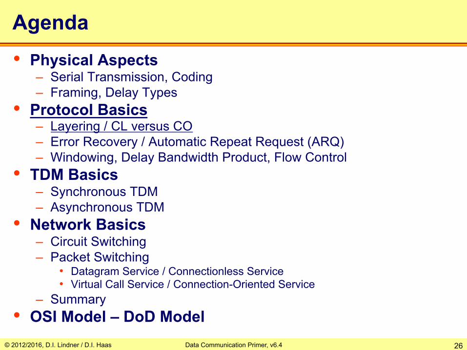
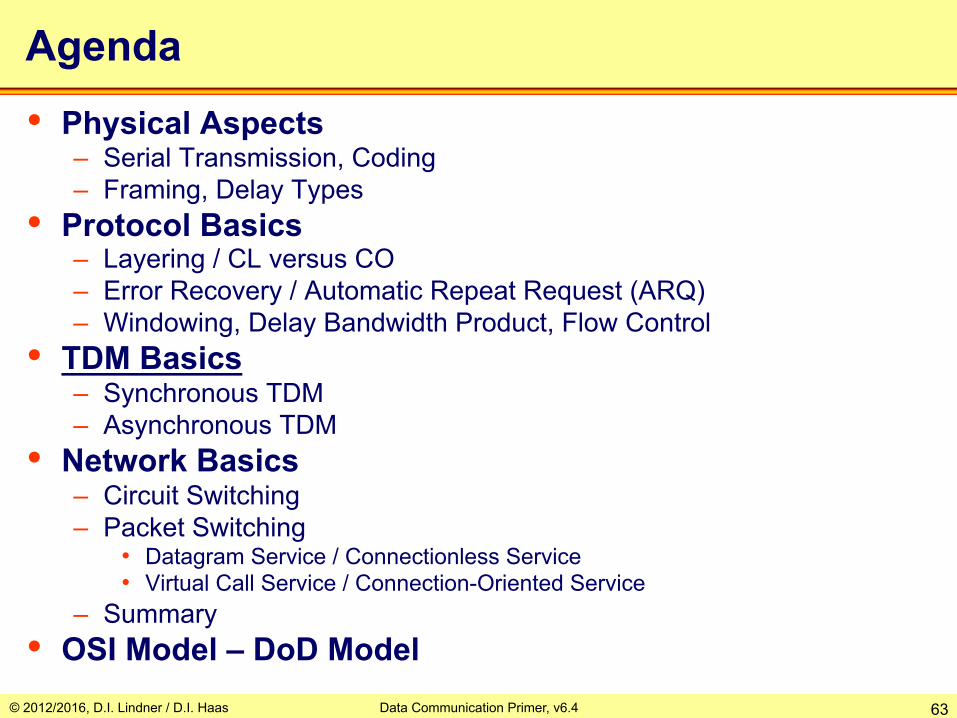
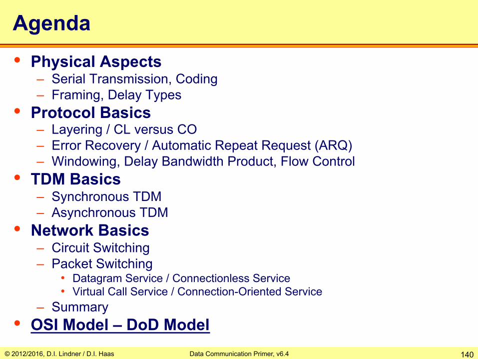
Agenda • Physical Aspects
– Serialization, Coding – Framing, Delay Types
• Protocol Basics – Layering / CL versus CO – Error Recovery / Automatic Repeat Request (ARQ) – Windowing, Delay-Bandwidth Product, Flow Control
• TDM Basics – Synchronous TDM – Asynchronous TDM
• Network Basics – Circuit Switching – Packet Switching
• Datagram Service / Connectionless Service • Virtual Call Service / Connection-Oriented Service
– Summary • OSI Model – DoD Model

© 2012/2016, D.I. Lindner / D.I. Haas Data Communication Primer, v6.4 8
Representation of Symbols for Information Processing, Storage and Exchange • In the context of computer systems and data
communication • Discrete levels = "Digital"
– Resistant against noise
• How many levels? – Binary (easiest)
• Bit (binary digit), values 0 and 1
– M-ary: More information per time unit!
Binary M-ary (here 4 levels, e. g. ISDN)

© 2012/2016, D.I. Lindner / D.I. Haas Data Communication Primer, v6.4 9
1 0 1 1 0 0 1
Source
1
0
1
1
2
n
signal reference
. . . Destination
1
2
n
. . . Bus
Source
1
Destination
1
time
1-bit
clk clk sampling pulse
Transmission of Information: Parallel versus Serial
signal reference
signal reference signal reference
© 2012/2016, D.I. Lindner / D.I. Haas Data Communication Primer, v6.4 10
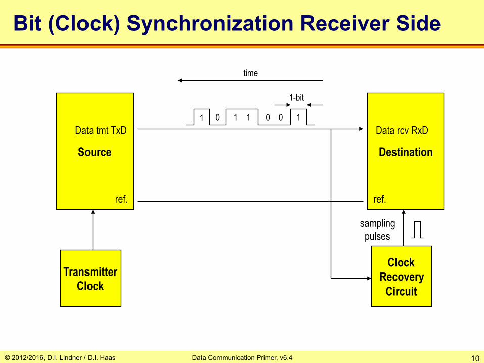
1 0 1 1 0 0 1
Source
ref.
Destination
ref.
time
1-bit
Bit (Clock) Synchronization Receiver Side
Transmitter Clock
Clock Recovery
Circuit
Data tmt TxD Data rcv RxD
sampling pulses

© 2012/2016, D.I. Lindner / D.I. Haas Data Communication Primer, v6.4 11
Line Coding Examples
1 0 1 0 1 1 0 0 1 1 1 1 1 1 1 1 1 1 0 0 0 0 0 0 0 NRZ
RZ
Manchester
Differential Manchester
NRZI
AMI
HDB3
Code Violation

© 2012/2016, D.I. Lindner / D.I. Haas Data Communication Primer, v6.4 12
That Happens To A Signal !!!
Transmitted Signal
Attenuation
Limited Bandwidth Fc
Delay Distortion
Line Noise
Received Signal
0 1 0 0 1 0
0 1 0 1 1 0 Bit Error
Sampling Impulse
time

© 2012/2016, D.I. Lindner / D.I. Haas Data Communication Primer, v6.4 13
Requirements & Facts Serial Transmission System • Information between systems is exchanged in
blocks of bits – Every block is carried in as so called transmission frames
• The recognition of the beginning and the end of a block in the received bit stream is necessary – Frame synchronization
• Errors on physical lines may lead to damage of digital information – 0 becomes 1 and vice versa – The longer the block the higher the probability for an error
• Methods necessary for error checking – Frame protection – Error detection and recovery

© 2012/2016, D.I. Lindner / D.I. Haas Data Communication Primer, v6.4 14
Agenda • Physical Aspects
– Serialization, Coding – Framing, Delay Types
• Protocol Basics – Layering / CL versus CO – Error Recovery / Automatic Repeat Request (ARQ) – Windowing, Delay Bandwidth Product, Flow Control
• TDM Basics – Synchronous TDM – Asynchronous TDM
• Network Basics – Circuit Switching – Packet Switching
• Datagram Service / Connectionless Service • Virtual Call Service / Connection-Oriented Service
– Summary • OSI Model – DoD Model

© 2012/2016, D.I. Lindner / D.I. Haas Data Communication Primer, v6.4 15
SYNC - Sync Pattern ED - Ending Delimiter SD - Starting Delimiter FCS - Frame Check Sequence
payload
frame header bit
synchronization
control information (protocol header)
checksum frame synchronization
Generic Frame Format
frame trailer
DATA Control FCS ED SD Preamble / SYNC
© 2012/2016, D.I. Lindner / D.I. Haas Data Communication Primer, v6.4 16
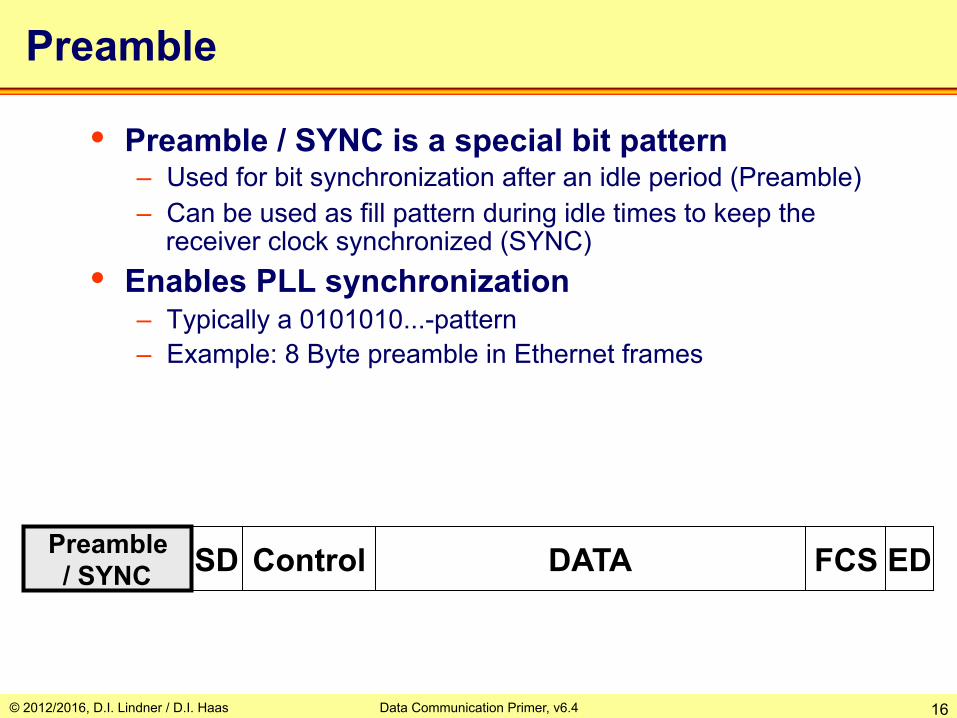
Preamble
DATA Control FCS ED SD Preamble / SYNC
• Preamble / SYNC is a special bit pattern – Used for bit synchronization after an idle period (Preamble) – Can be used as fill pattern during idle times to keep the
receiver clock synchronized (SYNC) • Enables PLL synchronization
– Typically a 0101010...-pattern – Example: 8 Byte preamble in Ethernet frames

© 2012/2016, D.I. Lindner / D.I. Haas Data Communication Primer, v6.4 17
Control Field
• Is used for implementing protocol procedures • Contains information such as
– Frame type, protocol type • Data, Ack, Nack, Connect, Disconnect, Reset, etc. • IP, IPX, AppleTalk, etc.
– Sequence numbers for identification of frame sequence • Necessary for error recovery and flow control with connection
oriented services
– Address information of source and destination in case of a multipoint line
– Frame length, etc.
DATA Control ED SD SYNC FCS

© 2012/2016, D.I. Lindner / D.I. Haas Data Communication Primer, v6.4 18
Frame Synchronization
DATA Control FCS ED SD Preamble
• Beginning and ending of a frame is indicated by SD and ED symbols – Bit-patterns or code-violations – Length-field can replace ED (802.3) – Idle-line can replace ED (Ethernet)
• Also called "Framing"
Starting Delimiter
Ending Delimiter

© 2012/2016, D.I. Lindner / D.I. Haas Data Communication Primer, v6.4 19
Error Control
• Focus on error detection – Include enough redundant information with each block of
date to enable receiver to detect only errors occurred -> error detecting codes -> Frame Check Sequence
– After error detection a retransmission of frame is initiated through protocol feedback to the sender
• Area of ARQ-techniques • Feedback Error Control
DATA Control ED SD SYNC FCS
Protected

© 2012/2016, D.I. Lindner / D.I. Haas Data Communication Primer, v6.4 20
Frame Protection
• A frame check sequence (FCS) protects the integrity of our frame – From Sunspots, Mobile-Phones, Noise, Heisenberg and others
• FCS is calculated upon data bits – Different methods based on mathematical efforts: Parity, Checksum,
CRC
• Receiver compares its own calculation with FCS
DATA Control ED SD Preamble FCS
Protected

© 2012/2016, D.I. Lindner / D.I. Haas Data Communication Primer, v6.4 21
Error Control
• Focus on error correction – Include enough redundant information with to enable
receiver to correct errors occurred -> error correcting codes ECC (important -> “Hamming Distance”)
– Forward Error Control (FEC) – Required for "extreme" conditions
• High BER (Bit Error Rate), EMR • Long delays, space links
– Examples: Reed-Solomon codes, Hamming-codes
DATA Control ED SD SYNC
Protected by encoding using ECC codewords
© 2012/2016, D.I. Lindner / D.I. Haas Data Communication Primer, v6.4 22
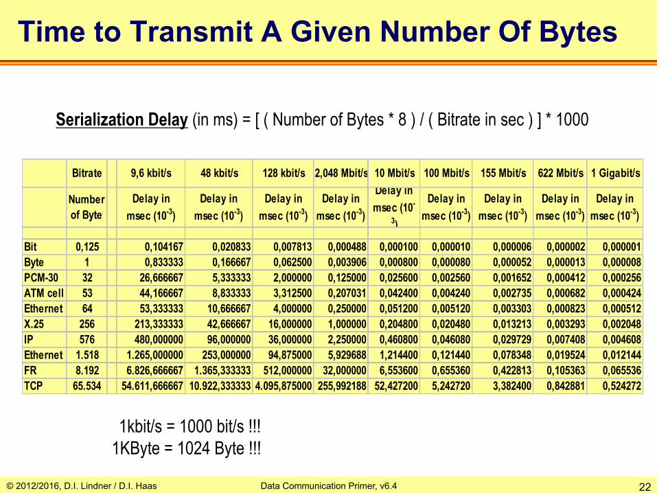
Time to Transmit A Given Number Of Bytes
Bitrate 9,6 kbit/s 48 kbit/s 128 kbit/s 2,048 Mbit/s 10 Mbit/s 100 Mbit/s 155 Mbit/s 622 Mbit/s 1 Gigabit/s
Number of Byte
Delay inmsec (10-3)
Delay inmsec (10-3)
Delay inmsec (10-3)
Delay inmsec (10-3)
Delay inmsec (10-
3)
Delay inmsec (10-3)
Delay inmsec (10-3)
Delay inmsec (10-3)
Delay inmsec (10-3)
Bit 0,125 0,104167 0,020833 0,007813 0,000488 0,000100 0,000010 0,000006 0,000002 0,000001Byte 1 0,833333 0,166667 0,062500 0,003906 0,000800 0,000080 0,000052 0,000013 0,000008PCM-30 32 26,666667 5,333333 2,000000 0,125000 0,025600 0,002560 0,001652 0,000412 0,000256ATM cell 53 44,166667 8,833333 3,312500 0,207031 0,042400 0,004240 0,002735 0,000682 0,000424Ethernet 64 53,333333 10,666667 4,000000 0,250000 0,051200 0,005120 0,003303 0,000823 0,000512X.25 256 213,333333 42,666667 16,000000 1,000000 0,204800 0,020480 0,013213 0,003293 0,002048IP 576 480,000000 96,000000 36,000000 2,250000 0,460800 0,046080 0,029729 0,007408 0,004608Ethernet 1.518 1.265,000000 253,000000 94,875000 5,929688 1,214400 0,121440 0,078348 0,019524 0,012144FR 8.192 6.826,666667 1.365,333333 512,000000 32,000000 6,553600 0,655360 0,422813 0,105363 0,065536TCP 65.534 54.611,666667 10.922,333333 4.095,875000 255,992188 52,427200 5,242720 3,382400 0,842881 0,524272
1kbit/s = 1000 bit/s !!! 1KByte = 1024 Byte !!!
Serialization Delay (in ms) = [ ( Number of Bytes * 8 ) / ( Bitrate in sec ) ] * 1000

© 2012/2016, D.I. Lindner / D.I. Haas Data Communication Primer, v6.4 23
Propagation (Signal) Delay
Tp = Propagation Delay (in ms) = [ ( Distance in m ) / ( velocity in m/sec ) ] * 1000
Total Delay (for a block of bits) = Propagation Delay + Serialization Delay + (Switching Delay)
Distance Delay inmsec (10-3)
Delay inmsec (10-3)
CPU Bus 10 cm 0,0000005 0,00000031 m 0,0000050 0,0000033
RS232, V24/V.28 15 m 0,0000750 0,0000500LAN, Copper, RJ45 100 m 0,0005000 0,0003333LAN, FO, X.21/V.11-V.10 1 km 0,0050000 0,0033333Local Subscriber Line 2,5 km 0,0125000 0,0083333WAN Link Repeater 10 km 0,0500000 0,0333333WAN Link Repeater 100 km 0,5000000 0,3333333WAN FO Link Repeater 1.000 km 5,0000000 3,3333333WAN FO Link Repeater 10.000 km 50,0000000 33,3333333Satellite Link 40.000 km 200,0000000 133,3333333Satellite Link 50.000 km 250,0000000 166,6666667
100.000 km 500,0000000 333,3333333300.000 km 1500,0000000 1000,0000000
v=200.000km/s v=300.000km/s
© 2012/2016, D.I. Lindner / D.I. Haas Data Communication Primer, v6.4 24
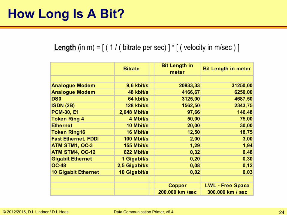
How Long Is A Bit?
Bitrate Bit Length in meter Bit Length in meter
Analogue Modem 9,6 kbit/s 20833,33 31250,00Analogue Modem 48 kbit/s 4166,67 6250,00DS0 64 kbit/s 3125,00 4687,50ISDN (2B) 128 kbit/s 1562,50 2343,75PCM-30, E1 2,048 Mbit/s 97,66 146,48Token Ring 4 4 Mbit/s 50,00 75,00Ethernet 10 Mbit/s 20,00 30,00Token Ring16 16 Mbit/s 12,50 18,75Fast Ethernet, FDDI 100 Mbit/s 2,00 3,00ATM STM1, OC-3 155 Mbit/s 1,29 1,94ATM STM4, OC-12 622 Mbit/s 0,32 0,48Gigabit Ethernet 1 Gigabit/s 0,20 0,30OC-48 2,5 Gigabit/s 0,08 0,1210 Gigabit Ethernet 10 Gigabit/s 0,02 0,03
Copper LWL - Free Space200.000 km /sec 300.000 km / sec
Length (in m) = [ ( 1 / ( bitrate per sec) ] * [ ( velocity in m/sec ) ]
© 2012/2016, D.I. Lindner / D.I. Haas Data Communication Primer, v6.4 25
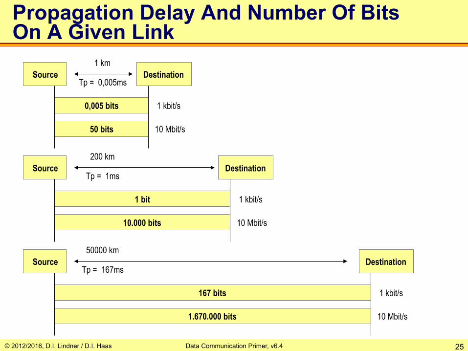
Propagation Delay And Number Of Bits On A Given Link
Source
0,005 bits
50 bits
Destination
1 kbit/s
10 Mbit/s
1 km
Tp = 0,005ms
Source
1 bit
10.000 bits
Destination
1 kbit/s
10 Mbit/s
200 km
Tp = 1ms
Source
167 bits
1.670.000 bits
Destination
1 kbit/s
10 Mbit/s
50000 km
Tp = 167ms
© 2012/2016, D.I. Lindner / D.I. Haas Data Communication Primer, v6.4 26
Agenda • Physical Aspects
– Serial Transmission, Coding – Framing, Delay Types
• Protocol Basics – Layering / CL versus CO – Error Recovery / Automatic Repeat Request (ARQ) – Windowing, Delay Bandwidth Product, Flow Control
• TDM Basics – Synchronous TDM – Asynchronous TDM
• Network Basics – Circuit Switching – Packet Switching
• Datagram Service / Connectionless Service • Virtual Call Service / Connection-Oriented Service
– Summary • OSI Model – DoD Model
© 2012/2016, D.I. Lindner / D.I. Haas Data Communication Primer, v6.4 27
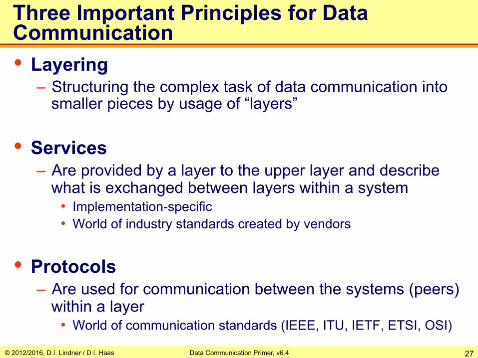
Three Important Principles for Data Communication • Layering
– Structuring the complex task of data communication into smaller pieces by usage of “layers”
• Services – Are provided by a layer to the upper layer and describe
what is exchanged between layers within a system • Implementation-specific • World of industry standards created by vendors
• Protocols – Are used for communication between the systems (peers)
within a layer • World of communication standards (IEEE, ITU, IETF, ETSI, OSI)

© 2012/2016, D.I. Lindner / D.I. Haas Data Communication Primer, v6.4 28
application software
communication software
communication hardware
OS
application software
communication software
communication hardware
OS
Tmt_A Rcv_B
Rcv_A Tmt_B
signal reference
line protocol
Computer A Computer B
Point-to-Point Communication 3 Layer Model
logical relationship between peers
physical wires for transmit and receive

© 2012/2016, D.I. Lindner / D.I. Haas Data Communication Primer, v6.4 29
Best-Effort Service: Connection-less Protocol
time time
Datagram's
Station A Station B
transmission of data
Datagram's
like packet or telegram service of a legacy PTT
no error recovery of corrupted frames

© 2012/2016, D.I. Lindner / D.I. Haas Data Communication Primer, v6.4 30
Reliable Service: Connection-oriented Protocol
time time
Connection Request
Connection Acknowledgement
DATA
Disconnection Request
Disconnected Acknowledgment
Station A Station B
connection establishment
transmission of data
clearing of connection
like Telco telephone call
error recovery of corrupted frames is possible by usage of ARQ techniques
© 2012/2016, D.I. Lindner / D.I. Haas Data Communication Primer, v6.4 31
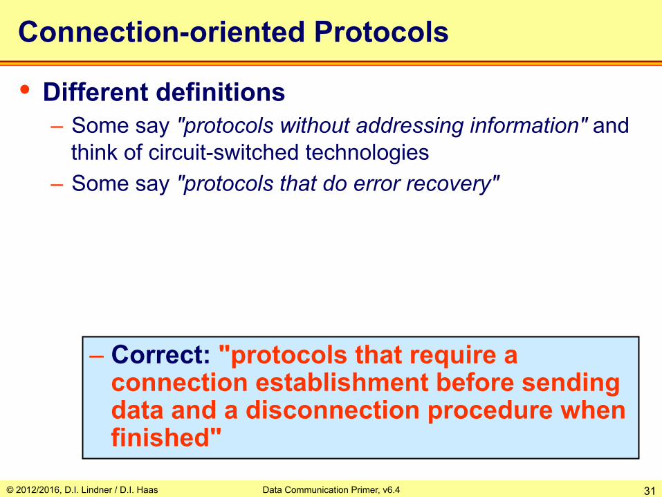
Connection-oriented Protocols
• Different definitions – Some say "protocols without addressing information" and
think of circuit-switched technologies – Some say "protocols that do error recovery"
– Correct: "protocols that require a connection establishment before sending data and a disconnection procedure when finished"

© 2012/2016, D.I. Lindner / D.I. Haas Data Communication Primer, v6.4 32
Agenda • Physical Aspects
– Serial Transmission, Coding – Framing, Delay Types
• Protocol Basics – Layering / CL versus CO – Error Recovery / Automatic Repeat Request (ARQ) – Windowing, Delay Bandwidth Product, Flow Control
• TDM Basics – Synchronous TDM – Asynchronous TDM
• Network Basics – Circuit Switching – Packet Switching
• Datagram Service / Connectionless Service • Virtual Call Service / Connection-Oriented Service
– Summary • OSI Model – DoD Model
© 2012/2016, D.I. Lindner / D.I. Haas Data Communication Primer, v6.4 33
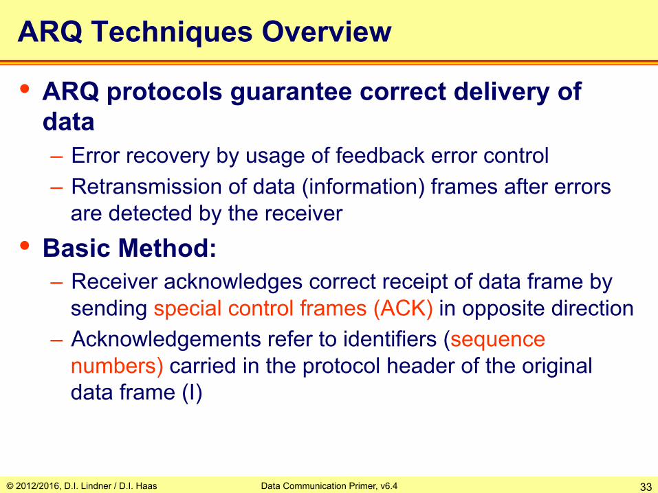
ARQ Techniques Overview
• ARQ protocols guarantee correct delivery of data – Error recovery by usage of feedback error control – Retransmission of data (information) frames after errors
are detected by the receiver • Basic Method:
– Receiver acknowledges correct receipt of data frame by sending special control frames (ACK) in opposite direction
– Acknowledgements refer to identifiers (sequence numbers) carried in the protocol header of the original data frame (I)

© 2012/2016, D.I. Lindner / D.I. Haas Data Communication Primer, v6.4 34
application software
communication software
communication hardware
OS
application software
communication software
communication hardware
OS
Tmt_A Rcv_B
Rcv_A Tmt_B
signal reference
Computer A Computer B
Com-SW Layer Implementation Necessary Resource Elements
Protocol State Machine Retransmission List Receive List Timers Control Variables Queues / Mailboxes for operating API

© 2012/2016, D.I. Lindner / D.I. Haas Data Communication Primer, v6.4 35
application software
communication software
communication hardware
OS
application software
communication software
communication hardware
OS
Tmt_A Rcv_B
Rcv_A Tmt_B
signal reference
line protocol
Computer A Computer B
Com-SW Layer Implementation Necessary Protocol Elements
Frame (Control Field)Types: Connect request / ack Disconnect request / ack I, ACK, NACK, SREJ Identifiers
© 2012/2016, D.I. Lindner / D.I. Haas Data Communication Primer, v6.4 36
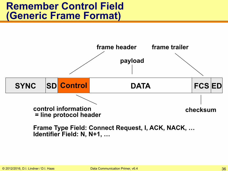
payload
frame header
control information = line protocol header Frame Type Field: Connect Request, I, ACK, NACK, … Identifier Field: N, N+1, …
checksum
Remember Control Field (Generic Frame Format)
frame trailer
DATA Control FCS ED SD SYNC
© 2012/2016, D.I. Lindner / D.I. Haas Data Communication Primer, v6.4 37
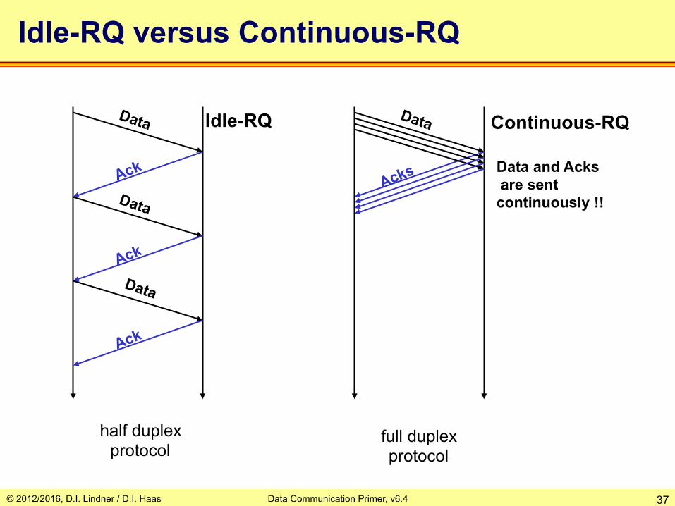
Idle-RQ versus Continuous-RQ
Data and Acks are sent continuously !!
Idle-RQ Continuous-RQ
half duplex protocol
full duplex protocol

© 2012/2016, D.I. Lindner / D.I. Haas Data Communication Primer, v6.4 38
Why Identifiers or Sequence Numbers?
Sender Receiver Data "ABCD"
Ack
Ack
Ack
Data "ABCD"
Data "EFGH"
No Ack? Retransmission!
ABCD
ABCD ABCD
ABCD ABCD EFGH
© 2012/2016, D.I. Lindner / D.I. Haas Data Communication Primer, v6.4 39
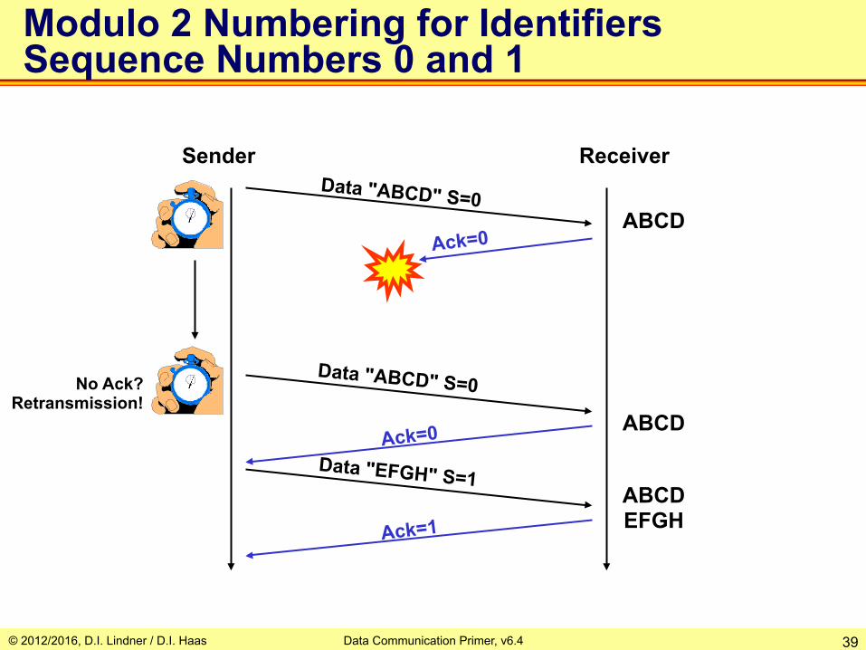
Modulo 2 Numbering for Identifiers Sequence Numbers 0 and 1
Sender Receiver Data "ABCD" S=0
Ack=0
Ack=0
Ack=1
Data "ABCD" S=0
Data "EFGH" S=1
No Ack? Retransmission!
ABCD
ABCD
ABCD EFGH
© 2012/2016, D.I. Lindner / D.I. Haas Data Communication Primer, v6.4 40
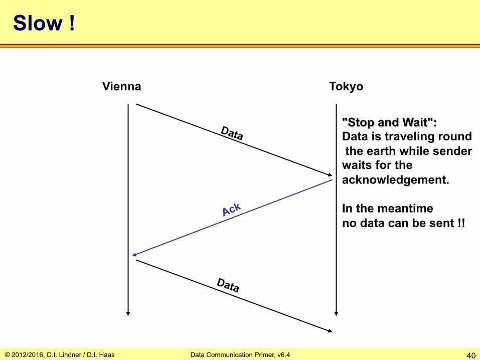
Slow !
Vienna Tokyo
"Stop and Wait": Data is traveling round the earth while sender waits for the acknowledgement. In the meantime no data can be sent !!
© 2012/2016, D.I. Lindner / D.I. Haas Data Communication Primer, v6.4 41
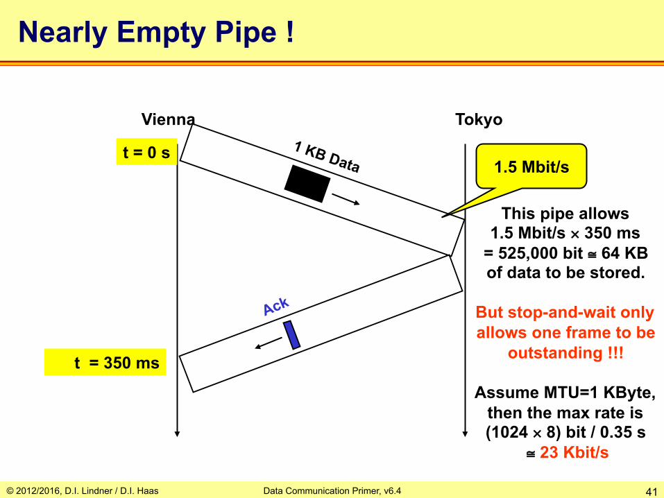
Nearly Empty Pipe !
Vienna Tokyo
t = 0 s
t = 350 ms
1.5 Mbit/s
This pipe allows 1.5 Mbit/s × 350 ms
= 525,000 bit ≅ 64 KB of data to be stored.
But stop-and-wait only allows one frame to be
outstanding !!!
Assume MTU=1 KByte, then the max rate is (1024 × 8) bit / 0.35 s
≅ 23 Kbit/s
© 2012/2016, D.I. Lindner / D.I. Haas Data Communication Primer, v6.4 42
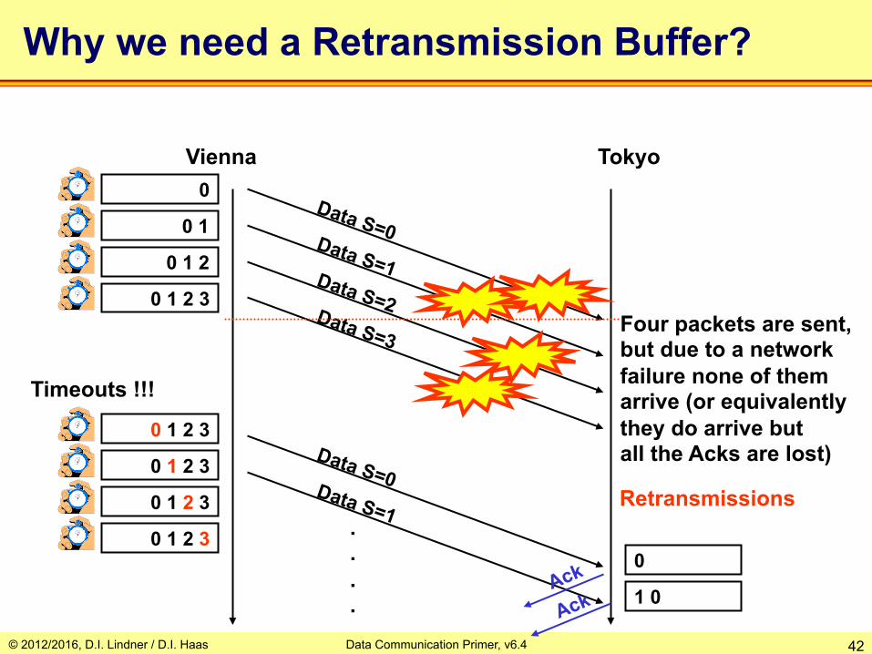
Why we need a Retransmission Buffer?
Vienna Tokyo
Four packets are sent, but due to a network failure none of them arrive (or equivalently they do arrive but all the Acks are lost)
Timeouts !!!
0
0 1
0 1 2
0 1 2 3
.
.
.
.
0 1 2 3
0 1 2 3
0 1 2 3
0 1 2 3
Retransmissions
0
1 0

© 2012/2016, D.I. Lindner / D.I. Haas Data Communication Primer, v6.4 43
Full Pipe !
Vienna Tokyo
t = 0 s
t = 350 ms
1.5 Mbit/s
This situation corresponds with a
sliding window

© 2012/2016, D.I. Lindner / D.I. Haas Data Communication Primer, v6.4 44
ARQ (Automatic Repeat Requests) Variants
Idle-RQ Selective ACK (SACK)
e.g.TCP modern variant GoBackN
e.g. HDLC, LAPB Positive ACK
e.g. TCP base variant Selective Reject (SREJ)
e.g. HDLC variant
Continuous-RQ Used by TFTP
(Trivial File Transfer Protocol) Based on UDP (User Datagram Protocol)
Note: FTP (File Transfer Protocol)
Based on TCP (Transmission Control Protocol)

© 2012/2016, D.I. Lindner / D.I. Haas Data Communication Primer, v6.4 45
Selective Acknowledgement (1) Vienna Tokyo
Data S=0
Data S=1 Ack=0
Ack=2
Ack=3
Data S=2
Data S=3
Data S=1
Ack=1
0
0 1
1 2
1 2 3
Timeout for S=1 1st retransmission
1
1 3
1
0
2 0
3 2 0
1 3 2 0 Reordering necessary
Retransmission Buffer Receive Buffer
© 2012/2016, D.I. Lindner / D.I. Haas Data Communication Primer, v6.4 46
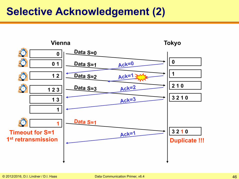
Selective Acknowledgement (2)
Vienna Tokyo Data S=0
Data S=1 Ack=0
Ack=2
Ack=3
Data S=2
Data S=3
Data S=1
Ack=1
0
0 1
1 2
1 2 3
Timeout for S=1 1st retransmission
1
1 3
1
0
2 1 0
3 2 1 0
3 2 1 0 Duplicate !!!
Ack=1 1

© 2012/2016, D.I. Lindner / D.I. Haas Data Communication Primer, v6.4 47
GoBackN with Sequence Numbers
Vienna Tokyo 0 Data S=0
Data S=1 Ack=1
Data S=2
NACK = 1
0 1
1 2
1 2 3
0
0
0
Data S=1 1 0
2 1 0
Data S=2 Ack=2
Ack=4
1 2 3
2 3
1 2 3 Data S=3 0
Data S=3 3 2 1 0 Sequence
maintained !

© 2012/2016, D.I. Lindner / D.I. Haas Data Communication Primer, v6.4 48
Positive ACK with Sequence Numbers
Vienna Tokyo 0 Data S=0
Data S=1 Ack=1
Data S=2
0 1
1 2
0
0
2 0 Data S=3 3 2 0
1 2 3
Timeout S=1
1 2 3 Data S=1 1 3 2 0 Ack=4
Cumulative Ack

© 2012/2016, D.I. Lindner / D.I. Haas Data Communication Primer, v6.4 49
Agenda • Physical Aspects
– Serial Transmission, Coding – Framing, Delay Types
• Protocol Basics – Layering / CL versus CO – Error Recovery / Automatic Repeat Request (ARQ) – Windowing, Delay Bandwidth Product, Flow Control
• TDM Basics – Synchronous TDM – Asynchronous TDM
• Network Basics – Circuit Switching – Packet Switching
• Datagram Service / Connectionless Service • Virtual Call Service / Connection-Oriented Service
– Summary • OSI Model – DoD Model
© 2012/2016, D.I. Lindner / D.I. Haas Data Communication Primer, v6.4 50
Timers - Retransmission Timeout
• The value for retransmission timeouts for line protocols can be easily calculated using the following parameters – Bitrate – Maximum data frame size – Worst case time at receiver to generate an
acknowledgment – Size of acknowledgment frame
• Calculation for network protocols with varying transmission delays is more complex – Adaptive process is necessary

© 2012/2016, D.I. Lindner / D.I. Haas Data Communication Primer, v6.4 51
Send Window and Sliding Window
• Continuous-RQ techniques would require infinite sender/receiver buffer size (also infinite number of identifiers) – If we do not restrict the number of unacknowledged
frames • Send Window W
– Is the maximum allowed number of unacknowledged frames in the retransmission list
• Necessary sender-buffer size is W * maximum frame size – Also called the Window Size
• Handling procedure – Is called (Sliding) Windowing

© 2012/2016, D.I. Lindner / D.I. Haas Data Communication Primer, v6.4 52
Sliding Window Basics (1)
1 2 3 4 5 6 7 8 9 10 11 12
Window W = 5
Sent but not yet acknowledged
Can be sent as soon as
possible
Can't be send until window moves
....
Usable window time
Event t0:

© 2012/2016, D.I. Lindner / D.I. Haas Data Communication Primer, v6.4 53
Sliding Window Basics (2)
1 2 3 4 5 6 7 8 9 10 11 12
Window W = 5
Sent and already acknowledged
Sent but not yet acknowledged
Will send as soon as possible
can't send until window moves
....
Usable window time
Event t1:
© 2012/2016, D.I. Lindner / D.I. Haas Data Communication Primer, v6.4 54
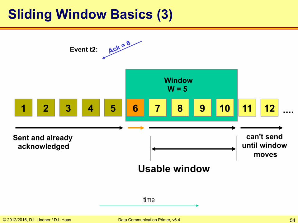
Sliding Window Basics (3)
1 2 3 4 5 6 7 8 9 10 11 12
Window W = 5
....
Usable window
time
Sent and already acknowledged
can't send until window
moves
Event t2:

© 2012/2016, D.I. Lindner / D.I. Haas Data Communication Primer, v6.4 55
Windowing with Numbering Modulo W+1
1 2 3 4 5 0 1 2 3 4 5 0
Window W = 5
Sent and already acknowledged
Sent but not yet acknowledged
Will send as soon as possible
can't send until window moves
....
Usable window time
GoBackN and send-window W means W+1 Identifier and numbering with modulo W+1
© 2012/2016, D.I. Lindner / D.I. Haas Data Communication Primer, v6.4 56
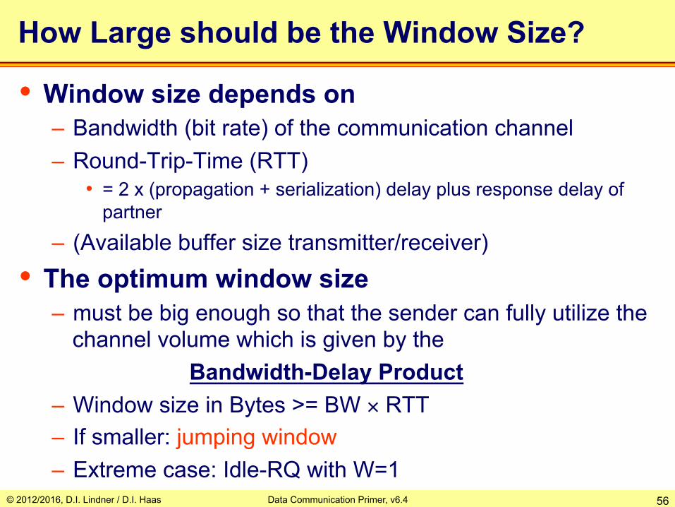
How Large should be the Window Size?
• Window size depends on – Bandwidth (bit rate) of the communication channel – Round-Trip-Time (RTT)
• = 2 x (propagation + serialization) delay plus response delay of partner
– (Available buffer size transmitter/receiver)
• The optimum window size – must be big enough so that the sender can fully utilize the
channel volume which is given by the Bandwidth-Delay Product – Window size in Bytes >= BW × RTT – If smaller: jumping window – Extreme case: Idle-RQ with W=1

© 2012/2016, D.I. Lindner / D.I. Haas Data Communication Primer, v6.4 57
Vienna Tokyo
t = 0 s
t = 350 ms
1.5 Mbit/s
This situation corresponds with a true sliding window
Full Pipe with Continuous-RQ and W = 64
This pipe allows 1.5 Mbit/s × 350 ms
= 525,000 bit ≅ 64 KB of data.
Continuous-RQ (C-RQ) allows several frames to be outstanding. With 1 KByte maximum Frame Size optimum would be W = 64 !!!
W = 64
© 2012/2016, D.I. Lindner / D.I. Haas Data Communication Primer, v6.4 58
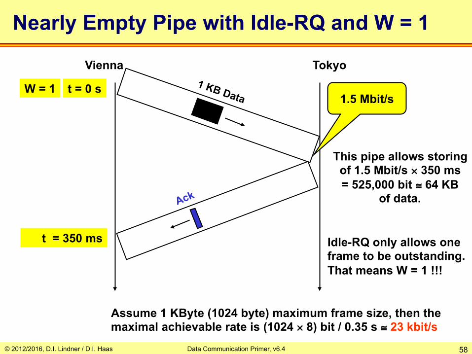
Nearly Empty Pipe with Idle-RQ and W = 1
Vienna Tokyo
t = 0 s
t = 350 ms
1.5 Mbit/s
This pipe allows storing of 1.5 Mbit/s × 350 ms = 525,000 bit ≅ 64 KB
of data.
Assume 1 KByte (1024 byte) maximum frame size, then the maximal achievable rate is (1024 × 8) bit / 0.35 s ≅ 23 kbit/s
Idle-RQ only allows one frame to be outstanding. That means W = 1 !!!
W = 1
© 2012/2016, D.I. Lindner / D.I. Haas Data Communication Primer, v6.4 59
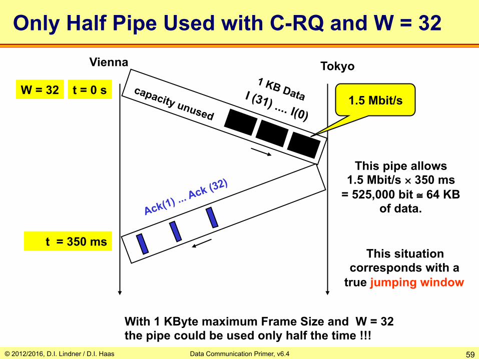
Vienna Tokyo
t = 0 s
t = 350 ms
1.5 Mbit/s
This situation corresponds with a
true jumping window
Only Half Pipe Used with C-RQ and W = 32
This pipe allows 1.5 Mbit/s × 350 ms
= 525,000 bit ≅ 64 KB of data.
With 1 KByte maximum Frame Size and W = 32 the pipe could be used only half the time !!!
W = 32
© 2012/2016, D.I. Lindner / D.I. Haas Data Communication Primer, v6.4 60
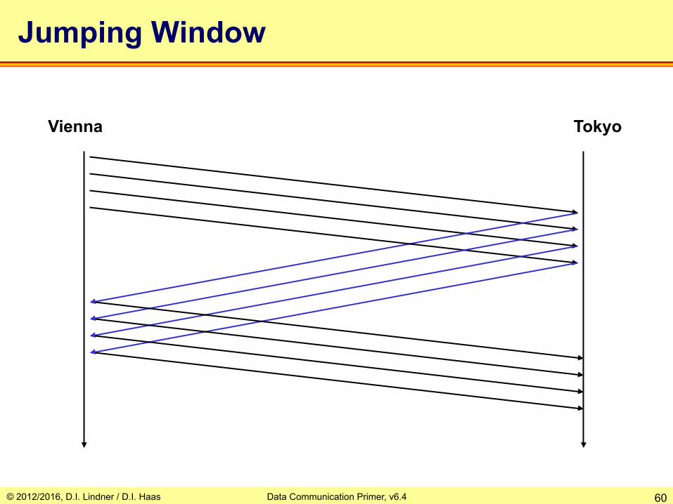
Jumping Window
Vienna Tokyo

© 2012/2016, D.I. Lindner / D.I. Haas Data Communication Primer, v6.4 61
application software
communication software
communication hardware
OS
application software
communication software
communication hardware
OS
Tmt_A Rcv_B
Rcv_A Tmt_B
signal reference
flow control indicating congestion
Host A Host B
Flow Control

© 2012/2016, D.I. Lindner / D.I. Haas Data Communication Primer, v6.4 62
Flow Control: Adaptive Windowing
• Window size could be – Constant or dynamic during lifetime of a connection
• Constant window size is used e.g. by HDLC, X.25
• If window size is dynamic – A start value is negotiated during connection
establishment – Actual window size will be dynamically adjusted to an
optimal value • Receiver continuously advertises optimal value (e.g. based
on availability of free buffer memory) • Advertised window size = 0 -> STOP • Advertised window size > 0 -> GO
– Adaptive windowing (e.g used by TCP)
© 2012/2016, D.I. Lindner / D.I. Haas Data Communication Primer, v6.4 63
Agenda • Physical Aspects
– Serial Transmission, Coding – Framing, Delay Types
• Protocol Basics – Layering / CL versus CO – Error Recovery / Automatic Repeat Request (ARQ) – Windowing, Delay Bandwidth Product, Flow Control
• TDM Basics – Synchronous TDM – Asynchronous TDM
• Network Basics – Circuit Switching – Packet Switching
• Datagram Service / Connectionless Service • Virtual Call Service / Connection-Oriented Service
– Summary • OSI Model – DoD Model
© 2012/2016, D.I. Lindner / D.I. Haas Data Communication Primer, v6.4 64
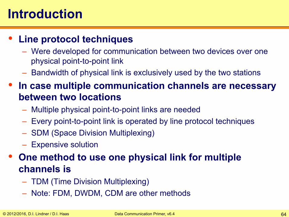
Introduction
• Line protocol techniques – Were developed for communication between two devices over one
physical point-to-point link – Bandwidth of physical link is exclusively used by the two stations
• In case multiple communication channels are necessary between two locations – Multiple physical point-to-point links are needed – Every point-to-point link is operated by line protocol techniques – SDM (Space Division Multiplexing) – Expensive solution
• One method to use one physical link for multiple channels is – TDM (Time Division Multiplexing) – Note: FDM, DWDM, CDM are other methods
© 2012/2016, D.I. Lindner / D.I. Haas Data Communication Primer, v6.4 65
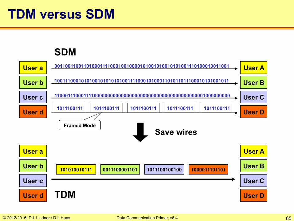
TDM versus SDM
00110011001101000111100010010000101001010010101001110100010011001
10011100010101001010101010011110001010001101011011100010101001011
11000111000111100000000000000000000000000000000000000001000000000
101010010111
User A
User B
User C
User D
0011100001101 1011100100100 1000011101101
SDM
User A
User B
User C
User D
1011100111 1011100111 1011100111 1011100111 1011100111
Framed Mode Save wires
User a
User b
User c
User d
User a
User b
User c
User d TDM

© 2012/2016, D.I. Lindner / D.I. Haas Data Communication Primer, v6.4 66
TDM Multiplexing / Demultiplexing
• TDM multiplexer – Take a number of input channels and - by interleaving them - output
them as one data stream on one physical trunk line – Demultiplexer does the opposite
A1
B1
C1
D1
A2
B2
C2
D2
Mux
DeMux Trunk Line
Ports Ports
Direction of Transmission
P1 P2
P3 P4
P1 P2
P3
P4
T T

© 2012/2016, D.I. Lindner / D.I. Haas Data Communication Primer, v6.4 67
Types of TDM
• Depending on timing behavior two basic TDM methods – Synchronous (deterministic) TDM
• Timeslots have constant length (capacity) and can be used in a synchronous, periodical manner
• Examples: PDH (E1, T1), SDH (STM-1, STM-4)
– Asynchronous (statistical) TDM • Timeslots have variable length and are used on demand
(depending on the statistics of the individual channel communication)
• Examples: Ethernet, WLAN

© 2012/2016, D.I. Lindner / D.I. Haas Data Communication Primer, v6.4 68
Agenda • Physical Aspects
– Serial Transmission, Coding – Framing, Delay Types
• Protocol Basics – Layering / CL versus CO – Error Recovery / Automatic Repeat Request (ARQ) – Windowing, Delay Bandwidth Product, Flow Control
• TDM Basics – Synchronous TDM – Asynchronous TDM
• Network Basics – Circuit Switching – Packet Switching
• Datagram Service / Connectionless Service • Virtual Call Service / Connection-Oriented Service
– Summary • OSI Model – DoD Model

Synchronous TDM (1)
C A
User A2
User B2
User C2
User D2
A B C D
User A1
User B1
User C1
User D1
A B C D A B C D D
A
B
C
D
A
B
C
D
Flag
Timeslot
Frame
Trunk- Link
De-Mux Mux
Access-Links User Ports
Periodic frames consisting of a constant number of timeslots Every channel occupies a dedicated timeslot Implicit addressing given by the position of a timeslot in the frame Trunk rate = number of timeslots x access-link rate Each channel experiences constant delay and no delay variation (jitter)
4 × 64 kbit/s + F ≅ 256 kbit/s
64 kbit/s
64 kbit/s
64 kbit/s
64 kbit/s
Direction of transmission
© 2012/2016, D.I. Lindner / D.I. Haas 69 Data Communication Primer, v6.4
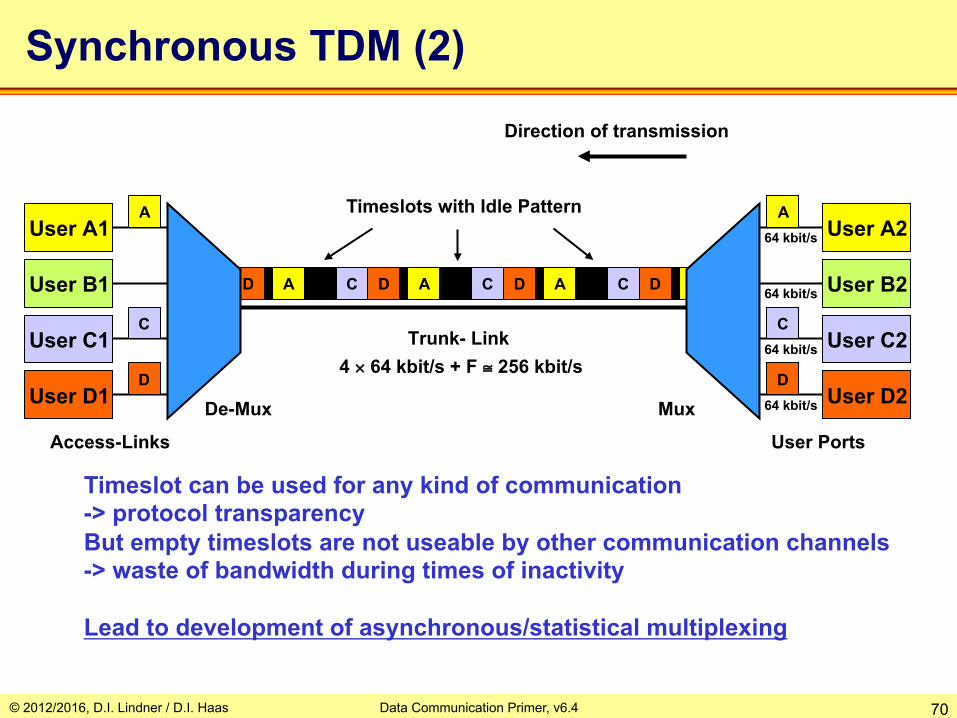
Synchronous TDM (2)
C A
User A2
User B2
User C2
User D2
A C D
User A1
User B1
User C1
User D1
A C D A C D D
A
C
D
A
C
D
Trunk- Link
De-Mux Mux
Access-Links User Ports
Timeslot can be used for any kind of communication -> protocol transparency But empty timeslots are not useable by other communication channels -> waste of bandwidth during times of inactivity Lead to development of asynchronous/statistical multiplexing
4 × 64 kbit/s + F ≅ 256 kbit/s
64 kbit/s
64 kbit/s
64 kbit/s
64 kbit/s
Direction of transmission
Timeslots with Idle Pattern
© 2012/2016, D.I. Lindner / D.I. Haas 70 Data Communication Primer, v6.4

© 2012/2016, D.I. Lindner / D.I. Haas Data Communication Primer, v6.4 71
Agenda • Physical Aspects
– Serial Transmission, Coding – Framing, Delay Types
• Protocol Basics – Layering / CL versus CO – Error Recovery / Automatic Repeat Request (ARQ) – Windowing, Delay Bandwidth Product, Flow Control
• TDM Basics – Synchronous TDM – Asynchronous TDM
• Network Basics – Circuit Switching – Packet Switching
• Datagram Service / Connectionless Service • Virtual Call Service / Connection-Oriented Service
– Summary • OSI Model – DoD Model

Asynchronous TDM (1)
Trunk rate is dimensioned for average usage in statistical manner Each user channels can send packets whenever he/she wants Frames have different lengths Buffering is necessary if trunk is already occupied by another channel Explicit addressing by usage of address fields in the frame Not protocol-transparent any more
User A2
User B2
User C2
User D2
User A1
User B1
User C1
User D1
A (A2->A1) B C D (D2->D1)
A
C
D
B
C
D
A C C
D
Direction of transmission
128 kbit/s
64 kbit/s
64 kbit/s
64 kbit/s
64 kbit/s
Trunk- Link
De-Mux with buffers
Mux with buffers
Access-Links Access-Links
Average data rates ≅ 32 kbit/s Address Fields
Src & Dst
Frame 1 Frame 2
© 2012/2016, D.I. Lindner / D.I. Haas 72 Data Communication Primer, v6.4

Asynchronous TDM (2)
If other channels are silent, one channel can fully utilize his/her access rate -> better usage of network bandwidth Variable delay and variable delay variation (jitter) Buffer overflow leads to loss of packets
Direction of transmission
Access-Links Access-Links
User A2
User B2
User C2
User D2
User A1
User B1
User C1
User D1
D (A2->A1) B D (D2->D1) D (D2->D1)
D
A
128 kbit/s
128 kbit/s
128 kbit/s
128 kbit/s
128 kbit/s
Trunk- Link
D
© 2012/2016, D.I. Lindner / D.I. Haas 73 Data Communication Primer, v6.4

© 2012/2016, D.I. Lindner / D.I. Haas Data Communication Primer, v6.4 74
Agenda • Physical Aspects
– Serial Transmission, Coding – Framing, Delay Types
• Protocol Basics – Layering / CL versus CO – Error Recovery / Automatic Repeat Request (ARQ) – Windowing, Delay Bandwidth Product, Flow Control
• TDM Basics – Synchronous TDM – Asynchronous TDM
• Network Basics – Circuit Switching – Packet Switching
• Datagram Service / Connectionless Service • Virtual Call Service / Connection-Oriented Service
– Summary • OSI Model – DoD Model
© 2012/2016, D.I. Lindner / D.I. Haas Data Communication Primer, v6.4 75
User B
User C
User D
User E
User F
User A
?
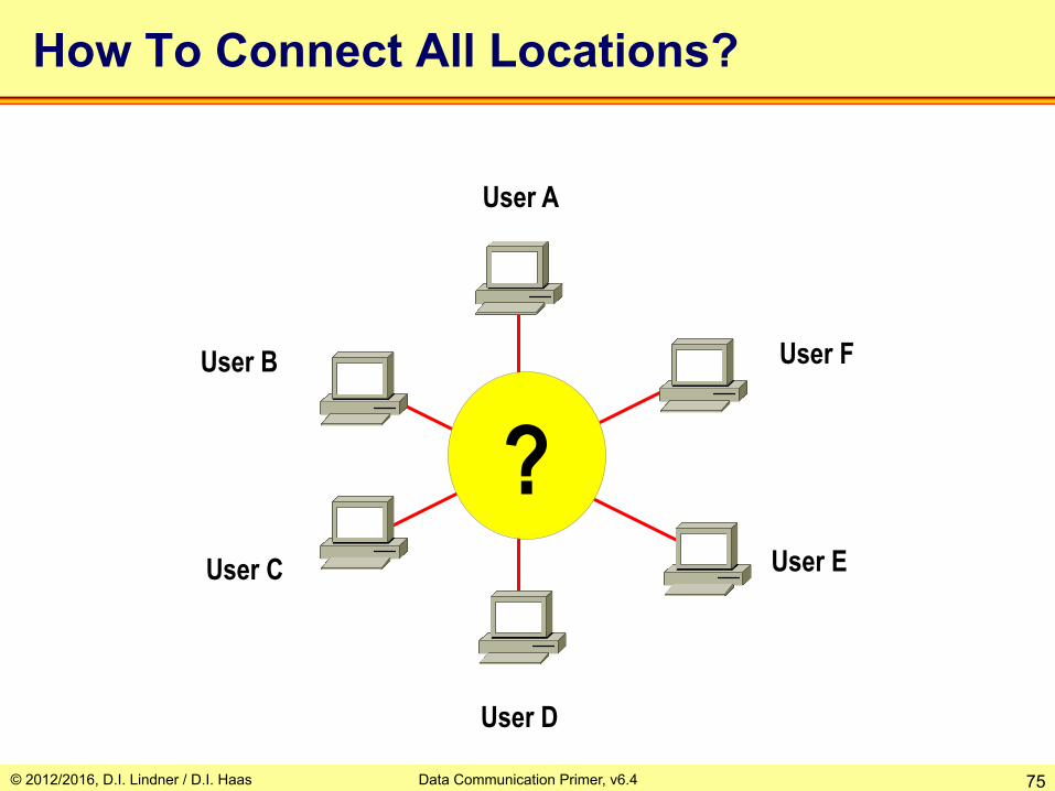
How To Connect All Locations?

© 2012/2016, D.I. Lindner / D.I. Haas Data Communication Primer, v6.4 76
Networking: Fully Meshed
User A
User B
User C
User D
User F
User E
• Metcalfe's Law: n(n-1)/2 links
• Good fault tolerance
• Expensive

© 2012/2016, D.I. Lindner / D.I. Haas Data Communication Primer, v6.4 77
Networking: Switching
User A
User B
User C
User D
User F
User E
Network switches could be based on: Synchronous TDM
• Circuit Switching
or Asynchronous TDM
• Packet Switching
© 2012/2016, D.I. Lindner / D.I. Haas Data Communication Primer, v6.4 78
Agenda • Physical Aspects
– Serial Transmission, Coding – Framing, Delay Types
• Protocol Basics – Layering / CL versus CO – Error Recovery / Automatic Repeat Request (ARQ) – Windowing, Delay Bandwidth Product, Flow Control
• TDM Basics – Synchronous TDM – Asynchronous TDM
• Network Basics – Circuit Switching – Packet Switching
• Datagram Service / Connectionless Service • Virtual Call Service / Connection-Oriented Service
– Summary • OSI Model – DoD Model

© 2012/2016, D.I. Lindner / D.I. Haas Data Communication Primer, v6.4 79
PA1 PA5
PB1
PB5
PC1 PC5
PD1
PD5
PE1
PE5
PF1 PF5
T1
T2
T2
T3 T3
T4
T4
T1
A
B
C
D
E
F
1
3 4
2
P - access line, T - trunk line
Circuit Switching
TDM-Switch
e.g. E1 f-PDH framing used on all trunk lines T# given us 30 channels a 64kbit/s per trunk line
e.g. 64kbit/s per access port PX#

© 2012/2016, D.I. Lindner / D.I. Haas Data Communication Primer, v6.4 80
PA1 -> T2 (1) : A1-B1 PA2 -> T2 (2) : A2-C1 PA3 -> T2 (3) : A3-D1 PA4 -> T1 (1) : A4- F1 PA5 -> T1 (2) : A5-E1
T1 (1) -> PF1 T1 (2) -> PE1
T3 (1) -> PD1 T2 (1) -> PB1 T2 (2) -> PC1 T2 (3) -> T3 (1)
timeslot identifier
PA1 PA5
PB1
PB5
PC1 PC5
PD1
PD5
PE1
PE5
PF1 PF5
A
B
C
D
E
F circuit switching table switch 1
Connections of Device A
T1
T2
T2
T3 T3
T4
T4
T1
P - access line, T - trunk line
1
3 4
2

© 2012/2016, D.I. Lindner / D.I. Haas Data Communication Primer, v6.4 81
PA1 -> T2 (1) : A1-B1 PA2 -> T2 (2) : A2-C1 PA3 -> T2 (3) : A3-D1 PA4 -> T1 (1) : A4- F1 PA5 -> T1 (2) : A5-E1
T1 (1) -> PF1 T1 (2) -> PE1
T3 (1) -> PD1 T2 (1) -> PB1 T2 (2) -> PC1 T2 (3) -> T3 (1)
timeslot identifier
PA1 PA5
PB1
PB5
PC1 PC5
PD1
PD5
PE1
PE5
PF1 PF5
A
B
C
D
E
F circuit switching table switch 1
Connections of Device A Circuit Path PA3 (A) - PD1 (D)
T1
T2
T2
T3 T3
T4
T4
T1
P - access line, T - trunk line
1
3 4
2
© 2012/2016, D.I. Lindner / D.I. Haas Data Communication Primer, v6.4 82
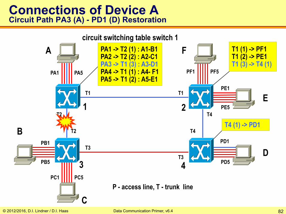
PA1 -> T2 (1) : A1-B1 PA2 -> T2 (2) : A2-C1 PA3 -> T1 (3) : A3-D1 PA4 -> T1 (1) : A4- F1 PA5 -> T1 (2) : A5-E1
T1 (1) -> PF1 T1 (2) -> PE1 T1 (3) -> T4 (1)
T4 (1) -> PD1
PA1 PA5
PB1
PB5
PC1 PC5
PD1
PD5
PE1
PE5
PF1 PF5
A
B
C
D
E
F circuit switching table switch 1
Connections of Device A Circuit Path PA3 (A) - PD1 (D) Restoration
T1
T2
T2
T3 T3
T4
T4
T1
P - access line, T - trunk line
1
3 4
2

© 2012/2016, D.I. Lindner / D.I. Haas Data Communication Primer, v6.4 83
TA (1) -> T2 (1) : A1-B1 TA (2) -> T2 (2) : A2-C1 TA (3) -> T2 (3) : A3-D1 TA (4) -> T1 (1) : A4-F1 TA (5) -> T1 (2) : A5-E1
T1 (1) -> TF (1) T1 (2) -> TE (1)
T3 (1) -> TD (1) T2 (1) -> TB (1) T2 (2) -> TC (1) T2 (3) -> T3 (1)
timeslot identifier
TA
TB
TC
TD
TE
TF
A
B
C
D
E
F
TA, TB, ... TF use TDM technique
TDM lines to Devices
switching table switch 1
T1
T2
T2
T3 T3
T4
T4
T1
1
3 4
2

© 2012/2016, D.I. Lindner / D.I. Haas Data Communication Primer, v6.4 84
Circuit Switching – Facts
• Based on synchronous (deterministic) TDM – Minimal and constant delay – Protocol transparent – High bit rate on trunk lines
• Sum of access links traversing a given trunk – Possibly bad utilization
• Idle pattern in timeslots if no data present – Good for isochronous traffic (voice)
• Switching table entries – Static (manually configured) – Dynamic (signaling protocol) – Scales with number of connections!

© 2012/2016, D.I. Lindner / D.I. Haas Data Communication Primer, v6.4 85
Circuit Switching Data Networks
• Network providers offer permanent circuit services – With permanent entries in circuit switching tables – Optional with fast automatic switchover (50ms) in case of trunk failure – Leased line
• Network providers offer switched circuit services – With dynamic entries in circuit switching tables generated on demand – Today implementations are based on ISDN only – Integrated Services Digital Network – Outband signaling (via D-channel) between ISDN end system (ISDN-
TE) and ISDN-LE (Local Exchange) = that is the local TDM switch – Communication between ISDN-LEs is based on Signaling System 7
(SS7)
• Base is PDH or SDH transmission infrastructure

© 2012/2016, D.I. Lindner / D.I. Haas Data Communication Primer, v6.4 86
ISDN User-to-Network Interface (UNI)
ISDN-TE
ISDN Network Service
physical access link (I.430, I.431)
ISDN-LE
channel for user data (B-channel)
channel for signaling (D-channel)
(Q.921, Q.931)
…
logical channels multiplexed on physical channel
TE … Terminal Equipment (ISDN end system) LE … Local Exchange (ISDN switch)

© 2012/2016, D.I. Lindner / D.I. Haas Data Communication Primer, v6.4 87
Call Setup on D channel via Q.931
Data or Voice Transfer on B channel
Call Release on D channel via Q.931
Usage D-Channel vs. Bearer Channel
ISDN-TE Local ISDN-LE
ISDN-TE
Remote ISDN-TE
ISDN-TE Local ISDN-LE

© 2012/2016, D.I. Lindner / D.I. Haas Data Communication Primer, v6.4 88
Basic Rate Interface (BRI)
– 2 B (bearer) channels with 64 kbit/s each • carrying digitized voice or data
– 1 D (data) channel with 16 kbit/s • for outband signaling purposes (e.g. Q.931 protocol)
– 2 B and D are synchronous TDM-multiplexed on physical access line
BRI
2 × B
D
Telco Network
144 kbit/s (plus overhead)
ISDN-TE ISDN-LE
UNI (BRI)

© 2012/2016, D.I. Lindner / D.I. Haas Data Communication Primer, v6.4 89
Primary Rate Interface (PRI)
– 30 B (Bearer) channels with 64 kbit/s each (USA 23 B) – 1 D (Data) channel with 64 kbit/s
• for signaling purposes (e.g. Q.931 protocol)
– 30 B and D are synchronous TDM-multiplexed on one physical access line
30 × B
D
PRI 2.048 Mbit/s (E1 Frames)
ISDN-TE ISDN-LE UNI (BRI)

© 2012/2016, D.I. Lindner / D.I. Haas Data Communication Primer, v6.4 90
ISDN Big Picture (AIN, SS7)
STP
STP STP
STP
STP STP
SCP SCP
SP … Signalling Point STP … Signal Transfer Point SCP … Service Control Point CST … Circuit Switching Table TC … Transit Center LE … Local Exchange AIN … Advanced Intelligent Network
CST
CST CST
CST
ISDN-LE
ISDN-LE ISDN-LE
ISDN-LE
ISDN-TC
ISDN-TC
voice trunk (PDH, SDH)
outband signalling path (SS7)
Synchronous TDM Switch
SP
SP
SP
SP
SP
SP

© 2012/2016, D.I. Lindner / D.I. Haas Data Communication Primer, v6.4 91
Agenda • Physical Aspects
– Serial Transmission, Coding – Framing, Delay Types
• Protocol Basics – Layering / CL versus CO – Error Recovery / Automatic Repeat Request (ARQ) – Windowing, Delay Bandwidth Product, Flow Control
• TDM Basics – Synchronous TDM – Asynchronous TDM
• Network Basics – Circuit Switching – Packet Switching
• Datagram Service / Connectionless Service • Virtual Call Service / Connection-Oriented Service
– Summary • OSI Model – DoD Model

© 2012/2016, D.I. Lindner / D.I. Haas Data Communication Primer, v6.4 92
A
D C
B 1
2 3 4
5 6
PA
T1
T1
T1 T2
T4
T2
PD
T3
T1 T2
PC
T3
T4 T2
T1
T2
PB
Packet Switching Topology
Unique Network Address Asynchronous
TDM
Buffers
Common Language
Flow Control
Trunk Lines
Access Line
© 2012/2016, D.I. Lindner / D.I. Haas Data Communication Primer, v6.4 93
A
D C
B 1
2 3 4
5 6
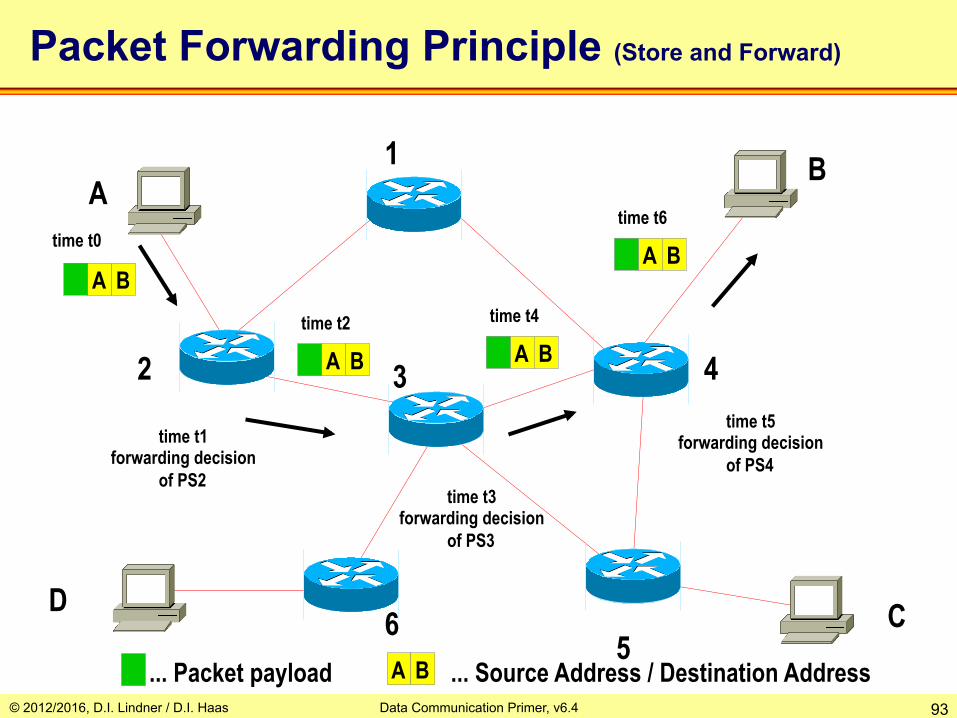
Packet Forwarding Principle (Store and Forward)
A B
... Packet payload
A B A B
A B time t0
time t2 time t4
time t6
time t1 forwarding decision
of PS2 time t3
forwarding decision of PS3
time t5 forwarding decision
of PS4
A B ... Source Address / Destination Address
© 2012/2016, D.I. Lindner / D.I. Haas Data Communication Primer, v6.4 94
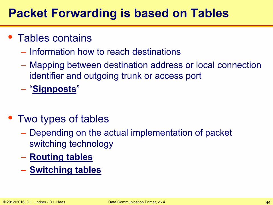
Packet Forwarding is based on Tables
• Tables contains – Information how to reach destinations – Mapping between destination address or local connection
identifier and outgoing trunk or access port – “Signposts”
• Two types of tables – Depending on the actual implementation of packet
switching technology – Routing tables – Switching tables
© 2012/2016, D.I. Lindner / D.I. Haas Data Communication Primer, v6.4 95
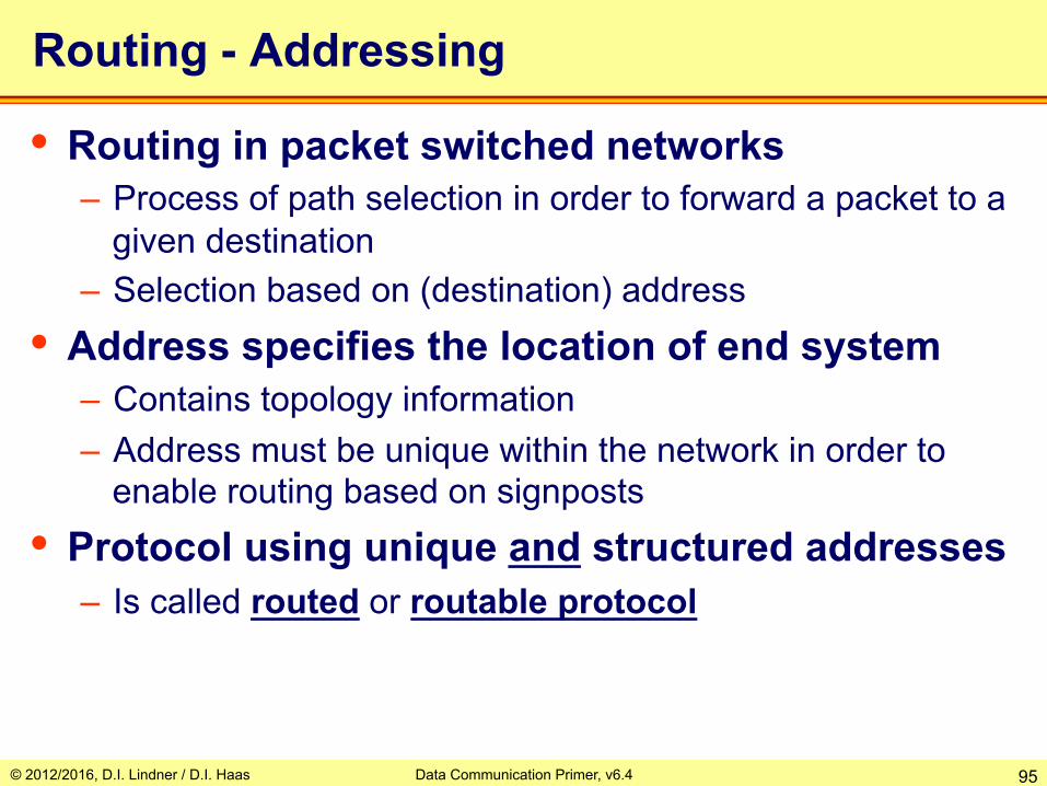
Routing - Addressing
• Routing in packet switched networks – Process of path selection in order to forward a packet to a
given destination – Selection based on (destination) address
• Address specifies the location of end system – Contains topology information – Address must be unique within the network in order to
enable routing based on signposts • Protocol using unique and structured addresses
– Is called routed or routable protocol
© 2012/2016, D.I. Lindner / D.I. Haas Data Communication Primer, v6.4 96
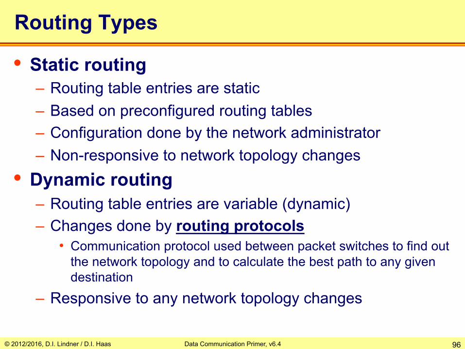
Routing Types
• Static routing – Routing table entries are static – Based on preconfigured routing tables – Configuration done by the network administrator – Non-responsive to network topology changes
• Dynamic routing – Routing table entries are variable (dynamic) – Changes done by routing protocols
• Communication protocol used between packet switches to find out the network topology and to calculate the best path to any given destination
– Responsive to any network topology changes

© 2012/2016, D.I. Lindner / D.I. Haas Data Communication Primer, v6.4 97
Routing Table Usage / Type of Service
• Routing tables are differently used – Depending on the type of service of the packet switching
network • Packet switched networks based on
– Connectionless Service (CL) - Datagram service • Routing tables are used to forward all kind of packets
– Connection-oriented Service (CO) – Virtual Call service • Routing tables are used to forward control packets for connection
establishment • These control packets generate entries in switching tables • After connection establishment, only the switching tables are used
to forward data packets

© 2012/2016, D.I. Lindner / D.I. Haas Data Communication Primer, v6.4 98
Technology Differences - Summary
• Datagram Principle – Global and routable addresses – Connectionless – Routing table for forwarding of packets
• Virtual Call Principle – Local addresses – Connection-oriented – Routing table for setup of connections – Switching table for forwarding of packets

© 2012/2016, D.I. Lindner / D.I. Haas Data Communication Primer, v6.4 99
Agenda • Physical Aspects
– Serial Transmission, Coding – Framing, Delay Types
• Protocol Basics – Layering / CL versus CO – Error Recovery / Automatic Repeat Request (ARQ) – Windowing, Delay Bandwidth Product, Flow Control
• TDM Basics – Synchronous TDM – Asynchronous TDM
• Network Basics – Circuit Switching – Packet Switching
• Datagram Service / Connectionless Service • Virtual Call Service / Connection-Oriented Service
– Summary • OSI Model – DoD Model

© 2012/2016, D.I. Lindner / D.I. Haas Data Communication Primer, v6.4 100
Datagram Service Principles
• Connectionless service – Packets can be sent without establishing a logical
connection between end systems in advance – Packets have no sequence numbers – They are called “Datagrams”
• Every incoming datagram – Is processed independently regarding to all other
datagrams by the packet switches • The forwarding decision for incoming packets
– Depends on the current state of the routing table • Each packet contains
– Complete address information (source and destination)

© 2012/2016, D.I. Lindner / D.I. Haas Data Communication Primer, v6.4 101
A
D C
B 1
2 3 4
5 6
Packet forwarding (CL) is based on routing tables only (Datagram Service, Best-Effort Service)
B PS3 C PS3 D PS3
to next hop B local C PS5 D PS3
to next hop
B PS4 C PS5 D PS6
to next hop
source address
A B
destination address
... payload
A B A B
A B

© 2012/2016, D.I. Lindner / D.I. Haas Data Communication Primer, v6.4 102
A C A B
A C A B
D B A B
D B A B
D B
D B
A C
A C
A
D
B 1
2 3 4
5 6
Datagrams are forwarded completely independent from each other based on current state of routing tables
© 2012/2016, D.I. Lindner / D.I. Haas Data Communication Primer, v6.4 103
A C A B
A C A B
D B A B
D B
D B
D B
A C
A
D C
B 1
2 3 4
5 6
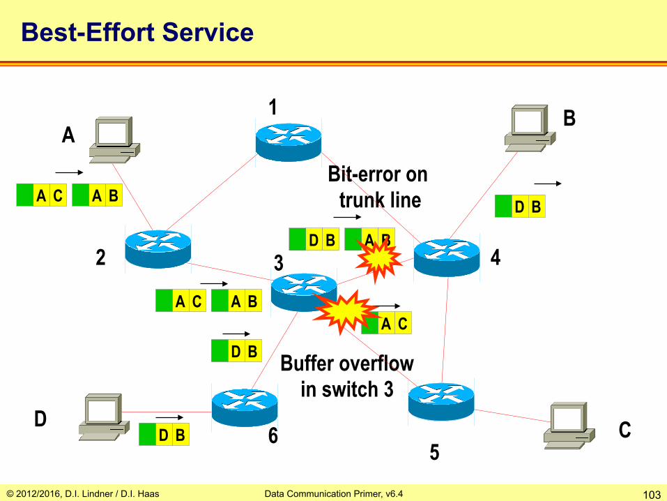
Best-Effort Service
Bit-error on trunk line
Buffer overflow in switch 3
© 2012/2016, D.I. Lindner / D.I. Haas Data Communication Primer, v6.4 104
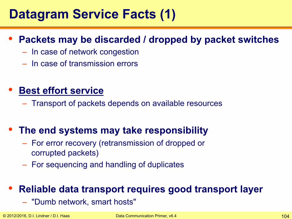
Datagram Service Facts (1)
• Packets may be discarded / dropped by packet switches – In case of network congestion – In case of transmission errors
• Best effort service – Transport of packets depends on available resources
• The end systems may take responsibility – For error recovery (retransmission of dropped or
corrupted packets) – For sequencing and handling of duplicates
• Reliable data transport requires good transport layer – "Dumb network, smart hosts"

© 2012/2016, D.I. Lindner / D.I. Haas Data Communication Primer, v6.4 105
A B A B
A B
A B A B
A
D C
B 1
2 3 4
5 6
Rerouting – Sequencing Not Guaranteed !
A B A B
D B
A B D B
D B
D B
Rerouting

© 2012/2016, D.I. Lindner / D.I. Haas Data Communication Primer, v6.4 106
Datagram Service Facts (2)
• Rerouting in case of topology changes or load balancing means – Packets with the same address information can take
different paths to destination – Packets may arrive out of sequence
• Sequence not guaranteed – Rerouting on topology change – Load sharing on redundant paths – End stations must care
© 2012/2016, D.I. Lindner / D.I. Haas Data Communication Primer, v6.4 107
A
D C
B
2 3
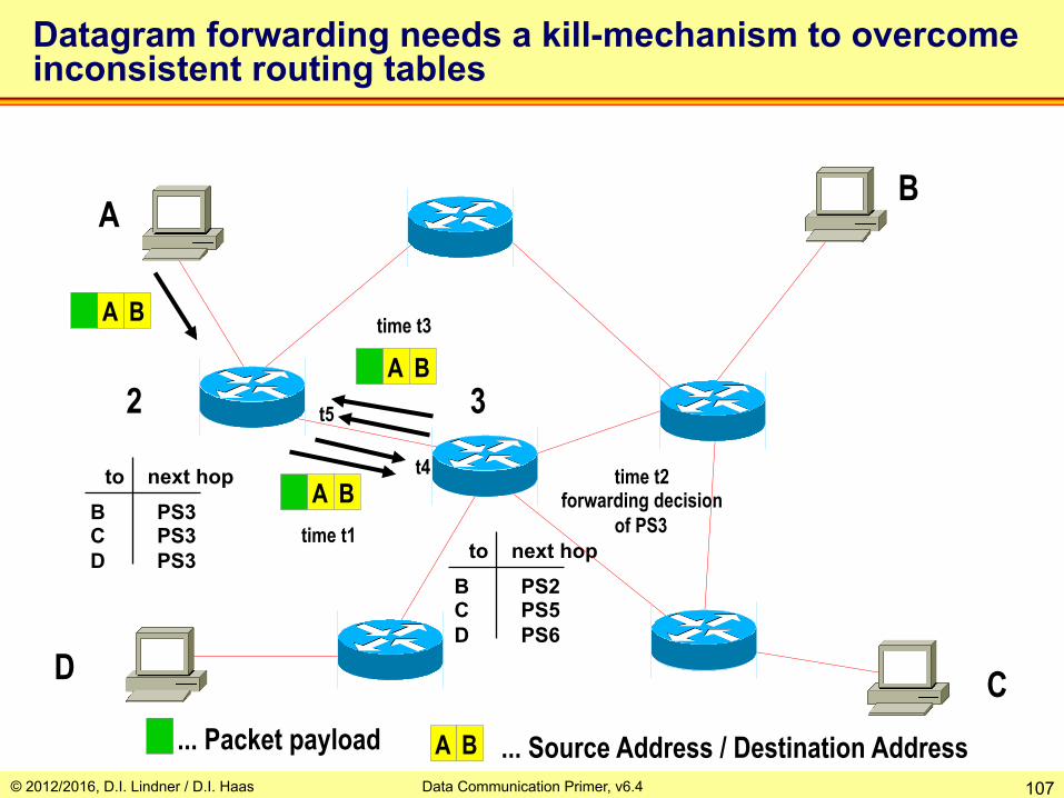
Datagram forwarding needs a kill-mechanism to overcome inconsistent routing tables
A B
... Packet payload
A B
A B
time t1
time t2 forwarding decision
of PS3
A B ... Source Address / Destination Address
B PS2 C PS5 D PS6
to next hop
B PS3 C PS3 D PS3
to next hop
time t3
t4
t5

© 2012/2016, D.I. Lindner / D.I. Haas Data Communication Primer, v6.4 108
Datagram Service Facts (3)
• Connectionless behavior – Faster delivery of first data
– No resource reservation is possible • e.g. bandwidth on trunk line for a certain communication between
end systems • e.g. buffer memory on packet switches
– Bad “Quality of Service” (QoS)
– Flow control between packet-switch and end-system • Would help in case of congestion if proactively performed • But lack of trust makes it impossible to implement it
© 2012/2016, D.I. Lindner / D.I. Haas Data Communication Primer, v6.4 109
Datagram Service Facts (4)
• Advantages – Small protocol overhead (easy to implement in end
systems and packet switches) – Fastest delivery of data between end systems because no
connection must be established in advance • Disadvantage
– Delivery of packets is not guaranteed by the network, must be handled by end systems using higher layer protocol
– Proactive flow control between end-system and packet switch is not possible

© 2012/2016, D.I. Lindner / D.I. Haas Data Communication Primer, v6.4 110
Network Technologies based on Datagram Method • IP
– Packet is called IP datagram – End system is called IP host – Packet switch is called IP router
• IPX (Novell) • XNS • Appletalk • Decnet Phase IV • OSI CNLP

© 2012/2016, D.I. Lindner / D.I. Haas Data Communication Primer, v6.4 111
Agenda • Physical Aspects
– Serial Transmission, Coding – Framing, Delay Types
• Protocol Basics – Layering / CL versus CO – Error Recovery / Automatic Repeat Request (ARQ) – Windowing, Delay Bandwidth Product, Flow Control
• TDM Basics – Synchronous TDM – Asynchronous TDM
• Network Basics – Circuit Switching – Packet Switching
• Datagram Service / Connectionless Service • Virtual Call Service / Connection-Oriented Service
– Summary • OSI Model – DoD Model

© 2012/2016, D.I. Lindner / D.I. Haas Data Communication Primer, v6.4 112
Virtual Call Principles
• Connection-oriented service – Special control packets (call setup packets) establish a
logical (virtual) point-to-point connection between end systems first
– We call that connection a Virtual Circuit – After connection is established
• Data packets can be transmitted across that virtual circuit • Typically virtual circuit will be closed after data transfer is finished
• Different methods are possible – To establish a virtual call service

© 2012/2016, D.I. Lindner / D.I. Haas Data Communication Primer, v6.4 113
14 CR A B
A
E C
B 1
2 3 4
5 6
CR ... Call Request
Packet forwarding (CO) is based on special switching tables but call-setup still uses conventional routing tables (Virtual Call Setup 1)
A :14
from to
from to
from to B PS3 C PS3 E PS3
to next hop
Switching Table of PS 4
unique addresses
local connection identifier
packet type

© 2012/2016, D.I. Lindner / D.I. Haas Data Communication Primer, v6.4 114
23 CR A B
A
E C
B 1
2 3 4
5 6
CR ... Call Request
14
Virtual Call Setup 2
A :14 3:23
from to
2 :23
from to from to
B PS4 C PS5 E PS6
to next hop

© 2012/2016, D.I. Lindner / D.I. Haas Data Communication Primer, v6.4 115
A
E C
B 1
2 3 4
5 6
CR ... Call Request
14
07 CR A B
23
Virtual Call Setup 3
3:07
from to
A :14 3:23
from to
2 :23 4:07
from to
B local C PS5 E PS3
to next hop

© 2012/2016, D.I. Lindner / D.I. Haas Data Communication Primer, v6.4 116
44 CR A B
A
E C
B 1
2 3 4
5 6
CR ... Call Request
14
23
07
Virtual connection A - B: 14-23-07-44
Virtual Call Setup 4
A :14 3:23
from to
3:07 B:44
from to
2 :23 4:07
from to

© 2012/2016, D.I. Lindner / D.I. Haas Data Communication Primer, v6.4 117 CA ... Call Accepted
A B CA 44
A
E C
B 1
2 3 4
5 6
14
23
07
Virtual connection A - B: 14-23-07-44
44
Virtual Call Setup 5
A :14 3:23
to from
3:07 B:44
to from
2 :23 4:07
to from

© 2012/2016, D.I. Lindner / D.I. Haas Data Communication Primer, v6.4 118 CA ... Call Accepted
A
E C
B 1
2 3 4
5 6
14
23
07
Virtual connection A - B: 14-23-07-44
44 A B CA 14
Virtual Call Setup 6
A :14 3:23
to from
3:07 B:44
to from
2 :23 4:07
to from

© 2012/2016, D.I. Lindner / D.I. Haas Data Communication Primer, v6.4 119
A
E C
B 1
2 3 4
5 6
14
23
07
Virtual connection A - B: 14-23-07-44
44 D 14
D ... Data Packet … payload
Data Forwarding 1
A :14 3:23
from to
3:07 B:44
from to
2 :23 4:07
from to
© 2012/2016, D.I. Lindner / D.I. Haas Data Communication Primer, v6.4 120
A
E C
B 1
2 3 4
5 6
14
23
07
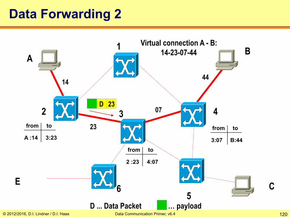
Virtual connection A - B: 14-23-07-44
44
D 23
D ... Data Packet … payload
Data Forwarding 2
A :14 3:23
from to
3:07 B:44
from to
2 :23 4:07
from to
© 2012/2016, D.I. Lindner / D.I. Haas Data Communication Primer, v6.4 121
A
E C
B 1
2 3 4
5 6
14
23
07
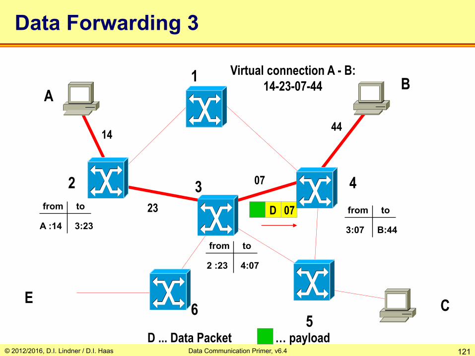
Virtual connection A - B: 14-23-07-44
44
D 07
D ... Data Packet … payload
Data Forwarding 3
A :14 3:23
from to
3:07 B:44
from to
2 :23 4:07
from to
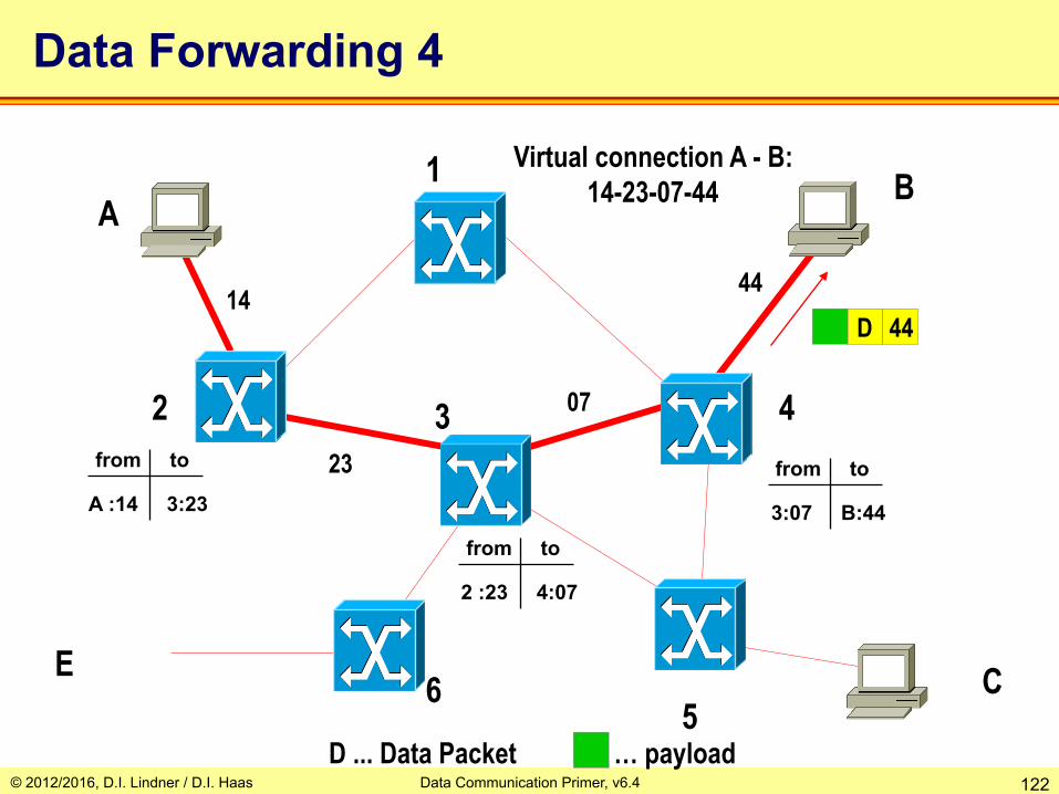
© 2012/2016, D.I. Lindner / D.I. Haas Data Communication Primer, v6.4 122
A
E C
B 1
2 3 4
5 6
14
23
07
Virtual connection A - B: 14-23-07-44
44 D 44
D ... Data Packet … payload
Data Forwarding 4
A :14 3:23
from to
3:07 B:44
from to
2 :23 4:07
from to
© 2012/2016, D.I. Lindner / D.I. Haas Data Communication Primer, v6.4 123
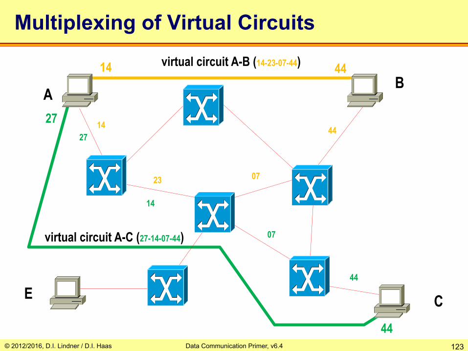
A
E C
B 14
14
07
virtual circuit A-B (14-23-07-44) 44
27
23
07
44
virtual circuit A-C (27-14-07-44)
Multiplexing of Virtual Circuits
44
44
14 27
© 2012/2016, D.I. Lindner / D.I. Haas Data Communication Primer, v6.4 124
Virtual Call Service Facts (1)
• The sequence of data packets is guaranteed by the network – Packets can use the established path only
• Path selection is done during connection setup – Afterwards, entries of routing table are not used
• In case of trunk line or packet switch failure – Virtual circuits will be closed and must be reestablished
again by end systems using call setup packets – If there is at least one redundant path, packet switches
can establish a new virtual circuit taking the redundant path

© 2012/2016, D.I. Lindner / D.I. Haas Data Communication Primer, v6.4 125
Example
BANG

© 2012/2016, D.I. Lindner / D.I. Haas Data Communication Primer, v6.4 126
Virtual Call Service Facts (2)
• Connection-oriented packet switching – Allows flow control procedures between end system and
packet switch because of connection-oriented approach • In connectionless packet switching networks flow control is not
possible or only poorly implemented
– Flow control procedures can avoid buffer overflow and hence network congestion
– Allows reservation of resources • Capacity, buffers, cpu time, etc.
– Can offer Quality of Service (QoS) – Call setup can be denied by network if QoS can not be
guaranteed

© 2012/2016, D.I. Lindner / D.I. Haas Data Communication Primer, v6.4 127
Virtual Call Service Facts (3)
• Advantages – Required resources of packet switches can be reserved
during call setup and hence QoS could be provided – End system view of the network
• Reliable point-to-point transport pipe based on network internal error recovery, flow control and sequencing procedures (X.25)
• Higher protocol layers can rely on network services (X.25)
– Readiness for receipt is tested in advance • Call setup of SVC service
• Disadvantages – Call setup takes time – More complex protocols for end systems and packet
switches than datagram service

© 2012/2016, D.I. Lindner / D.I. Haas Data Communication Primer, v6.4 128
Virtual Call – Summary (1)
• Connection establishment – Through routing process (!) – Globally unique topology-related addresses necessary – Creates entries in switching tables – Can reserve switching resources (QoS)
• Packet forwarding relies on local identifiers – Not topology related – Only unique per port – Swapping of local identifiers (labels) according to the
switching table

© 2012/2016, D.I. Lindner / D.I. Haas Data Communication Primer, v6.4 129
Virtual Call – Summary (2)
• Connection can be regarded as virtual pipe – Sequence is guaranteed – Resources can be guaranteed
• Virtual call multiplex – Multiple virtual pipes per switch and interface possible – Pipes are locally distinguished through connection
identifier • Network failures disrupt pipe
– Connection re-establishment necessary – Datagram networks are more robust

© 2012/2016, D.I. Lindner / D.I. Haas Data Communication Primer, v6.4 130
Network Technologies based on Virtual Call Method • X.25
– Reliable transport pipe because of protocol inherent error recovery and flow control
– Local identifier = LCN – In-band signaling
• Frame Relay – Virtual circuit technique but no error recovery – Congestion indication instead of flow control – Local identifier = DLCI – Out-band signaling
• ATM (Asynchronous Transfer Mode) – Same as Frame Relay but packets with fixed length – Hence called cell switching – Local identifier = VPI/VCI – Out-band signaling

© 2012/2016, D.I. Lindner / D.I. Haas Data Communication Primer, v6.4 131
Agenda • Physical Aspects
– Serial Transmission, Coding – Framing, Delay Types
• Protocol Basics – Layering / CL versus CO – Error Recovery / Automatic Repeat Request (ARQ) – Windowing, Delay Bandwidth Product, Flow Control
• TDM Basics – Synchronous TDM – Asynchronous TDM
• Network Basics – Circuit Switching – Packet Switching
• Datagram Service / Connectionless Service • Virtual Call Service / Connection-Oriented Service
– Summary • OSI Model – DoD Model

© 2012/2016, D.I. Lindner / D.I. Haas Data Communication Primer, v6.4 132
Summary
• Only two fundamental network principles – Circuit switching – Packet switching – The first is good for real-time voice (traffic) the latter is
good for data traffic – But everybody wants to have the best of both worlds
• Packet switching allows two basic types: – Datagram (CL) versus Virtual Call (CO) – Different address types (!) for forwarding decision of data
packet • Unique routable address (CL) • Local connection identifier (CO)

© 2012/2016, D.I. Lindner / D.I. Haas Data Communication Primer, v6.4 133
Circuit Switching
T1
T2
T3
TA T2
T3
T1
T4 T4
T4 T4 T1 TB
User A2
User B5
TA(1) → T1(4) : A1-C9 TA(2) → T2(7) : A2-B5 TA(3) → T2(6) : A3-D1
. . . . . .
. . . . . . T2(6) → T4(1)
T2(7) → T3(18) . . . . . .
. . . . . . T3(18) → T4(5) T3(19) → T1(1)
. . . . . .
. . . . . . T4(4) → TB(9) T4(5) → TB(5)
. . . . . .
TA(2) → T2(7) : A2-B5 T2(7) → T3(18)
T3(18) → T4(5)
T4(5) → TB(5)

© 2012/2016, D.I. Lindner / D.I. Haas Data Communication Primer, v6.4 134
Packet Switching
T1
T2
T3
TA T2
T3
T1
T4 T4
T4 T4 T1 TB
User A2
User B5
Address Information
• Each switch must analyze address information
• "Store and Forward“ • Decision about where to
forward is based on tables

Destination Next Hop A local B R2 C R2
..... .....
© 2012/2016, D.I. Lindner / D.I. Haas Data Communication Primer, v6.4 135
IP Datagram Service
User A.2
User B.5
R1 R2
R4
R3
R5
Destination A local B R2 C R2
..... .....
A2 B5
Next Hop
A2 B5
A2 B5
Destination Next Hop A R1 B R4 C R3
..... .....
A2 B
5
Destination Next Hop A R2 B R5 C R2
..... .....
A2 B5
Destination Next Hop A R4 B local C R4
..... ..... IP address (structured address Net-ID:Host-ID)
IP Host IP Router
IP Routing Table of R1
Destination Based Routing

© 2012/2016, D.I. Lindner / D.I. Haas Data Communication Primer, v6.4 136
P1
Virtual Call – Call Request (CR)
P1
P2
P3
P0 P0
P1
P2 P0 P0 P2
User A.2
User B.5
PS1 PS2 PS3
PS4 PS5
44 CR B5 A2
Destination Next Hop A local B PS2 C PS2
..... .....
In Out P0:44 P2:10
P2 P0
10 CR B5 A2
Destination Next Hop A PS1 B PS4 C PS3
..... .....
In Out P0:10 P3:02
Destination Next Hop A PS2 B PS5 C PS2
..... .....
02 C
R
B5
A2
In Out P1:02 P2:69
69 CR B5 A2
Destination Next Hop A PS4 B local C PS4
..... .....
In Out P0:69 P2:19
19 CR B5 A2
Routing Table of PS1
Switching Table of PS1

© 2012/2016, D.I. Lindner / D.I. Haas Data Communication Primer, v6.4 137
P1
Virtual Call – Call Accepted (CA)
P1
P2
P3
P0 P0
P1
P2 P0 P0 P2
User A.2
User B.5
PS1 PS2 PS3
PS4 PS5
P2 P0 In Out P0:10 P3:02
02 CA
B5
A2
19 CA B5 A2
In Out P0:69 P2:19
In Out P1:02 P2:69
69 CA B5 A2
In Out P0:44 P2:10
10 CA B5 A2 44 CA B5 A2
© 2012/2016, D.I. Lindner / D.I. Haas Data Communication Primer, v6.4 138
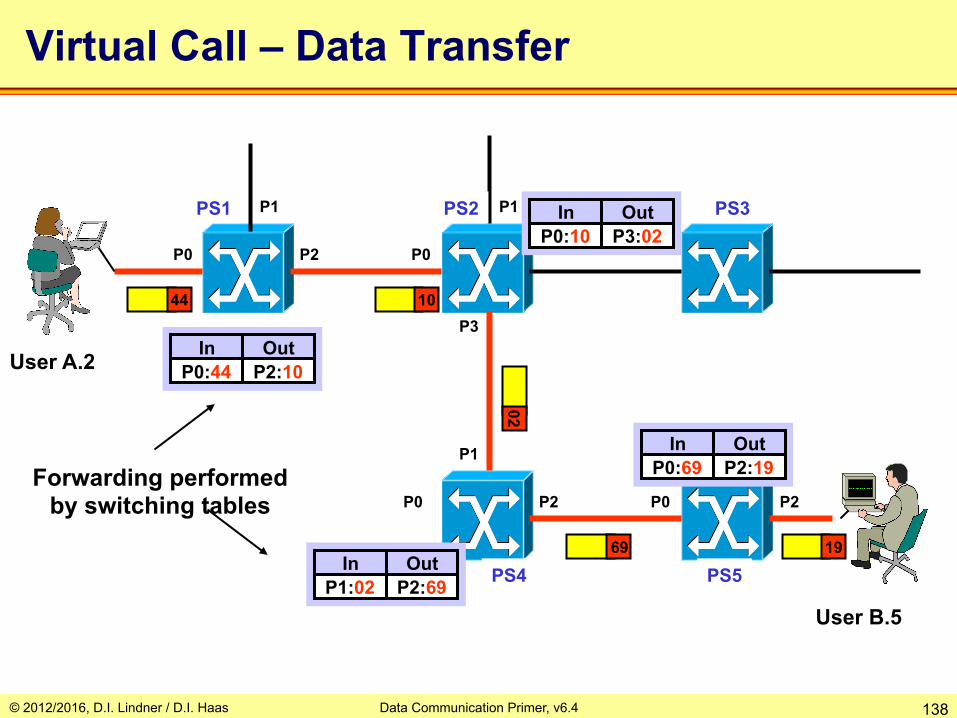
Virtual Call – Data Transfer
P1 P1
P2
P3
P0 P0
P1
P2 P0 P0 P2
User A.2
User B.5
PS1 PS2 PS3
PS4 PS5
P2 P0 In Out P0:10 P3:02
In Out P0:69 P2:19
In Out P1:02 P2:69
In Out P0:44 P2:10
44 10
02
69 19
Forwarding performed by switching tables

© 2012/2016, D.I. Lindner / D.I. Haas Data Communication Primer, v6.4 139
Taxonomy of Network Technologies
Circuit Switching Packet Switching
Dynamic Signalling
Static Configuration Datagram Virtual Call
• Synchronous (Deterministic) Multiplexing
• Low latency (constant delay) • Designed for isochronous
traffic
• Asynchronous (Statistical) Multiplexing
• Store and forward (variable delay)
• Addressing necessary • Designed for data traffic
ISDN
PDH SONET/SDH
IP IPX AppleTalk
X.25 Frame Relay ATM
Connectionless Connection-oriented Q.931, SS7, ... Manual configuration
© 2012/2016, D.I. Lindner / D.I. Haas Data Communication Primer, v6.4 140
Agenda • Physical Aspects
– Serial Transmission, Coding – Framing, Delay Types
• Protocol Basics – Layering / CL versus CO – Error Recovery / Automatic Repeat Request (ARQ) – Windowing, Delay Bandwidth Product, Flow Control
• TDM Basics – Synchronous TDM – Asynchronous TDM
• Network Basics – Circuit Switching – Packet Switching
• Datagram Service / Connectionless Service • Virtual Call Service / Connection-Oriented Service
– Summary • OSI Model – DoD Model

© 2012/2016, D.I. Lindner / D.I. Haas Data Communication Primer, v6.4 141
Application Layer
Presentation Layer
Session Layer
Transport Layer
Network Layer
Link Layer
Physical Layer
Physical Line
real transport peer to peer communication on a logical connection using the layer-specific protocol
The 7 OSI Layers
Application Layer
Presentation Layer
Session Layer
Transport Layer
Network Layer
Link Layer
Physical Layer
7
6
5
4
3
2
1
© 2012/2016, D.I. Lindner / D.I. Haas Data Communication Primer, v6.4 142
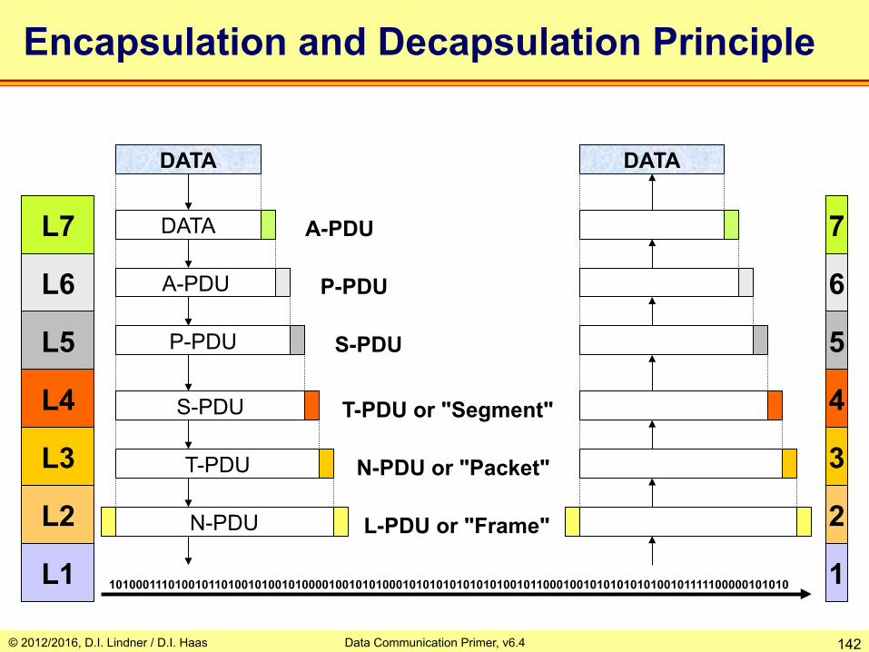
Encapsulation and Decapsulation Principle
L7
L4
L3
L2
L1
L5
L6
DATA
DATA
A-PDU
P-PDU
S-PDU
T-PDU
N-PDU
7
4
3
2
1
5
6
DATA
101000111010010110100101001010000100101010001010101010101010010110001001010101010100101111100000101010
L-PDU or "Frame"
N-PDU or "Packet"
T-PDU or "Segment"
S-PDU
P-PDU
A-PDU

© 2012/2016, D.I. Lindner / D.I. Haas Data Communication Primer, v6.4 143
Practical Encapsulation
Ethernet Frame
IP Packet
TCP Segment
HTTP Message
HTML Webpage
© 2012/2016, D.I. Lindner / D.I. Haas Data Communication Primer, v6.4 144
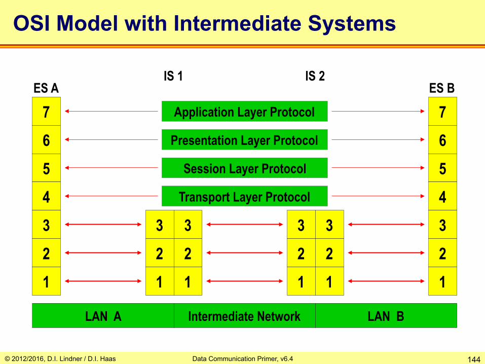
Application Layer Protocol
Presentation Layer Protocol
Session Layer Protocol
Transport Layer Protocol
7 6 5 4 3 2
3 2
3 2
3 2
3 2
7 6 5 4 3 2
1 1 1 1 1 1
LAN A Intermediate Network LAN B
ES A ES B IS 1 IS 2
OSI Model with Intermediate Systems
© 2012/2016, D.I. Lindner / D.I. Haas Data Communication Primer, v6.4 145
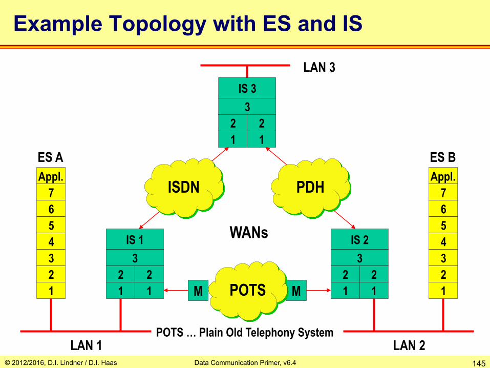
ES A ES B
LAN 1 POTS … Plain Old Telephony System
WANs
7 6 5 4 3 2 1
Appl. 7 6 5 4 3 2 1
Appl. PDH ISDN
IS 2 3
2 2 1 1
IS 1 3
2 2 1 1
LAN 2
M M
IS 3 3
2 2 1 1
Example Topology with ES and IS
POTS
LAN 3

© 2012/2016, D.I. Lindner / D.I. Haas Data Communication Primer, v6.4 146
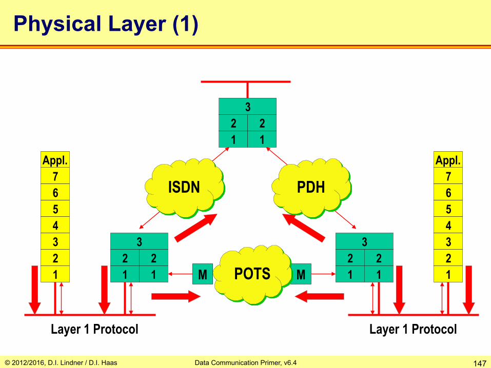
Physical Layer (1)
• Mechanical and electrical specifications
• Access to physical medium • Generates bit stream • Line coding and clocking • Bit synchronization • Link management • Examples
– LAN: Ethernet-PHY, 802.3-PHY – WAN: X.21, I.400 (ISDN),
RS-232
Application Layer
Transport Layer
Network Layer
Data Link Layer
Physical Layer
Session Layer
Presentation Layer
© 2012/2016, D.I. Lindner / D.I. Haas Data Communication Primer, v6.4 147
7 6 5 4 3 2 1
Appl. 7 6 5 4 3 2 1
Appl.
PDH ISDN
3 2 2 1 1
3 2 2 1 1 M M
3 2 2 1 1
Physical Layer (1)
POTS
Layer 1 Protocol Layer 1 Protocol
© 2012/2016, D.I. Lindner / D.I. Haas Data Communication Primer, v6.4 148
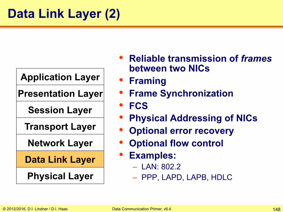
Data Link Layer (2)
• Reliable transmission of frames between two NICs
• Framing • Frame Synchronization • FCS • Physical Addressing of NICs • Optional error recovery • Optional flow control • Examples:
– LAN: 802.2 – PPP, LAPD, LAPB, HDLC
Application Layer
Transport Layer
Network Layer
Data Link Layer
Physical Layer
Session Layer
Presentation Layer

© 2012/2016, D.I. Lindner / D.I. Haas Data Communication Primer, v6.4 149
7 6 5 4 3 2 1
Appl. 7 6 5 4 3 2 1
Appl.
PDH ISDN
3 2 2 1 1
3 2 2 1 1 M M
3 2 2 1 1
Data Link Layer (2)
POTS
Data Link 1
Layer 2 Protocol
Data Link 3 Data Link 2
© 2012/2016, D.I. Lindner / D.I. Haas Data Communication Primer, v6.4 150
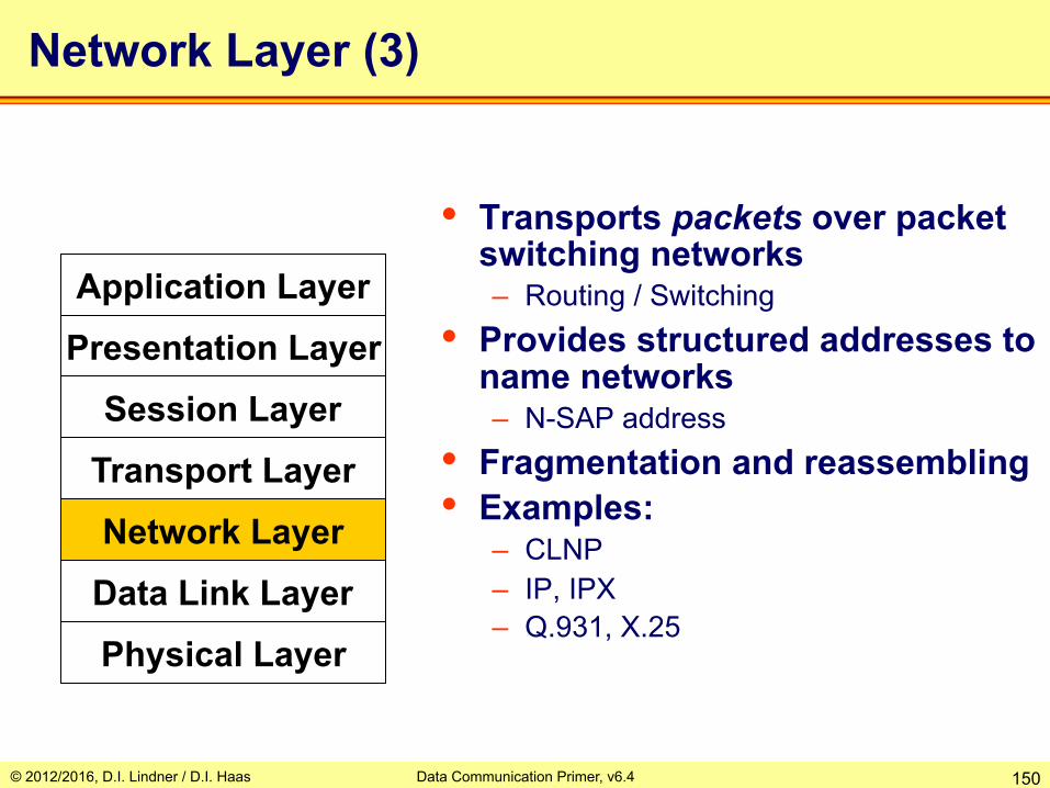
Network Layer (3)
• Transports packets over packet switching networks – Routing / Switching
• Provides structured addresses to name networks – N-SAP address
• Fragmentation and reassembling • Examples:
– CLNP – IP, IPX – Q.931, X.25
Application Layer
Transport Layer
Network Layer
Data Link Layer
Physical Layer
Session Layer
Presentation Layer

© 2012/2016, D.I. Lindner / D.I. Haas Data Communication Primer, v6.4 151
7 6 5 4 3 2 1
Appl. 7 6 5 4 3 2 1
Appl.
PDH ISDN
3 2 2 1 1
3 2 2 1 1 M M
3 2 2 1 1
Network Layer (3)
POTS
Layer 3 Protocol
end-to-end connectivity

© 2012/2016, D.I. Lindner / D.I. Haas Data Communication Primer, v6.4 152
Transport Layer (4)
• Transport of segments between applications (end systems) – Reliable if error recovery by ARQ
• Application multiplexing through T-SAPs – Transport Addresses
• Sequence numbers and Flow control
• Optional QoS Capabilities • Examples:
– TCP (UDP) – ISO 8073 Transport Protocol
Application Layer
Transport Layer
Network Layer
Data Link Layer
Physical Layer
Session Layer
Presentation Layer

© 2012/2016, D.I. Lindner / D.I. Haas Data Communication Primer, v6.4 153
7 6 5 4 3 2 1
Appl. 7 6 5 4 3 2 1
Appl.
PDH ISDN
3 2 2 1 1
3 2 2 1 1 M M
3 2 2 1 1
Transport Layer (4)
POTS
Layer 4 Protocol
© 2012/2016, D.I. Lindner / D.I. Haas Data Communication Primer, v6.4 154
4
ES A
4
ES B
Transport Pipe
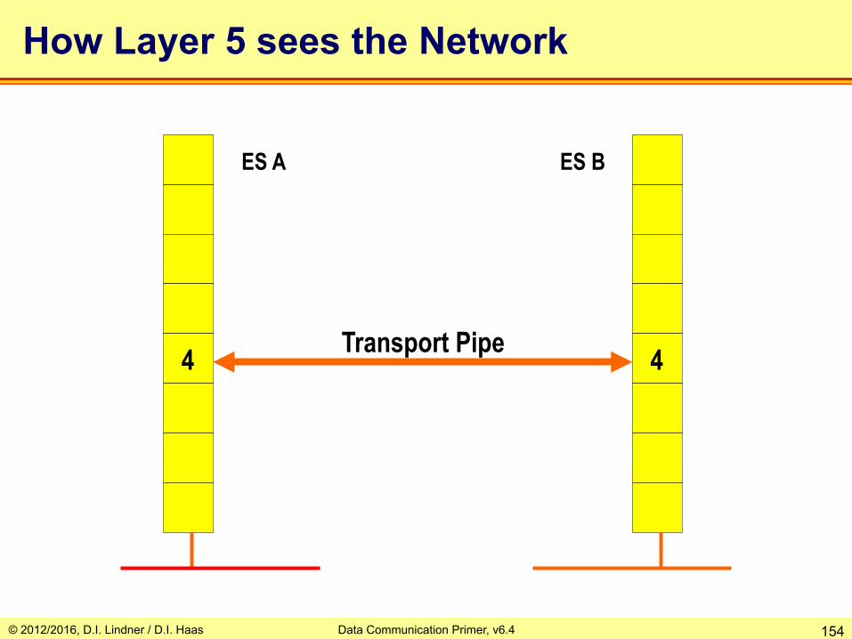
How Layer 5 sees the Network

© 2012/2016, D.I. Lindner / D.I. Haas Data Communication Primer, v6.4 155
Functions of Higher Layers
• Layer 5 (session layer) – Coordinates and controls dialogue between
different end systems • Layer 6 (presentation layer)
– Responsible for common language between end systems (conversion, adaptation of data)
• Layer 7 (application layer) – Supports user with common network applications
(e.g. file transfer, virtual terminal) or basic network procedures in order to implement distributed applications (e.g. transaction systems)

© 2012/2016, D.I. Lindner / D.I. Haas Data Communication Primer, v6.4 156
Session Layer (5)
• Provides a user-oriented connection service – Synchronization Points
• Little capabilities, usually not implemented or part of application layer – Telnet: GA and SYNCH – FTP: re-get allows to continue an
interrupted download – ISO 8327 Session Protocol
Application Layer
Transport Layer
Network Layer
Data Link Layer
Physical Layer
Session Layer
Presentation Layer

© 2012/2016, D.I. Lindner / D.I. Haas Data Communication Primer, v6.4 157
Presentation Layer (6)
• Specifies the data representation format for the application
• Examples: – MIME (part of L7) and UUENCODING
(part of L7) – ISO: ASN.1 and BER
Application Layer
Transport Layer
Network Layer
Data Link Layer
Physical Layer
Session Layer
Presentation Layer

© 2012/2016, D.I. Lindner / D.I. Haas Data Communication Primer, v6.4 158
Application Layer (7)
• Provides network-access for applications
• Examples: – ISO 8571 FTAM File Transfer Access +
Management, X.400 Electronic Mail, CMIP
– SMTP, FTP, SNMP, HTTP, Telnet, DNS, …
Application Layer
Transport Layer
Network Layer
Data Link Layer
Physical Layer
Session Layer
Presentation Layer

© 2012/2016, D.I. Lindner / D.I. Haas Data Communication Primer, v6.4 159
Padlipsky's Rule
If you know what you're doing, three layers is enough. If
you don't, even seventeen won't help.
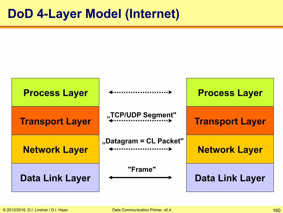
© 2012/2016, D.I. Lindner / D.I. Haas Data Communication Primer, v6.4 160
DoD 4-Layer Model (Internet)
Transport Layer
Network Layer
Data Link Layer
Process Layer
Transport Layer
Network Layer
Data Link Layer
Process Layer
"Frame"
„Datagram = CL Packet"
„TCP/UDP Segment"

© 2012/2016, D.I. Lindner / D.I. Haas Data Communication Primer, v6.4 161
IP transmission over
ATM RFC 1483
IEEE 802.2 RFC 1042
X.25 RFC 1356
FR RFC 1490
PPP RFC 1661
TCP/IP Protocol Suite
Physical
Link
Network
Transport
Session
Presentation
Application SMTP HTTP HTTPS FTP Telnet
SSH DNS DHCP (BootP) TFTP etc.
TCP (Transmission Control Protocol)
UDP (User Datagram
Protocol)
IP (Internet Protocol) ICMP
ARP RARP
Routing Protocols
RIP OSPF BGP
( US-ASCII and MIME )
( RPC )
© 2012/2016, D.I. Lindner / D.I. Haas Data Communication Primer, v6.4 162
The Internet perspective is implement it, make it work well, then write it down.
The OSI perspective is to agree on it, write it down, circulate it a lot and now we'll see if
anyone can implement it after it's an international standard and every vendor in the
world is committed to it.
One of those processes is backwards, and I don't think it takes a Lucasian professor of
physics at Oxford to figure out which.
Marshall Rose, "The Pied Piper of OSI"

© 2012/2016, D.I. Lindner / D.I. Haas Data Communication Primer, v6.4 163
Layer 1 Devices
• Adapts to different physical interfaces • Amplifies and/or refreshes the physical signal • No intelligence • Examples: Repeater, Hub, ISDN NT1
Application
Transport Network
Data Link Physical
Session Presentation
Application
Transport Network
Data Link Physical
Session Presentation
Repeater

© 2012/2016, D.I. Lindner / D.I. Haas Data Communication Primer, v6.4 164
Layer 2 Devices
• Filter/Forwards frames according Link Layer Address • Incorporates Layer 1-2 • LAN-Bridge (“Ethernet Switch")
Application
Transport Network
Data Link Physical
Session Presentation
Application
Transport Network
Data Link Physical
Session Presentation
Bridge

© 2012/2016, D.I. Lindner / D.I. Haas Data Communication Primer, v6.4 165
Layer 3 Devices
• "Packet Switch" or "Intermediate System" • Forwards packets to other networks
according structured address • Terminates Links • IP Router,
WAN-Switch – X.25 – Frame-Relay – ATM
Application
Transport Network
Data Link Physical
Session Presentation
Application
Transport Network
Data Link Physical
Session Presentation
Router
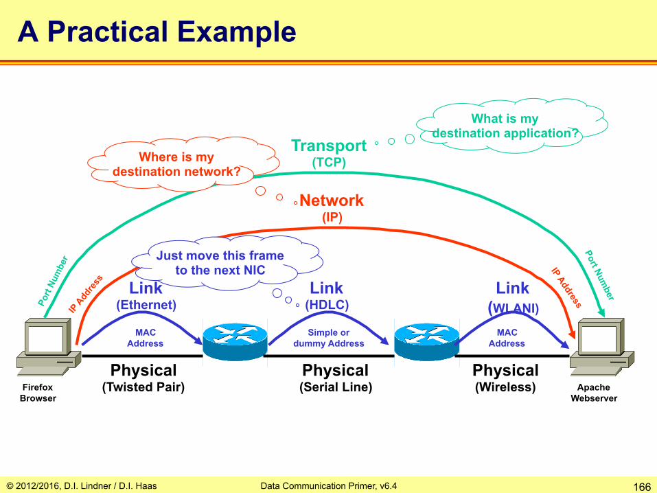
© 2012/2016, D.I. Lindner / D.I. Haas Data Communication Primer, v6.4 166
A Practical Example
Physical (Twisted Pair)
Physical (Serial Line)
Physical (Wireless)
Link (Ethernet)
Link (HDLC)
Link (WLANI)
Network (IP)
Transport (TCP)
Firefox Browser
Apache Webserver
MAC Address
MAC Address
Simple or dummy Address
What is my destination application?
Where is my destination network?
Just move this frame to the next NIC