Embed Size (px)
Citation preview
Introduction and Overview to Switches and Derailsto Switches and Derails
Course 102PARTICIPANT GUIDEPARTICIPANT GUIDEPR
EVIE
W O
NLY

Page Intentionally Left Blank
PREV
IEW O
NLY
Introduction and Overview to Switches and Derails
Participant Guide
Signals Maintenance Training Consortium
COURSE 102
April 2019 Version
PREV
IEW O
NLY
COURSE 102: INTRODUCTION AND OVERVIEW TO SWITCHES AND DERAILS
© 2019 Transportation Learning Center Content may have been modified by a member location. Original available on www.transittraining.net
i
Disclaimer: This module is intended to educate employees of transit agencies that have agreed to voluntarily participate in the Signals Maintenance Consortium. It is intended only as informal guidance on the matters addressed, and should not be relied upon as legal advice. Anyone using this document or information provided in the associated training program should rely on his or her own independent judgment or, as appropriate, seek the advice of a competent professional in determining the exercise of care in any given circumstances. The Signals Consortium, it’s participating agencies and labor unions, as well as the Transportation Learning Center, make no guaranty or warranty as to the accuracy or completeness of any information provided herein. The Signals Consortium, its participating agencies and labor unions, as well as the Transportation Learning Center, disclaims liability for any injury or other damages of any nature whatsoever, directly or indirectly, resulting from the use of or reliance on this document or the associated training program.
NOTE: All images contained within this document were contributed by Signals Training Consortium members unless otherwise noted.
PREV
IEW O
NLY
COURSE 102: INTRODUCTION AND OVERVIEW TO SWITCHES AND DERAILS
© 2019 Transportation Learning Center Content may have been modified by a member location. Original available on www.transittraining.net
ii
TABLE OF CONTENTS PAGE How to Use the Participant Guide .............................................................................................. v
1-1 Overview .............................................................................................................................. 3
1-2 Basic Terminology ............................................................................................................... 8
1-3 Switch Configurations ........................................................................................................ 20
1-4 Switch Types and Mechanical Operations ......................................................................... 27
1-5 Derails ................................................................................................................................. 44
1-6 Electrical Workings of Switch Machines and Derails ........................................................ 49
1-7 Summary ............................................................................................................................. 53
PREV
IEW O
NLY
COURSE 102: INTRODUCTION AND OVERVIEW TO SWITCHES AND DERAILS
© 2019 Transportation Learning Center Content may have been modified by a member location. Original available on www.transittraining.net
iii
LIST OF FIGURES Figure 1 Switch with Main Components Labeled ........................................................................... 3 Figure 2 Wheel Flange on Rail ....................................................................................................... 4 Figure 3 Rail Braces ....................................................................................................................... 5 Figure 4 Switch Highlighting Rods................................................................................................. 5 Figure 5 Split Point Derail: Diagram ............................................................................................ 7 Figure 6 Split Point Derail ............................................................................................................. 7 Figure 7 Facing end of the Switch .................................................................................................. 8 Figure 8 Trailing end of the Switch ................................................................................................ 8 Figure 9 Point Marked with "R" and "N" in Normal Position ....................................................... 9 Figure 10 Point Marked with "R" and "N" in Reverse Position ..................................................... 9 Figure 11 Point in Reverse Position, Normal Position Marked in Yellow ..................................... 9 Figure 12 Example Track Plan - Courtesy of GCRTA ................................................................. 14 Figure 13 Rail Identification Markings ........................................................................................ 15 Figure 14 Diagram Showing Where to Take Track Dimension Measurements ........................... 16 Figure 15 Damaged Knife-Blade Point ........................................................................................ 17 Figure 16 Standard Knife-blade point .......................................................................................... 17 Figure 17 Housed Point ................................................................................................................ 17 Figure 18 Tag on Point ................................................................................................................. 18 Figure 19 Switch Print with Important Parts Labeled ................................................................. 19 Figure 20 Single Crossover .......................................................................................................... 20 Figure 21 Double Crossover ........................................................................................................ 20 Figure 22 Diamond Crossover ..................................................................................................... 20 Figure 23 Track Showing Movable Point Frog and Slip Switch - Courtesy LIRR ....................... 21 Figure 24 Double Slip Switch Diagram – Courtesy of LIRR........................................................ 22 Figure 25 Single Slip Switch ......................................................................................................... 23 Figure 26 Configuration with Helper Switch ............................................................................... 24 Figure 27 Fixed Frog.................................................................................................................... 25 Figure 28 Spring Frog .................................................................................................................. 25 Figure 29 Singular Movable Point Frog with Swing nose Point.................................................. 25 Figure 30 Multiple Movable Point Frog ...................................................................................... 25 Figure 31 Illustration of Operating and Point Detector Rod ....................................................... 28 Figure 32 Locking Mechanism of an Electro-Pneumatic Switch ................................................. 28 Figure 33 Point Detector and Indication Contacts ...................................................................... 29 Figure 34 Manual Switch and Electric Lock ................................................................................ 31 Figure 35 Electric Switch with Dual Control ............................................................................... 31 Figure 36 Electro-Pneumatic Switch ............................................................................................ 31 Figure 37 Electro-Hydraulic Switch Machine .............................................................................. 31 Figure 38 Hand-Throw Switch Stands (Source: http://mysite.du.edu/~jcalvert/railway/turnout.htm) ..................................................................... 33 Figure 39 Red Flag Signals Divergent Tracks ............................................................................. 33 Figure 40 White Flag Signals Convergent Tracks ....................................................................... 33 Figure 41 Electric Switch Highlighting Main Sections with Covers in Place .............................. 34 Figure 42 Electric Switch with Covers Removed Highlighting Main Components ...................... 34 Figure 43 Basic Components of an A-5 Electro-Pneumatic Switch ............................................. 36
PREV
IEW O
NLY
COURSE 102: INTRODUCTION AND OVERVIEW TO SWITCHES AND DERAILS
© 2019 Transportation Learning Center Content may have been modified by a member location. Original available on www.transittraining.net
iv
Figure 44 Control Pneumatic Valve Illustrating Solenoids and Hoses ........................................ 37 Figure 45 Diagram Depicting Solenoid Movement Related to Piston for Normal and Reverse Position as Shown from the Track Side ........................................................................................ 37 Figure 46 Mushroom from Cylinder Engaged with Claw on Slide Bar ....................................... 38 Figure 47 H&K Switch Machine .................................................................................................. 39 Figure 48 H&K Switch Highlighting Valves and Hoses .............................................................. 40 Figure 49 H&K Sequence of Operation ....................................................................................... 42 Figure 50 H&K Switch ................................................................................................................. 42 Figure 51 H&K Tongue Detector Components ............................................................................ 43 Figure 52 Split Point Derail: Diagram ........................................................................................ 45 Figure 53 Split Point Derail ......................................................................................................... 45 Figure 54 Motorized Lifting Block Derailer ................................................................................. 46 Figure 55 Hand-Thrown Pipe Connected Derail ......................................................................... 47 Figure 56 Portable Block Derail .................................................................................................. 48 Figure 57 Generic Block diagram - control, motor and indication circuit .................................. 49 Figure 58 Electric Switch Highlighting Switch Machine and Junction Box ................................ 49 Figure 59 Central Instrument Location ........................................................................................ 50 Figure 60 Print of Electric Switch Showing Entire System .......................................................... 50 Figure 61 Print for an Electric Switch Motor in Normal Position ............................................... 52 Figure 62 Print for an Electric Switch Motor in Reverse Position .............................................. 52
PREV
IEW O
NLY
COURSE 102: INTRODUCTION AND OVERVIEW TO SWITCHES AND DERAILS
© 2019 Transportation Learning Center Content may have been modified by a member location. Original available on www.transittraining.net
v
How to Use the Participant Guide
Purpose of the Course The purpose of the Introduction and Overview to Switches and Derails course is to assist the participant in demonstrating proper safety procedures and gaining an overview the functions of switches, derails, and their associated components.
Approach of the Book Each course module begins with an outline, a statement of purpose and objectives, and a list of key terms. The outline will discuss the main topics to be addressed in the module. A list of key terms identifies important terminology that will be introduced in this module. Learning objectives define the basic skills, knowledge, and abilities course participants should be able to demonstrate to show that they have learned the material presented in the module. A list of key terms identifies important terminology that will be introduced in each course module. Review exercises conclude each module to assist the participants in reviewing key information.
PREV
IEW O
NLY
COURSE 102: INTRODUCTION AND OVERVIEW OF SWITCHES & DERAILS
© 2019 Transportation Learning Center
Content may have been modified by a member location. Original available on www.transittraining.net 1
Introduction & Overview of Switches & Derails
Outline 1-1 Overview 1-2 Basic Terminology 1-3 Switch Configurations 1-4 Switch Types and Mechanical Operations 1-5 Derails 1-6 Electrical Workings of Switches and Derails 1-7 Summary
Purpose and Objectives: The participant will understand and be able to describe the basic operation and functioning of switches and derails along with the various types that exist on railroads.
Following the completion of this module, the participant should be able to complete the exercises with an accuracy of 70% or greater: • Describe theory of operation and purpose of switches • Identify related components of switches • Differentiate between facing and trailing • Identify common switch symbols • Differentiate between right handed and left handed switch layouts • Determine normal and reverse position of the switch • Describe properties of the switch layout as to be able to communicate with the track
department • Given a switch print, be able to identify installation standards • Describe various types of switch layouts and their main features • Differentiate between different types of switches • Identify normal and reverse configuration on the circuit controller • Identify the different types of motor control voltage • Describe purpose and components of point detection • Identify and describe different types of derails • Describe the operation and purpose of derails
PREV
IEW O
NLY

COURSE 102: INTRODUCTION AND OVERVIEW OF SWITCHES & DERAILS
© 2019 Transportation Learning Center
Content may have been modified by a member location. Original available on www.transittraining.net 2
Key Terms • Air Cylinder • Bellows • Central Instrument
Locations • Claw • Closure Rail • Clutch • Contacts • Control Magnets • Control Pneumatic
Valve (CP Valve) • Control Valve • Control Wire • Crossover • Diamond Crossover • Directional Control
Valve • Double Crossover • Double Slip Switch • Drive Roller • Electric Switch • Electro-Hydraulic
Switch • Electro-Pneumatic
Switch • Facing • Filter • Fixed Point Frog • Friction Lock • Frogs • Gauge • Gauge Plates • Gear Pump • Gear Reduction • Gear Train • Hand crank • Head Blocks • Head Rod • Head Ties • Heat Kink • Heel Blocks • Helper Switch
• Housed Points • Hydraulic Fluid Tank • Indication Contacts • Inlet • Installation Standards • Junction Box • Knife-Blade Point • Left Hand Normally
Closed (LHNC) • Left Hand Normally
Open (LHNO) • Left Hand Switch • Linkages • Lock Box • Lock Guide • Locking Dogs • Locking Rods • Locking Slide • Magnetic détente • Manual Switch • Motion Plate • Motor • Motor Control • Movable Point Frogs
(MPF) • Mushroom • Non-Return Valve • Non-Trailable • Normal Position • One-Way Restrictor • Outlet • Outside Slip Switch • Piston • Point Detector • Point Detector Rod • Point Of Switch (PS) • Points • Pressure Relief Valve • Rail Brace • Rail Dimensions • Rail Type • Rail Weight
• Reverse Position • Right Hand Normally
Closed (RHNC) • Right Hand Normally
Open (RHNO) • Right Hand Switch • Rods • Samson Point • Setting Unit • Single Crossover • Single Slip Switch • Single-Ended Switch • Slide Bar • Slip Switch • Snub resistor • Solenoid Valve
Winding • Solenoid Valves • Spring Frog • Spring Switch. • Stock Rails • Swing Nose Point Frog • Switch Circuit
Controller • Switch Configuration • Switch Heaters • Switch Indication • Switch Layout • Switch Machine • Switch Prints • Switch Stand • Terminal Board • Throw Bar • Track Department • Track Plan • Trailable • Trailing • Turnout
PREV
IEW O
NLY
COURSE 102: INTRODUCTION AND OVERVIEW OF SWITCHES & DERAILS
© 2019 Transportation Learning Center
Content may have been modified by a member location. Original available on www.transittraining.net 3
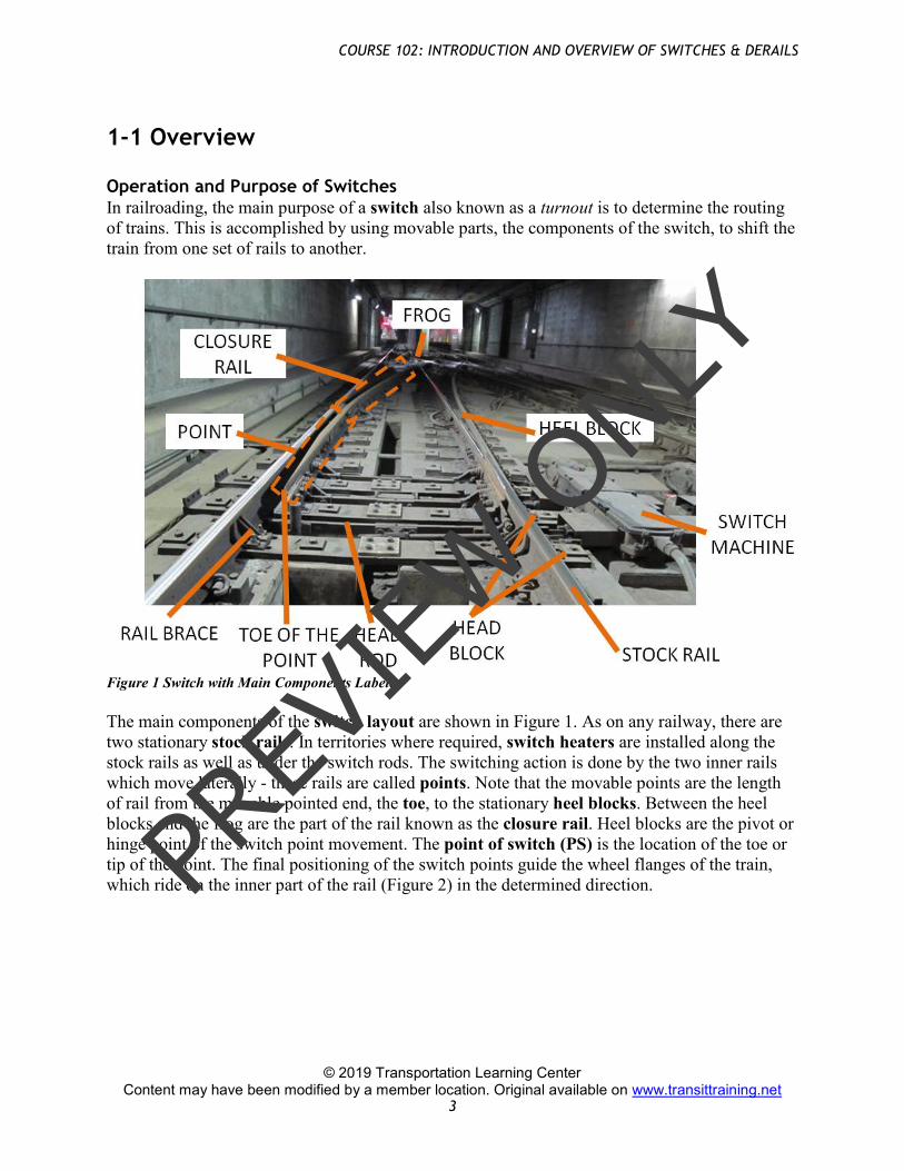
1-1 Overview Operation and Purpose of Switches In railroading, the main purpose of a switch also known as a turnout is to determine the routing of trains. This is accomplished by using movable parts, the components of the switch, to shift the train from one set of rails to another.
Figure 1 Switch with Main Components Labeled The main components of the switch layout are shown in Figure 1. As on any railway, there are two stationary stock rails. In territories where required, switch heaters are installed along the stock rails as well as under the switch rods. The switching action is done by the two inner rails which move laterally - these rails are called points. Note that the movable points are the length of rail from the movable pointed end, the toe, to the stationary heel blocks. Between the heel blocks and the frog are the part of the rail known as the closure rail. Heel blocks are the pivot or hinge point of the switch point movement. The point of switch (PS) is the location of the toe or tip of the point. The final positioning of the switch points guide the wheel flanges of the train, which ride on the inner part of the rail (Figure 2) in the determined direction. PR
EVIE
W O
NLY
COURSE 102: INTRODUCTION AND OVERVIEW OF SWITCHES & DERAILS
© 2019 Transportation Learning Center
Content may have been modified by a member location. Original available on www.transittraining.net 4
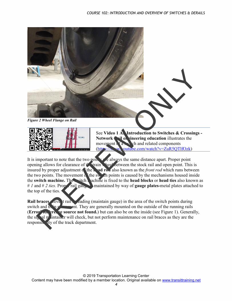
Figure 2 Wheel Flange on Rail
See Video 1 An Introduction to Switches & Crossings - Network Rail engineering education illustrates the movement of a switch and related components (https://www.youtube.com/watch?v=ZuR5QTlfOzk)
It is important to note that the two points are always the same distance apart. Proper point opening allows for clearance of the train wheel between the stock rail and open point. This is insured by proper adjustment of the head rod also known as the front rod which runs between the two points. The movement of the switch points is caused by the mechanisms housed inside the switch machine. The switch machine is fixed to the head blocks or head ties also known as # 1 and # 2 ties. Proper rail gauge is maintained by way of gauge plates-metal plates attached to the top of the ties. Rail braces prevent rail spreading (maintain gauge) in the area of the switch points during switch and train movement. They are generally mounted on the outside of the running rails (Error! Reference source not found.) but can also be on the inside (see Figure 1). Generally, the signal maintainer will check, but not perform maintenance on rail braces as they are the responsibility of the track department. PR
EVIE
W O
NLY
COURSE 102: INTRODUCTION AND OVERVIEW OF SWITCHES & DERAILS
© 2019 Transportation Learning Center
Content may have been modified by a member location. Original available on www.transittraining.net 16
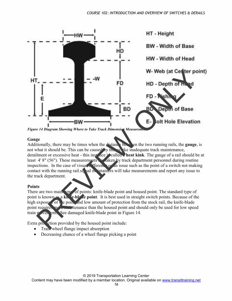
Figure 14 Diagram Showing Where to Take Track Dimension Measurements Gauge Additionally, there may be times when the distance between the two running rails, the gauge, is not what it should be. This can be caused by things like inadequate track maintenance, derailment or excessive heat - this instance is called a heat kink. The gauge of a rail should be at least 4' 8" (56"). These measurements are taken by track department personnel during routine inspections. In the case of visual difference or an issue such as the point of a switch not making contact with the running rail.signal maintainers will take measurements and report any issue to the track department. Points There are two main types of points: knife-blade point and housed point. The standard type of point is known as a knife-blade point. It is best used in straight switch points. Because of the high exposure of the point and low amount of protection from the stock rail, the knife-blade point requires more maintenance than the housed point and should only be used for low speed train movements. See damaged knife-blade point in Figure 14. Extra protection provided by the housed point include:
• Train wheel flange impact absorption • Decreasing chance of a wheel flange picking a point
PREV
IEW O
NLY
COURSE 102: INTRODUCTION AND OVERVIEW OF SWITCHES & DERAILS
© 2019 Transportation Learning Center
Content may have been modified by a member location. Original available on www.transittraining.net 22
Double Slip Switch
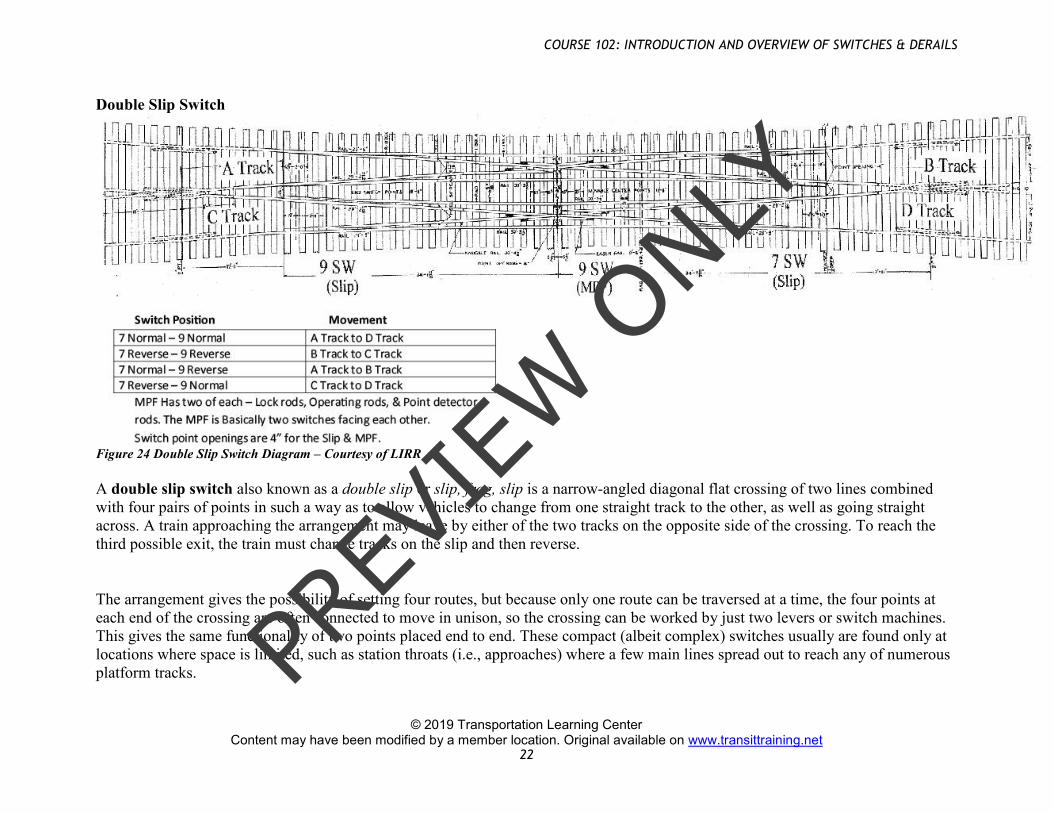
Figure 24 Double Slip Switch Diagram – Courtesy of LIRR A double slip switch also known as a double slip or slip, frog, slip is a narrow-angled diagonal flat crossing of two lines combined with four pairs of points in such a way as to allow vehicles to change from one straight track to the other, as well as going straight across. A train approaching the arrangement may leave by either of the two tracks on the opposite side of the crossing. To reach the third possible exit, the train must change tracks on the slip and then reverse.
The arrangement gives the possibility of setting four routes, but because only one route can be traversed at a time, the four points at each end of the crossing are often connected to move in unison, so the crossing can be worked by just two levers or switch machines. This gives the same functionality of two points placed end to end. These compact (albeit complex) switches usually are found only at locations where space is limited, such as station throats (i.e., approaches) where a few main lines spread out to reach any of numerous platform tracks. PR
EVIE
W O
NLY