Embed Size (px)
Citation preview
PRESTO
Reference Manual
USB In-System Programmer

ASIX s.r.o.Staropramenna 4150 00 PragueCzech Republic
www.asix.net
ASIX s.r.o. reserves the right to make changes to this document, thelatest version of which can be found on the Internet.
ASIX s.r.o. renounces responsibility for any damage caused by the useof ASIX s.r.o. products.
© Copyright by ASIX s.r.o.
Table of Contents
Introduction 91
PRESTO 102
102.1 Package Content
102.2 Features
102.3 Quick Start
10Windows2.3.1
11Linux2.3.2
112.4 Use
11Numerous Supported Devices2.4.1
11USB Connection2.4.2
11Programming of Placed Devices2.4.3
12Programming of Autonomous Devices2.4.4
12Programming Interface2.4.5
12Power Supply From Application2.4.6
12User Interface2.4.7
12Software2.4.8
13Debugging2.4.9
132.5 Controls and Connectors
13Programming Connector2.5.1
14GO Button2.5.2
14LED Indicators2.5.3
ON-LINE 14
ACTIVE 14
14USB Connector2.5.4
152.6 Connecting to Application
15Custom-made Connecting Cable2.6.1
15Programming in ZIF Socket2.6.2
16Connecting Procedure2.6.3
17Connection Examples2.6.4
PIC Microcontrollers 17
AVR Microcontrollers 18
AVR with TPI Interface (e.g. ATtiny10) 18
Atmel 8051 19
Cypress PSoC 19
MSP430 with TEST pin without SBW interface 20
MSP430 / CC430 with SBW interface 20
TI (Chipcon) CCxxxx 21
I2C Memory Chips 21
SPI Memory Chips 21
Microwire Memory Chips 22
JTAG Interface 22
232.7 HPR Adapters
23HPR3V32.7.1
Using 23
23HPR1V22.7.2
Usage 23
24HPRAVR Adapter2.7.3
Use 24
252.8 Built-in Protection
252.9 Technical Specifications
25Limit Values2.9.1
25Operating Specifications2.9.2
26Declaration of Conformity2.9.3
DRIVERS 283
283.1 Driver Installation
28Windows Operating Systems3.1.1
Windows 7 and later 28
Older supported Windows versions 28
29Linux3.1.2
293.2 Driver Updating
UP SOFTWARE 304
304.1 Abbreviations Used
304.2 Installation
304.3 Device Programming
30Programmer Selection4.3.1
31Projects4.3.2
31Device Type Selection4.3.3
32Program settings4.3.4
Delay for VDD switching on/off when supplied fromprogrammer
32
Production Programming Settings 33
Settings for Programming During Development 33
Programmer Settings 34
Fuses and Working with Them 34
34Programming4.3.5
Differential Programming 35
354.4 Further Features
35Setting the GO Button4.4.1
35Mass Production4.4.2
36Serial Numbers4.4.3
Format of Files with Serial Numbers 37
Data Record 37
Example of File with Serial Numbers 38
38Calibration Memory Support4.4.4
Working with Calibration Memory When Erasing aDevice in UV Eraser
38
Working With Calibration Memory in Devices WithFlash Memory
39
394.5 Program Controls
39Toolbar4.5.1
39Status Bar4.5.2
39Menus4.5.3
File Menu 40
File ➙ New 40
File ➙ Open... 40
File ➙ Open next file... 40
File ➙ Reload actual file 40
File ➙ Save 40
File ➙ Save as... 40
File ➙ Import data memory from file... 40
File ➙ Open file with data memory automatically 41
File ➙ New project 41
File ➙ Open project... 41
File ➙ Save project... 41
File ➙ Close project 41
File ➙ Recent projects 41
File ➙ Read calibration data... 41
File ➙ Save calibration data... 41
File ➙ Export to bin... 41
File ➙ Exit 42
Edit Menu 42
Edit ➙ Fill with value... 42
Edit ➙ Text insert... 42
Edit ➙ Fill selected location with RETLW 42
View Menu 42
View ➙ Code/main memory 42
View ➙ Data memory 42
View ➙ Boot memory 43
View ➙ Configuration memory 43
View ➙ Console 43

View ➙ Display code/main memory 43
View ➙ Display data memory 43
View ➙ Display configuration memory 43
Device Menu 43
Device ➙ Program 43
▸ Program all 43
▸ Program all except data memory 43
▸ Program code/main memory 43
▸ Program data memory 44
▸ Program configuration memory 44
▸ Program differentially 44
▸ Differential program data memory 44
▸ Mass Production 44
Device ➙ Read 44
▸ Read all 44
▸ Read all except data memory 44
▸ Read code/main memory 44
▸ Read data memory 45
▸ Read configuration memory 45
Device ➙ Verify 45
▸ Verify all 45
▸ Verify all except data memory 45
▸ Verify code/main memory 45
▸ Verify data memory 45
▸ Verify configuration memory 45
Device ➙ Erase 45
▸ Erase all 45
▸ Erase code/main memory 45
▸ Erase data memory 46
Device ➙ Blank check 46
▸ Blank check all 46
▸ Blank check all except data memory 46
▸ Blank check of code/main memory 46
▸ Blank check of data memory 46
▸ Blank check of configuration memory 46
Device ➙ Select device 46
Options Menu 47
Options ➙ Program settings ➙ Programming 47
▸ Reload file before every programming 47
▸ Warn before file load, when data in someeditor have been changed 47
▸ Warn, when the loaded file has notchanged 47
▸ Ask before erasing 47
▸ Ask before programming of OTP / Flash /Code/Data Protection / differential 47
▸ Display fuse warning messages 47
▸ Except for programming: Close statuswindow 47
▸ After programming: Close status window 48
▸ Beep after successful finishing 48
▸ Beep after unsuccessful finishing 48
▸ Turn off all sound for UP 48
▸ Delay for VDD switching on/off whensupplied from programmer 48
▸ Do not perform blank check before cfgword programming 48
▸ Do not perform blank check after erasing 48
▸ Do not erase device before programming 48
▸ Do not erase data memory before itsprogramming 48
▸ Do not verify unprogrammed words at theend of the memory 49
▸ Do not verify 49
▸ Verify with two supply voltages 49
Options ➙ Program settings ➙ Panels 49
▸ Display selected device on toolbar 49
▸ Display selected programmer on toolbar 49
▸ Display the status bar in the lower part ofthe window 49
▸ Display icons on toolbar buttons 49
▸ Display descriptions on toolbar buttons 49
▸ Show mass production counter in statusbar 49
Options ➙ Program settings ➙ Files 50
▸ File save style 50

▸ Automatically check for newer versions ofactual file 50
▸ Check device type when loading .hex file 50
▸ Save device type into .hex file 50
▸ Warn when loaded file does not containCFG memory data 50
▸ Binary file loading and saving style 50
▸ Save unused locations to .hex file 50
▸ Clear code/main / data memory / IDpositions before file reading 50
▸ Erase configuration memory before filereading 51
▸ Read data memory not from the file butfrom the device 51
▸ Read ID positions not from the file butfrom the device 51
▸ Project saving style 51
Options ➙ Program settings ➙ Colors 51
Options ➙ Program settings ➙ Editors 51
▸ Code/main memory editor: show words asbytes 51
▸ Code/main memory editor 8 words wide 51
▸ Data memory editor 8 words wide 52
▸ Boot memory editor 8 words wide 52
▸ Show only the lowest byte of word in ASCII 52
▸ Mask ID positions while reading fromdevice, from file, etc. 52
▸ Mask ID positions during direct user input 52
▸ Configuration memory editor: show cfgword instead of fuses 52
Options ➙ Program settings ➙ Serial numbers 52
▸ Serial numbers 52
▸ Prepare S/N before programming 52
▸ Find successor after programming 52
▸ Prepare S/N after programming 52
▸ Serial number interval 52
▸ Log to file 52
▸ Serial number length (the number ofcharacters) 53
▸ Number base 53
▸ Code as ASCII 53
▸ Initial serial number 53
▸ Next S/N 53
▸ Destination 53
▸ Hexadecimal address of first word 53
▸ Fill with RETLW instruction 53
▸ Characters per word 53
▸ Sequence 53
Options ➙ Program settings ➙ Checksum 53
▸ Show checksum in status bar 53
▸ Checksum algorithm 54
Options ➙ Program settings ➙ Others 54
▸ Update check settings 54
▸ Allow internal and external supplyvoltages collision 54
▸ Do not show warning if internal 5 V isswitched on with 3.3 V device 54
▸ Allow to change supply voltage level whenit is on 54
Options ➙ Select programmer 54
Options ➙ Language selection... 54
Options ➙ Keyboard shortcuts... 55
Help Menu 55
Help ➙ Help on program 55
Help ➙ List of supported devices 55
Help ➙ Check Internet for updates 55
Help ➙ ASIX website 55
Help ➙ About 55
55Programmer Settings Window4.5.4
FORTE Programmer Settings Window 55
Power supply from the programmer 55
In idle state 55
During programming 55
Reset 55
Settings Associated with PIC Microcontrollers 55
▸ Programming method 56
▸ Use PE 56
Boot memory programming 56
Settings Associated with AVR and 8051Microcontrollers 56
Oscillator frequency 56
Faster Programming with Slow Clock 56
Inverse Reset 56
HVP 56
Settings Associated with I2C Memory Chips 56
I2C Bus Speed 56
I2C Memory Address 56
PRESTO Programmer Settings Window 56
In idle state 56
During programming 56
Settings Associated with PIC Microcontrollers 57
MCLR Pin Control 57
Programming Method 57
Algorithm Programming 57
Use PE 57
Boot memory programming 57
Settings Associated with AVR and 8051Microcontrollers 57
Oscillator Frequency 57
Faster Programming with Slow Clock 57
Inverse Reset 57
HVP 57
Settings Associated with I2C Memory Chips 58
I2C Bus Speed 58
I2C Memory Address 58
58HEX Editor Windows4.5.5
Selecting an Area 58
Code/Main Memory Editor 58
Data Memory (EEPROM) Editor 58
Configuration Memory Editor 58
Tips for Advanced Users 58
594.6 Running UP from Command Line
59List of Parameters4.6.1
Using a Project File 61
Examples of Use 61
File Opening 61
Device Programming 61
61Program Return Codes4.6.2
614.7 Running UP by Means of WindowsMessages
62List of Commands4.7.1
Example of use 63
644.8 UP_DLL.DLL Library
654.9 Running More Than One Instance of UP
654.10 Access of More UP Instances to OneProgrammer
654.11 Updating UP
664.12 Appendix A UP_DLL.DLL
66Data Types4.12.1
66List of UP variables4.12.2
744.13 Appendix B: Use of ICSP
74Pins Used for Programming4.13.1
HVP Algorithm 74
LVP algorithm (without VPP) 74
Loading of Different Programmer Pins 74
75Power Supply Options4.13.2
Power Supply Capacities in Application 75
76ICSP Connector4.13.3
764.14 Appendix C: Intel‑HEX File Format
76Supported Alternatives of HEX Files4.14.1
77Description of Intel‑HEX File Format4.14.2
Data Record 77
End of File 77
Extended Linear Address 77
Saving Device Type in .hex File 78
PRESTO.DLL Library 795
JTAG PLAYER 806
806.1 JTAG Device Programming
80SVF File6.1.1
Examples of How to Create SVF Files 80
State of .svf File Implementation 81
81XSVF File6.1.2
Examples of How to Create XSVF Files 81
State of XSVF File Implementation 82
82Programming Connector6.1.3
826.2 Settings
82Default TCK signal frequency6.2.1
83Fast Clocks Option (FORTE only)6.2.2
83RUNTEST without run_count (SVF only)6.2.3
83RUNTEST Timing Multiply (both SVF and XSVF)6.2.4
83RUNTEST with run_count and no timing(both SVF and XSVF)
6.2.5
84VPP PRESTO / P FORTE pin usage while running test(file) / after test completion
6.2.6
84Default Settings6.2.7
Default Settings for FPGAs 84
Default Settings for XC9500 84
Default Settings for AVR: 84
856.3 Running JTAG Player from Command Line
TROUBLE-SHOOTING 867
867.1 Tips and Tricks
867.2 PRESTO Tester
Document history 888
Page 9
1
Introduction
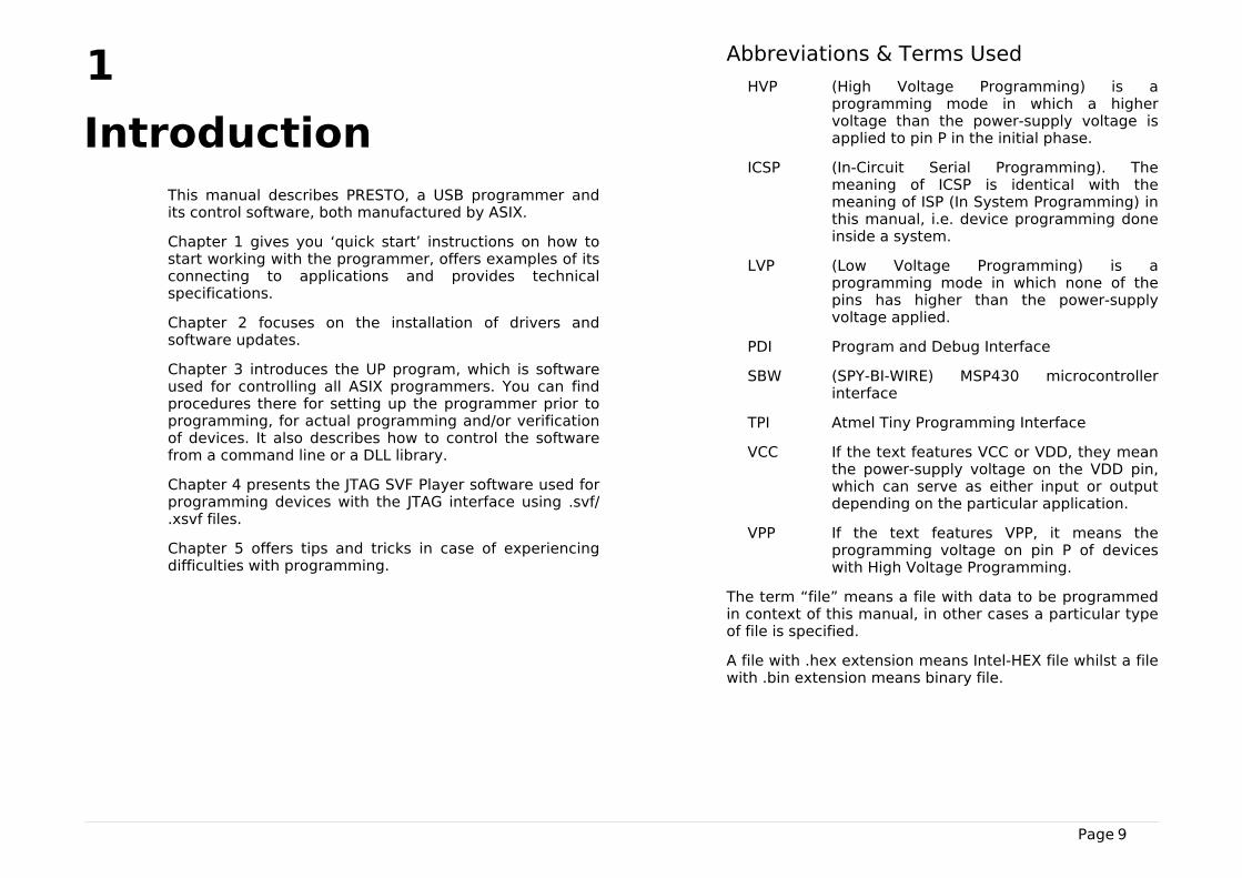
This manual describes PRESTO, a USB programmer andits control software, both manufactured by ASIX.
Chapter 1 gives you ‘quick start’ instructions on how tostart working with the programmer, offers examples of itsconnecting to applications and provides technicalspecifications.
Chapter 2 focuses on the installation of drivers andsoftware updates.
Chapter 3 introduces the UP program, which is softwareused for controlling all ASIX programmers. You can findprocedures there for setting up the programmer prior toprogramming, for actual programming and/or verificationof devices. It also describes how to control the softwarefrom a command line or a DLL library.
Chapter 4 presents the JTAG SVF Player software used forprogramming devices with the JTAG interface using .svf/.xsvf files.
Chapter 5 offers tips and tricks in case of experiencingdifficulties with programming.
Abbreviations & Terms Used
HVP (High Voltage Programming) is aprogramming mode in which a highervoltage than the power-supply voltage isapplied to pin P in the initial phase.
ICSP (In-Circuit Serial Programming). Themeaning of ICSP is identical with themeaning of ISP (In System Programming) inthis manual, i.e. device programming doneinside a system.
LVP (Low Voltage Programming) is aprogramming mode in which none of thepins has higher than the power-supplyvoltage applied.
PDI Program and Debug Interface
SBW (SPY-BI-WIRE) MSP430 microcontrollerinterface
TPI Atmel Tiny Programming Interface
VCC If the text features VCC or VDD, they meanthe power-supply voltage on the VDD pin,which can serve as either input or outputdepending on the particular application.
VPP If the text features VPP, it means theprogramming voltage on pin P of deviceswith High Voltage Programming.
The term “file” means a file with data to be programmedin context of this manual, in other cases a particular typeof file is specified.
A file with .hex extension means Intel-HEX file whilst a filewith .bin extension means binary file.
Page 10
2
PRESTO
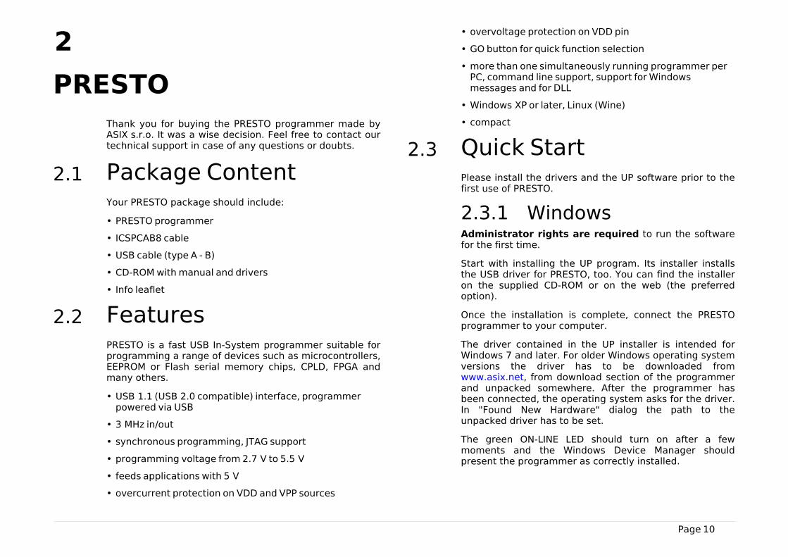
Thank you for buying the PRESTO programmer made byASIX s.r.o. It was a wise decision. Feel free to contact ourtechnical support in case of any questions or doubts.
2.1 Package ContentYour PRESTO package should include:
• PRESTO programmer
• ICSPCAB8 cable
• USB cable (type A - B)
• CD-ROM with manual and drivers
• Info leaflet
2.2 FeaturesPRESTO is a fast USB In-System programmer suitable forprogramming a range of devices such as microcontrollers,EEPROM or Flash serial memory chips, CPLD, FPGA andmany others.
• USB 1.1 (USB 2.0 compatible) interface, programmerpowered via USB
• 3 MHz in/out
• synchronous programming, JTAG support
• programming voltage from 2.7 V to 5.5 V
• feeds applications with 5 V
• overcurrent protection on VDD and VPP sources
• overvoltage protection on VDD pin
• GO button for quick function selection
• more than one simultaneously running programmer perPC, command line support, support for Windowsmessages and for DLL
• Windows XP or later, Linux (Wine)
• compact
2.3 Quick StartPlease install the drivers and the UP software prior to thefirst use of PRESTO.
2.3.1 WindowsAdministrator rights are required to run the softwarefor the first time.
Start with installing the UP program. Its installer installsthe USB driver for PRESTO, too. You can find the installeron the supplied CD-ROM or on the web (the preferredoption).
Once the installation is complete, connect the PRESTOprogrammer to your computer.
The driver contained in the UP installer is intended forWindows 7 and later. For older Windows operating systemversions the driver has to be downloaded fromwww.asix.net, from download section of the programmerand unpacked somewhere. After the programmer hasbeen connected, the operating system asks for the driver.In "Found New Hardware" dialog the path to theunpacked driver has to be set.
The green ON-LINE LED should turn on after a fewmoments and the Windows Device Manager shouldpresent the programmer as correctly installed.

Page 11
2.3.2 LinuxThe programmer can be operated under Wine in Linux.Please find detailed installation instructions at http://www.asix.net/tools/supp_linux.htm
2.4 UsePRESTO is a fast USB programmer suitable forprogramming of a range of devices such asmicrocontrollers, EEPROM or Flash serial memory chips,CPLD, FPGA and many others. It is equipped withovercurrent protection at the VDD and VPP sources andwith overvoltage protection at the VDD pin.
The programmer is powered via USB. It can feed theapplication to be programmed with a voltage of 5 V or itcan utilize an external application’s voltage of 2.7 V to5.5 V during programming.
The programmer may run under Windows XP or later orunder Linux in Wine.
2.4.1 Numerous SupportedDevices
The list of supported devices includes:
• Microchip PIC microcontrollers – devices with serialprogramming, which include all PIC and dsPIC deviceswith the exception of several obsolete types.
• Atmel AVR microcontrollers – all devices supporting"SPI Low Voltage Serial Downloading" such as ATtiny12,AT90S8535 or ATmega128.
• Atmel ATxmega microcontrollers – devicesprogrammable via JTAG interface such asATxmega128A1.
• Atmel AVR32 microcontrollers – AT32UC3A1256, forexample.
• Atmel 8051 microcontrollers – devices that support ISPprogramming such as AT89S8253, AT89LP4052,AT89LP216 or AT89S2051.
• Texas Instruments microcontrollers – 16-bit MSP430,CC430 (fuse programming is not supported for thesefamilies) and CCxxxx.
• Cypress – PSoC microcontrollers.
• Serial EEPROM and Flash memory chips - I2C(24LCxx), Microwire (93LCxx) and SPI (25Cxx).
• Devices with JTAG interface, for which an SVF or anXSVF file can be created. These include CPLD (such asXilinx XC95xx and CoolRunner), configuration memoryfor FPGA (such as Xilinx XC18Vxx and XCFxxS),microcontrollers (such as ATmega128) and others.
This, however, is not an exhausting list of possibilities.Additional types are regularly supplemented in responseto customers’ interest. New software versions aredownloadable from the Internet for free.
2.4.2 USB ConnectionPRESTO is controlled and powered through a USB port. Itcommunicates in the Full-Speed mode and works with aUSB 2.0 port or a USB 1.1 port. This means thatconnecting the programmer is fast and easy, requiringonly a single cable.
2.4.3 Programming ofPlaced Devices
ISP (In-System Programming) or the special ICSP (In-Circuit Serial Programming) for the PIC microcontrollers iscurrently replacing the traditional method in whichdevices were first programmed and only then placed on aPCB (printed circuit board). Thanks to ISP even SMDdevices with an extremely narrowly spaced pins caneasily be programmed and their firmware upgraded inalready assembled and finished devices.
Page 12
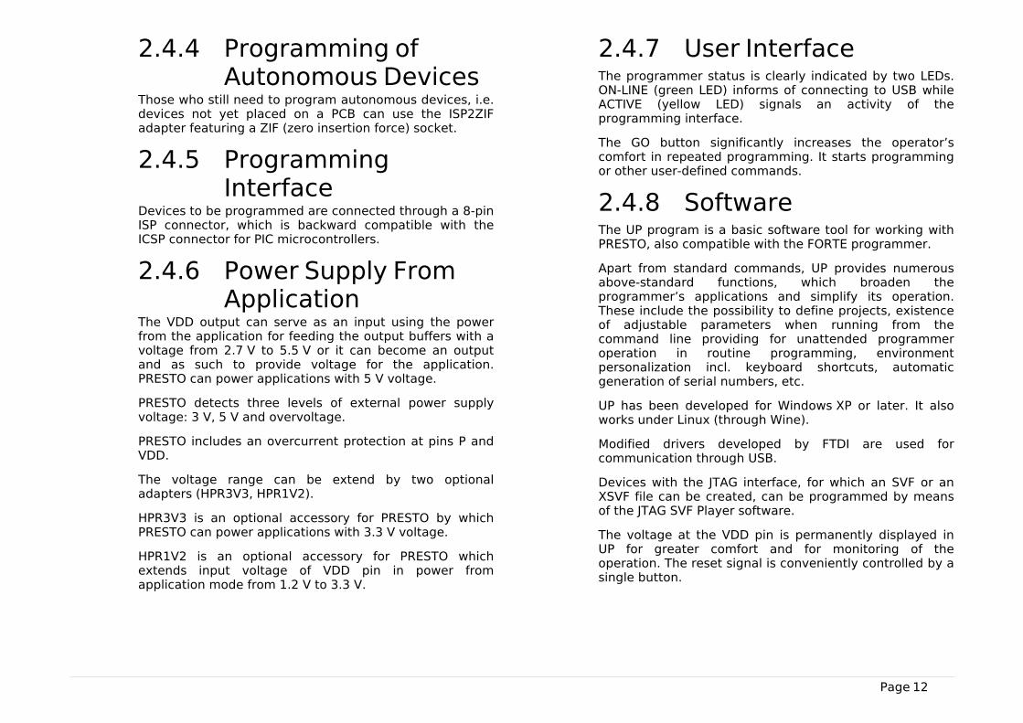
2.4.4 Programming ofAutonomous Devices
Those who still need to program autonomous devices, i.e.devices not yet placed on a PCB can use the ISP2ZIFadapter featuring a ZIF (zero insertion force) socket.
2.4.5 ProgrammingInterface
Devices to be programmed are connected through a 8-pinISP connector, which is backward compatible with theICSP connector for PIC microcontrollers.
2.4.6 Power Supply FromApplication
The VDD output can serve as an input using the powerfrom the application for feeding the output buffers with avoltage from 2.7 V to 5.5 V or it can become an outputand as such to provide voltage for the application.PRESTO can power applications with 5 V voltage.
PRESTO detects three levels of external power supplyvoltage: 3 V, 5 V and overvoltage.
PRESTO includes an overcurrent protection at pins P andVDD.
The voltage range can be extend by two optionaladapters (HPR3V3, HPR1V2).
HPR3V3 is an optional accessory for PRESTO by whichPRESTO can power applications with 3.3 V voltage.
HPR1V2 is an optional accessory for PRESTO whichextends input voltage of VDD pin in power fromapplication mode from 1.2 V to 3.3 V.
2.4.7 User InterfaceThe programmer status is clearly indicated by two LEDs.ON-LINE (green LED) informs of connecting to USB whileACTIVE (yellow LED) signals an activity of theprogramming interface.
The GO button significantly increases the operator’scomfort in repeated programming. It starts programmingor other user-defined commands.
2.4.8 SoftwareThe UP program is a basic software tool for working withPRESTO, also compatible with the FORTE programmer.
Apart from standard commands, UP provides numerousabove-standard functions, which broaden theprogrammer’s applications and simplify its operation.These include the possibility to define projects, existenceof adjustable parameters when running from thecommand line providing for unattended programmeroperation in routine programming, environmentpersonalization incl. keyboard shortcuts, automaticgeneration of serial numbers, etc.
UP has been developed for Windows XP or later. It alsoworks under Linux (through Wine).
Modified drivers developed by FTDI are used forcommunication through USB.
Devices with the JTAG interface, for which an SVF or anXSVF file can be created, can be programmed by meansof the JTAG SVF Player software.
The voltage at the VDD pin is permanently displayed inUP for greater comfort and for monitoring of theoperation. The reset signal is conveniently controlled by asingle button.
Page 13
2.4.9 DebuggingPRESTO provides user with support for debugging ARMmicrocontrollers through OpenOCD which is an opensource debugging system originally developed byDominic Rath. OpenOCD uses GDB for access to debugfunctions. User can communicate with OpenOCD via acommand line and telnet.
The revision 717 of OpenOCD, which can be found on ourwebsite in a program package together with the ARMINEprogram, is supported officially.
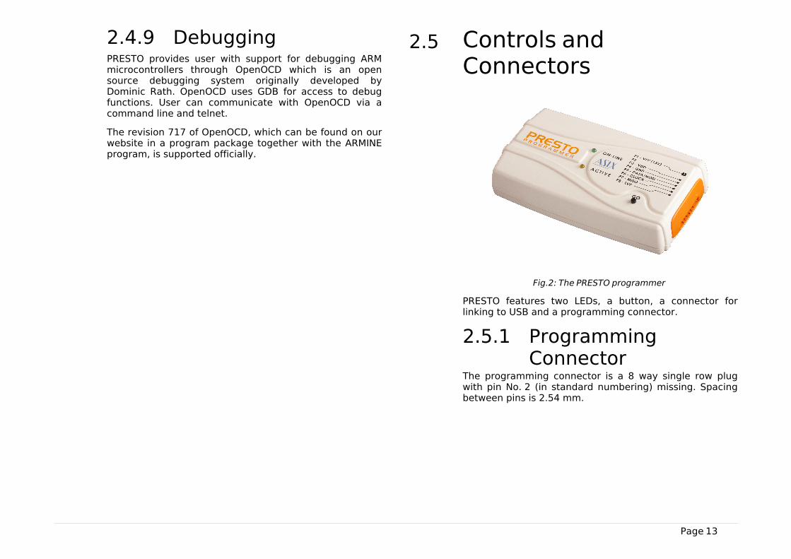
2.5 Controls andConnectors
Fig.2: The PRESTO programmer
PRESTO features two LEDs, a button, a connector forlinking to USB and a programming connector.
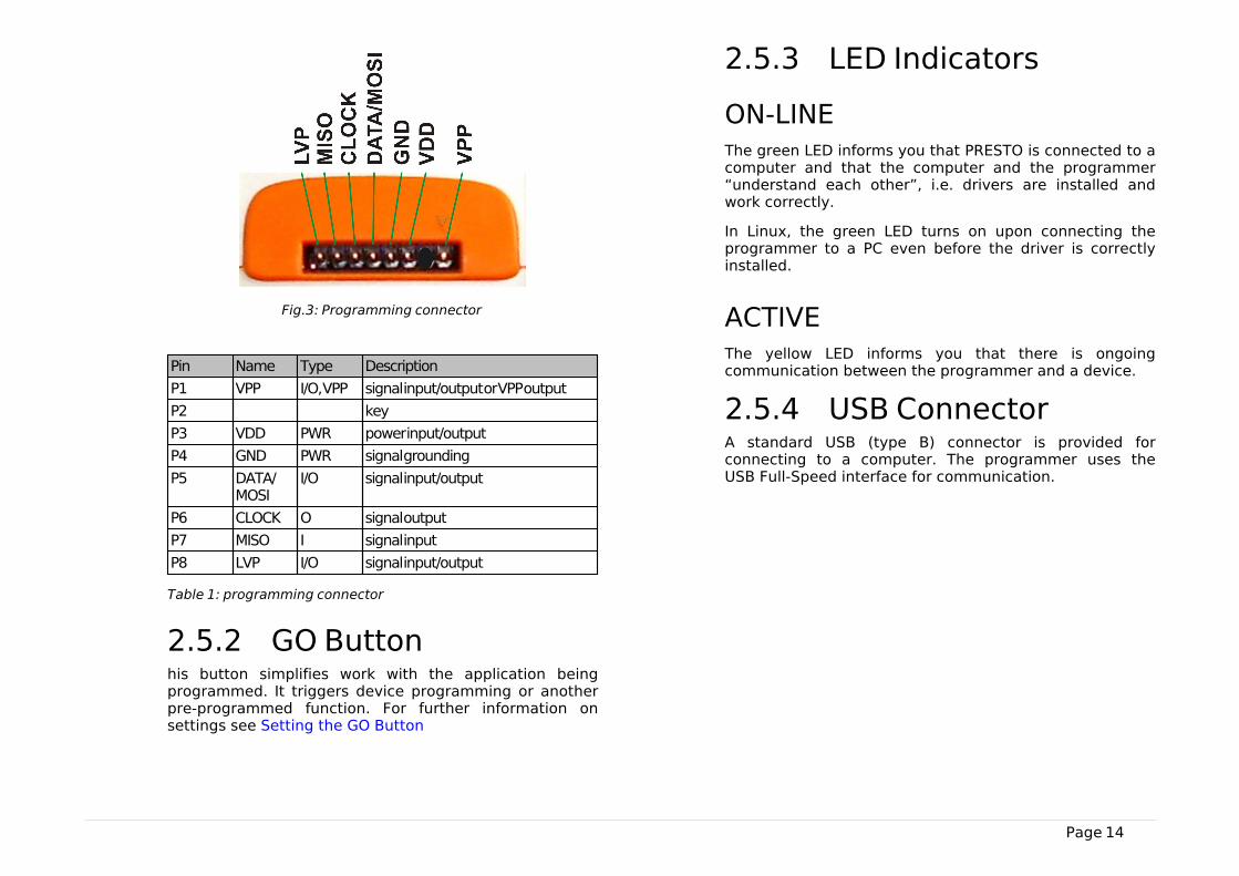
2.5.1 ProgrammingConnector
The programming connector is a 8 way single row plugwith pin No. 2 (in standard numbering) missing. Spacingbetween pins is 2.54 mm.
Page 14
Fig.3: Programming connector
Pin Name Type Description
P1 VPP I/O, VPP signal input/output or VPP output
P2 key
P3 VDD PWR power input/output
P4 GND PWR signal grounding
P5 DATA/MOSI
I/O signal input/output
P6 CLOCK O signal output
P7 MISO I signal input
P8 LVP I/O signal input/output
Table 1: programming connector
2.5.2 GO Buttonhis button simplifies work with the application beingprogrammed. It triggers device programming or anotherpre-programmed function. For further information onsettings see Setting the GO Button
2.5.3 LED Indicators
ON-LINEThe green LED informs you that PRESTO is connected to acomputer and that the computer and the programmer“understand each other”, i.e. drivers are installed andwork correctly.
In Linux, the green LED turns on upon connecting theprogrammer to a PC even before the driver is correctlyinstalled.
ACTIVEThe yellow LED informs you that there is ongoingcommunication between the programmer and a device.
2.5.4 USB ConnectorA standard USB (type B) connector is provided forconnecting to a computer. The programmer uses theUSB Full-Speed interface for communication.
Page 15
2.6 Connecting toApplicationThe programmer should be connected to an application tobe programmed with an ICSPCAB8 which is designed for2.54 mm spacing.
Fig.4: ICSPCAB8
2.6.1 Custom-madeConnecting Cable
Should an application to be programmed have a non-compatible type of connector for linking to theprogrammer, the customer can make his/her ownprogramming cable. Its length should not exceed 15 cm.
The following table lists markings of connectors by FCIElectronics suitable for making a custom cable. Of course,it is possible to use any similar ones:
FCI marking Description
65039-036LF housing, 1 pin
65039-029LF housing, 1 x 8 pins
47217-000LF pin
Table 2: ICSP cable - material list
A cable with a cross-section between 0.1 and 0.3 mm2
may be used for making the custom connecting cable.
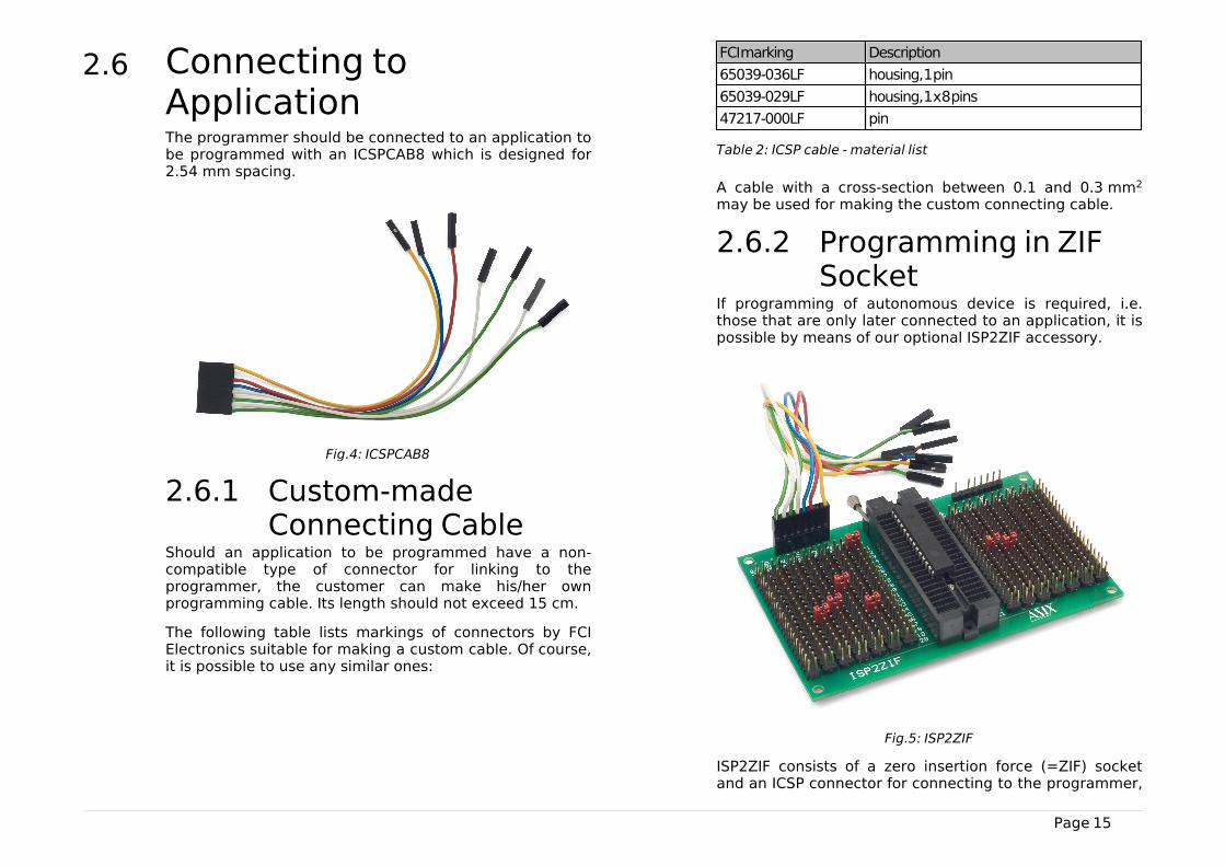
2.6.2 Programming in ZIFSocket
If programming of autonomous device is required, i.e.those that are only later connected to an application, it ispossible by means of our optional ISP2ZIF accessory.
Fig.5: ISP2ZIF
ISP2ZIF consists of a zero insertion force (=ZIF) socketand an ICSP connector for connecting to the programmer,
Page 16
which can also provide voltage for feeding the programcircuitry.
2.6.3 ConnectingProcedure
The correct procedure for connecting the programmer:first connect PRESTO to the target application, thenconnect PRESTO to the USB and finally turn on theapplication’s power supply.
Please make sure that the GND of the application, theprogrammer and the USB are interconnected beforesignals and the power are applied.
Important warning
If an application is powered by a switchedpower source or is not grounded, a significantvoltage difference may appear between theprogrammer’s ground and the application’sground. This could damage the programmer.
The simplest way of connecting the GND prior to theother signals is to ground the application beforeconnecting it to the programmer. This can, for example,be achieved by making the GND pin of the application’sICSP connector longer than the other pins. It will makesure that both grounds are interconnected first.
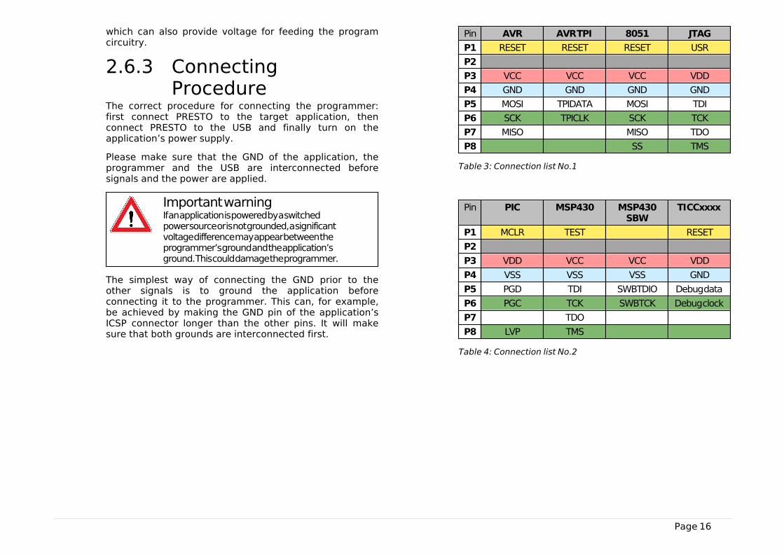
Pin AVR AVR TPI 8051 JTAG
P1 RESET RESET RESET USR
P2
P3 VCC VCC VCC VDD
P4 GND GND GND GND
P5 MOSI TPIDATA MOSI TDI
P6 SCK TPICLK SCK TCK
P7 MISO MISO TDO
P8 SS TMS
Table 3: Connection list No.1
Pin PIC MSP430 MSP430SBW
TI CCxxxx
P1 MCLR TEST RESET
P2
P3 VDD VCC VCC VDD
P4 VSS VSS VSS GND
P5 PGD TDI SWBTDIO Debug data
P6 PGC TCK SWBTCK Debug clock
P7 TDO
P8 LVP TMS
Table 4: Connection list No.2
Page 17
Pin PSoC I2C SPI Microwire
P1 XRST CS CS
P2
P3 VDD VDD VDD VDD
P4 VSS GND GND GND
P5 ISSP-data SDA SI DI
P6 ISSP-SCLK SCL SCK CLK
P7 SO DO
P8 ORG (PRE)
Table 5: Connection list No.3
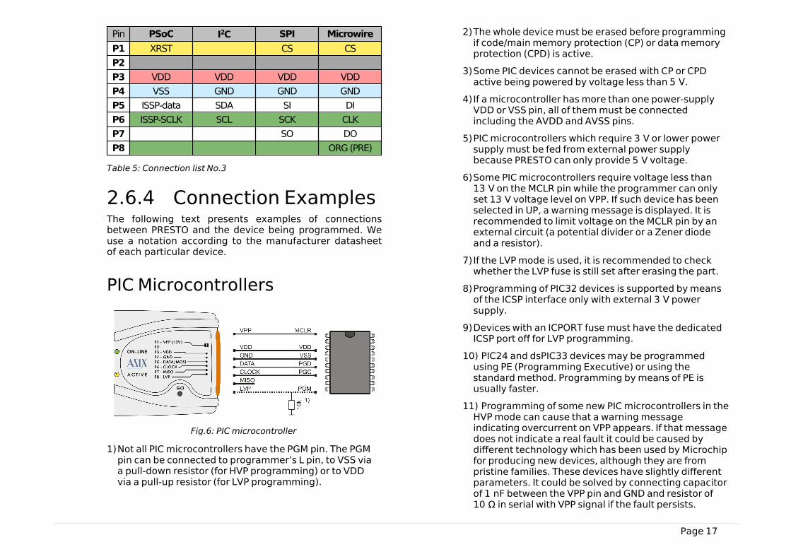
2.6.4 Connection ExamplesThe following text presents examples of connectionsbetween PRESTO and the device being programmed. Weuse a notation according to the manufacturer datasheetof each particular device.
PIC Microcontrollers
Fig.6: PIC microcontroller
1)Not all PIC microcontrollers have the PGM pin. The PGMpin can be connected to programmer’s L pin, to VSS viaa pull-down resistor (for HVP programming) or to VDDvia a pull-up resistor (for LVP programming).
2)The whole device must be erased before programmingif code/main memory protection (CP) or data memoryprotection (CPD) is active.
3)Some PIC devices cannot be erased with CP or CPDactive being powered by voltage less than 5 V.
4)If a microcontroller has more than one power-supplyVDD or VSS pin, all of them must be connectedincluding the AVDD and AVSS pins.
5)PIC microcontrollers which require 3 V or lower powersupply must be fed from external power supplybecause PRESTO can only provide 5 V voltage.
6)Some PIC microcontrollers require voltage less than13 V on the MCLR pin while the programmer can onlyset 13 V voltage level on VPP. If such device has beenselected in UP, a warning message is displayed. It isrecommended to limit voltage on the MCLR pin by anexternal circuit (a potential divider or a Zener diodeand a resistor).
7)If the LVP mode is used, it is recommended to checkwhether the LVP fuse is still set after erasing the part.
8)Programming of PIC32 devices is supported by meansof the ICSP interface only with external 3 V powersupply.
9)Devices with an ICPORT fuse must have the dedicatedICSP port off for LVP programming.
10) PIC24 and dsPIC33 devices may be programmedusing PE (Programming Executive) or using thestandard method. Programming by means of PE isusually faster.
11) Programming of some new PIC microcontrollers in theHVP mode can cause that a warning messageindicating overcurrent on VPP appears. If that messagedoes not indicate a real fault it could be caused bydifferent technology which has been used by Microchipfor producing new devices, although they are frompristine families. These devices have slightly differentparameters. It could be solved by connecting capacitorof 1 nF between the VPP pin and GND and resistor of10 Ω in serial with VPP signal if the fault persists.

Page 18
AVR Microcontrollers
Fig.7: AVR microcontroller
1)A source of the clock signal, which is set in the deviceor which will be set by fuses during programming mustbe connected to the device. A crystal must beconnected if set up as the clock source.
2)Device fuses have been set up by the producer to theinternal oscillator with a frequency of 1 MHz. In theinitial programming, the device should be programmedwith “Oscillator frequency” set up at “>750 kHz” orlower in the “PRESTO programmer settings”window.
3)Not all AVR microcontrollers allow use of a crystal(e.g. ATtiny13, ATtiny15).
4)After the device fuses are correctly set up, right-click(i.e. using the right mouse button) inside the Configuration window and choose Learn fuses. Thissaves the fuses in the up.ini file or in the project if used.This is necessary due to the fact that .hex files for AVRmicrocontrollers themselves do not containconfiguration fuses. If a device is programmed from thecommand line, a .ppr project file containing saved fusesneeds to be used.
5)Ticking the Open file with data memoryautomatically option in the File menu loads data forthe data memory simultaneously with the code/mainmemory data.
6)Use the EESAVE fuse if preservation of data memory isrequired. If the EESAVE is active, choose Program allexcept data memory for programming, otherwise awarning appears at this place (blank check of datamemory).
7)HPR3V3 is an optional accessory for programming AVRmicrocontrollers which reguire 3.3 V voltage withPRESTO internal 5 V power supply.
8)HPRAVR is an optional accessory for programming AVRmicrocontrollers in applications with the ISP10PINstandard connector on the device's side.
9)Some AVR devices have their ISP interface provided atdifferent pins than the SPI interface. Furtherinformation can be found in the device data sheet (inthe Serial Downloading section).
AVR with TPI Interface (e.g.ATtiny10)
Fig.8: AVR microcontroller, TPI interface
1)These microcontrollers require voltage 12 V on theRESET pin during programming in the HVP mode whilethe programmer can only set 13 V voltage level on VPP.Therefore it is necessary to limit voltage on the RESETpin by an external circuit. There is no need of anyexternal circuit for the LVP mode which is preferred.
Page 19
Atmel 8051
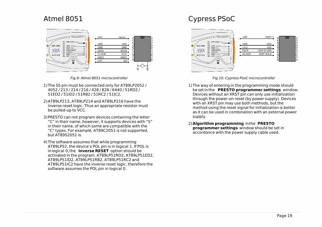
Fig.9: Atmel 8051 microcontroller
1)The SS pin must be connected only for AT89LP2052 /4052 / 213 / 214 / 216 / 428 / 828 / 6440 / 51RD2 /51ED2 / 51ID2 / 51RB2 / 51RC2 / 51IC2.
2)AT89LP213, AT89LP214 and AT89LP216 have theinverse reset logic. Thus an appropriate resistor mustbe pulled-up to VCC.
3)PRESTO can not program devices containing the letter“C” in their name, however, it supports devices with “S”in their name, of which some are compatible with the“C” types. For example, AT89C2051 is not supported,but AT89S2051 is.
4)The software assumes that while programmingAT89LP52, the device’s POL pin is in logical 1. If POL isin logical 0, the Inverse RESET option should beactivated in the program. AT89LP51RD2, AT89LP51ED2,AT89LP51ID2, AT89LP51RB2, AT89LP51RC2 andAT89LP51IC2 have the inverse reset logic, therefore thesoftware assumes the POL pin in logical 0.
Cypress PSoC
Fig.10: Cypress PsoC microcontroller
1)The way of entering in the programming mode shouldbe set in the PRESTO programmer settings window.Devices without an XRST pin can only use initializationthrough the power-on reset (by power supply). Deviceswith an XRST pin may use both methods, but themethod using the reset signal for initialization is betteras it can be used in combination with an external powersupply.
2)Algorithm programming in the PRESTOprogrammer settings window should be set inaccordance with the power supply cable used.
Page 20
MSP430 with TEST pin withoutSBW interface
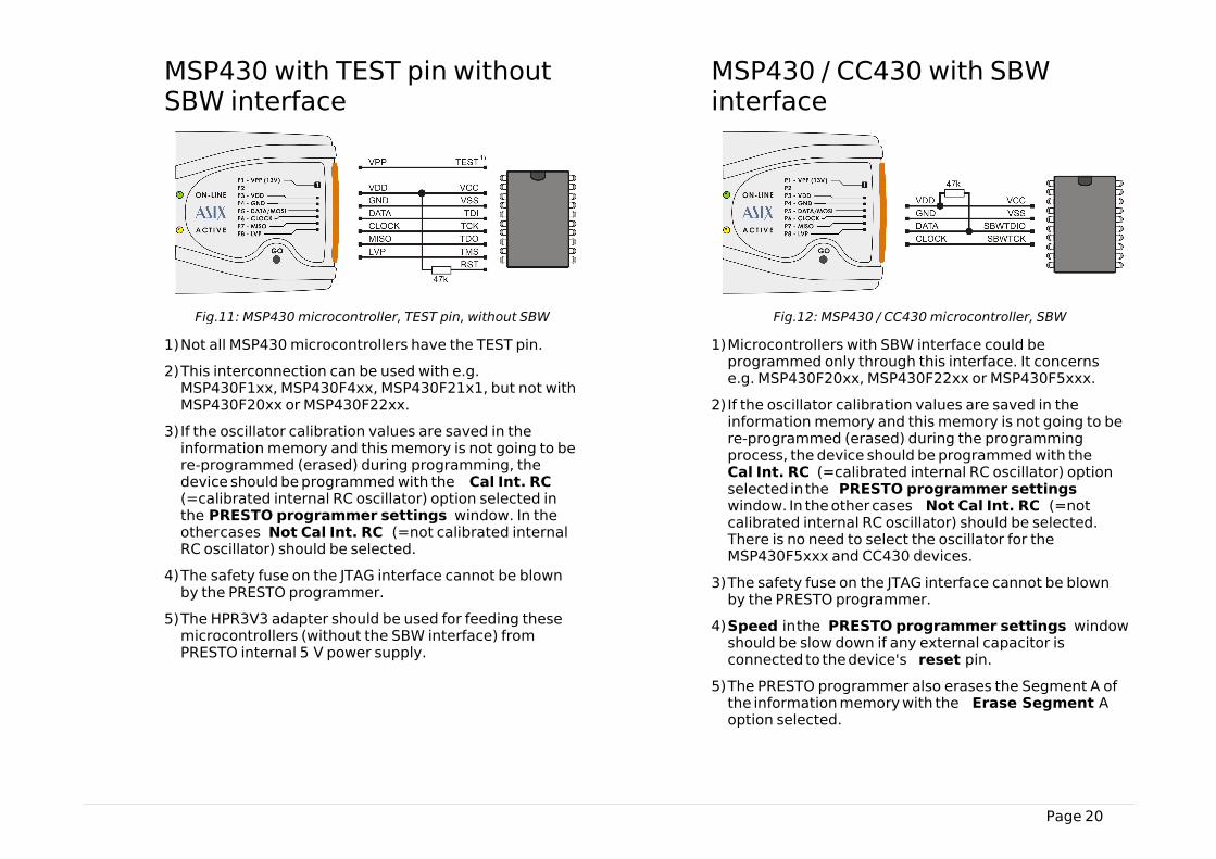
Fig.11: MSP430 microcontroller, TEST pin, without SBW
1)Not all MSP430 microcontrollers have the TEST pin.
2)This interconnection can be used with e.g.MSP430F1xx, MSP430F4xx, MSP430F21x1, but not withMSP430F20xx or MSP430F22xx.
3)If the oscillator calibration values are saved in theinformation memory and this memory is not going to bere-programmed (erased) during programming, thedevice should be programmed with the Cal Int. RC(=calibrated internal RC oscillator) option selected inthe PRESTO programmer settings window. In theother cases Not Cal Int. RC (=not calibrated internalRC oscillator) should be selected.
4)The safety fuse on the JTAG interface cannot be blownby the PRESTO programmer.
5)The HPR3V3 adapter should be used for feeding thesemicrocontrollers (without the SBW interface) fromPRESTO internal 5 V power supply.
MSP430 / CC430 with SBWinterface
Fig.12: MSP430 / CC430 microcontroller, SBW
1)Microcontrollers with SBW interface could beprogrammed only through this interface. It concernse.g. MSP430F20xx, MSP430F22xx or MSP430F5xxx.
2)If the oscillator calibration values are saved in theinformation memory and this memory is not going to bere-programmed (erased) during the programmingprocess, the device should be programmed with the Cal Int. RC (=calibrated internal RC oscillator) optionselected in the PRESTO programmer settingswindow. In the other cases Not Cal Int. RC (=notcalibrated internal RC oscillator) should be selected.There is no need to select the oscillator for theMSP430F5xxx and CC430 devices.
3)The safety fuse on the JTAG interface cannot be blownby the PRESTO programmer.
4)Speed in the PRESTO programmer settings windowshould be slow down if any external capacitor isconnected to the device's reset pin.
5)The PRESTO programmer also erases the Segment A ofthe information memory with the Erase Segment Aoption selected.
Page 21
TI (Chipcon) CCxxxx
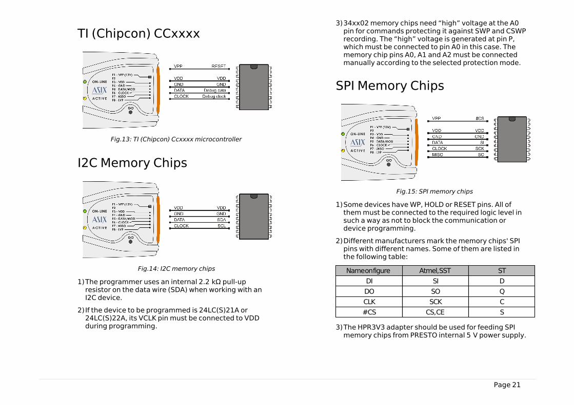
Fig.13: TI (Chipcon) Ccxxxx microcontroller
I2C Memory Chips
Fig.14: I2C memory chips
1)The programmer uses an internal 2.2 kΩ pull-upresistor on the data wire (SDA) when working with anI2C device.
2)If the device to be programmed is 24LC(S)21A or24LC(S)22A, its VCLK pin must be connected to VDDduring programming.
3)34xx02 memory chips need “high” voltage at the A0pin for commands protecting it against SWP and CSWPrecording. The “high” voltage is generated at pin P,which must be connected to pin A0 in this case. Thememory chip pins A0, A1 and A2 must be connectedmanually according to the selected protection mode.
SPI Memory Chips
Fig.15: SPI memory chips
1)Some devices have WP, HOLD or RESET pins. All ofthem must be connected to the required logic level insuch a way as not to block the communication ordevice programming.
2)Different manufacturers mark the memory chips' SPIpins with different names. Some of them are listed inthe following table:
Name on figure Atmel, SST ST
DI SI D
DO SO Q
CLK SCK C
#CS CS, CE S
3)The HPR3V3 adapter should be used for feeding SPImemory chips from PRESTO internal 5 V power supply.
Page 22
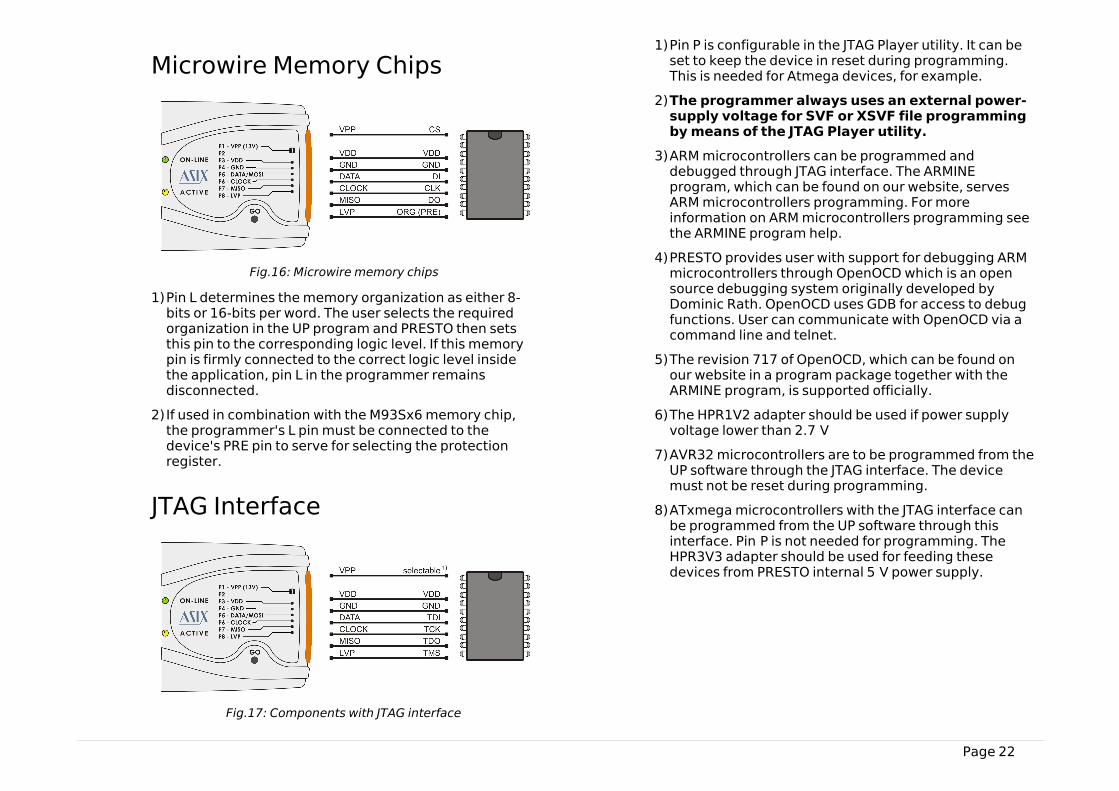
Microwire Memory Chips
Fig.16: Microwire memory chips
1)Pin L determines the memory organization as either 8-bits or 16-bits per word. The user selects the requiredorganization in the UP program and PRESTO then setsthis pin to the corresponding logic level. If this memorypin is firmly connected to the correct logic level insidethe application, pin L in the programmer remainsdisconnected.
2)If used in combination with the M93Sx6 memory chip,the programmer's L pin must be connected to thedevice's PRE pin to serve for selecting the protectionregister.
JTAG Interface
Fig.17: Components with J TAG interface
1)Pin P is configurable in the JTAG Player utility. It can beset to keep the device in reset during programming.This is needed for Atmega devices, for example.
2)The programmer always uses an external power-supply voltage for SVF or XSVF file programmingby means of the JTAG Player utility.
3)ARM microcontrollers can be programmed anddebugged through JTAG interface. The ARMINEprogram, which can be found on our website, servesARM microcontrollers programming. For moreinformation on ARM microcontrollers programming seethe ARMINE program help.
4)PRESTO provides user with support for debugging ARMmicrocontrollers through OpenOCD which is an opensource debugging system originally developed byDominic Rath. OpenOCD uses GDB for access to debugfunctions. User can communicate with OpenOCD via acommand line and telnet.
5)The revision 717 of OpenOCD, which can be found onour website in a program package together with theARMINE program, is supported officially.
6)The HPR1V2 adapter should be used if power supplyvoltage lower than 2.7 V
7)AVR32 microcontrollers are to be programmed from theUP software through the JTAG interface. The devicemust not be reset during programming.
8)ATxmega microcontrollers with the JTAG interface canbe programmed from the UP software through thisinterface. Pin P is not needed for programming. TheHPR3V3 adapter should be used for feeding thesedevices from PRESTO internal 5 V power supply.
Page 23
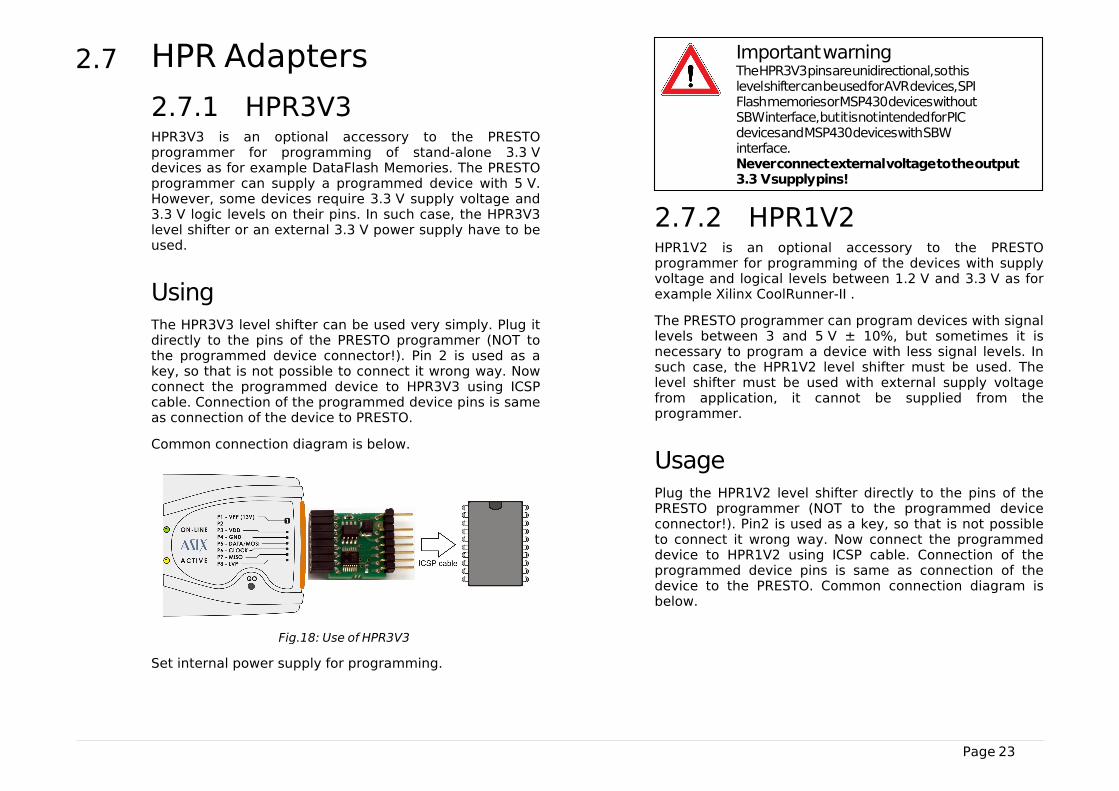
2.7 HPR Adapters
2.7.1 HPR3V3HPR3V3 is an optional accessory to the PRESTOprogrammer for programming of stand-alone 3.3 Vdevices as for example DataFlash Memories. The PRESTOprogrammer can supply a programmed device with 5 V.However, some devices require 3.3 V supply voltage and3.3 V logic levels on their pins. In such case, the HPR3V3level shifter or an external 3.3 V power supply have to beused.
UsingThe HPR3V3 level shifter can be used very simply. Plug itdirectly to the pins of the PRESTO programmer (NOT tothe programmed device connector!). Pin 2 is used as akey, so that is not possible to connect it wrong way. Nowconnect the programmed device to HPR3V3 using ICSPcable. Connection of the programmed device pins is sameas connection of the device to PRESTO.
Common connection diagram is below.
Fig.18: Use of HPR3V3
Set internal power supply for programming.
Important warning
The HPR3V3 pins are unidirectional, so thislevel shifter can be used for AVR devices, SPIFlash memories or MSP430 devices withoutSBW interface, but it is not intended for PICdevices and MSP430 devices with SBWinterface. Never connect external voltage to the output3.3 V supply pins!
2.7.2 HPR1V2HPR1V2 is an optional accessory to the PRESTOprogrammer for programming of the devices with supplyvoltage and logical levels between 1.2 V and 3.3 V as forexample Xilinx CoolRunner-II .
The PRESTO programmer can program devices with signallevels between 3 and 5 V ± 10%, but sometimes it isnecessary to program a device with less signal levels. Insuch case, the HPR1V2 level shifter must be used. Thelevel shifter must be used with external supply voltagefrom application, it cannot be supplied from theprogrammer.
UsagePlug the HPR1V2 level shifter directly to the pins of thePRESTO programmer (NOT to the programmed deviceconnector!). Pin2 is used as a key, so that is not possibleto connect it wrong way. Now connect the programmeddevice to HPR1V2 using ICSP cable. Connection of theprogrammed device pins is same as connection of thedevice to the PRESTO. Common connection diagram isbelow.
Page 24
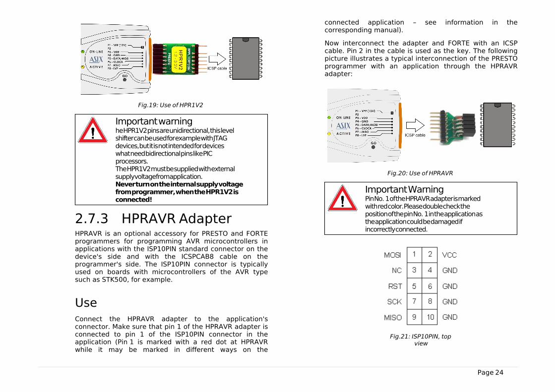
Fig.19: Use of HPR1V2
Important warning
he HPR1V2 pins are unidirectional, this levelshifter can be used for example with JTAGdevices, but it is not intended for deviceswhat need bidirectional pins like PICprocessors. The HPR1V2 must be supplied with externalsupply voltage from application. Never turn on the internal supply voltagefrom programmer, when the HPR1V2 isconnected!
2.7.3 HPRAVR AdapterHPRAVR is an optional accessory for PRESTO and FORTEprogrammers for programming AVR microcontrollers inapplications with the ISP10PIN standard connector on thedevice's side and with the ICSPCAB8 cable on theprogrammer's side. The ISP10PIN connector is typicallyused on boards with microcontrollers of the AVR typesuch as STK500, for example.
UseConnect the HPRAVR adapter to the application'sconnector. Make sure that pin 1 of the HPRAVR adapter isconnected to pin 1 of the ISP10PIN connector in theapplication (Pin 1 is marked with a red dot at HPRAVRwhile it may be marked in different ways on the
connected application – see information in thecorresponding manual).
Now interconnect the adapter and FORTE with an ICSPcable. Pin 2 in the cable is used as the key. The followingpicture illustrates a typical interconnection of the PRESTOprogrammer with an application through the HPRAVRadapter:
Fig.20: Use of HPRAVR
Important Warning
Pin No. 1 of the HPRAVR adapter is markedwith red color. Please double check theposition of the pin No. 1 in the application asthe application could be damaged ifincorrectly connected.
Fig.21: ISP10PIN, topview

Page 25
Fig.22: HPRAVR adapter diagram
2.8 Built-in ProtectionThe PRESTO programmer provides internal overcurrentprotection on the VPP and VDD pins and overvoltageprotection on the VDD pin.
PRESTO is able to detect overcurrent on the VPP or VDDpin and consequently to disable these pins but only whenPRESTO is connected to a PC and the UP program hasbeen launched. If overvoltage on VDD pin is detected awarning message is displayed.
All I/Os have their 27 Ω resistors for better shortageendurance. Inputs, where it is technically possible, areequipped with Zener diodes for better overvoltageendurance.
Any voltage peak higher than 7.5 V or any current higherthan 20 mA on any I/O can cause damage of theprogrammer.
Important warning
PRESTO must be connected to a PC and theUP program must be launched for correctfunction of internal protection.
2.9 Technical Specifications
2.9.1 Limit Values
Operatingtemperature
min. 0 °C max. +55 °C
Storage temperature min. -40 °C max. +85 °C
Maximum current onUSB
max. 370 mA
Voltage at any pin1 min. -0.5 V max. 6.5 V
Maximum current onI/O pin
20 mA
ESD protection (HBMmodel)
±4 kV contact
±8 kV air
Table 6: Limit values
2.9.2 OperatingSpecifications
Important Warning
Failure to respect these parameters maydamage the programmer or the connectedcomputer.
VDD feeding voltage supplied byprogrammer
5 V
VDD feeding voltage supplied byapplication
2.7 V to 5.5 V
Maximum current drawn fromVDD
100 mA
Maximum current drawn fromVPP
50 mA
Page 26
Maximum current drawn from I/O pin
4 mA
Allowed input voltage on pins 0 to 5.5 V
P pin output voltage 13 V or logic levels
VIL input voltage max. 0.5 V
VIH input voltage min. 2.0 V
VOL output voltage max. 0.44 V @ VDD=4.5 V
typ. 0.1 V
VOH output voltage min. 3.8 V @ VDD=4.5 V
typ. VDD - 0.1 V
Resistance to short circuiting limited2
Operating system Windows3 32/ 64-bit, Linux4
USB compatibility USB 1.1 Full Speed
USB 2.0 compatible
USB connector type B
Dimensions 112 x 64 x 22 mm
Weight 80 g
Gross weight 180 g
Table 7: Operating specifications
1 Pin VPP configured as an output has a voltage +13 V2 For more information see Built-in Protection 3 Windows XP, Windows Vista, Windows 7, Windows 8,
Windows 8.14 The UP software runs under Wine
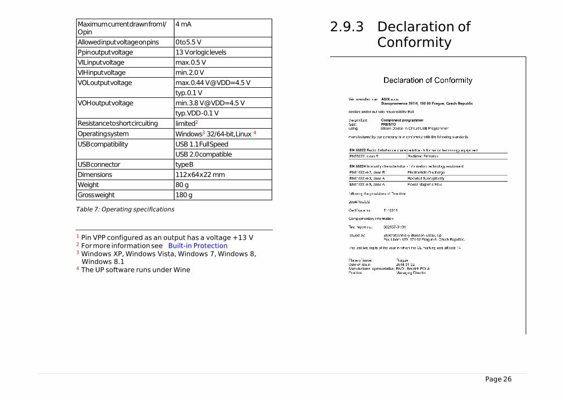
2.9.3 Declaration ofConformity

Page 27
PRESTO complies with the RoHS directive.

Page 28
3
DRIVERS
This chapter deals with driver installation and updates.
3.1 Driver Installation
3.1.1 Windows OperatingSystems
The user must have administrator rights to install and runthe UP program for the first time. Standard user rights aresufficient for further use.
PRESTO drivers are installed automatically as part of theUP program installation.
Windows 7 and laterStart with installing the UP program. Its installer installsthe USB driver for PRESTO, too. You can find the installeron the supplied CD-ROM or on the web (the preferredoption).
Once the installation is complete, connect the PRESTOprogrammer to your computer. The green ON-LINE LEDshould turn on after a few moments and the WindowsDevice Manager should present the programmer ascorrectly installed.
Older supported WindowsversionsThe driver contained in the UP installer is intended forWindows 7 and later. For older Windows operating systemversions the driver has to be downloaded fromwww.asix.net, from download section of the programmerand unpacked somewhere. After the programmer hasbeen connected, the operating system asks for the driver.In "Found New Hardware" dialog the path to theunpacked driver has to be set.
During the installation, the operating system will askwhether it should install the software, which has notpassed the Microsoft compatibility test for Windows. ClickContinue Anyway.
Fig.23: Compatibility test dialog window
The green ON-LINE LED should turn on after a fewmoments and the Windows Device Manager shouldpresent the programmer as correctly installed.
Page 29
3.1.2 LinuxThe programmer can be operated under Wine in Linux.Please find a detailed manual at http://www.asix.net/tools/supp_linux.htm
3.2 Driver UpdatingPRESTO communicates with the PC through a USB circuitproduced by FTDI www.ftdichip.com, which also developsdrivers for these circuits.
The latest drivers are always included in the UPinstallation pack.
Drivers for the Windows operating system have beenstable for a long time and therefore no further updatesare usually needed, unless additional applications usingthe FTDI circuits on the given PC so require.
However, should you need to update your driver, thesimplest way of doing so is to update the UP program.
Download the latest UP installer from the web and installthe new version without risk of losing your personalizedprogram setup data or data of your projects. The newversion will replace the original one.
Page 30
4
UP SOFTWARE
UP is a name for control software designed forprogrammers made by ASIX. The program offers manyadvanced functions and enables an operator to controlthe programming process either from the softwareinterface or remotely from the command line utilizingWindows messages and the DLL library. The program runsunder Windows or Linux (in Wine).
4.1 Abbreviations UsedMenu ➙ item bold italics followed by the arrow sign ➙ make
references to particular items in menus, names oftabs (cards) in a particular window.
4.2 InstallationInstallation is very easy. The installation program caneither be found on the CD-ROM supplied together with theprogrammer or downloaded from www.asix.net. Run theinstaller (UP_xxx_EN.EXE, where xxx represents theversion number). There is no need to close other runningapplications. The installation process takes only a fewseconds and requires you to press the Enter key a fewtimes. No modifications to the operating system takeplace during installation, i.e. no computer restart isneeded and the program can be used immediately aftercompletion (by clicking its icon, for example). After thefirst start, the program asks which language it should use(English or Czech), which programmer to work with (e.g.FORTE) and which port the programmer is connected to.
If needed, the program can be uninstalled using the Add/Remove Programs icon in the Control Panel or manually
by deleting the corresponding directory and desktopshortcut(s).
A previous program version (if it exists) does not have tobe removed before installing a newer version. Use of thelatest available version is recommended.
4.3 Device ProgrammingThe following sections describe the ways of programmingdevices and things to pay special attention to.
4.3.1 ProgrammerSelection
Before a device can be programmed, the programmerwhich will be used needs to be selected. Currently eitherFORTE or PRESTO can be chosen.
Select the programmer by going to Options ➙ Selectprogrammer or by double-clicking the programmername displayed in the top right corner of the programwindow. The following dialog window opens:
Page 31
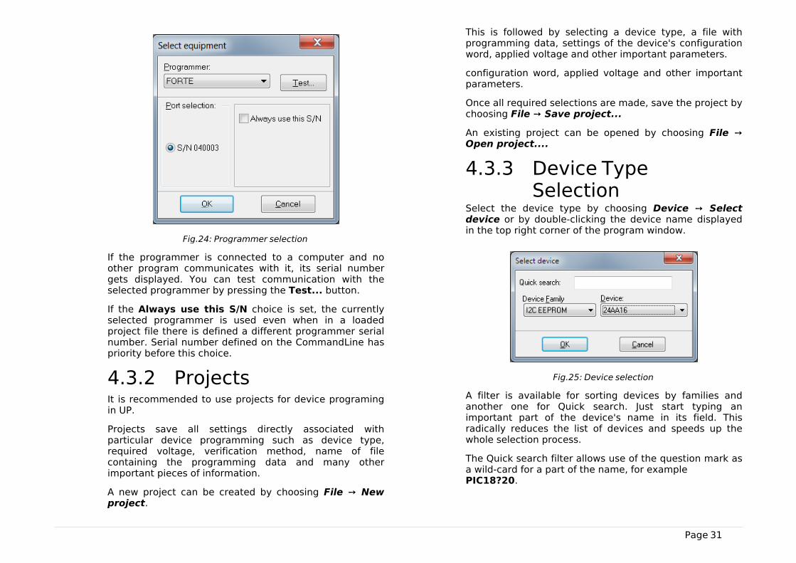
Fig.24: Programmer selection
If the programmer is connected to a computer and noother program communicates with it, its serial numbergets displayed. You can test communication with theselected programmer by pressing the Test... button.
If the Always use this S/N choice is set, the currentlyselected programmer is used even when in a loadedproject file there is defined a different programmer serialnumber. Serial number defined on the CommandLine haspriority before this choice.
4.3.2 ProjectsIt is recommended to use projects for device programingin UP.
Projects save all settings directly associated withparticular device programming such as device type,required voltage, verification method, name of filecontaining the programming data and many otherimportant pieces of information.
A new project can be created by choosing File ➙ Newproject.
This is followed by selecting a device type, a file withprogramming data, settings of the device's configurationword, applied voltage and other important parameters.
configuration word, applied voltage and other importantparameters.
Once all required selections are made, save the project bychoosing File ➙ Save project...
An existing project can be opened by choosing File ➙Open project....
4.3.3 Device TypeSelection
Select the device type by choosing Device ➙ Selectdevice or by double-clicking the device name displayedin the top right corner of the program window.
Fig.25: Device selection
A filter is available for sorting devices by families andanother one for Quick search. Just start typing animportant part of the device's name in its field. Thisradically reduces the list of devices and speeds up thewhole selection process.
The Quick search filter allows use of the question mark asa wild-card for a part of the name, for example PIC18?20.
Page 32
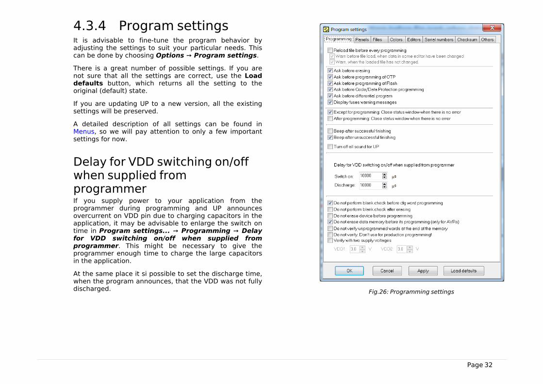
4.3.4 Program settingsIt is advisable to fine-tune the program behavior byadjusting the settings to suit your particular needs. Thiscan be done by choosing Options ➙ Program settings.
There is a great number of possible settings. If you arenot sure that all the settings are correct, use the Loaddefaults button, which returns all the setting to theoriginal (default) state.
If you are updating UP to a new version, all the existingsettings will be preserved.
A detailed description of all settings can be found inMenus, so we will pay attention to only a few importantsettings for now.
Delay for VDD switching on/offwhen supplied fromprogrammerIf you supply power to your application from theprogrammer during programming and UP announcesovercurrent on VDD pin due to charging capacitors in theapplication, it may be advisable to enlarge the switch ontime in Program settings... ➙ Programming ➙ Delayfor VDD switching on/off when supplied fromprogrammer. This might be necessary to give theprogrammer enough time to charge the large capacitorsin the application.
At the same place it si possible to set the discharge time,when the program announces, that the VDD was not fullydischarged. Fig.26: Programming settings
Page 33
Production ProgrammingSettingsIf you want to perfectly verify your production to makesure that the device is correctly programmed, you canuse the Program settings ➙ Programming ➙ Verifywith two supply voltages option and to apply thelowest and the highest voltage allowed for the device asthe limits. Some manufacturers recommend this optionfor the production programming. However, it is onlyavailable if the application is supplied with power fromFORTE.
Program settings ➙ Panels ➙ Show mass productioncounter in status bar could be a useful tool visiblymonitoring numbers of successfully and unsuccessfullyprogrammed devices. The counter can be reset in Device➙ Program ➙ Mass production ➙ Counter reset.
Program settings ➙ Serial numbers ➙ Log to file canbe used as another convenient assistant. With this optionselected, information on the programming progress ofindividual devices gets recorded (logged) in a selectedfile.
If you wish to automatically include the serial numberduring production programming, you have a great rangeof possibilities concerning what the number should looklike and where it should be positioned in the memory. Allserial number settings can be found on the Serialnumbers tab.
For further information on serial numbers see SerialNumbers.
Settings for ProgrammingDuring DevelopmentIf you are frequently changing the content of theprogramming data such as during applicationdevelopment, for example, you can simplify your work byusing the GO button, which typically serves for
programming and verification of the whole memorycontent. The function of this button is programmable andcan be set up under the Options ➙ Key shortcuts menuin the GO button section.
The use of the GO button for programming should beaccompanied by Options ➙ Program settings ➙Programming ➙ Reload file before everyprogramming option.
Options ➙ Program settings ➙ Programming ➙ Warnbefore file load, when data in some editor havebeen changed causes that a warning appears if datahave been changed in any editors and automatic filereloading option is set.
Options ➙ Program settings ➙ Programming ➙Warn, when the loaded file has not changed causesthat a warning appears if the file loaded beforeprogramming has not changed.
The following option can also be useful: Programsettings ➙ Programming ➙ After programming:Close status window if there is no error.
There are special cases when developers do not have thedevice's voltage supply pin available in an applicationpowered by an external source. In order to feed theprogrammer's output circuits, power supply from theprogrammer must be switched on in such a case and itsvoltage set at the same value as used in the application.Yet as some voltage still “sneaks” into the programmerfrom the application through the programming pins, theprogrammer “sees” that there is some voltage presentand refuses to activate its own output voltage. For such acase the following option is available: Program settings➙ Others ➙ Allow internal and external supplyvoltages collision.
WARNING: Activating this option in other situationscould damage the programmer!
Page 34
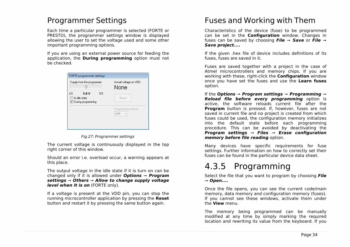
Programmer SettingsEach time a particular programmer is selected (FORTE orPRESTO), the programmer settings window is displayedallowing the user to set the voltage used and some otherimportant programming options.
If you are using an external power source for feeding theapplication, the During programming option must notbe checked.
Fig.27: Programmer settings
The current voltage is continuously displayed in the topright corner of this window.
Should an error i.e. overload occur, a warning appears atthis place.
The output voltage in the idle state if it is turn on can bechanged only if it is allowed under Options ➙ Programsettings ➙ Others ➙ Allow to change supply voltagelevel when it is on (FORTE only).
If a voltage is present at the VDD pin, you can stop therunning microcontroller application by pressing the Resetbutton and restart it by pressing the same button again.
Fuses and Working with ThemCharacteristics of the device (fuse) to be programmedcan be set in the Configuration window. Changes infuses can be saved by choosing File ➙ Save or File ➙Save project....
If the given .hex file of device includes definitions of itsfuses, fuses are saved in it.
Fuses are saved together with a project in the case ofAtmel microcontrollers and memory chips. If you areworking with these, right-click the Configuration windowonce you have set the fuses and use the Learn fusesoption.
If the Options ➙ Program settings ➙ Programming ➙Reload file before every programming option isactive, the software reloads current file after theProgram button is pressed. If, however, fuses are notsaved in current file and no project is created from whichfuses could be used, the configuration memory initializesinto the default state before each programmingprocedure. This can be avoided by deactivating theProgram settings ➙ Files ➙ Erase configurationmemory before file reading option.
Many devices have specific requirements for fusesettings. Further information on how to correctly set theirfuses can be found in the particular device data sheet.
4.3.5 ProgrammingSelect the file that you want to program by choosing File➙ Open....
Once the file opens, you can see the current code/mainmemory, data memory and configuration memory (fuses).If you cannot see these windows, activate them underthe View menu.
The memory being programmed can be manuallymodified at any time by simply marking the requiredlocation and rewriting its value from the keyboard. If you
Page 35
want to save such a modification, choose File ➙ Save,File ➙ Save as... or File ➙ Export data memory tofile....
Important warning
It is recommended to check the programmersettings and fuse settings before starting theactual programming as an error in theseparameters could damage the device or eventhe programmer.
The programming process is triggered by choosingDevice ➙ Program or by clicking the Program button.
In some devices, the system checks the Device ID (deviceelectronic signature) and the code/data protection bitsbefore launching the programming process. If the ID doesnot match the selected device type, a warning message isdisplayed.
Displaying of this warning message is frequently causedby a fault in the interconnection of the device and theprogrammer.
If things are in order, the programmer performs thefollowing operations: erases the device, checks theerasure, programs the device and checks theprogrammed device.
If only a particular memory of a microcontroller needs tobe programmed, it can be done by choosing thecorresponding item in the Device ➙ Program menu orby clicking the pull-down arrow next to the Programbutton on the button bar. Depending on the device type,the following options may be available: program code/main memory, program data (EEPROM) memory, programconfiguration memory or program all.
Differential ProgrammingThe Device ➙ Program menu offers a possibility ofdifferential programming, provided the device to beprogrammed supports it. If selected, the existing memorycontent is read first and only cells that differ are then
programmed.
Differential programming is useful for development duringwhich content of the programming data changes veryoften, but the changes are tiny. As only changed cells areoverwritten, the differential programming is advisable fordevices with a low number of writing cycles. It can also befaster than the conventional re-writing of the wholememory content.
4.4 Further FeaturesThe following section focuses on selected additionalfunctions of UP available for device programming.
4.4.1 Setting the GOButton
ASIX programmers feature a GO button, which allows theuser to trigger the programming process without acomputer mouse or keyboard.
The function of the GO button can be set under theOptions ➙ Key shortcuts menu in the GO button fieldto suit user's needs.
The UP software must be running if the user wants to usethe GO button, but may be minimized on the screen.
Additional settings associated with the GO button can befound in Settings for Programming During Development.
4.4.2 Mass ProductionThe mass production function is available under theDevice ➙ Program ➙ Mass production menu. It canalso be called up by clicking the arrow next to theProgram button on the toolbar.

Page 36
Fig.28: Mass production
The actual programming can be triggered by clicking theProgram button in the Mass production dialogwindow.
The function of this button is identical to the Program allor Program all except data memory optionsdepending on the state of the Don't program dataEEPROM checkbox in the Mass production window.
This dialog window also displays a counter of devicesprogrammed. Depending on the program settings, thecounter can also be displayed in the status bar. Forfurther information on settings see ProductionProgramming Settings.
The counter displays the number of programmed devicesin both the mass production mode and the standardmode.
Pressing the Counter reset button zeroes all the massproduction counters. This operation cannot be undone.
The programming can be launched by connectingexternal power supply (VDD).
When the "Open this form after start" setting is enabled,the form opens after program start or after project fileopen, if it is used.
4.4.3 Serial NumbersThe Serial Numbers function programs the serial numberor another sequence of characters in the selectedmemory location.
Fig.29: Serial numbers
Once the serial numbers are activated and their type setup under Options ➙ Program settings ➙ Serialnumbers, a window with the current serial number opensoffering the possibility to manually write a serial numberin the memory HEX editor, to specify where it should bewritten and if the system should proceed to the nextsequential number.
Serial numbers can be:
• Computed
The computed serial numbers must always be written inthe same selected position in the device such as thecode/main memory, data memory or an ID position, forexample. The serial number is always expected to be anumber in decimal or hexadecimal format and may becoded as a 4-bit combination (one to four characters perword) or as an ASCII character (one or two ASCIIcharacters per word). If the code/main memory is used forMicrochip microcontrollers, you can choose RETLWinstructions. Then RETLW instructions are written in thegiven address of the code/main memory together with aparameter corresponding with the serial number.
• Taken from File
A single serial number can be distributed in more thanone device memories (the serial number itself directly tothe program, the equipment address to the data memory,and the serial number again to ID positions in order to be

Page 37
able to read it from a locked device, for example).
Note: A word is understood as one memory position.
Fig.30: Serial number settings
A file for logging the programmed serial numbers can beselected under Options ➙ Program settings ➙ Serialnumbers.
The numbers themselves are logged in case of calculatedserial numbers while their labels are logged in case ofserial numbers taken from a file - see Format of Files withSerial Numbers.
Format of Files with SerialNumbersFiles containing definitions of serial numbers are text filesthat can easily be created in third-party programs. *.SN or*.TXT are recommended file extensions.
A serial number record has the following form:
[comment] label: data record, data record, ...,data record;
Semicolons are obligatory at the end of records.
• Comment is any string containing no colon ':'.Comments are optional. If a colon cannot be found inthe whole serial number record, the record is ignored(understood as a comment).
This is just a comment;
• White character is a space, tabulator or end of line(CR+LF).
• Label is a string identifying the serial number. Thisstring is compulsory. The label must not contain whitecharacters, colons or semicolons.
Data RecordA data record consists of an address and data items in achain following this address.
Each item can be written in hexadecimal form (e.g. 2100)or a numeral base in which the number is written in canbe explicitly defined.
Page 38
For example, b'10101010' means the same as h'AA',d'170' or just AA. 'A' means d'65' (ASCII character itself).
Example record for PIC16F628A:
2100 05 55 54 means to save data 05h, 55h, 54h inaddresses 00 to 02 of a data memory.
The code/main memory which stores the serial numbercan also be specified by the word “CODE.” or “PROG.” orjust “P.”.
The data memory should be specified by the word“DATA.” or “EE.” or just “E.”.
“ID” or just “I” is used for the memory of ID positions.
These words are always followed by an address inside thespecified memory.
Example:
EE.00 05 55 54 means to save data 05h, 55h, 54h inaddresses 00 to 02 of a data memory.
Notes
• * There is no specifier for the configuration memory, itwould make no sense.
dsPIC – addresses of 24-bit words are to be written in forall addresses (i.e. an internal dsPIC address of 24h is 12hhere). For a data (EEPROM) memory addresses of 16-bitwords are to be written in, i.e. as they go one by onethrough the microcontroller.
• Autonomous memory chips (I2C, SPI) have only the codememory. If a non-existent memory is specified, an erroris reported.
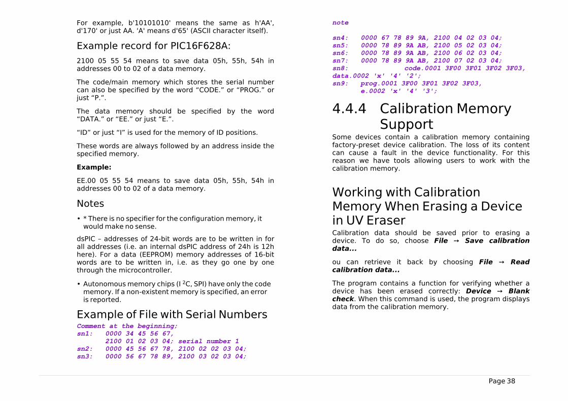
Example of File with Serial NumbersComment at the beginning; sn1: 0000 34 45 56 67, 2100 01 02 03 04; serial number 1 sn2: 0000 45 56 67 78, 2100 02 02 03 04; sn3: 0000 56 67 78 89, 2100 03 02 03 04;
note sn4: 0000 67 78 89 9A, 2100 04 02 03 04; sn5: 0000 78 89 9A AB, 2100 05 02 03 04; sn6: 0000 78 89 9A AB, 2100 06 02 03 04; sn7: 0000 78 89 9A AB, 2100 07 02 03 04; sn8: code.0001 3F00 3F01 3F02 3F03, data.0002 'x' '4' '2'; sn9: prog.0001 3F00 3F01 3F02 3F03, e.0002 'x' '4' '3';
4.4.4 Calibration MemorySupport
Some devices contain a calibration memory containingfactory-preset device calibration. The loss of its contentcan cause a fault in the device functionality. For thisreason we have tools allowing users to work with thecalibration memory.
Working with CalibrationMemory When Erasing a Devicein UV EraserCalibration data should be saved prior to erasing adevice. To do so, choose File ➙ Save calibrationdata...
ou can retrieve it back by choosing File ➙ Readcalibration data...
The program contains a function for verifying whether adevice has been erased correctly: Device ➙ Blankcheck. When this command is used, the program displaysdata from the calibration memory.

Page 39
Working With CalibrationMemory in Devices With FlashMemoryWhen these devices are erased, the content of theircalibration memory is preserved.
If you really need to erase the calibration memory forsome reason, you can do so by choosing Device ➙ Erase➙ Erase all (including calibration).
Advice
New Flash devices with a calibration memory (such asPIC12F629) contain so called 'bandgap bits', which formpart of the device calibration. These bits can be found inthe configuration word and are erased too if thecommand Device ➙ Erase ➙ Erase all(includingcalibration) is executed!
4.5 Program Controls
Fig.31: Controls of UP software
1)Title bar with the open project name or file
2)Menu
3)Toolbar
4)Currently selected programmer
5)Currently selected device
6)Programmer settings window
7)HEX editor window for code/main memory
8)HEX editor window for data memory
9)Configuration window
10)Status bar
4.5.1 ToolbarA toolbar is a panel with quick selection buttons locatedunder the program menu (see Program Controls).
If you want to remove the toolbar, simply uncheck theDisplay icons and descriptions on the toolbar buttonoptions in the Settings menu as described in Programsettings.
4.5.2 Status BarThe status bar is a panel in the bottom part of the window(see Program Controls). It presents information on theprogrammer, the device, changes to the file since the lastsaving, etc.
Individual parts of the status bar react to double-clickingand to the context menu that opens after right-clicking.
If you want to hide or re-display the status bar, chooseProgram settings ➙ Panels ➙ Display the status barin the lower part of the window.
4.5.3 MenusThe following texts describe in detail individual items inthe UP software menus.
Menu commands can be triggered with mouse by clickingon a particular menu item or from the keyboard bypressing the key together with the shortcut, i.e. the
Page 40
underlined letter in the menu.
The menu bar consists of the following menus(categories):
• File Menu
• Edit Menu
• View Menu
• Device Menu
• Options Menu
• Help Menu
File Menu
File ➙ NewKeyboard shortcut: Ctrl+N
The program creates a new empty file. If the currentlyopen file has not been saved, the program prompts theuser to save it.
File ➙ Open...Keyboard shortcut: Ctrl+O
The program opens the Windows standard dialog listingthe files saved on the disc. The supported file formats aredescribed in Appendix C: Intel-HEX File Format. Files withextensions .hex or .a43 are loaded as Intel-HEX, others asbinary. There are also filters available making it possibleto open all files as .hex or as .bin.
File ➙ Open next file...The program imports another .hex or .bin file with anoptional offset. This function is useful if the user needs toload another file into device's memory. Files withextensions .hex or .a43 are loaded as Intel-HEX, others as.bin.
For example, this command provides for merging ofseveral .hex files (e.g. bootloader + program).
File ➙ Reload actual fileKeyboard shortcut: Ctrl+R
The program re-opens (i.e. re-reads from the disc) thecurrently open file. This command is useful if you knowthat the file on the disc has changed and you want to loadthese changes into the program.
If you are using Program settings ➙ Files ➙ Doautomatic check for newer versions of actual file,the program automatically notifies the user of a change inthe currently open file and offers its reloading.
File ➙ SaveKeyboard shortcut: Ctrl+S
The program saves the file on a disc. If you want saveyour file under a different name than the current one, usethe Save As... command instead.
The program can skip unused locations of the memory.See Program settings for details.
File ➙ Save as...The program saves the open file on a disc under a newname using the Windows standard dialog.
The program can skip unused locations of the memorywhile saving or not to save certain selected locations.See Program settings for details.
File ➙ Import data memory fromfile...Using the Windows standard dialog, the program readsand imports the content of a data (EEPROM) memorysaved in a different file. This allows the user to load adata memory if this has not been saved in the same fileas the code/main memory (this concerns ATmega8microcontrollers, for example).
Important warning
Such a file, regardless of its content, is read from the zero

Page 41
address as if it contained only the data (EEPROM)memory. This means that a file generated normally by acompiler cannot be correctly read using this command.
File ➙ Open file with data memoryautomaticallyWith this option selected, the program automaticallyloads the file for the data memory alongside with loadingthe file for the code/main memory. This option is activeonly if a separate file is loaded for the data memory.
File ➙ New projectKeyboard shortcut: Shift+Ctrl+N
This command creates a new project.
It is especially advisable to use project files if youfrequently switch between programming different devicetypes or if you are using several different programmers. Aproject file contains all the corresponding settings andprovides for loading of all of them in one step.
File ➙ Open project...Keyboard shortcut: Shift+Ctrl+O
Using the Windows standard dialog, the program opensan already existing project file saved on a disc. If anadditional file had been opened together with the project,such a file opens as well.
File ➙ Save project...Keyboard shortcut: Shift+Ctrl+S
Using the Windows standard dialog, the program savesthe current project under a new name. Saving of theproject under the same name is done automatically aswell as saving the program settings, for example.
File ➙ Close projectKeyboard shortcut: Shift+Ctrl+W
The program terminates the work with the currently open
project, saves the project file on the disc and returns tothe state in which it was before the new project wasopened.
File ➙ Recent projectsThis function remembers the last 10 opened projects.Clicking the name of one of them opens the project.
File ➙ Read calibration data...Using the Windows standard dialog, the program opens afile with the calibration data and loads the data in thememory.
File ➙ Save calibration data...Using the Windows standard dialog, the program createsa file with the device's calibration data previously readfrom the device connected to the programmer. Thiscalibration data can be reloaded using Read calibrationdata if the device gets erased in the meantime.
For further information on the program's support of workwith the calibration memory see Calibration MemorySupport.
File ➙ Export to bin...This command saves binary data from the code/mainmemory, from the data memory or from ID positions in aselected file.
16 or 8 bits word width can be selected for the data to besaved.

Page 42
File ➙ ExitStandard Windows keyboard shortcut: Alt+F4 Keyboard shortcut: Alt+X
Warning
If closing of the program is forced by the TurnComputer Off command and the programdoes not receive the user's confirmation, thesystem closes it forcibly after some timewithout saving the open file or settings.
If the program is currently working with thehardware, it refuses all system's requests toturn off and can be seen as “not responding”by the system.
This command closes the program. If the open file haschanged, the program prompts the user to save thechanges.
Edit Menu
Edit ➙ Fill with value...The program fills a memory location with a specifiedvalue. This command is used especially for erasing (fillingwith ones) or zeroing (filling with zeros) a particularlocation. Yet it can be filled with any value or with randomdata.
When the Fill with value... command is called, theprogram presets the selected memory according to theactive window. If a memory location was highlightedbefore calling this command, the program presets themarked location for filling in.
A memory location can be selected by holding the Shiftkey and clicking by mouse or moving by means of thecursor keys (arrows). For further information onhighlighting a location see HEX Editor Windows.
Edit ➙ Text insert...This command saves a text in ASCII or in hexadecimalformat into a selected memory location. Ends of lines canbe coded as NULL, CR, LF or CR+LF characters.
Individual bytes can be inserted as well as saved inRETLW instructions (this applies only to the code/mainmemory working with Microchip microcontrollers).Note: Microchip PIC RETLW instruction means return witha constant value in the work register – this instruction isfrequently used for creating tables.
If the Text insert... command is called, the programpresets the selected memory and the starting cellaccording to the current window and the selected cell.
Edit ➙ Fill selected location withRETLWThis command fills the selected Microchipmicrocontroller's memory location with RETLW.
The command can be called only from an open HEXeditor. It is also available through the context menu (rightmouse click) in the editor.
A memory location can be selected by holding the Shiftkey and clicking by mouse or moving by means of thecursor keys (arrows). For further information onhighlighting a location see HEX Editor Windows.
View Menu
View ➙ Code/main memoryThis command opens or closes the code/main memoryHEX editor window. For more on HEX editors see HEXEditor Windows.
View ➙ Data memoryThis command opens or closes the data memory HEXeditor window. For more on HEX editors see HEX EditorWindows.
Page 43
View ➙ Boot memoryThis command opens or closes the boot memory HEXeditor window. For more on HEX editors see HEX EditorWindows.
View ➙ Configuration memoryThis command opens or closes the configuration memoryHEX editor window. For more on HEX editors see HEXEditor Windows.
View ➙ ConsoleThis command opens or closes the console, where the UPcan write details about programming.
View ➙ Display code/main memoryKeyboard shortcut: Alt+F10
This command displays the code/main memory HEXeditor. If it is already displayed, it moves it to the front(the editor gets focus). For more on HEX editors see HEXEditor Windows.
View ➙ Display data memoryKeyboard shortcut: Alt+F11
This command displays the data memory HEX editor. If itis already displayed, it moves it to the front (the editorgets focus). For more on HEX editors see HEX EditorWindows.
View ➙ Display configurationmemoryKeyboard shortcut: Alt+F12
This command displays the configuration memory HEXeditor. If it is already displayed, it moves it to the front(the editor gets focus). For more on HEX editors see HEXEditor Windows.
Device Menu
Device ➙ ProgramKeyboard shortcut: Shift+F5
This command opens a sub-menu with programmingoptions. Some items may be inaccessible for certaindevice types.
▸ Program allKeyboard shortcut: F5
This command erases the device, checks the erasure,programs it and verifies the programming result in thewhole device. The Device ID check and the Code/DataProtection check are performed prior to this operation.The behavior of this command is influenced by theprogram settings - see Program settings.
▸ Program all except data memoryA keyboard shortcut can be assigned in Options ➙ Keyshortcuts.
This command works the same as Program all with theexception that it does NOT erase, program or verify thedata memory.
Devices without a data memory do not have thiscommand available and their programming is done usingthe Program all command.
This command cannot be used in some cases that useCode or Data Protection. For these, the program offersthe command Erase whole device and program alsodata memory (with data currently in the editor).
▸ Program code/main memoryA keyboard shortcut can be assigned in Options ➙ Keyshortcuts.
This command erases the code/main memory, checks theerasure, programs and checks the programming result.

Page 44
▸ Program data memoryA keyboard shortcut can be assigned in Options ➙ Keyshortcuts
This command erases the data memory, checks theerasure, programs and checks the programming result.
▸ Program configuration memoryA keyboard shortcut can be assigned in Options ➙ Keyshortcuts
This command programs the configuration memory andID positions (if device contains them) and checks theprogramming result
▸ Program differentiallyKeyboard shortcut: Ctrl+F5
This command programs the device applying thedifferential method. This means that it reads the deviceand programs only those cells the content of which differsfrom the editor.
This command is available only for those devices thatsupport such treatment (not all devices do).
If a device has the Code/Data Protection active,differential programming makes no sense. The programperforms complete programming instead, includingdevice erasure.
▸ Differential program data memoryA keyboard shortcut can be assigned in Options ➙ Keyshortcuts
This command programs the data memory applying thedifferential method. Its function is identical withdifferential programming of the code/main memory.
This command is available only for those devices thatsupport such treatment (not all devices do).
If a device has the Code/Data Protection active,differential programming makes no sense. The program
performs complete programming instead, includingdevice erasure.
Differential programming of a data memory should beused for AVR microcontrollers if the user needs toreprogram the data memory only without previouslyerasing the device.
▸ Mass ProductionA keyboard shortcut can be assigned in Options ➙ Keyshortcuts
This command opens a window for easy programming ofseveral identical devices with the same or very similarprogram(s) (except their serial numbers and the like). Forfurther information see Mass Production.
Device ➙ ReadKeyboard shortcut: Shift+F6
This command opens a sub-menu with device readingoptions. Some of them may be not available for certaindevice types.
▸ Read allKeyboard shortcut: F6
This command reads the content of the whole device.
▸ Read all except data memoryA keyboard shortcut can be assigned in Options ➙ Keyshortcuts
This command reads the content of the whole deviceexcept the data memory.
▸ Read code/main memoryA keyboard shortcut can be assigned in Options ➙ Keyshortcuts
This command reads the content of the code/mainmemory.

Page 45
▸ Read data memoryA keyboard shortcut can be assigned in Options ➙ Keyshortcuts
This command reads the data (EEPROM) memory.
▸ Read configuration memoryA keyboard shortcut can be assigned in Options ➙ Keyshortcuts
This command reads the configuration memory and IDpositions (if device contains them).
Device ➙ VerifyKeyboard shortcut: Shift+F7
This command opens a sub-menu with device memorycontent verification options. Some of them may be notavailable for certain device types
▸ Verify allKeyboard shortcut: F7
This command compares the content of all devicememories with the current content of HEX editors.
▸ Verify all except data memoryA keyboard shortcut can be assigned in Options ➙ Keyshortcuts
This command compares the content of all devicememories except its data memory with the currentcontent of HEX editors.
▸ Verify code/main memoryA keyboard shortcut can be assigned in Options ➙ Keyshortcuts
This command compares the content of the code/mainmemory with the current content of code/main memory'sHEX editor.
▸ Verify data memoryA keyboard shortcut can be assigned in Options ➙ Keyshortcuts
This command compares the content of the data memorywith the current content of data memory's HEX editor.
▸ Verify configuration memoryA keyboard shortcut can be assigned in Options ➙ Keyshortcuts
This command compares the content of device'sconfiguration memory and ID positions (if device containsthem) with settings in the Configuration window.
Device ➙ EraseKeyboard shortcut: Shift+F8
This command opens a sub-menu with device memoryerasing options.
Erasure verification (blank check) is automaticallyperformed after each erasing. This verification can beskipped by choosing Options ➙ Program settings ➙Programming ➙ Do not perform blank check aftererasing. This can save time with some devices.
▸ Erase allKeyboard shortcut: F8
This command erases the whole device.
▸ Erase code/main memoryA keyboard shortcut can be assigned in Options ➙ Keyshortcuts
This command erases the code/main memory. It cannotbe used if Code/Data Protection is active.
Page 46
▸ Erase data memoryA keyboard shortcut can be assigned in Options ➙ Keyshortcuts
This command erases the data memory and verifies it. Itcannot be used if Code/Data Protection is active.
Device ➙ Blank checkKeyboard shortcut: Shift+F9
This command opens a sub-menu with device erasureverification options. Some of them may be not availablefor certain device types.
▸ Blank check allKeyboard shortcut: F9
This command verifies whether the device is correctlyand completely erased.
▸ Blank check all except data memoryA keyboard shortcut can be assigned in Options ➙ Keyshortcuts
This command verifies whether the device except thedata memory has been correctly erased.
▸ Blank check of code/main memoryA keyboard shortcut can be assigned in Options ➙ Keyshortcuts
This command verifies whether the code/main memory iscorrectly erased.
▸ Blank check of data memoryA keyboard shortcut can be assigned in Options ➙ Keyshortcuts
This command verifies whether the data memory iscorrectly erased.
▸ Blank check of configuration memoryA keyboard shortcut can be assigned in Options ➙ Keyshortcuts
This command verifies whether the configuration memoryand ID positions (if device contains them) are correctlyerased.
Device ➙ Select deviceKeyboard shortcut: F4
This dialog allows you to select a device type to beprogrammed. Some memory types need to have theirdata organization selected after the device typeselection.
Only devices supported by the currently selectedprogrammer are displayed in the dialog window. If youwant to select a device not supported by the currentprogrammer, select a different programmer type first.
For further information on selecting a device see DeviceType Selection.

Page 47
Options MenuKeyboard shortcut: Shift+F10
The Options menu holds all the possible settings of theUP program. There is a great number of settingparameters. If you are not sure that all settings arecorrect, you may use the Load defaults button, whichreturns all the settings to the initial (factory) state.
Advice
Program settings ➙ Load defaults button renews the state ofall settings on all tabs, i.e. even the color settings, for example.
Options ➙ Program settings ➙ProgrammingKeyboard shortcut: Shift+F10
This tab provides for setting all the general programmingparameters.
Settings concerning the programmer and thecommunication port are described in ProgrammerSelection.
A special Device ➙ Select device window is available forsetting the device type.
▸ Reload file before every programmingThe program reads the current file with programmingdata from the disc before each and every request toprogram a device if this option is checked.
If the use of serial numbers is also activated requestingreading the current file prior to programming, then thefile is read first and only then is the current serial numberwritten.
▸ Warn before file load, when data insome editor have been changedWhen before load of the file before programming it isfound that data in some editor have been changed, theprogram shows a warning.
▸ Warn, when the loaded file has notchangedProgram shows a warning, when the content of theloaded file has not changed from the previousprogramming.
▸ Ask before erasingWith this option checked, the program asks for userconfirmation before erasing a device.
▸ Ask before programming of OTP / Flash/ Code/Data Protection / differentialA set of options determining which user confirmationdialogs will or will not be displayed by the program.
The program asks just once except the Code/DataProtection programming. If the program needs to askthe user for additional information before actualprogramming (such as Device has Code or DataProtection. Do you want to erase it entirely?), itdoes not ask for further programming confirmation afteranswering the first dialog.
▸ Display fuse warning messagesThe user can choose if warning messages should bedisplayed for some fuses. It is recommended to leave thisoption on.
▸ Except for programming: Close statuswindowThis option closes the status window if no error occursduring erasing, blank check, programming verificationand reading.
Page 48
▸ After programming: Close statuswindowThis option closes the status window if no error occursduring programming and the subsequent verification.
▸ Beep after successful finishingWith this option active, the program calls up the standardWindows system beep if the operation (such as erasing,programming, etc.) went smoothly.
▸ Beep after unsuccessful finishingWith this option active, the program calls up the standardWindows system beep if an error or warning occurs duringthe operation (such as erasing, programming, etc.).
▸ Turn off all sound for UPWith this option on, the program does not produce anysounds.
▸ Delay for VDD switching on/off whensupplied from programmerThis option is important for programming PCB-placeddevices via an ICSP cable. It determines the length of thedelay after voltage is connected to or disconnected froma device.
Both PRESTO and FORTE feature an overcurrentprotection. This means that a test for excessive current ofapproximately 100 mA in power supply voltage isperformed after connecting power to the device andexpiration of the delay time set in Switch on.
Similarly the delay time set in Discharge specifies howlate after switching the power supply off a check shouldbe performed if no voltage is present any longer at thepin.
If a blocking capacitor is connected to the device's powersupply pins (recommended), the voltage at the pinchanges more slowly. This could cause problems duringprogramming, but they can be eliminated by prolongingthe charging and discharging time.
Too long a time increases the risk of damaging the deviceif connected incorrectly while too short a time couldcause programmer's circuits to still detect excessivecurrent flowing to the application's capacitors. A formulafor an approximate determination of the necessary timecan be found in Appendix B: Use of ICSP.
▸ Do not perform blank check before cfgword programmingMost rewritable devices can overwrite the configurationword without erasing the whole device content. Skippingthe blank check of the configuration word utilizes thispossibility, i.e. the program ignores the not erased word.
This option does not apply to the whole-deviceprogramming in which the device is erased completely. Itconcerns only the configuration word and its overwriting.
▸ Do not perform blank check aftererasingThis option speeds up the programming process and isuseful especially for debugging. The danger is that anincorrectly erased device is subsequently incorrectlyprogrammed and the fault only gets detected later. Onthe other hand, a device is erased incorrectly only once inseveral hundred attempts.
▸ Do not erase device beforeprogrammingThe device is not erased before programming.
▸ Do not erase data memory before itsprogrammingThis option only concerns programming of Atmel AVRdevices e.g. ATmega8. Data memory of this familydevices does not require to be erased beforeprogramming. If this option is not activated, whole devicewill be erased before programming.

Page 49
▸ Do not verify unprogrammed words atthe end of the memoryIf there is a location at the end of the code/main memorycontaining only default values, it is not verified.
This option speeds up the verification of the programmedmemory as the content of the “empty” memory at its endusually does not matter.
▸ Do not verifyThis option completely switches off the verification of aprogrammed device. Such off-switching can radicallyspeed up the programming process during development.
This option must not be activated for production ascorrectness of the programmed content would not beguaranteed.
▸ Verify with two supply voltagesThis option is available only for FORTE and only for theinternal power supply from the programmer. It allows youto perform the verification at two different power supplyvoltages defined by the user.
Some device manufacturers recommend to verify thecontent after production programming at two differentvoltages corresponding with the approved range of thedevice's power supply voltages.
Options ➙ Program settings ➙PanelsKeyboard shortcut: Shift+F10
This part of the Options menu allows you to alter theapplication's appearance. The user can set where andhow some control components are to be displayed.
▸ Display selected device on toolbarIn addition to the status bar, the selected device is alsodisplayed in the toolbar.
▸ Display selected programmer ontoolbarIn addition to the status bar, the selected programmer isalso displayed in the toolbar.
▸ Display the status bar in the lower partof the windowThis option determines whether the status bar is to bedisplayed or not.
▸ Display icons on toolbar buttonsIcons of individual tools are displayed in the toolbar.
▸ Display descriptions on toolbar buttonsTool names are displayed next to individual tools in thetoolbar.
If the Descriptions on toolbar buttons to the rightoption is used, the total toolbar height is reduced to ahalf.
▸ Show mass production counter instatus barThis option displays the mass production counter in thestatus bar. The counter shows the number of devicesprogrammed and the number of devices programmedsuccessfully.
If you use the Count all actions option, the counterincludes all actions performed with the device (such asreading, erasing, data memory programming, etc.).
Show values description displays explanatory notes toindividual counter items for easier understanding.
If you want to exclude operations that triggered awarning from the correct operations, use the If actionends with warning assume as erroneous option.
The choice Reset counters on project open causes,that the counters are reset on any project file load,including automatic project load during program start.
Page 50
Counter style allows you to choose whether the countershould display the good/bad or good/total figures.
The Counter reset, button can be used for zeroing thecounters while their initial values can be set in the Presetcounter values fields.
Options ➙ Program settings ➙ FilesKeyboard shortcut: Shift+F10
This tab holds all the settings for reading data from andsaving data to files.
▸ File save styleThe File save style panel offers the possibility not toalways save all areas of all editors in the file, but ratheronly some. UP then asks questions based on the savingstyle settings before saving different project editors.
▸ Automatically check for newer versionsof actual fileThis option helps especially in debugging a program. Theprogram re-loads the file if it detects a change in the filemodification date.
▸ Check device type when loading .hexfileIf the device type has been saved in the correspondingIntel-HEX file and it does not agree with the currentlyselected device type, the program points out thisdiscrepancy.
▸ Save device type into .hex fileThe program adds one more line below the end of filecommand specifying the type of device for which the fileis being saved.
Such a modified file does not comply with the Intel-HEXformat, but most programs working with the Intel-HEXformat ignore this line.
For further information about the Intel-HEX format see
Appendix C: Intel-HEX File Format.
▸ Warn when loaded file does notcontain CFG memory dataIf the file does not contain configuration memory dataand the data are expected for the chosen device, awarning message is displayed.
▸ Binary file loading and saving styleThis panel provides for the setting of how .bin files are tobe loaded and saved if a device with more than one byteper word is selected.
Available options are: the program always asks beforeloading or saving a .bin file (Ask if to load/save .bin asBig or Little Endian), or without asking, the programalways loads files as Little Endian (Never ask, load/saveas Little Endian) or as Big Endian (Never ask, load/save as Big Endian).
▸ Save unused locations to .hex fileIf not all positions are saved, the final file is smaller, but itcan cause difficulties as a cell is considered an “emptyposition” if it contains only ones (e.i. FFFh, 3FFFh, etc.).Yet this could be a meaningful instruction (3FFFh isMicrochip PIC addlw -1 instruction, for example).
As UP always saves files by larger blocks, (by eight orsixteen bytes), the danger of losing an instruction by suchsaving is rather small in reality.
If you use memory initialization prior to loading a .hex file(which is recommended), even a program loaded from areduced .hex file will be correctly programmed as themissing instructions are created “automatically”.
▸ Clear code/main / data memory / IDpositions before file readingThis location is filled with ones and only then a file isloaded. This way all positions that are not saved in the.hex file get erased.
This option is also important if no “empty” locations are
Page 51
saved in the .hex file (see ▸ Save unused locations to .hexfile).
▸ Erase configuration memory before filereadingWith this option activated, the configuration memory isinitialized before a file for code/main memory is loaded.
If no fuses are saved in the file, it is recommended todeactivate this option. At the beginning of the work, theuser can set the content of the configuration memory andthen the fuses do not have to be set again if the file isrepeatedly loaded.
▸ Read data memory not from the file butfrom the deviceIf you want to make sure that the content of the datamemory does not get overwritten, use the ▸ Program allexcept data memory option. If, however the ▸ Program alloption is selected by accident (by unintended pressing ofthe GO button, for example), the content of the datamemory would be erased.
For such cases, this option of Read data memory notfrom the file but from the device is available. Theprogram fills in the given location with the memorycontent of the device connected to the programmer.
Advice
This option could cause unexpected actions during workwith the programmer such as switching the application onor starting the UP program.
▸ Read ID positions not from the file butfrom the deviceIf you want to preserve the content of the ID positions,use the Read ID positions not from the file but fromthe device option. The program fills in the given locationwith the memory content of the device connected to theprogrammer before starting the programming itself.
Advice
This option could cause unexpected actions during workwith the programmer such as switching the application onor starting the UP program.
▸ Project saving styleThis panel allows you to set how projects should be savedwhen exiting UP. Available options are: saveautomatically, ask before saving or keep the original file(i.e. do not save).
Options ➙ Program settings ➙ColorsKeyboard shortcut: Shift+F10
This is where you can change and save colors of HEXeditors so that they suit your needs and your aestheticpreferences.
A front color, a background color and a font can beselected for all the listed text segments.
Options ➙ Program settings ➙EditorsKeyboard shortcut: Shift+F10
▸ Code/main memory editor: show wordsas bytesIndividual words can be displayed by bytes in case ofdevices with 16-bit-long words.
▸ Code/main memory editor 8 wordswideThis option narrows the editor from the original sixteencells down to eight. The option is suitable especially forsmall monitors. It can change automatically when adifferent device type is selected.
The same option can be set for others memories:
Page 52
▸ Data memory editor 8 words wide
▸ Boot memory editor 8 words wide
▸ Show only the lowest byte of word inASCIIWhen this option is activated, the program shows theASCII translation of only the lowest byte of word, whichcan be useful especially for PIC MCUs.
▸ Mask ID positions while reading fromdevice, from file, etc.Some manufacturers' specifications recommend savingonly masked data (with only four bits usable) in IDpositions. With this option activated, the program alwaysapplies this bit mask when reading ID positions fromdifferent sources.
▸ Mask ID positions during direct userinputWith this option activated, the program applies the bitmask to each user-modification of ID positions. For furtherinformation see ▸ Mask ID positions while reading fromdevice, from file, etc..
▸ Configuration memory editor: show cfgword instead of fusesThis option is recommended for advanced users only. It isnot saved in the UP configuration file for safety reasons.
Direct editing of fuses is understood as direct writing of aconfiguration word value in the hexadecimal form.
When a “non-translatable” configuration word is entered,the program leaves the unrecognized items unchangedunless the user changes them him/herself. This typicallyconcerns CP fuses having several bits but only twovalues.
Options ➙ Program settings ➙ SerialnumbersKeyboard shortcut: Shift+F10
For further information on working with serial numberssee Serial Numbers.
▸ Serial numbersThis tab allows you to choose whether serial numbers areto be used and if so then whether they should be readfrom a file or computed and whether they should beautomatically written to the corresponding location.
▸ Prepare S/N before programmingThis option prepares a serial number in the selectedmemory location before the actual device programming.
▸ Find successor after programmingOnce one programming procedure is successfullycompleted, the system proceeds to the following serialnumber. If this option is not activated, it is still possible toproceed to the following number manually by clicking theNext button on the Serial numbers tab – see SerialNumbers.
▸ Prepare S/N after programmingThis option causes that a serial number is prepared in theselected memory location after the device programming.
▸ Serial number intervalThis defines by what value the following serial numberwill be larger or smaller.
▸ Log to fileBy activating this option and by selecting a log file in thefield, information about correctly and incorrectlyprogrammed devices as well as the programming time issaved in the selected file.
For further information see Serial Numbers.
Page 53
▸ Serial number length (the number ofcharacters)This field determines how many characters the serialnumber can hold. For example, 4 characters provide forthe serial numbers 0001 to 9999 in base 10 (i.e. indecimal form).
▸ Number baseThis option defines the base of the serial numbercharacters. Base 10 and base 16 are available (i.e. thedecimal and hexadecimal forms).
▸ Code as ASCIIWith this option activated, serial numbers are legible asASCII characters.
▸ Initial serial numberThis field defines the initial value from which serialnumbers are to be computed.
▸ Next S/NThis field defines how the following serial number is to begenerated.
If The same is selected, the serial number does notchange. If One interval higher is selected, the followingnumber will be larger by the value of ▸ Serial numberinterval while if One interval lower is selected, it willreduce by that value.
The Generated LSFR option generates the numbers in apseudo-random sequence. This means that the sequencewill always be the same if the same Initial serialnumber and the same Serial numbers step is used.
▸ DestinationThis panel determines the memory location in which theserial numbers are to be stored. Code/main memory,data memory and ID positions are available asoptions.
▸ Hexadecimal address of first wordThis address defines where the first word of the serialnumber is to start in the selected memory type.
▸ Fill with RETLW instructionIndividual words of the serial number can be filled withRETLW instruction in Microchip microcontrollers. Thisoption is available only if the serial number is located inthe code/main memory.
▸ Characters per wordThis panel determines how many serial numbercharacters form one word. Options of 1 to 4 charactersper word are available.
▸ SequenceThis panel sets how individual serial number charactersand words are to be ordered.
For example, if you have a base 10 serial numberconsisting of four characters organized as 2 charactersper word and you are working let's say with 1234 as theserial number, it will be saved in the following ways:
HiLo hilo: 12 34 hilo HiLo: 34 12 LoHi lohi: 21 43 lohi LoHi: 43 21
Options ➙ Program settings ➙Checksum▸ Show checksum in status barAfter enabling of this setting the checksum of the codememory will be shown on the status bar.
Note: Doubleclick on the checksum value in the status barwill cause the value recalculation.
Page 54
▸ Checksum algorithmUsing this choice the checksum calculation algorithm canbe chosen.
Options ➙ Program settings ➙OthersKeyboard shortcut: Shift+F10
▸ Update check settingsHere you can set if the program should ask for yourpermission to connect to the Internet and check forupdates upon each start or not.
For further information see Updating UP.
▸ Allow internal and external supplyvoltages collision
Warning
A collision of power supply voltages candamage the programmer or the application!
If you approve the collision of supply voltages, it allowsthe programmer to connect its internal voltage to pinVDD at times when it can already see a voltage presentthere. This could damage both the programmer and/orthe application being programmed.
This option has been included for very specific cases. Oneof them can be a request to program an application,which does not have any VDD pin. Then the applicationmust be powered from its own source but theprogrammer's output buffers must be powered from theUSB. Yet as the voltage at the application's data signals“sneaks” through the protective diodes into the outputsection of the programmer, the programmer can see acertain small voltage present at VDD and refuses toconnect its own internal voltage to it.
▸ Do not show warning if internal 5 V isswitched on with 3.3 V device
Warning
High a voltage at the device can damage theprogrammer or the application beingprogrammed.
This option can be used to suppress the warning if ahigher voltage is switched on at the VDD output than thevalue allowed for the particular device.
If there is a voltage convertor integrated in theapplication between the device being programmed andthe programming interface, it might be useful to use thisoption of programing at a higher voltage than what thedevice has been designed for.
This option is available only for PRESTO.
▸ Allow to change supply voltage levelwhen it is onIn order to protect the application connected to FORTEfrom damage, it is typically forbidden to change theoutput voltage level if the voltage is currently connectedto the application. After activating this option, the outputvoltage can be changed at any time within the range thatthe device being programmed can cope with.
Options ➙ Select programmerSettings concerning the programmer and thecommunication port are described in ProgrammerSelection.
Options ➙ Language selection...Keyboard shortcut: Ctrl+L
A file with a different language localization can beselected using the Windows standard dialog. This meansthat one program installation can easily switch betweendifferent user-interface languages.
Page 55
Options ➙ Keyboard shortcuts...Keyboard shortcut: Ctrl+K
Using this dialog window you can define or changekeyboard shortcuts for most commands the programmeris capable of performing.
This window also provides for setting the requiredbehavior of the GO button.
Help Menu
Help ➙ Help on programKeyboard shortcut: F1
This command opens the help that you are are justreading.
Help ➙ List of supported devicesThis command displays a list of devices currentlysupported by the latest version of UP.
Help ➙ Check Internet for updatesThe program connects to the Internet and checks if youare using the latest version.
Help ➙ ASIX websiteThis command opens www.asix.cz, the website of ASIXs.r.o. where you can find the latest drivers and manualsfor ASIX products.
Help ➙ AboutBasic information on the program and a contact totechnical support.
4.5.4 Programmer SettingsWindow
All important settings concerning the programmer andthe applications to be programmed are displayed in theprogrammer settings window.
The window appearance changes in accordance with theselected programmer and device.
FORTE Programmer SettingsWindowPower supply from the programmerThis trackbar allows the user to set the voltage levelsupplied to the application by the programmer.
In idle stateIf this option is checked, the programmer supplies powerto the application even when not programming.
During programmingIf this option is checked, voltage from the programmerwill be used during programming.
ResetThis button allows you to switch levels on the device'sreset pin between the level required for reset and highimpedance.
Reset is active if voltage is present on the power supplypin.
Settings Associated with PICMicrocontrollers
Page 56
▸ Programming method• HVP Traditional programming will be applied using a
voltage of 8 V to 13 V at pin P.
• LVP Programming utilizing the microcontroller's LVP pinwill be applied; only logical values of 0 or 1 are presentat programmer's pin P.
▸ Use PEProgramming utilizing the Use PE option can be appliedto PIC24 and dsPIC33 devices. PE stands for ProgrammingExecutive and it is a programming method frequentlyproving to be faster.
Boot memory programmingThis allows to select the boot memory region to beprogrammed or checked.
Settings Associated with AVR and8051 MicrocontrollersOscillator frequencyAn external oscillator or a functional internal oscillatormust be connected in the course of AVR microcontrollerprogramming. The frequency setting must match thefrequency at which the device's oscillator is reallyrunning, after eventual dividers. The maximum speed ofcommunication with the microcontroller then depends onthe frequency of this oscillator.
Faster Programming with Slow ClockIf this option is active, once the device is erased, thefuses are programmed at the maximum frequency of theinternal oscillator. This allows the programmer tocommunicate with the device at a faster speed. At theend of programming, the required value of thecommunication memory including the clock speed isprogrammed.
This option has its effect only if the whole device isprogrammed.
Inverse ResetWith this option activated, the programmer generates aninverse reset signal.
This option is appreciated if the application includes areset circuit that needs an inverse signal at the inputcompared to the output signal sent to the microcontroller,and if the programmer is connected via this reset circuit.
HVPIf this option is checked, the programmer uses the “high”voltage at pin P for communication with the device.
This allows you to program a device with the externalRESET signal switched off.
Settings Associated with I2CMemory ChipsI2C Bus SpeedSelect the maximum possible speed of the I2C bus. Theprogrammer switches on the internal pull-up of 2.4 kΩwhile working on the I2C bus.
I2C Memory AddressSelect the address of the I2C memory on the bus.
PRESTO Programmer SettingsWindowIn idle stateIf this option is checked, the programmer supplies powerto the application even when not programming.
During programmingIf this option is checked, voltage from the programmerwill be used during programming.

Page 57
Settings Associated with PICMicrocontrollersMCLR Pin ControlThe logical value present at pin P1 (VPP) can becontrolled by the Run, Stop, Tristate and Reset buttonsin the idle state if a voltage is present.
The Reset button generates a resetting pulse.
Programming Method• HVP Traditional programming is applied with 13 V
present at VPP.
• LVP Programming utilizing microcontroller's LVP pin isapplied, only logical values of 0 or 1 are present atprogrammer's pin P.
Algorithm Programming• Auto An algorithm is selected according to the voltage
currently present at VDD.
• Ucc=5 V The algorithm for fast 5 V programming isused.
• Ucc=2.7 to 5.5 V The algorithm for slow programmingis used with the benefit of working at all power supplyvoltages.
Use PEProgramming utilizing the Use PE option can be appliedto PIC24 and dsPIC33 devices. PE stands for ProgrammingExecutive and it is a programming method frequentlyproving to be faster
Boot memory programmingThis allows to select the boot memory region to beprogrammed or checked.
Settings Associated with AVR and8051 MicrocontrollersOscillator FrequencyAn external oscillator or a functional internal oscillatormust be connected in the course of AVR microcontrollerprogramming. The frequency setting must match thefrequency at which the device's oscillator is reallyrunning, after eventual dividers. The maximum speed ofcommunication with the microcontroller then depends onthe frequency of this oscillator.
Faster Programming with Slow ClockIf this option is active, once the device is erased, thefuses are programmed at the maximum frequency of theinternal oscillator. This allows the programmer tocommunicate with the device at a faster speed. At theend of programming, the required value of thecommunication memory including the clock speed isprogrammed.
This option has its effect only if the whole device isprogrammed.
Inverse ResetWith this option activated, the programmer generates aninverse reset signal.
This option is appreciated if the application includes areset circuit that needs an inverse signal at the inputcompared to the output signal sent to the microcontrollerand if the programmer is connected via this reset circuit.
HVPIf this option is checked, the programmer uses the “high”voltage at pin P for communication with the device.
This allows you to program a device with the externalRESET signal switched off.
Page 58
Settings Associated with I2CMemory ChipsI2C Bus SpeedSelect the maximum possible speed of the I2C bus. Theprogrammer switches on the internal pull-up of 2.2 kΩwhile working on the I2C bus.
I2C Memory AddressSelect the address of the I2C memory on the bus.
4.5.5 HEX Editor WindowsHEX editors are used for displaying the content of amemory chip to be programmed.
Different colors are used in HEX editors to differentiatebetween states of different cells to make it easy to seewhich cells have been read from a file, which have beensuccessfully programmed, etc.
Colors may be user-assigned. This is especiallyrecommended for workstations with displays/screensdisplaying only a limited number of colors.
Selecting an AreaAn area can be selected in a HEX editor by holding theShift key down and pressing the cursor keys (i.e. arrows).
Once a required area is selected, it can be filled with arequired value. The values can also be filled with RETLWinstruction. These options are available in the contextmenu (opens by mouse right-click).
Code/Main Memory EditorMenu: View ➙ Display code/main memory
Keyboard shortcut to open the window: F10Keyboard shortcut to close the window: Esc
The code/main memory editor displays the code/mainmemory content or the content of the memory itself incase of serial EEPROM chips (24xx, 93xx,...).
Data Memory (EEPROM) EditorMenu: View ➙ Display data memory
Keyboard shortcut to open the window: F11Keyboard shortcut to close the window: Esc
The data memory editor is used for displaying the contentof the additional memory in some devices (typicallyEEPROM).
Not all devices have an additional memory. This meansthe editor may not be available for some devices.
Configuration Memory EditorMenu: View ➙ Display configuration memory
Keyboard shortcut to open the window: F12 Keyboard shortcut to close the window: Esc
The configuration memory editor displays settings thatare to be programmed in a device, but are not part of anyof the above memory types.
The configuration memory editor content depends on theselected device type. It is necessary to get acquaintedwith the device's data sheet in order to get a closerexplanation of individual options in this window.
Not all devices need configuration data. This means theeditor may not be available for some devices.
Tips for Advanced UsersEven though the configuration memory may be presentedas a set of settings, in reality it is nothing more than amemory that can be approached cell by cell. Due to this,it is possible to display the memory in this way.

Page 59
This can be achieved by activating Options ➙ Programsettings ➙ Editors ➙ Configuration memory editor:show cfg word instead of fuses option or by double-clicking the configuration memory window.
The device's ID positions (do not mistake for Device ID)can also be found in the configuration memory window. IDpositions can be programmed with values identifying thedevice, such as the serial number, for example. IDpositions can always be read - even if the device is lockedagainst reading.
According to the recommendation of the Microchip, IDpositions should not be programmed with any value; onlya certain number of bits (typically 4) should carry data foridentification while other bits should be programmed withthe default value.
This can be achieved by activating Options ➙ Programsettings ➙ Editors ➙ Mask ID positions....
4.6 Running UP fromCommand LineThe UP program can alternatively be controlled from thecommand line.
The program itself makes sure that it always runs in oneinstance only (with one class name). Should a secondinstance (with the same class name) be started,parameters from the command line are transferred to thefirst instance for execution. Up can be started in moreinstances using different class name, see /wnd in List ofParameters.
4.6.1 List of ParametersUP.EXE [{/ask | /q}][{/e File_with_eepromm.hex | [/noe]}] [{/p |[/pdiff]| [/o]} File.hex | File.ppr] [/part device_name] [/eeonly][/erase][/w[nd]up_window_class] [/cfg] [/devid] [/blank] [/verify File] [/read File] [/s SN_programmer's][/progname name] [/noboot] [/boot] [/code] [/
getpartrev]
Legend
• Text presented here in bold is to be keyed in in thecommand line exactly as printed here.
• Text presented here in italics is to be replaced by thecorresponding parameter. For example, file_nameshould be replaced with the real name of a file to beopened.
• Text in braces {} separated by the | sign represents aselection of one of the presented options. For example,{ A | B } means “choose either A or B”.
• Text in square brackets [] presents an optionalparameter – it can be keyed in but does not have to.
• Text in quotation marks “ ” is a mnemonic.
/ask To be used linked with /p. The programalways asks if it is to continue beforelaunching the actual device programmingeven if the program settings specify not toask. The dialog displays the selected devicetype.
/q /quiet “Quiet” mode. The program does not askany questions. If it needs to display adialog, the execution finishes with an error.See UP program return codes.
/e file “EEPROM” file. For keying in the name of afile with data for data memory, if needed. Ifthe file name contains space(s), it must beenclosed by inverted commas.
/noe “No EEPROM”. The program skips thedevice data memory programming. If thisparameter is used for MSP430microcontroller programming, theinformation memory is erased andprogrammed.
Page 60
/p file To “program”. The keyed in file will beprogrammed. If the file name containsspace(s), it must be enclosed by invertedcommas.
/pdiff file To “program the difference”. The keyed infile gets programmed by the differentialalgorithm. If the file name containsspace(s), it must be enclosed by invertedcommas.
/o file To open. The keyed in file opens. Thisparameter is optional. If the file namecontains space(s), it must be enclosed byinverted commas.
/eeonly This executes the selected operation onlywith the data (EEPROM) memory or onlywith the information memory in the case ofMSP430.
/part name This selects the required device inUP.
/erase This erases the device.
/wnd class name A different window class name. Morethan one instance of the UP program canbe started using this parameter (runningthen simultaneously). Each new instance ofthe running UP must have a different classname.
/cfg If this parameter is used in combinationwith parameter /p, only the configurationmemory gets programmed. This is usefulfor programming AVR microcontrollers, forexample, which can be switched to a fasteroscillator and then programmed muchfaster.
/devid If this parameter is used in combinationwith parameter /p, the software onlychecks the device's Device ID.
/blank This checks device erasure (blank check)and returns an error code if the result is notOK.
/verify file This verifies the device.
/read file This reads the device and saves the readcontent to the file.
/s programmer_SN This makes it possible toselect a programmer by its serial number.The serial number is to be keyed in the wayit is displayed in the UP program andprinted on the programmer bottom.Example: 016709 or A6016709.
/progname name This makes it possible toselect a programmer by its name such asPRESTO or FORTE for example.
/noboot This skips programming of the MSP430 bootmemory.
/boot This performs the selected operation onlywith the MSP430 boot memory.
Note
PIC32 microcontrollers also have a boot memory. This,however, uses variables and a data memory form forprogramming, so it works with parameters for a datamemory and not with parameters for a boot memory. Asimilar situation can be found in the information memoryof MSP430 and CC430 microcontrollers.
/code This performs the selected operation onlywith code or main memory.
/getpartrev Only reads the revision of the deviceand returns revision + 0x10000 as the errorcode.
Page 61
Using a Project FileIf you work on more than one project, it can happen thatthe program is set up for a different device (or even adifferent programmer if you have more) than what youexpected. To avoid such situations, it is recommended touse project files (.PPR) that hold all the program settingsneeded for programming and paths to the work files.
Examples of UseThe installation directory of the UP software contains the“read_avr_eeprom.bat“ and “set_idle_power_1.bat“sample batch files showing the use of command lineparameters.
File Openingup.exe file_name up.exe file.hex up.exe "C:\My Documents\Recent Projects\PIC\My latest project\flasher.hex"
Device Programmingup.exe /p file_name up.exe /p file.hex up.exe /p "C:\My Documents\Recent Projects\PIC\My latest project\flasher.hex"
4.6.2 Program ReturnCodes
0 Problem-free execution.
1 File error. File not found or incorrect fileformat, for example.
2 Equipment error. Communication testfailed, communication error.
3 Programming preparation error. devicecannot be erased, etc.
4 Programming error.
5 Verification error.
6 Programming failed due to a need tocommunicate with user.
7 Device ID error.
8 Not supported.
0x10000 + const Revision of the device read using /getpartrev parameter.
Note: he return value can be found in the %errorlevel%variable if working with batch files.
See the “read_avr_eeprom.bat“ sample batch file in theinstallation directory of UP.
4.7 Running UP by Meansof Windows MessagesThe UP program can be controlled by means of messagesof the Windows operating system. The running instance ofUP executes the requested command immediately aftermessage receipt.
Messages must be sent to "up v1.x" class window. Themessage type is always of WM_USER.
Commands are identified by “wParam” while parametersby “lParam”.

Page 62
4.7.1 List of CommandsUnless specified otherwise, the command returns to itsreturn value:
0 error, failed
1 everything worked OK
Commands with a wParam of 1, 2, 3, 4, 5, 6 a 7 arethread blocking.
wParam lParam Description
0 0 does not perform anything, returns 1
1 SetForegroundWindow()
2 Maximize, SetForegroundWindow()
1 any programs everything, same return code asfrom the command line
2 any programming excl. data memory, samereturn code as from the command line
3 seebelow
programming incl. erasing, same return codeas from the command line
bit 0 = 1 code/main memory
bit 1 = 1 data memory (EEPROM)
bit 2 = 1 configuration memory
bit 3 = 1 boot memory (MSP430, CC430)
4 seebelow
reading
bit 0 = 1 code/main memory
bit 1 = 1 data memory (EEPROM)
bit 2 = 1 configuration memory
bit 3 = 1 boot memory (MSP430, CC430)
5 seebelow
differential programming
bit 0 = 1 code/main memory
bit 1 = 1 data memory (EEPROM)
bit 2 = 1 configuration memory
bit 3 = 1 boot memory (MSP430, CC430)
6 seebelow
verification
bit 0 = 1 code/main memory
bit 1 = 1 data memory (EEPROM)
bit 2 = 1 configuration memory
bit 3 = 1 boot memory (MSP430, CC430)
7 seebelow
erasing, same return code as from thecommand line
bit 0 = 1 code/main memory
bit 1 = 1 data memory (EEPROM)
bit 3 = 1 boot memory (MSP430, CC430)
8 seebelow
BlankCheck of memory, same return code asfrom the command line
bit 0 = 1 code/main memory
bit 1 = 1 data memory (EEPROM)
bit 2 = 1 configuration memory
bit 3 = 1 boot memory (MSP430, CC430)
15 any presses the GO button, returns 1
16 seebelow
asks if the programmer supports the function
0 MCLRControl_Run
1 MCLRControl_Stop
2 MCLRControl_Reset
8 current voltage at pin VDD
17 seebelow
performs the programmer function
0 MCLRControl_Run
1 MCLRControl_Stop
2 MCLRControl_Reset
8 current voltage at pin VDD return value PRESTO: 0 – unknown level 1 – 0 V 2 – approx. 2 V 3 – approx. 5 V

Page 63
4 – more than 6 V return value FORTE: -1 - measuring error xx - measured voltage × 10 example: 33 means 3.3 V
32 seebelow
UP program initialization
bit 0 = 1 reload settings (reload project/ini file orregistry)
bit 1 = 1 reload language file
bit 2 = 1 recreate programmer (like programmer waschanged)
bit 3 = 1 reload programmer settings (like portsettings)
bit 4 = 1 reload selected device
bit 5 = 1 reload current file (.hex, .bin, ...)
bit 6 = 1 recreate all dialog windows (adjust their sizewhen reloading device)
0x 0100 refresh device specific windows
0x 0200 refresh all editors
0x 0300 refresh project captions
33 1 save all project settings
48 seebelow1
save current file (same as Ctrl+S)
bit 0 = 1 code/main memory
bit 1 = 1 data memory (EEPROM)
bit 2 = 1 configuration memory
bit 3 = 1 boot memory (MSP430, CC430)
56 0 returns the handle of the UP main form
Table 8: Commands WM_USER
A message of the WM_CLOSE type closes the UPprogram.
Example of usevar window: HWND; begin window := FindWindow('up v1.x', nil); Result := SendMessage(window, WM_USER, 0, 0); end.
1 Only parameter lParam=1 or lParam=2 are allowed forAVR microcontrollers.

Page 64
4.8 UP_DLL.DLL LibraryThanks to this library strings can be exchanged with theUP program.
As the library needs to communicate with UP, theprogram must be running. UP_DLL cannot work on itsown.
unit up_dll; interface Function UP_LoadFile (FileName: PChar; style: integer): integer; stdcall; (* * Load File (with extension .hex or .ppr); * Loading of .ppr file can result in loading * .hex file too; * Result codes are same like on command * line. * * Style |= 1; UP will be quiet on file load * errors * Style |= 2; UP will do no previous file * saving * *) Function UP_GetStrValue(ValueName: PChar; Value: PChar; Size: integer): integer; stdcall; Function UP_GetIntValue(ValueName: PChar; var Value: integer): LongBool; stdcall; Function UP_SetStrValue(ValueName: PChar; Value: PChar): LongBool; stdcall; Function UP_SetIntValue(ValueName: PChar; Value: integer): LongBool; stdcall; Function UP_LoadFile_Wnd(WndClass:PChar; FileName: PChar; style:integer):integer; stdcall; Function UP_SetStrValue_Wnd(WndClass:PChar; Valu
eName: PChar; Value:PChar): BOOL; stdcall; Function UP_SetIntValue_Wnd(WndClass:PChar; ValueName: PChar; Value:integer): BOOL; stdcall; Function UP_GetStrValue_Wnd(WndClass:PChar; ValueName: PChar; Value: PChar; Size: integer): integer; stdcall; Function UP_GetIntValue_Wnd(WndClass:PChar; ValueName: PChar; var Value: integer): LongBool; stdcall; (* * All these functions are used for changing * internal settings of UP in runtime. * UP_GetIntValue, UP_SetStrValue, * UP_SetIntValue returns nonzero if * successful * UP_GetStrValue returns amount of * characters to copy into Value string * including null terminator * If Size is less than requied size, no * characters are copied. *) implementation function UP_LoadFile; external 'up_dll.dll'; function UP_GetStrValue; external 'up_dll.dll'; function UP_GetIntValue; external 'up_dll.dll'; function UP_SetStrValue; external 'up_dll.dll'; function UP_SetIntValue; external 'up_dll.dll'; function UP_LoadFile_Wnd; external 'up_dll.dll'; function UP_SetStrValue_Wnd; external 'up_dll.dll'; function UP_SetIntValue_Wnd; external 'up_dll.dl

Page 65
l'; function UP_GetStrValue_Wnd; external 'up_dll.dll'; function UP_GetIntValue_Wnd; external 'up_dll.dll'; end.
For further information see Appendix A UP_DLL.DLL.
4.9 Running More ThanOne Instance of UPIf you need to connect more than one programmer to onecomputer, a separate instance of UP must be running foreach programmer connected.
UP should be running in just one instance for standarduse. Each additional instance just sends commands fromthe command line to the already running first instance ormakes it visible in another way.
However, UP can be started and run in several instances ifused together with the parameter /w and a differentwindow class name. Those programs (instances) havingthe same window class name will communicate with eachother.
Parameters for the program controlled from the commandline are described in Running UP from Command Line.
Example of use
The first instance of UP can be started the standard wayfrom the start menu.
Additional instances can be started from the commandline as up.exe /w "another up", for example.
4.10 Access of More UPInstances to OneProgrammerOnly one program or utility can access one programmerat any one time.
The operating system takes care of the access rights ofprogrammers connected to the USB interface.
If UP is running, the operating system does not allow anyother program to access the selected programmer as UPneeds to continually check the GO button state and thevoltage on the feeding pin.
UP can temporarily be prohibited to access theprogrammer and the programmer freed this way foranother application. This can be done by choosingOptions ➙ Select programmer. As long as this dialog isopen, another program can access the programmer. Thedata the system works with in HEX editors does not getlost by closing this dialog window.
4.11 Updating UPIf a newer program version is available on the web, it isrecommended to update the existing version as it mayeliminate known bugs or make the programmingalgorithm for a particular device more efficient.
New versions also add newly supported types of devices.
Updates are free and are very easy. You can download anew program version from http://www.asix.net/tools/dwnld_up.htm and simply install it over the previous oneby running the installer and clicking the Next button till itfinishes.
You do not have to worry about losing the settings youcreated in your current program version. The installationpreserves all of them.

Page 66
You can set an automatic check for newer versions on theweb in Options ➙ Program settings ➙ Others.
4.12 Appendix A UP_DLL.DLLThis appendix deals with the names of settings andvalues of functions in the UP_DLL.DLL library.
Please look at the sample batch files in UP installationfolder for better understanding.
The following information is provided only for experiencedusers and does not provide any guarantee.
4.12.1 Data Typesstring is string
integer signed 32bit value
boolean accessed like integers; 0 is false, othervalue is true
4.12.2 List of UP variablesProg.LoadFileBfgProgboolean
If true, current file is reloaded before device (or its part) isprogrammed.
Prog.LoadFileBfgProgWarnModboolean
If true, the program warns when it is set to reload currentfile before programming and data in some editor havebeen manually modified.
Prog.LoadFileBfgProgWarnOnNoChangeboolean
If true, the program warns when it is set to reload currentfile before programming and the content of the loaded filehas not changed from the previous programming.
File.AutoCheckboolean
If true, current file is periodically tested for changes.
File.LoadOnModifyboolean
If true, when change is detected, question pops up.
FileLoad.ClearData
FileLoad.ClearCfg
FileLoad.ClearID
FileLoad.ClearCodeboolean
If true, the contents of code memory is erased (in UPmemory) before new file is loaded;
all cells not stored in the file will have its default (blank)state.
Part.Namestring
Selected device name
Prog.Namestring
Selected programmer name
Possible values are PREST, FORTE.
Prog.PortBaseinteger
Serial number of programmer

Page 67
Prog.UseOnlyThisSNboolean
If true, the SN saved in the up.ini is always used regardlesof the SN contained in a project file.
LanguageFilestring
Relative path to used languange file
Project.Filestring
Project file path
Project.Presentboolean
Project.Templateboolean
If true, the user is asked for project name before itssaving.
HexFile.Filestring
Opened current file path
HexFile.Presentboolean
HexFile.IHexboolean
If true, the file with extension different from .HEX or .BINis loaded as HEX file.
HexFile.Templateboolean
If true, the user is asked for name before saving.
HexFile.SaveVoidboolean
If true, empty cells are saved, too.
HexFile.AskForBinEndianboolean
If true, the user is asked if the loaded BIN file should beloaded as Little or Big endian.
HexFile.BinLittleEndianboolean
If true, the loaded BIN file is loaded as Little endian.
HexFile.LoadDataAutoboolean
If true, with file is loaded also a separate file for datamemory.
HexFile.LastDataFilestring
Path of a separate file for data memory.
HexFile.DataIHexboolean
If true, the file for data memory with extension differentfrom .HEX or .BIN is loaded as HEX file.
Prog.QBfrEraseFlashboolean
Question before erasing flash devices
Prog.QBfrProgFlashboolean
Question before programming flash devices
Prog.QBfrProgboolean
Page 68
Question before programming OTP devices
Prog.QBfrDiffProgboolean
Question before differential programming (of flashdevices)
Prog.QBfrProgCPboolean
Warning before programming device with some kind ofprotection
Prog.CloseStatOnGoodActboolean
If true, status window will be automatically closed afterread/verify etc... without errors.
Prog.CloseStatOnGoodProgboolean
If true, status window will be automatically closed afterprogramming without errors.
Prog.BeepOnGoodProgboolean
If true, program makes a sound on successfulprogramming.
Prog.BeepOnBadProgboolean
If true, program makes a sound on unsuccessfulprogramming.
Prog.SoundsOffboolean
If true, all sounds of the program are switched off.
Prog.SkipBlankForCfgboolean
If true, no blank check of part is performed beforeprogramming of configuration space.
Prog.SkipBlankCheckboolean
If true, no blank check of device is performed beforedevice programming.
Prog.SkipEraseboolean
If true, no erasing is performed before deviceprogramming.
Prog.SkipEraseDataboolean
If true, no erasing is performed before only data memoryprogramming.
Prog.SkipLastFFVerifyboolean
If true, verification of empty FF positions at the end of theprogrammed memory is not preformed.
Prog.SkipVerifyboolean
If true, no verification is performed after programming.
Prog.DoubleVerifyboolean
If true, verification on two supply voltages is performedafter programming. Supported by FORTE with internalsupply voltage only.
Prog.DoubleVerifyV1integer
Defines supply voltage size for the first verification, thevalue is in volts x 10.
Page 69
Prog.DoubleVerifyV2integer
Defines supply voltage size for the second verification,the value is in volts x 10.
Serialinteger
0 no serial numbers
1 serial numbers are from external file
2 serial numbers are calculated
Serial.Stepinteger
Step of serial numbers
Serial.Filestring
File name of external file with serial numbers
Serial.File.Nextstring
Label of serial number
Serial.Lengthinteger
If serial number is computed, serial number length(digits)
Serial.Actual(unsigned) integer
If serial number is computed, actual computed serialnumber (if decimal, coded as BCD)
Serial.ASCIIboolean
If serial number is computed, if true, serial number isstored to device as ASCII characters.
Serial.SaveTointeger
1 code/main memory
2 data memory
4 ID positions
Serial.Retlwboolean
If serial number is computed, if true, memory cells arefilled with retlw instructions.
Serial.Addrinteger
If serial number is computed, address where to save
Serial.CPWinteger
If serial number is computed, chars per word
Serial.Baseinteger
If serial number is computed, base of serial number, canbe only 10 or 16
Serial.Succinteger
next serial number is
0 same
1 incremented
2 decremented
3 random (LSFR)

Page 70
Serial.Orderinteger
0 HiLo hilo
1 hilo HiLo
2 LoHi lohi
3 lohi LoHi
Serial.Write.BeforeProgboolean
If true, current serial number is "written" into opened HEXeditors just before programming the device.
Serial.Write.AfterProgboolean
If true, current serial number is "written" into opened HEXeditors after successful programming.
Serial.Succ.AfterProgboolean
If true, next serial number is generated after successfulprogramming.
Serial.LogSNboolean
If true, the result of programming is logged to a selectedfile.
Serial.LogFilestring
File name of a file where the result of the programmingwill be logged.
ICSP.LongTimeboolean
If true, longer times for switching Vcc are taken.
ICSP.LongTime.Time.SwOninteger
Time to wait after Vcc is switched on in microseconds.
ICSP.LongTime.Time.SwOffinteger
Time to wait after Vcc is switched off in microseconds.
SpecSettings.PREST.Powerinteger
0 idle power supply is None / External
1 idle power supply is Internal 5 V
SpecSettings.PREST.ProgPowerinteger
0 power supply during programming isExternal 2.7 to 5.5 V
1 power supply during programming isInternal 5 V
SpecSettings.PREST.i2cSpeedinteger
0 100 kHz
1 500 kHz
2 1 MHz
3 Maximal
SpecSettings.PREST.i2cAddrinteger
0 first suitable address or N/A
1 second suitable address
etc...
Page 71
SpecSettings.PREST.LVPinteger
0 HVP method
1 LVP method
SpecSettings.PREST.PICAlginteger
0 automatic selection
1 assume VDD = 5 V
2 assume VDD < 5 V
SpecSettings.PREST.UsePEboolean
If true, PE (programming executive) is used forprogramming of PIC MCUs.
SpecSettings.PREST.PIC32MZ_BootProginteger
0 Lower Boot alias
1 Boot Flash 1 and 2
SpecSettings.PREST.PSoCAlginteger
0 automatic selection
1 assume VDD > 3.6 V
2 assume VDD =< 3.6 V
SpecSettings.PREST.PSoCRSTInitinteger
0 Reset mode
1 Power cycling
SpecSettings.PREST.MSP430osc
integer
0 Calibrated internal RC oscilator
1 Not calibrated internal RC oscilator
SpecSettings.PREST.MSP430speedinteger
0 Normal
1 Slow
2 Slowest
SpecSettings.PREST.MSP430EraseSegmentAboolean
If true, MSP430 Segment A is erased.
SpecSettings.PREST.SPI_Flash_Freqinteger
0 3 MHz
1 1.5 MHz
2 750 kHz
SpecSettings.PREST.AVRXTAL.CLK
SpecSettings.PREST.AVRXTAL.RPTintegers
represent maximum AVR oscillator frequency
values can be found in *.lng files at item
MainForm.PRESTSpecForm.ComboAVRXTAL.xxx.Itemswhere xxx is minimum divisor of system clock of selectedAVR's SPI module. This is 2 for new AVRs, 3 and 4 forolder AVRs and 24 for Atmel's 8051 arch. processors.
These settings can be found in ini file too at[SpecSettings.PREST], XTALRpt and XTALClk.

Page 72
SpecSettings.PREST.AVRXTAL.AutoClkboolean
If true, faster programming with slow clock is used forAVR MCUs.
SpecSettings.PREST.AVRRSTInverseboolean
If true, the reset signal polarity is assumed to be inversein comparison with standard polarity of the reset signal ofthe selected chip. It is supported with AVR and 8051devices.
SpecSettings.PREST.AVRHVPboolean
If true, high voltage method is used for AVR MCUs, it issupported for AVR TPI interface only.
SpecSettings.FORTE.UVCCLevelinteger
Defines the size of the internal supply voltage provided byFORTE programmer. The value is in volts x 10.
SpecSettings.FORTE.Powerboolean
If true, idle power supply is provided by FORTEprogrammer.
SpecSettings.FORTE.ProgPowerboolean
If true, the supply voltage during programming isprovided by FORTE programmer.
SpecSettings.FORTE.LVPinteger
0 HVP method
1 LVP method
SpecSettings.FORTE.UsePEboolean
If true, PE (programming executive) is used forprogramming of PIC MCUs, when programmed by FORTEprogrammer.
SpecSettings.FORTE.PIC32MZ_BootProginteger
0 Lower Boot alias
1 Boot Flash 1 and 2
SpecSettings.FORTE.PSoCAlginteger
0 automatic selection
1 assume VDD > 3.6 V
2 assume VDD =< 3.6 V
SpecSettings.FORTE.PSoCRSTInitinteger
0 Reset mode
1 Power cycling
SpecSettings.FORTE.MSP430oscinteger
0 Calibrated internal RC oscilator
1 Not calibrated internal RC oscilator
SpecSettings.FORTE.MSP430speedinteger
0 Normal
1 Slow
2 Slowest
Page 73
SpecSettings.FORTE.MSP430EraseSegmentAboolean
If true, MSP430 Segment A is erased.
SpecSettings.FORTE.MSP430Interfaceinteger
0 JTAG
1 SBW
SpecSettings.FORTE.ARMFreqinteger
The value specifies the frequency of connected oscillatoror crystal. This value is used for programming ofARM7TDMI.
SpecSettings.FORTE.ARMOscTypeinteger
0 Crystal
1 Ext. Clock
2 Int.RC 32 kHz
SpecSettings.FORTE.ARMCommFreqinteger
Selects communication frequency between FORTEprogrammer and the programmed chip. The frequenciesare same as stated in the "Communication frequency"ComboBox in UP. 0 means the highest frequency, 1 islower and so on.
SpecSettings.FORTE.SPI_Flash_Freqinteger
Selects communication frequency between FORTEprogrammer and the programmed chip. The frequenciesare same as stated in the "Communication frequency"ComboBox in UP. 0 means the highest frequency, 1 is
lower and so on.
SpecSettings.FORTE.AVRXTAL.DELAYinteger
represents maximum AVR oscillator frequency
value can be found in *.lng files at item
MainForm.PRESTSpecForm.ComboAVRXTALPresto2.xxx.Items where xxx is minimum divisor of system clock ofselected AVR's SPI module. This is 2 for new AVRs, 3 and4 for older AVRs and 24 for Atmel's 8051 arch.processors.
This setting can be found in ini file too at[SpecSettings.FORTE], XTALClk.
SpecSettings.FORTE.AVRXTAL.AutoClkboolean
If true, faster programming with slow clock is used forAVR MCUs.
SpecSettings.FORTE.AVRRSTInverseboolean
If true, the reset signal polarity is assumed to be inversein comparison with standard polarity of the reset signal ofthe selected chip. It is supported with AVR and 8051devices.
SpecSettings.FORTE.AVRHVPboolean
If true, high voltage method is used for AVR MCUs, it issupported for AVR TPI interface only.
SpecSettings.FORTE.ATxmegaInterfaceinteger
0 PDI
1 JTAG
SpecSettings.FORTE.i2cSpeed
Page 74
integer
0 100 kHz
1 400 kHz
2 1 MHz
3 Maximal
SpecSettings.FORTE.i2cAddrinteger
0 first suitable address or N/A
1 second suitable address
etc...
4.13 Appendix B: Use of ICSPICSP (In-Circuit Serial Programming) is a method of PICmicrocontroller programming making it possible toprogram devices already placed on PCBs.
Two different algorithms may be used for PICmicrocontroller programming: HVP (using programmingvoltage on pin -MCLR/VPP) or LVP (using the LVP pin).
The LVP programming algorithm can be disabled in thedevice's configuration word. Microcontrollers have theLVP algorithm enabled from the production, thereforetheir PGM input needs to be treated during the firstprogramming (PGM input must be in log.0 for the time ofprogramming by means of the HVP algorithm).
Note: Not all devices have the PGM pin.
4.13.1 Pins Used forProgramming
This chapter describes how to treat pins in the ICSPprogramming mode in accordance with the programmingalgorithm.
HVP Algorithm• PGM pin (if the device has one) must be maintained in
log. 0!!
• -MCLR/VPP must be separated from the resettingcircuits (with a 10 kΩ resistor, for example).A programming voltage is supplied to this pin P(VPP) forprogramming. The leading edge and the voltage level atVPP must not be influenced by the application. ThePRESTO programmer supports only fixed voltage of13 V on pin P(VPP) in contrast to adjustable voltagewithin a range of 6.5 V to 17 V supported by FORTE.Please check limit voltage value on pin -MCLR/VPP ofthe PIC device to be programmed by PRESTO.
• RB6 and RB7 pins must not be influenced by theapplication during programming.
LVP algorithm (without VPP)• RB6, RB7, PGM and -MCLR/VPP pins must not be
influenced by the application during programming. Allpins are in various logical levels during programming.
Loading of DifferentProgrammer PinsThe maximum current drawn from I/O pins, from pinsP(VPP) and VDD can be found in the TechnicalSpecification.
OTP (One-Time Programmable) devices have aconsiderably higher current consumption on pin P(VPP)than devices with a FLASH memory. Therefore theapplication should not have any additional currentconsumption at pin P(VPP) in case of OTP.
Data pins may have their signals changing at a speed ofseveral MHz, so the application must not influence thesignals in any significant way.

Page 75
4.13.2 Power SupplyOptions
Connecting the shared data and power supply ground(GND) is obviously necessary for all cases. Themicrocontroller being programmed can be fed:
• externally from an application
• internally from a programmer
The external power supply from the application cannot beused for some types of microcontroller having the -MCLR/VPP pin alternatively configurable as an I/O.
The internal power supply can be used only in caseswhere the application does not draw too much currentfrom programmer's feeding pin (VDD). The maximumallowed current consumption can be found in theTechnical Specification.
Both PRESTO and FORTE programmers feature anovercurrent protection. PRESTO has a software protectionin which an output gets disconnected by the running UPprogram having detected an overload. FORTE has ahardware protection, which does not depend on thecontrol software.
The programmer switches the power supply off if themaximum load is substantially exceeded for a certaintime (this time is adjustable). PRESTO checks for theoverload state the whole time the power supply isconnected.
Support for an external power supply is integrated in bothPRESTO and FORTE hardware. The programmer feeds theinput and output circuits with a voltage connected to pinVDD. The voltage may be lower than 5 V.
Advice
When designing the process, please pay special attentionto the type of device to be programmed – if it can be notonly operated but also programmed at a voltage lowerthan 5 V.
Power Supply Capacities inApplicationIf there are capacities present at the application's power-supply pin that would slow down the power on/offswitching and application is fed from programmer duringprogramming, longer charging/discharging times need tobe set in UP. In other case UP will probably announceovercurrent on VDD pin.
An approximate time that should be set in the program:
t[μs] = 2.5 × C[μF] × R[Ω].
The equivalent resistance is presented in table followingtable:
Programmer Charging current Discharging current
PRESTO Corresponds to 50 Ω Corresponds to 1 kΩ
FORTE Corresponds to 50 Ω Corresponds to 27 Ω
Table 9: Equivalent resistance of pin VDD
Example
The necessary charging time for an application witha 33 μF capacitor programmed with PRESTO:
2.5 × 33 × 50 = 4125 μs
discharging:
2.5 × 33 × 1000 = 82.5 ms.
For further information on the setting see ▸ Delay for VDDswitching on/off when supplied from programmer.
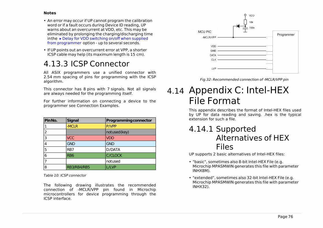
Page 76
Notes
• An error may occur if UP cannot program the calibrationword or if a fault occurs during Device ID reading, UPwarns about an overcurrent at VDD, etc. This may beeliminated by prolonging the charging/discharging timein the ▸ Delay for VDD switching on/off when suppliedfrom programmer option - up to several seconds.
• If UP points out an overcurrent error at VPP, a shorterICSP cable may help (its maximum length is 15 cm).
4.13.3 ICSP ConnectorAll ASIX programmers use a unified connector with2.54 mm spacing of pins for programming with the ICSPalgorithm.
This connector has 8 pins with 7 signals. Not all signalsare always needed for the programming itself.
For further information on connecting a device to theprogrammer see Connection Examples.
Pin No. Signal Programming connector
1 -MCLR P / VPP
2 not used (key)
3 VCC VDD
4 GND GND
5 RB7 D / DATA
6 RB6 C / CLOCK
7 not used
8 RB3/RB4/RB5 L / LVP
Table 10: ICSP connector
The following drawing illustrates the recommendedconnection of -MCLR/VPP pin found in Microchipmicrocontrollers for device programming through theICSP interface.
Fig.32: Recommended connection of -MCLR/VPP pin
4.14 Appendix C: Intel‑HEXFile FormatThis appendix describes the format of Intel-HEX files usedby UP for data reading and saving. .hex is the typicalextension for such a file.
4.14.1 SupportedAlternatives of HEXFiles
UP supports 2 basic alternatives of Intel-HEX files:
• "basic", sometimes also 8-bit Intel-HEX File (e.g.Microchip MPASMWIN generates this file with parameterINHX8M).
• "extended", sometimes also 32-bit Intel-HEX File (e.g.Microchip MPASMWIN generates this file with parameterINHX32).
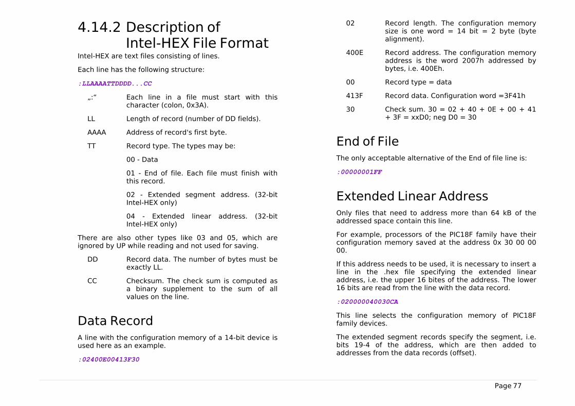
Page 77
4.14.2 Description ofIntel‑HEX File Format
Intel-HEX are text files consisting of lines.
Each line has the following structure:
:LLAAAATTDDDD...CC
„:“ Each line in a file must start with thischaracter (colon, 0x3A).
LL Length of record (number of DD fields).
AAAA Address of record's first byte.
TT Record type. The types may be:
00 - Data
01 - End of file. Each file must finish withthis record.
02 - Extended segment address. (32-bitIntel-HEX only)
04 - Extended linear address. (32-bitIntel-HEX only)
There are also other types like 03 and 05, which areignored by UP while reading and not used for saving.
DD Record data. The number of bytes must beexactly LL.
CC Checksum. The check sum is computed asa binary supplement to the sum of allvalues on the line.
Data RecordA line with the configuration memory of a 14-bit device isused here as an example.
:02400E00413F30
02 Record length. The configuration memorysize is one word = 14 bit = 2 byte (bytealignment).
400E Record address. The configuration memoryaddress is the word 2007h addressed bybytes, i.e. 400Eh.
00 Record type = data
413F Record data. Configuration word =3F41h
30 Check sum. 30 = 02 + 40 + 0E + 00 + 41+ 3F = xxD0; neg D0 = 30
End of FileThe only acceptable alternative of the End of file line is:
:00000001FF
Extended Linear AddressOnly files that need to address more than 64 kB of theaddressed space contain this line.
For example, processors of the PIC18F family have theirconfiguration memory saved at the address 0x 30 00 0000.
If this address needs to be used, it is necessary to insert aline in the .hex file specifying the extended linearaddress, i.e. the upper 16 bites of the address. The lower16 bits are read from the line with the data record.
:020000040030CA
This line selects the configuration memory of PIC18Ffamily devices.
The extended segment records specify the segment, i.e.bits 19-4 of the address, which are then added toaddresses from the data records (offset).
Page 78
Saving Device Type in .hex FileUsers frequently mistook the selected device type for thedevice type for which the .hex file was saved. Toeliminate this, UP contains a function allowing you to savethe device type in a file.
The program adds one more line below the End of File:#PART=.... The absolute majority of programs workingwith Intel-HEX files ignore this line, but such a modifiedfile cannot be considered as complying with the Intel-HEXformat.
Page 79
5
PRESTO.DLL Library
The presto.dll library has been designed for workingtogether with the PRESTO programmer.
The implemented functions allow you to set logical levelsat different programmer's pins as needed or to read theirstate. Various communication protocols can be createdthanks to this.
The function QsetPins() is provided for controlling allpins that can work as an output, while the functionQGetPins() serves for reading pins working as an input.
The function QSendByte() allows you to quickly send anSPI Byte to data and clock pins. If reading is needed atthe same time, use the QsendByte_OutIn() function.
In addition there are functions for setting theprogrammer's characteristics, controlling the voltage orreading the return values.
This library can be used with all revisions of the PRESTOprogrammer regardless of the hardware version.
The functions implemented in the presto.dll library aredescribed in detail in a separate document devoted tothis library.

Page 80
6
JTAG PLAYER
JTAG PLAYER is a utility designed for programmingdevices with the JTAG interface by means of PRESTO orFORTE programmers.
This utility is not part of the UP software installation packbut it can be downloaded separately from http://www.asix.cz/dwnld_jtag-svf-player.htm
JTAG PLAYER is localized only in English.
6.1 JTAG DeviceProgrammingHaving started JTAG PLAYER, select your programmer inOptions ➙ Select Programmer.
If you cannot see your connected programmer in thedialog window, check if the green ON-LINE LED on theprogrammer is on. If so, make sure thatanother softwareis not communicating with the programmer.
Program the device by choosing File ➙ Open&Process.The file to be programmed must be in SVF/XSVF format.For more information on the file format see SVF File orXSVF File.
If an error occurs during the programming process, checkthe connection between the programmer and theapplication. In addition, check the presence of a feedingvoltage.
Important warning
A power supply voltage from an external source must bepresent during programming that utilizes the JTAGinterface. The programmer does not feed the applicationin this case.
6.1.1 SVF FileSVF (Serial Vector Format) is a file used for describinghigh-level operations on the IEEE 1149.1 bus.
Serial Vector Format (.svf) is the recommended fileformat for all the testing and programming exceptfor Xilinx CPLD XC9500. The Xilinx Serial VectorFormat (.xsvf) is recommended for Xilinx CPLD XC9500.
Examples of How to Create SVFFilesThis chapter presents methods of creating an SVF file fordifferent types of device.
Atmel AVR (e.g. ATmega128)Programming
Generate an SVF file using the avrsvf.exe programavailable at the ATMEL website in the “Tools & Softwareof AVR 8-bit RISC MCUs” section.
Example:
avrsvf -datmega128 -s -e -ifmyfile.hex -pf -vf -ovmyfile.svf -mp
This example shows how to create an SVF file from themyfile.hex file. The final SVF file is then used byjtagplay.exe for erasing, programming and verification.Run avrsvf -h for more information.
The device must be in the reset state duringprogramming.
Page 81
Notes
Some AVR devices do not support page by pageprogramming. In such a case, the SVF file must becreated without the -mp parameter.
Lattice CPLD Programming
SVF file can be created from a .JED file using ispVMSystem. This program is part of the ispLEVER Classicsystem, which is available at the Lattice website.
Altera CPLD Programming
The QUARTUS II program by Altera can generate SVF filesif it is set up so in the menu.
Such an SVF file, however, cannot be used as it is due toa wrong Silicon ID. According to Altera, SVF filesgenerated by their software are assumed only for ATE(Automatic Test Equipment) programmers and Alteradoes not consider supporting others.
However, such an SVF file can be manually modified tosuit our needs. In order to do so, delete the "CHECKINGSILICON ID" section in the SVF file or mark it as a non-executable comment.
State of .svf FileImplementationThe SVF file support has been implemented in accordancewith the "Serial Vector Format Specification, Revision E"available at www.asset-intertech.com/support/svf.htmlwith the following limitations:
• PIO a PIOMAP commands are not implemented.
• HDR+SDR+TDR / HIR+SIR+TIR length is limited to2^31 bits.
• Supported TCK frequencies are 3 MHz, 1.5 MHz,750 kHz and fragments of 1 MHz starting at 500 kHz forPRESTO. FORTE adds 15 MHz, 10 MHz and 5 MHz on topof these.
• RUNTEST MAXIMUM max_time SEC parameter isignored.
• UNTEST run_count is limited to 2^31/3 (approximately715 million).
• RUNTEST min_time SEC is limited to 2^31/3 ms(approximately 715 seconds).
• TRST and RUNTEST SCK – these commands share thesame configurable P/VPP pin of both the PRESTO andFORTE programmers and can never be used together.
6.1.2 XSVF FileXSVF (Xilinx Serial Vector Format) is a file used fordescribing high-level operations on the IEEE 1149.1 busextended by Xilinx.
XSVF is recommended for Xilinx CPLD XC9500.
Examples of How to CreateXSVF FilesXilinx CPLD Programming
To create an XSVF file, use the iMPACT program availableat the Xilinx website.
Choose Prepare Configuration Files ➙ Boundary-Scan File ➙ XSVF File in the Operation ModeSelection dialog window that opens after the iMPACTprogram starts. Run all operations (Erase, Program,Verify, Test...) the same way as if a programmer wasconnected (e.g. Xilinx Parallel Cable). Then save the newfile and close iMPACT. Running the created XSVF file willperform the recorded operations.
We do not recommend using an SVF file forprogramming devices of the Xilinx XC9500 family, as thealgorithm for XC9500/XL/XV device programming cannotbe correctly described in the SVF format.
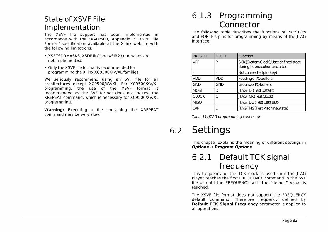
Page 82
State of XSVF FileImplementationThe XSVF file support has been implemented inaccordance with the "XAPP503, Appendix B: XSVF FileFormat" specification available at the Xilinx website withthe following limitations:
• XSETSDRMASKS, XSDRINC and XSIR2 commands arenot implemented.
• Only the XSVF file format is recommended forprogramming the Xilinx XC9500/XV/XL families.
We seriously recommend using an SVF file for allarchitectures except XC9500/XV/XL. For XC9500/XV/XLprogramming, the use of the XSVF format isrecommended as the SVF format does not include theXREPEAT command, which is necessary for XC9500/XV/XLprogramming.
Warning: Executing a file containing the XREPEATcommand may be very slow.
6.1.3 ProgrammingConnector
The following table describes the functions of PRESTO'sand FORTE's pins for programming by means of the JTAGinterface.
PRESTO FORTE Function
VPP P SCK (System Clock)/User defined stateduring file execution and after.
- - Not connected pin (key)
VDD VDD Feeding of I/O buffers
GND GND Ground of I/O buffers
MOSI D JTAG TDI (Test Data In)
CLOCK C JTAG TCK (Test Clock)
MISO I JTAG TDO (Test Data out)
LVP L JTAG TMS (Test Machine State)
Table 11: J TAG programming connector
6.2 SettingsThis chapter explains the meaning of different settings inOptions ➙ Program Options.
6.2.1 Default TCK signalfrequency
This frequency of the TCK clock is used until the JTAGPlayer reaches the first FREQUENCY command in the SVFfile or until the FREQUENCY with the "default" value isreached.
The XSVF file format does not support the FREQUENCYdefault command. Therefore frequency defined byDefault TCK Signal Frequency parameter is applied toall operations.
Page 83
The maximum frequency is 3 MHz for the PRESTOprogrammer and 15 MHz for FORTE.
If the Ignore FREQUENCY commands option is selected,the programmer applies only the frequency set by theuser and ignores all FREQUENCY commands.
6.2.2 Fast Clocks Option(FORTE only)
This option is available only for the FORTE programmer.
According to the JTAG specification, the signal at TDI issampled at TCK's rising edge. However, should a higherfrequency be required (around 5 MHz or more), it may beuseful to change the moment of sampling from the risingedge to the falling edge by shifting it by 1/2 of the TCKperiod. To do so, choose Fast Clock Option.
6.2.3 RUNTEST withoutrun_count (SVF only)
The programmer should stay in the specified state for thespecified time and generate the clock signal on TCK whileexecuting an SVF file.
The specified time can be exceeded, but it slows theprogramming process down. Even though it is notsupported by the SVF specification, many programmabledevices allow stopping the TCK clock during this time.
The programmer's ability to keep accurate time needs tobe considered. A high level of accuracy cannot beachieved if the maximum frequency is used (theprogrammer can guarantee respecting the min_time SECparameter only). A higher accuracy can be achieved withslow clock (~100 kHz). If the clock signal is not used atall, the programmer is capable of following the min_timeSEC parameter almost exactly.
Three possibilities are available considering these facts:
• no clock on TCK
• slow clock on TCK (~100 kHz)
• default speed clock on TCK
Example: "RUNTEST 3E-3 SEC;" means "Generate clock onTCK for at least 3 ms".
6.2.4 RUNTEST TimingMultiply (both SVFand XSVF)
Recommended values:
• for accurate timing specified in the SVF or XSVF file: 0%(no added time)
• for XC9500(XL) family: 100% or more
• for Atmel AVR (e.g. ATmega128): 25%
6.2.5 RUNTEST withrun_count and notiming(both SVF and XSVF)
This command should be interpreted as the minimumfrequency on TCK.
Yet some SVF file generators (such as Xilinx iMPACT, forexample) use this command as waiting time and assumea frequency of 1 MHz. For such cases the use of "interpretas RUNTEST min_time with scale 1 MHz" setting isrecommended.
JTAG Player Behavior When Reaching RUNTIMECommand With MINTIME Specification
(This concerns only SVF files as the RUNTEST alternative,which is usable in XSVF XRUNTEST run_count cannotspecify time.)
Page 84
• The RUNTEST command containing run_count andspecifying min_time is executed at the currentlyrunning TCK frequency. Therefore the command cantake much more time than what is specified inmin_time.
• The RUNTEST command containing run_count andspecifying max_time is executed at the currentlyrunning TCK frequency. As the programmer cannotrespect the “deadline” specified in the max_timeparameter, this parameter is ignored.
6.2.6 VPP PRESTO / PFORTE pin usagewhile running test(file) / after testcompletion
The selection of the VPP / P pin function: TRST or SCK asdescribed in the SVF file or user-defined output levels.(This is useful to keep the device in the reset state duringfile execution.)
6.2.7 Default SettingsThe JTAG Player features several default settings intendedprimarily for use in connection with FORTE, but not withPRESTO. Feel free to change these settings if the defaultvalues do not suit your application.
Default Settings for FPGAsDefault TCK frequency: 15 MHz; Ignore FREQUENCYcommands
Fast Clock Option (FORTE only): 5 MHz and above
RUNTEST without run_count (SVF only): defaultspeed clock on TCK
RUNTEST timing multiply (both SVF and XSVF): 0%
RUNTEST with run_count and no timing (both SVFand XSVF): interpret as RUNTEST min_time with scale1 MHz
VPP PRESTO / P FORTE pin usage while running test(file): Tristate
VPP PRESTO / P FORTE pin usage after testcompletion: Tristate
Default Settings for XC9500Default TCK frequency: 5 MHz; Ignore FREQUENCYcommands
Fast Clock Option (FORTE only): 5 MHz and above
RUNTEST without run_count (SVF only): slow clockon TCK (~100 kHz)
RUNTEST timing multiply (both SVF and XSVF):100%
RUNTEST with run_count and no timing (both SVFand XSVF): interpret as RUNTEST min_time with scale1 MHz
VPP PRESTO / P FORTE pin usage while running test(file): Tristate
VPP PRESTO / P FORTE pin usage after testcompletion: Tristate
Default Settings for AVR:Default TCK frequency: 1 MHz; Ignore FREQUENCYcommands
Fast Clock Option (FORTE only): 5 MHz and above
RUNTEST without run_count (SVF only): defaultspeed clock on TCK

Page 85
RUNTEST timing multiply (both SVF and XSVF):25%
RUNTEST with run_count and no timing (both SVFand XSVF): interpret as RUNTEST min_time with scale1 MHz
VPP PRESTO / P FORTE pin usage while running test(file): Tristate
VPP PRESTO / P FORTE pin usage after testcompletion: Tristate
6.3 Running JTAG Playerfrom Command LineSVF & XSVF JTAG Player can be run from the commandline for more comfort especially during debugging. Thefollowing parameters apply:
jtagplay.exe [-p] [-f filename] [-i inifile] [-c] [-cc] [-s serial]
-p automatically executes the file specified inthe -f filename parameter
-f filename specifies SVF / XSVF file to be executed
-i inifile ini file containing settings
-c closes the program if the file has beenexecuted without errors
-cc closes the program even if the file has beenexecuted with error(s)
-s serial uses PRESTO or FORTE programmer of thespecified serial number
-forte uses FORTE, not PRESTO
Return Codes
The jtagplay.exe program returns the following returncodes:
0 execution of the last file had no errors
1 an error occurred during execution of thelast file
2 execution of the last file could not bestarted

Page 86
7
TROUBLE-SHOOTING
This chapter describes how to proceed if experiencingdifficulties with device programming. It also describestesting utilities for PRESTO and FORTE programmersdesigned to check if the programmer is in good conditionor damaged. Please go through all the tips and tricksbefore you send your programmer to a service shop.
The testing utilities are not part of the UP softwareinstallation, but they can be downloaded separately fromhttp://tools.asix.net/supp_testers.htm.
7.1 Tips and TricksShould you experience difficulties with programming, werecommend checking the following points:
• Check the microcontroller and programmer connectionsaccording to the description in Connecting toApplication. Even though it may seem trivial, it isrecommended to check the connection twice and toassume the second time that the link does not alwayslead where you want it to or it leads to more than onepoint.
• If a crystal or other auxiliary devices are used forprogramming, (typically pull-down or pull-up resistors),check if their values and connections are correct.
• It is advisable (and often necessary) to have blockingcapacitors at the power supply of the device to beprogrammed.
• If the device to be programmed has more than onepower-supplying pin, all of them must be really fed. It isoften recommended to check their voltage with avoltmeter.
• Use of the latest version of UP is recommended. If youare still using an older version, an update isrecommended.
• Are you programming a new device or has it beenpreviously programmed? If so, the problems may becaused by unsuitably set fuses in the device.
• The length of the ICSP cable should not exceed 15 cm.
• Make sure that there is no additional capacity presentat the programming (data) pins. Consider if circuits onthe programming pins could cause too large a load forprogramming.
• It is important that the crystal or the communicationspeed settings reflect the reality in devices that needthat settings.
• Some devices may be programmed using severaldifferent methods. Programming problems may becaused by selecting a different programming interfaceor a different programming mode than the ones thatthe application is prepared for.
If none of the above tips help to eliminate the problemand if it absolutely sure that the device to beprogrammed is not faulty, the fault may lie in theprogrammer.
To easily find out whether the programmer is in order ornot, you can use the testing utilities described in thefollowing chapters.
7.2 PRESTO Testerhe PRESTO Tester utility easily tests the “healthstate” (usability) of the PRESTO programmer right at thecustomer's site.
In order to run it successfully, only one PRESTOprogrammer may be connected to the control PC and itsdrivers must be correctly installed. This is confirmed bythe green LED being on.
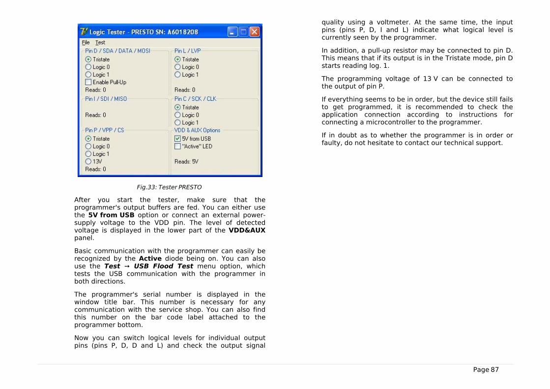
Page 87
Fig.33: Tester PRESTO
After you start the tester, make sure that theprogrammer's output buffers are fed. You can either usethe 5V from USB option or connect an external power-supply voltage to the VDD pin. The level of detectedvoltage is displayed in the lower part of the VDD&AUXpanel.
Basic communication with the programmer can easily berecognized by the Active diode being on. You can alsouse the Test ➙ USB Flood Test menu option, whichtests the USB communication with the programmer inboth directions.
The programmer's serial number is displayed in thewindow title bar. This number is necessary for anycommunication with the service shop. You can also findthis number on the bar code label attached to theprogrammer bottom.
Now you can switch logical levels for individual outputpins (pins P, D, D and L) and check the output signal
quality using a voltmeter. At the same time, the inputpins (pins P, D, I and L) indicate what logical level iscurrently seen by the programmer.
In addition, a pull-up resistor may be connected to pin D.This means that if its output is in the Tristate mode, pin Dstarts reading log. 1.
The programming voltage of 13 V can be connected tothe output of pin P.
If everything seems to be in order, but the device still failsto get programmed, it is recommended to check theapplication connection according to instructions forconnecting a microcontroller to the programmer.
If in doubt as to whether the programmer is in order orfaulty, do not hesitate to contact our technical support.
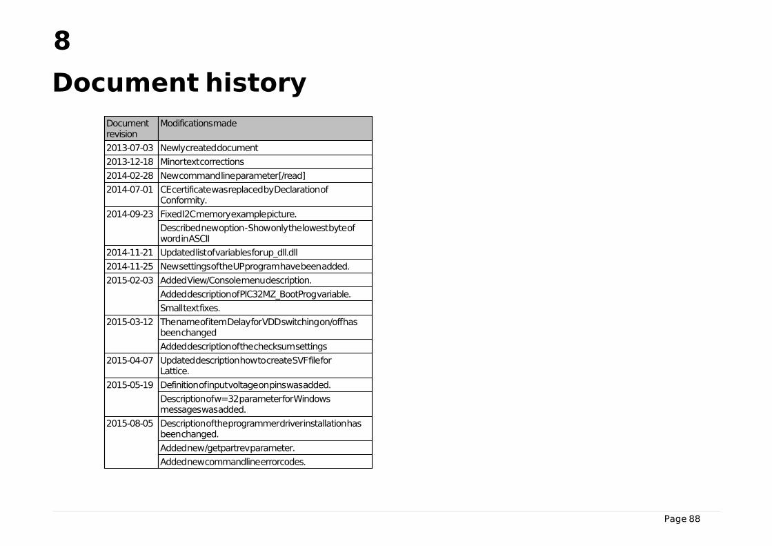
Page 88
8
Document history
Documentrevision
Modifications made
2013-07-03 Newly created document
2013-12-18 Minor text corrections
2014-02-28 New command line parameter [/read]
2014-07-01 CE certificate was replaced by Declaration ofConformity.
2014-09-23 Fixed I2C memory example picture.
Described new option - Show only the lowest byte ofword in ASCII
2014-11-21 Updated list of variables for up_dll.dll
2014-11-25 New settings of the UP program have been added.
2015-02-03 Added View/Console menu description.
Added description of PIC32MZ_BootProg variable.
Small text fixes.
2015-03-12 The name of item Delay for VDD switching on/off hasbeen changed
Added description of the checksum settings
2015-04-07 Updated description how to create SVF file forLattice.
2015-05-19 Definition of input voltage on pins was added.
Description of w=32 parameter for Windowsmessages was added.
2015-08-05 Description of the programmer driver installation hasbeen changed.
Added new /getpartrev parameter.
Added new commandline errorcodes.


![Amarasimha_ Namalinganusasana [Amarakosa], Kanda 2](https://img.pdfslide.us/doc/110x75/552dfc2a4a795978658b47f6/amarasimha-namalinganusasana-amarakosa-kanda-2.jpg)


![Amarasimha_ Namalinganusasana [Amarakosa], Kanda 1](https://img.pdfslide.us/doc/110x75/552dfbf8550346231a8b4843/amarasimha-namalinganusasana-amarakosa-kanda-1.jpg)