Embed Size (px)
Citation preview
LR72Z-0˙˙-˙˙N
EN 61373
0
1
2
3
4
5
6
7
8
9
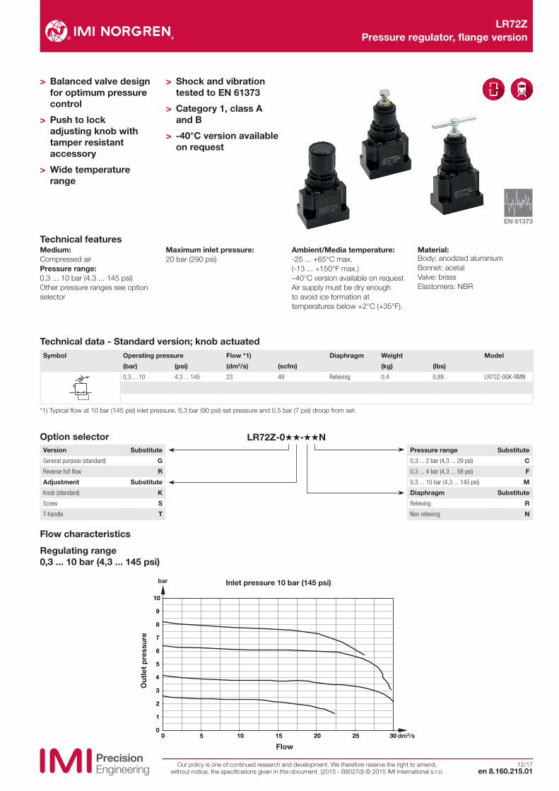
10
0 5 10 15 20 25 30 dm3/s
bar
LR72Z Pressure regulator, flange version
12/17en 8.160.215.01
Our policy is one of continued research and development. We therefore reserve the right to amend, without notice, the specifications given in this document. (2015 - B8027d) © 2015 IMI International s.r.o.
Technical features
> Balanced valve design for optimum pressure control
> Push to lock adjusting knob with tamper resistant accessory
> Wide temperature range
> Shock and vibration tested to EN 61373
> Category 1, class A and B
> -40°C version available on request
Version Substitute
General purpose (standard) G
Reverse full flow R
Adjustment Substitute
Knob (standard) K
Screw S
T-handle T
Pressure range Substitute
0,3 ... 2 bar (4,3 ... 29 psi) C
0,3 ... 4 bar (4,3 ... 58 psi) F
0,3 ... 10 bar (4,3 ... 145 psi) M
Diaphragm Substitute
Relieving R
Non relieving N
Medium:Compressed airPressure range:0,3 ... 10 bar (4.3 ... 145 psi)Other pressure ranges see option selector
Maximum inlet pressure: 20 bar (290 psi)
Ambient/Media temperature:-25 ... +65°C max.(-13 ... +150°F max.) –40°C version available on requestAir supply must be dry enough to avoid ice formation at temperatures below +2°C (+35°F).
Material:Body: anodized aluminiumBonnet: acetalValve: brassElastomers: NBR
Option selector
Technical data - Standard version; knob actuatedSymbol Operating pressure Flow *1) Diaphragm Weight Model
(bar) (psi) (dm3/s) (scfm) (kg) (lbs)
0,3 ... 10 4.3 ... 145 23 49 Relieving 0,4 0,88 LR72Z-0GK-RMN
*1) Typical flow at 10 bar (145 psi) inlet pressure, 6,3 bar (90 psi) set pressure and 0,5 bar (7 psi) droop from set.
Flow characteristics
Regulating range 0,3 ... 10 bar (4,3 ... 145 psi)
Flow
Inlet pressure 10 bar (145 psi)
Out
let
pre
ssur
e
4
15
4522 11
7
21
ø 29
13
32
50
62
ø 5,5
ø 2
4230
15
214
,5
3
5
5
4
15
4522
2
110
21 3
ø 35
32
50
62
ø 5,5
ø 2
14,5
4230
15
5
5
45
5
15
4522 12
5
21
64
32
50
62
ø 5,5
ø 24230
15
214
,5
3
LR72Z Pressure regulator, flange version
Our policy is one of continued research and development. We therefore reserve the right to amend, without notice, the specifications given in this document. (2015 - B8027d) © 2015 IMI International s.r.o.en 8.160.215.02
12/17
Warning
These products are intended for use in industrial compressed air and rail transport systems only. Do not use these products where pressures and temperatures can exceed those listed under »Technical features/data«. Before using these products with fluids other than those specified, for non-industrial applications, life-support systems or other applications not within published specifications, consult IMI Precision Engineering, IMI International s.r.o.
Through misuse, age, or malfunction, components used in fluid power systems can fail in various modes. The system designer is warned to consider the failure modes of all component parts used in fluid power systems and to provide adequate safeguards to prevent personal injury or damage to equipment in the event of such failure. System designers must provide a warning to end users in the system instructional manual if protection against a failure mode cannot be adequately provided. System designers and end users are cautioned to review specific warnings found in instruction sheets packed and shipped with these products.
EN - Englisch
AccessoriesTamper resistant cover & seal wire
Service kit
4255-51 A1333-S01 (relieving)
A1333-S02 (non-relieving)
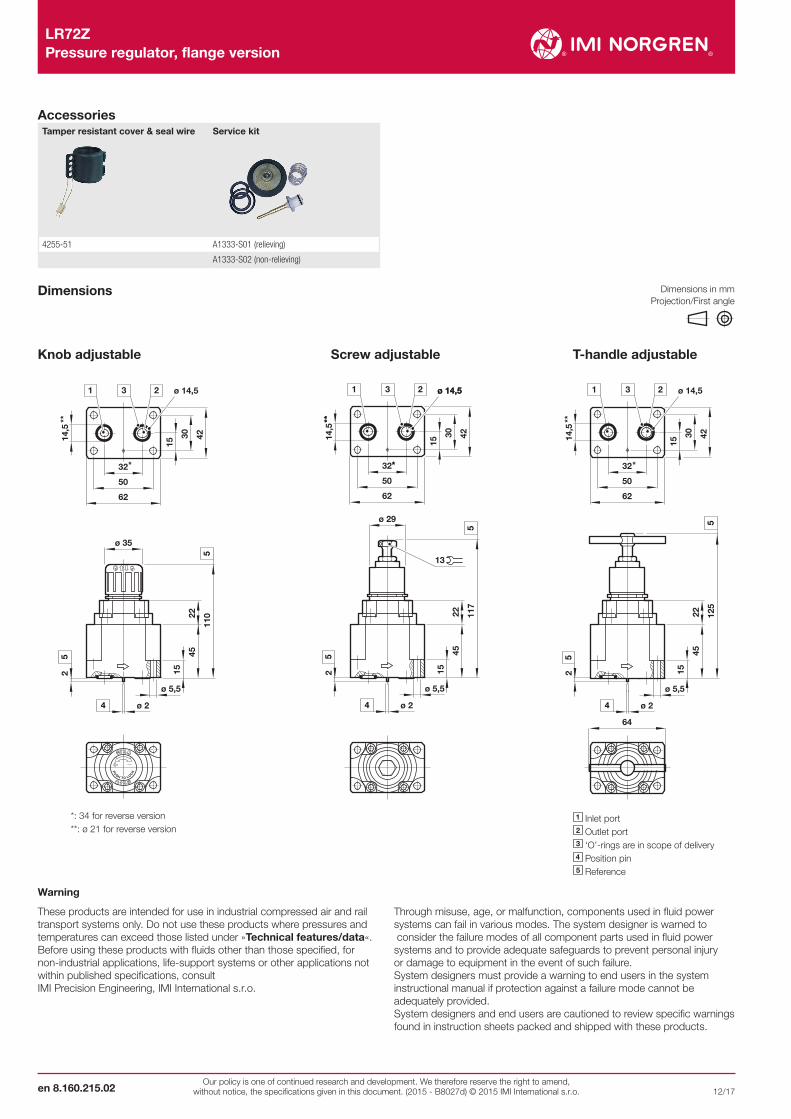
Dimensions
Knob adjustable Screw adjustable T-handle adjustable
1 Inlet port 2 Outlet port 3 ‘O’-rings are in scope of delivery 4 Position pin5 Reference
ø 14,5
*
**
*: 34 for reverse version**: ø 21 for reverse version
ø 14,5
*
**
ø 14,5
*
**
ø 14,5
*
**
Dimensions in mm Projection/First angle