Embed Size (px)
Citation preview
VALVES
2
VAL-311For further information www.norgren.com
Standard Manifold
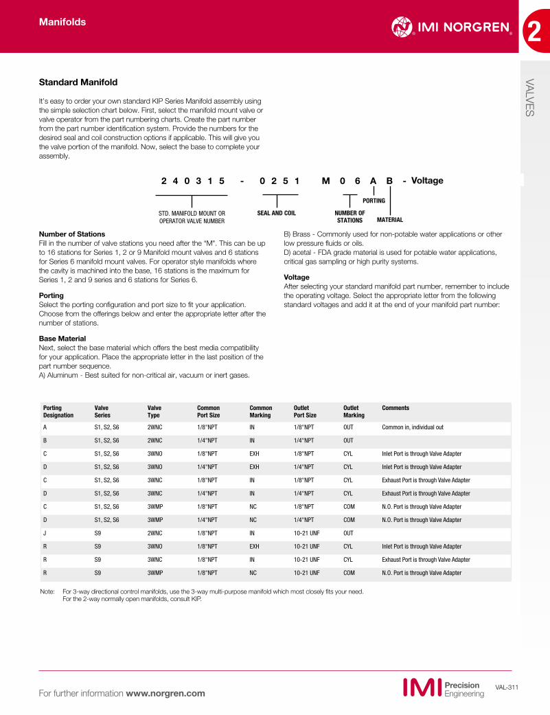
It’s easy to order your own standard KIP Series Manifold assembly using the simple selection chart below. First, select the manifold mount valve or valve operator from the part numbering charts. Create the part number from the part number identification system. Provide the numbers for the desired seal and coil construction options if applicable. This will give you the valve portion of the manifold. Now, select the base to complete your assembly.
Number of StationsFill in the number of valve stations you need after the “M". This can be up to 16 stations for Series 1, 2 or 9 Manifold mount valves and 6 stations for Series 6 manifold mount valves. For operator style manifolds where the cavity is machined into the base, 16 stations is the maximum for Series 1, 2 and 9 series and 6 stations for Series 6.
PortingSelect the porting configuration and port size to fit your application. Choose from the offerings below and enter the appropriate letter after the number of stations.
Base Material Next, select the base material which offers the best media compatibility for your application. Place the appropriate letter in the last position of the part number sequence.A) Aluminum - Best suited for non-critical air, vacuum or inert gases.
B) Brass - Commonly used for non-potable water applications or other low pressure fluids or oils.D) acetal - FDA grade material is used for potable water applications, critical gas sampling or high purity systems.
VoltageAfter selecting your standard manifold part number, remember to include the operating voltage. Select the appropriate letter from the following standard voltages and add it at the end of your manifold part number:
STD. MANIFOLD MOUNT OR OPERATOR VALVE NUMBER
SEAL AND COIL NUMBER OF STATIONS
PORTING
MATERIAL
2 4 0 3 1 5 - 0 2 5 1 M 0 6 A B -
Note: For 3-way directional control manifolds, use the 3-way multi-purpose manifold which most closely fits your need. For the 2-way normally open manifolds, consult KIP.
Porting Designation
Valve Series
Valve Type
Common Port Size
Common Marking
Outlet Port Size
Outlet Marking
Comments
A S1, S2, S6 2WNC 1/8"NPT IN 1/8"NPT OUT Common in, individual out
B S1, S2, S6 2WNC 1/4"NPT IN 1/4"NPT OUT
C S1, S2, S6 3WNO 1/8"NPT EXH 1/8"NPT CYL Inlet Port is through Valve Adapter
D S1, S2, S6 3WNO 1/4"NPT EXH 1/4"NPT CYL Inlet Port is through Valve Adapter
C S1, S2, S6 3WNC 1/8"NPT IN 1/8"NPT CYL Exhaust Port is through Valve Adapter
D S1, S2, S6 3WNC 1/4"NPT IN 1/4"NPT CYL Exhaust Port is through Valve Adapter
C S1, S2, S6 3WMP 1/8"NPT NC 1/8"NPT COM N.O. Port is through Valve Adapter
D S1, S2, S6 3WMP 1/4"NPT NC 1/4"NPT COM N.O. Port is through Valve Adapter
J S9 2WNC 1/8"NPT IN 10-21 UNF OUT
R S9 3WNO 1/8"NPT EXH 10-21 UNF CYL Inlet Port is through Valve Adapter
R S9 3WNC 1/8"NPT IN 10-21 UNF CYL Exhaust Port is through Valve Adapter
R S9 3WMP 1/8"NPT NC 10-21 UNF COM N.O. Port is through Valve Adapter
Voltage
Manifolds
2
VALVES
VAL-312For further information www.norgren.com
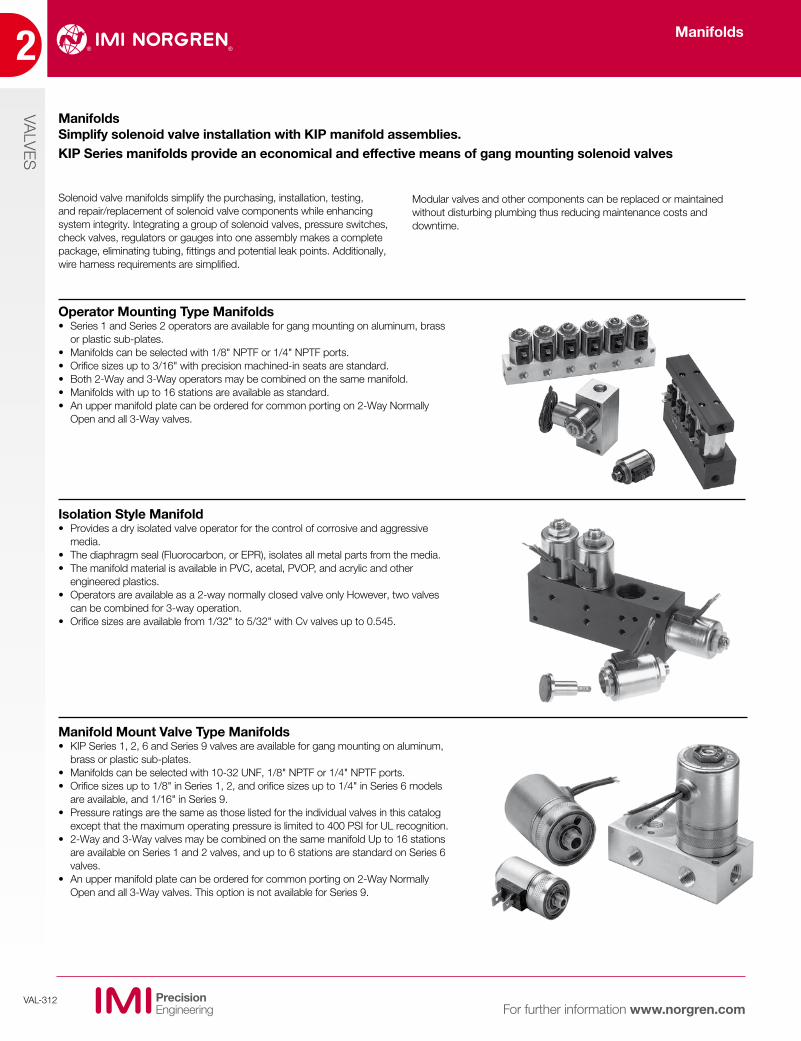
Operator Mounting Type Manifolds• Series 1 and Series 2 operators are available for gang mounting on aluminum, brass
or plastic sub-plates.• Manifolds can be selected with 1/8" NPTF or 1/4" NPTF ports.• Orifice sizes up to 3/16" with precision machined-in seats are standard.• Both 2-Way and 3-Way operators may be combined on the same manifold.• Manifolds with up to 16 stations are available as standard.• An upper manifold plate can be ordered for common porting on 2-Way Normally
Open and all 3-Way valves.
Isolation Style Manifold• Provides a dry isolated valve operator for the control of corrosive and aggressive
media.• The diaphragm seal (Fluorocarbon, or EPR), isolates all metal parts from the media.• The manifold material is available in PVC, acetal, PVOP, and acrylic and other
engineered plastics.• Operators are available as a 2-way normally closed valve only However, two valves
can be combined for 3-way operation.• Orifice sizes are available from 1/32" to 5/32" with Cv valves up to 0.545.
Manifold Mount Valve Type Manifolds• KIP Series 1, 2, 6 and Series 9 valves are available for gang mounting on aluminum,
brass or plastic sub-plates.• Manifolds can be selected with 10-32 UNF, 1/8" NPTF or 1/4" NPTF ports.• Orifice sizes up to 1/8" in Series 1, 2, and orifice sizes up to 1/4" in Series 6 models
are available, and 1/16" in Series 9.• Pressure ratings are the same as those listed for the individual valves in this catalog
except that the maximum operating pressure is limited to 400 PSI for UL recognition.• 2-Way and 3-Way valves may be combined on the same manifold Up to 16 stations
are available on Series 1 and 2 valves, and up to 6 stations are standard on Series 6 valves.
• An upper manifold plate can be ordered for common porting on 2-Way Normally Open and all 3-Way valves. This option is not available for Series 9.
Solenoid valve manifolds simplify the purchasing, installation, testing, and repair/replacement of solenoid valve components while enhancing system integrity. Integrating a group of solenoid valves, pressure switches, check valves, regulators or gauges into one assembly makes a complete package, eliminating tubing, fittings and potential leak points. Additionally, wire harness requirements are simplified.
ManifoldsSimplify solenoid valve installation with KIP manifold assemblies. KIP Series manifolds provide an economical and effective means of gang mounting solenoid valves
Modular valves and other components can be replaced or maintained without disturbing plumbing thus reducing maintenance costs and downtime.
Manifolds
VALVES
2
VAL-313For further information www.norgren.com
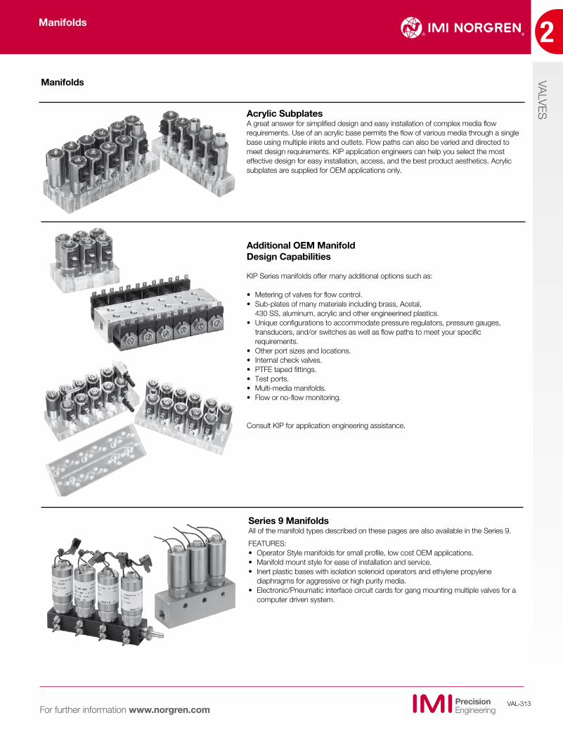
Acrylic SubplatesA great answer for simplified design and easy installation of complex media flow requirements. Use of an acrylic base permits the flow of various media through a single base using multiple inlets and outlets. Flow paths can also be varied and directed to meet design requirements. KIP application engineers can help you select the most effective design for easy installation, access, and the best product aesthetics. Acrylic subplates are supplied for OEM applications only.
Additional OEM Manifold Design Capabilities
KIP Series manifolds offer many additional options such as:
• Metering of valves for flow control.• Sub-plates of many materials including brass, Acetal, 430 SS, aluminum, acrylic and other engineerined plastics.• Unique configurations to accommodate pressure regulators, pressure gauges,
transducers, and/or switches as well as flow paths to meet your specific requirements.
• Other port sizes and locations.• Internal check valves.• PTFE taped fittings.• Test ports.• Multi-media manifolds.• Flow or no-flow monitoring.
Consult KIP for application engineering assistance.
Series 9 ManifoldsAll of the manifold types described on these pages are also available in the Series 9.
FEATURES:• Operator Style manifolds for small profile, low cost OEM applications.• Manifold mount style for ease of installation and service.• Inert plastic bases with isolation solenoid operators and ethylene propylene
diaphragms for aggressive or high purity media.• Electronic/Pneumatic interface circuit cards for gang mounting multiple valves for a
computer driven system.
Manifolds
Manifolds
2
VALVES
VAL-314For further information www.norgren.com
Vacuum Service KIP Series valves and manifolds are ideal for vacuum service and for those special 3-way valve applications that require vacuum on one port and pressure on another port. Valve construction is compatible with vacuum systems as high as 10-6 TORR.
Surface Treatment Services IMI Norgren offers several different surface treatment services that assist in cleaning and or protecting the valve and manifold surfaces. These treatments are:• Citric passivation process which assists in reducing the corrosion on stainless steel.• Nitric passivation process also assists to keep stainless steels from corroding, but is considered more invasive than the citric passivation process.• Electro-polishing process which removes a top layer of metal material of approximately .0005” - .0007”. • Anodizing process puts a proactive coating (approximately .0003” to .0005”) of oxidation in the exterior to protect against further oxidation. The covalent bonding of the exterior adds a surface that is much harder than the base material.• Hard-coat anodizing process puts a proactive coating (approximately .0008” to .0010”) of oxidation on the exterior from some wear and abrasion. • Oxygen cleaning process is used to further clean wetted valve com-ponents for gaseous or liquid oxygen systems. The oxygen cleaning process removes all residual contaminates, hydrocarbons, and other cleaning agents. After parts are oxygen cleaned, precautions should be taken to endure the parts remain clean.
Extended Flow Capabilities IMI Norgren can increase the flow (Cv) capability of any of its valves by modifying the mechanical and electrical components of the valve. In many cases the pressure ratings (MOPD) of the valve must be reduced to achieve the higher flow rate (Cv). When your flow requirements exceed the catalog ratings, consult IMI Norgren for application engineering assistance.
Extended Pressure Ratings Solenoid valves can be modified to increase pressure ratings (MOPD) above the standard ratings listed in the catalog. If agency approvals are necessary, consultation with UL and/or CSA is required. Consult IMI Norgren with all your design parameters to determine the feasibility of extending the pressure ratings.
Quiet Valves Solenoid valves have a distinct click that is inherent to their design when the two metal parts make contact. IMI Norgren offers a bumper or special plunger design for OEM’s that will provide a metal to elastomer contact, thus muffling the sound. In addition to providing quiet operation, this feature also extends the life of the moving parts. Quiet valves are available on 2-way and 3-way valves, DC voltage only. Contact IMI Norgren for additional information on our quiet valve option.
Agency Approvals IMI Norgren products conform to agency approvals such as UL, cURus, CSA and NSF International. All standard products are RoHS compliant. The approvals are restricted to certain products and specific applications. When any agency endorsement is dictated for an operation, refer to the application inquiry sheets for each product specified. The sheets are located in the back of the catalog. If additional information is needed, please contact IMI Norgren.
Low Wattage Operators, Valves and ManifoldsIMI Norgren offers the option of low wattage coils, as low as 1.5 watts, on many of our standard valves. These coils offer high pressure (MOPD) operation at low current levels.
• Available in both 2-Way and 3-Way models in Series 1, Series 2, and Series 3.
• Orifice sizes from 1/32" to 5/32".
• Available in 12 VDC and 24 VDC.
• Refer to IMI Norgren solenoid valve charts for wattage, pressure ratings and Cv factors.
KIP Series 1, 2 and 3 offer selective models with wattage ratings from 1.5 watts to 3 watts. After reviewing the pressure rating (MOPD) of your particular valve in the part number section, you may add an (A) - 1.5 watts, (B) - 2.0 watts, (C) - 2.5 watts, or a (D) - 3.0 watts as a prefix to the part number. It is important to note that there is a reduced pressure rating from the standard when a reduced wattage coil is used.
For the OEM, IMI Norgren can design and manufacture a custom coil to meet your specific flow and pressure requirements at close to standard pricing.
When 1.5 watts is not low enough, you can select a valve from the Series 9 product line which goes as low as .65 watts while still maintaining significant flow and pressure specifications.
Custom Capabilities
Manifolds
VALVES
2
VAL-315For further information www.norgren.com
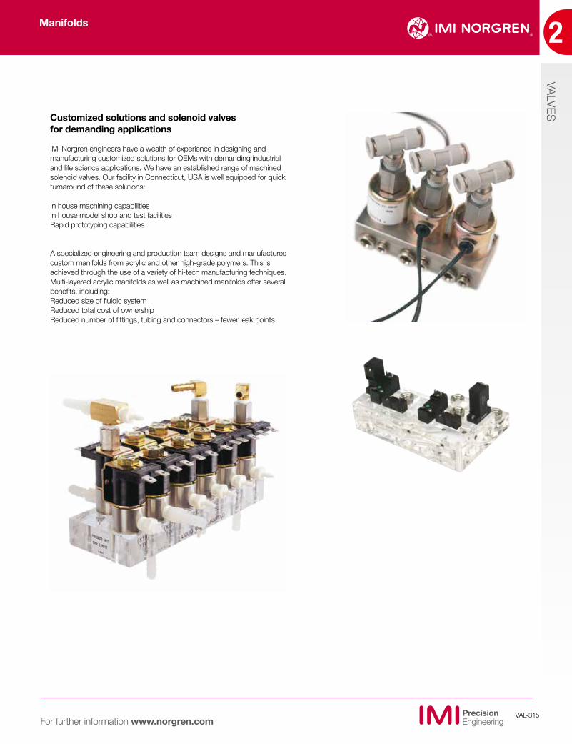
Customized solutions and solenoid valves for demanding applications
IMI Norgren engineers have a wealth of experience in designing and manufacturing customized solutions for OEMs with demanding industrial and life science applications. We have an established range of machined solenoid valves. Our facility in Connecticut, USA is well equipped for quick turnaround of these solutions:
In house machining capabilitiesIn house model shop and test facilitiesRapid prototyping capabilities
A specialized engineering and production team designs and manufactures custom manifolds from acrylic and other high-grade polymers. This is achieved through the use of a variety of hi-tech manufacturing techniques. Multi-layered acrylic manifolds as well as machined manifolds offer several benefits, including:Reduced size of fluidic systemReduced total cost of ownership Reduced number of fittings, tubing and connectors – fewer leak points
Manifolds

2
VALVES
VAL-316For further information www.norgren.com
Manifold Mount Base ValvesKIP Series standard manifold mount base valves offer a cost effective method of secu-ring valves to manifolds, eliminating custom cavities or seat installations. Testing is simpli-fied and manifold design and “O" Ring sealing provides quick installation, interchangea-bility, service and replacement, without removing a single supply line or fitting.
KIP Series manifold mount style valves are available in all Series from the Series 9 for low watt applications, to the Series 6 for high flow and high pressure requirements. Our complete line of manifold mount type valves allows you to mix and match different style valves on one manifold assembly to accommodate your application requirements.
Male Bottom PortThis option is available in Series 1, 2, & 3 with 1/8" NPT or 1/4" NPT male bottom port. The brass hex body has 1/8" NPT side ports for both the 1/8" and 1/4" models. Valves are available with a maximum orifice size of 1/8". When ordering a valve as a 2-way normally closed version, please indicate whether the male port is to be the inlet or outlet. The standard version has the side port as the inlet for both 2-way and 3-way valves.
This option is ideal as a 3-way operator for piloting a cylinder. Installation is fast and easy. Units also can be ordered with male thread PTFE tape to save you additional time. Available with any electrical termination or housing style.
Bottom Port- “O" Ring SealIMI Norgren offers an option on Series 1, 2, 3, and 6 for bottom ported valves with an “O" Ring seal. This option utilizes one or two ports on the bottom of the valve body to have a counterbore pocket for a face sealing “O" Ring. The manifold surface is simply machined flat with matching hole locations and through holes matching up with the mounting holes of the valves. When a valve is installed with the mounting screws the “O" Ring provides a seal between the bottom of the valve body and the manifold surface. This feature is ideal for acrylic or other plastic manifolds where there is concern for thread life or cracking of the block by over torquing.
Available in 2-way and 3-way valves. When only one bottom port is used, the remaining valve porting can be any of the options available in each series. Installation is quick and secure; trouble shooting or valve replacement can be accommodated with minimum effort.
Non standard item - consult factory.
Manifolds
VALVES
2
VAL-317For further information www.norgren.com
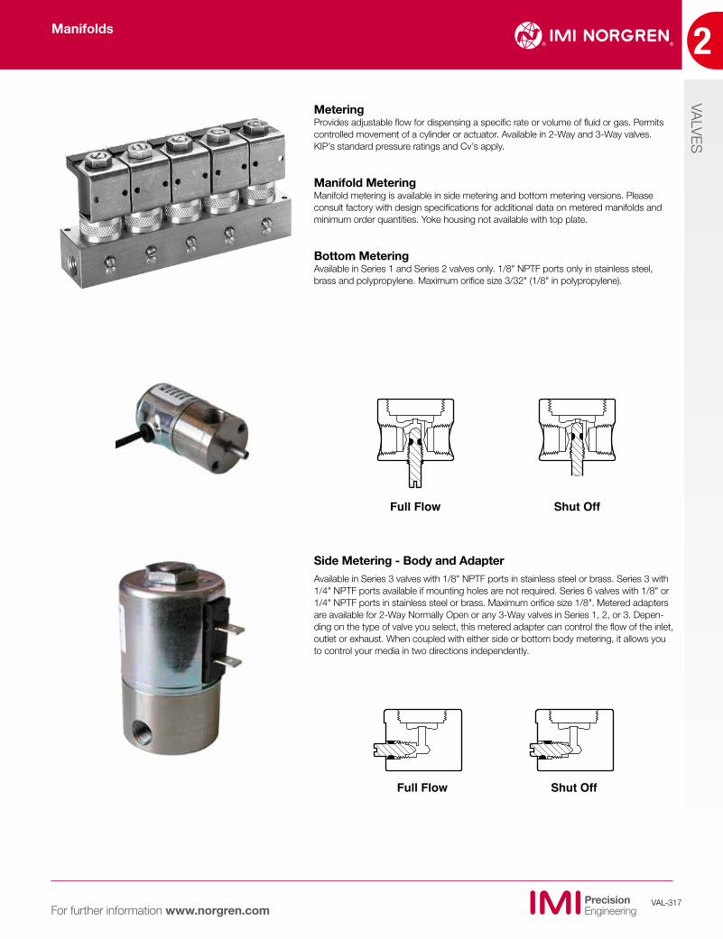
MeteringProvides adjustable flow for dispensing a specific rate or volume of fluid or gas. Permits controlled movement of a cylinder or actuator. Available in 2-Way and 3-Way valves. KIP’s standard pressure ratings and Cv’s apply.
Manifold Metering Manifold metering is available in side metering and bottom metering versions. Please consult factory with design specifications for additional data on metered manifolds and minimum order quantities. Yoke housing not available with top plate.
Bottom Metering Available in Series 1 and Series 2 valves only. 1/8" NPTF ports only in stainless steel, brass and polypropylene. Maximum orifice size 3/32" (1/8" in polypropylene).
Side Metering - Body and Adapter Available in Series 3 valves with 1/8" NPTF ports in stainless steel or brass. Series 3 with 1/4" NPTF ports available if mounting holes are not required. Series 6 valves with 1/8" or 1/4" NPTF ports in stainless steel or brass. Maximum orifice size 1/8". Metered adapters are available for 2-Way Normally Open or any 3-Way valves in Series 1, 2, or 3. Depen-ding on the type of valve you select, this metered adapter can control the flow of the inlet, outlet or exhaust. When coupled with either side or bottom body metering, it allows you to control your media in two directions independently.
Full Flow Shut Off
Full Flow Shut Off
Manifolds
2
VALVES
VAL-318For further information www.norgren.com
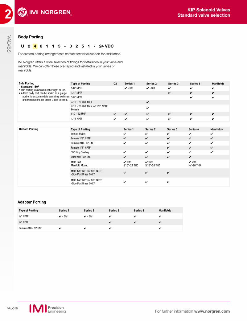
U 2 4 0 1 1 5 - 0 2 5 1 - 24 VDC
Body Porting
For custom porting arrangements contact technical support for assistance.
IMI Norgren offers a wide selection of fittings for installation in your valve and manifolds. We can offer these pre-taped and installed in your valves or manifolds.
KIP Solenoid ValvesStandard valve selection
Adapter Porting
Side Porting – Standard 180° • 90° porting is available either right or left. • A third body port can be added as a gauge
port or to accommodate sampling, switches and transducers, on Series 3 and Series 6.
Type of Porting Q2 Series 1 Series 2 Series 3 Series 6 Manifolds
1/8" NPTF 4 - Std 4 - Std 4 4 4
1/4" NPTF 4 4 4
3/8" NPTF 4 4
7/16 - 20 UNF Male 4
7/16 - 20 UNF Male w/ 1/8" NPTF Female 4
#10 - 32 UNF 4 4 4 4 4 4
1/16 NPTF 4 4 4 4 4 4
Bottom Porting Type of Porting Series 1 Series 2 Series 3 Series 6 Manifolds
Inlet or Outlet 4 4 4 4 4
Female 1/8" NPTF 4 4 4 4 4
Female #10 - 32 UNF 4 4 4 4 4
Female 1/4" NPTF 4 4 4
“O" Ring Sealing 4 4 4 4 4
Dual #10 - 32 UNF 4 4 4 4
Male Port Manifold Mount
4 with 5/16"-24 THD
4 with 5/16"-24 THD
4 with ½"-20 THD
Male 1/8" NPT w/ 1/8" NPTF -Side Port Brass ONLY 4 4 4
Male 1/4" NPT w/ 1/8" NPTF -Side Port Brass ONLY 4 4 4
Type of Porting Series 1 Series 2 Series 3 Series 6 Manifolds
1/8" NPTF 4 - Std 4 - Std 4 4 4
1/4" NPTF 4 4 4
Female #10 - 32 UNF 4 4 4 4
VALVES
2
VAL-319For further information www.norgren.com
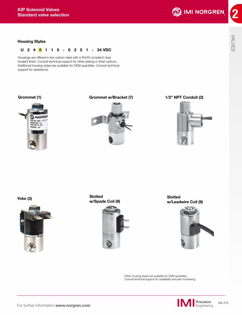
Grommet (1) Grommet w/Bracket (7) 1/2" NPT Conduit (2)
Yoke (3) Slotted w/Spade Coil (9)
Slotted w/Leadwire Coil (9)
Other housing styles are available for OEM quantities. Consult technical support for availability and part numbering.
U 2 4 0 1 1 5 - 0 2 5 1 - 24 VDC
Housing Styles
Housings are offered in low carbon steel with a RoHS compliant clear trivalent finish. Consult technical support for other plating or finish options. Additional housing styles are available for OEM quantities. Consult technical support for assistance.
KIP Solenoid ValvesStandard valve selection
2
VALVES
VAL-320For further information www.norgren.com
Body Material
We offer valve bodies in two standard materials. Brass and 303 Stainless Steel. Consult technical support for addtional body materials. See our valve custom capabilities section for additional options.
Valve Types
OUT
IN IN
De-energized EnergizedOUT
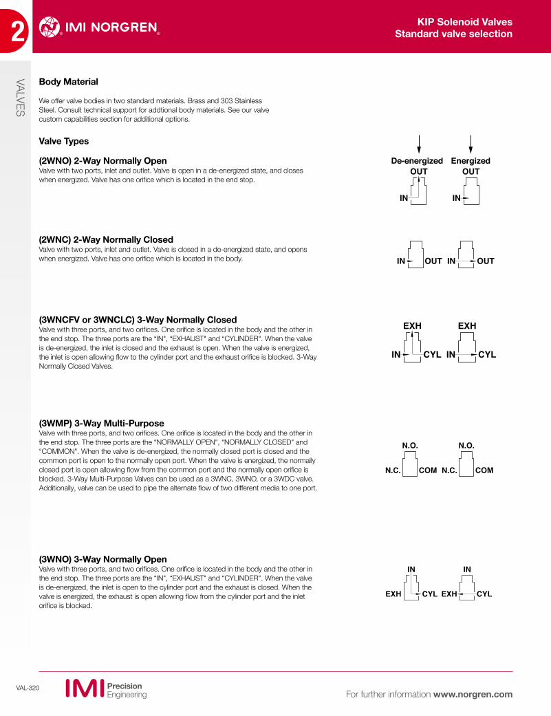
(2WNO) 2-Way Normally OpenValve with two ports, inlet and outlet. Valve is open in a de-energized state, and closes when energized. Valve has one orifice which is located in the end stop.
OUTINOUTIN
(2WNC) 2-Way Normally ClosedValve with two ports, inlet and outlet. Valve is closed in a de-energized state, and opens when energized. Valve has one orifice which is located in the body.
EXH
IN CYL
EXH
IN CYL
(3WNCFV or 3WNCLC) 3-Way Normally ClosedValve with three ports, and two orifices. One orifice is located in the body and the other in the end stop. The three ports are the “IN", “EXHAUST" and “CYLINDER". When the valve is de-energized, the inlet is closed and the exhaust is open. When the valve is energized, the inlet is open allowing flow to the cylinder port and the exhaust orifice is blocked. 3-Way Normally Closed Valves.
N.O.
N.C. COM
N.O.
N.C. COM
(3WMP) 3-Way Multi-PurposeValve with three ports, and two orifices. One orifice is located in the body and the other in the end stop. The three ports are the “NORMALLY OPEN", “NORMALLY CLOSED" and “COMMON". When the valve is de-energized, the normally closed port is closed and the common port is open to the normally open port. When the valve is energized, the normally closed port is open allowing flow from the common port and the normally open orifice is blocked. 3-Way Multi-Purpose Valves can be used as a 3WNC, 3WNO, or a 3WDC valve. Additionally, valve can be used to pipe the alternate flow of two different media to one port.
IN
EXH CYL
IN
EXH CYL
(3WNO) 3-Way Normally OpenValve with three ports, and two orifices. One orifice is located in the body and the other in the end stop. The three ports are the “IN", “EXHAUST" and “CYLINDER". When the valve is de-energized, the inlet is open to the cylinder port and the exhaust is closed. When the valve is energized, the exhaust is open allowing flow from the cylinder port and the inlet orifice is blocked.
KIP Solenoid ValvesStandard valve selection
VALVES
2
VAL-321For further information www.norgren.com
We offer standard-sized body orifices from 1/32" to 5/32" for KIP Series 1 through 6. Series 3 and 6 orifices are also available up to 1/4". We also offer a 3/8" body orifice in Series 6.
Standard end stop (top of valve) orifice sizes are available from 1/32" to 1/16" in Series 1.
Seals
Seal materials01 Buna - N A general purpose, soft, synthetic rubber suitable for most air, non-potable water and light oil environments with temperatures to 200° F.
02 Fluorocarbon A soft, fluorocarbon rubber used primarily with hydrocarbon liquids such as gasoline, aerospace fuels, solvents, etc., which can cause swelling and distortion to Buna. Fluorocarbon is also used for oxygen service. The material is appropriate for higher temperature ranges, and is more resistant to “dry" heat.
03 Standard Neoprene A sofe, synthetic rubber with excellent low temperature sealing and very good heat aging resistance.
05 Low Temperature Buna Primarily used in low temperature applications down to -40° F/C. Suitable for most air, non-potable water, and light oil environments.
06 Polyurethane Primarily used for high load applications involving non-corrosive gases & oils. Especially good for high pressure gases prone to absorption such as CO2. Not recommended for water, acids or chlorinated solvents.
Up to 5/64" in KIP Series 2 and 3 valves and up to 1/8" in Series 6 valves. In addition, we offer larger end stop orifices on all Series 1, 2 & 3 to maximize flow. However, these orifices are application-sensitive. Please consult technical support for assistance.
All orifices are precision machined to guarantee sealing surface finish and height for improved repeatability and reliability.
08 PTFE A synthetic material used in corrosive and semi-corrosive media. Teflon is virtually impervious to any fluid. Its ability to withstand high temperatures makes it especially suited for use with steam. However, it is not recommended for vacuum applications.
12 Neoprene W A soft, synthetic rubber that is used primarily for refrigerants, especially R-12 and R-22 with oil. The material has excellent dynamic sealing capabilities. Also characte-ristic of this material is improved fluid resistance and lower swell.
13 Ethylene Propylene (EPR) Food Grade A soft, synthetic rubber ideal for beverages, potable water and steam, (where steam pressure is below 50 PSI). Suitable for steam and hot water where temperatures are above Buna’s tolerances. EPR is not appropriate for petroleum liquids or petroleum-contaminated air. It is compatible with automotive brake fluids and phosphate ester synthetic oil.
All KIP Series valves are supplied with spring compensated upper seals, lower seals and “O" Rings. Both upper and lower seals are also available in several different materials. Consult technical support for temperature limits, durometer ratings, minimum order quantities or requirements for other sealing materials.
Orifice
KIP Solenoid ValvesStandard valve selection
2
VALVES
VAL-322For further information www.norgren.com
Coils
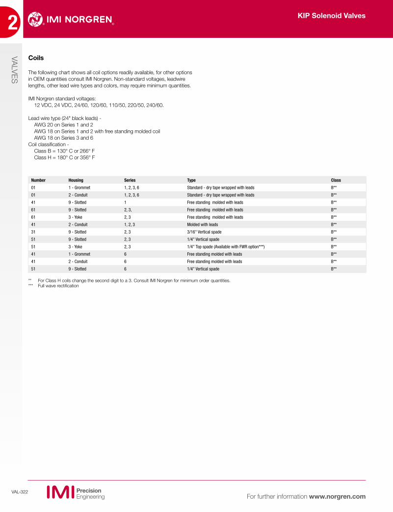
The following chart shows all coil options readily available, for other options in OEM quantities consult IMI Norgren. Non-standard voltages, leadwire lengths, other lead wire types and colors, may require minimum quantities.
IMI Norgren standard voltages: 12 VDC, 24 VDC, 24/60, 120/60, 110/50, 220/50, 240/60.
Lead wire type (24" black leads) - AWG 20 on Series 1 and 2 AWG 18 on Series 1 and 2 with free standing molded coil AWG 18 on Series 3 and 6
Coil classification - Class B = 130° C or 266° F Class H = 180° C or 356° F
** For Class H coils change the second digit to a 3. Consult IMI Norgren for minimum order quantities.*** Full wave rectification
Number Housing Series Type Class
01 1 - Grommet 1, 2, 3, 6 Standard - dry tape wrapped with leads B**
01 2 - Conduit 1, 2, 3, 6 Standard - dry tape wrapped with leads B**
41 9 - Slotted 1 Free standing molded with leads B**
61 9 - Slotted 2, 3, Free standing molded with leads B**
61 3 - Yoke 2, 3 Free standing molded with leads B**
41 2 - Conduit 1, 2, 3 Molded with leads B**
31 9 - Slotted 2, 3 3/16" Vertical spade B**
51 9 - Slotted 2, 3 1/4" Vertical spade B**
51 3 - Yoke 2, 3 1/4" Top spade (Available with FWR option***) B**
41 1 - Grommet 6 Free standing molded with leads B**
41 2 - Conduit 6 Free standing molded with leads B**
51 9 - Slotted 6 1/4" Vertical spade B**
KIP Solenoid Valves
VALVES
2
VAL-323For further information www.norgren.com
B KE
A DH
C
G
F
C D
A B
F
GE
K
Rectified CoilsThere may be times when you have a standard AC circuit but can’t have the copper shading ring which is standard in this type of valve due to media compatibility. Or, the application may be in a dirty or dusty environment where particulate causes the valve to buzz. In either case, a rectified coil will solve this problem. By adding two diodes in the coil (for half-wave rectification), or four diodes (for full-wave rectification), the effective voltage to the coil is modified from AC to DC. These rectified coils do not need any shading ring and perform as a DC coil with your standard AC input. The actual coil construction is designed for this type of rectification so you must contact the factory for ordering information. Since the addition of the diodes can make the physical size of the coil larger, it is not available in all types of coil and valve series. However, the rectification can take place away from the coil, such as on the customer’s electronics, within their equipment. Consult technical support for available options.
Arc SuppressionWhen DC voltage is disconnected from a solenoid valve, the coil reacts by generating its own voltage and sending a “spike" through the circuit. Depending on the size of the coil and the number of amp turns it contains, this generated voltage can be very high. In order to suppress this “spike" and protect other sensitive components in the electronic system, a diode is connected in parallel to the coils. Once the diode is placed in the coil it will now have a polarity. Since the diode only conducts in one direction the polarity of the coil must be maintained so as not to burn out the diode and eliminate the protection it is meant to provide. For ordering data and coil availability, contact technical support.
Rectified Coils and Coils with Arc Suppression Diodes
COIL DIODE
SWITCH
POWERSOURCE
–
+ –
+
COIL DIODE
SWITCH
POWERSOURCE
–
+ –
+
COIL
+
0
-
+
0
-
=
AC Sign Wave Rectified AC Input
Vertical Spade Coil
Top Spade Coil
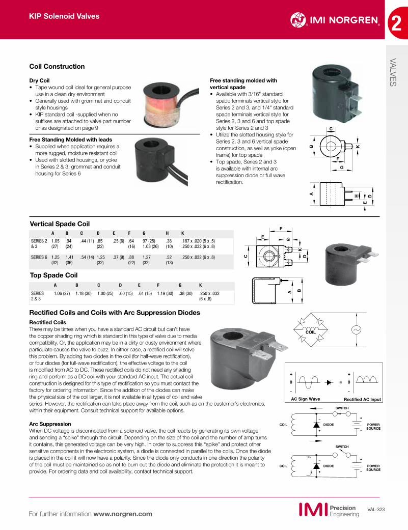
Free standing molded with vertical spade• Available with 3/16" standard
spade terminals vertical style for Series 2 and 3, and 1/4" standard spade terminals vertical style for Series 2, 3 and 6 and top spade style for Series 2 and 3
• Utilize the slotted housing style for Series 2, 3 and 6 vertical spade construction, as well as yoke (open frame) for top spade
• Top spade, Series 2 and 3 is available with internal arc suppression diode or full wave rectification.
A B C D E F G H K
SERIES 2 & 3
1.05 (27)
.94 (24)
.44 (11) .85 (22)
.25 (6) .64 (16)
97 (25) 1.03 (26)
.38 (10)
.187 x .020 (5 x .5)
.250 x .032 (6 x .8)
SERIES 6 1.25 (32)
1.41 (36)
.54 (14) 1.25 (32)
.37 (9) .88 (22)
1.27 (32)
.52 (13)
.250 x .032 (6 x .8)
A B C D E F G K
SERIES 2 & 3
1.06 (27) 1.18 (30) 1.00 (25) .60 (15) .61 (15) 1.19 (30) .38 (30) .250 x .032 (6 x .8)
Coil Construction
Dry Coil• Tape wound coil ideal for general purpose
use in a clean dry environment• Generally used with grommet and conduit
style housings• KIP standard coil -supplied when no
suffixes are attached to valve part number or as designated on page 9
Free Standing Molded with leads• Supplied when application requires a
more rugged, moisture resistant coil• Used with slotted housings, or yoke
in Series 2 & 3; grommet and conduit housing for Series 6
KIP Solenoid Valves
2
VALVES
VAL-324For further information www.norgren.com
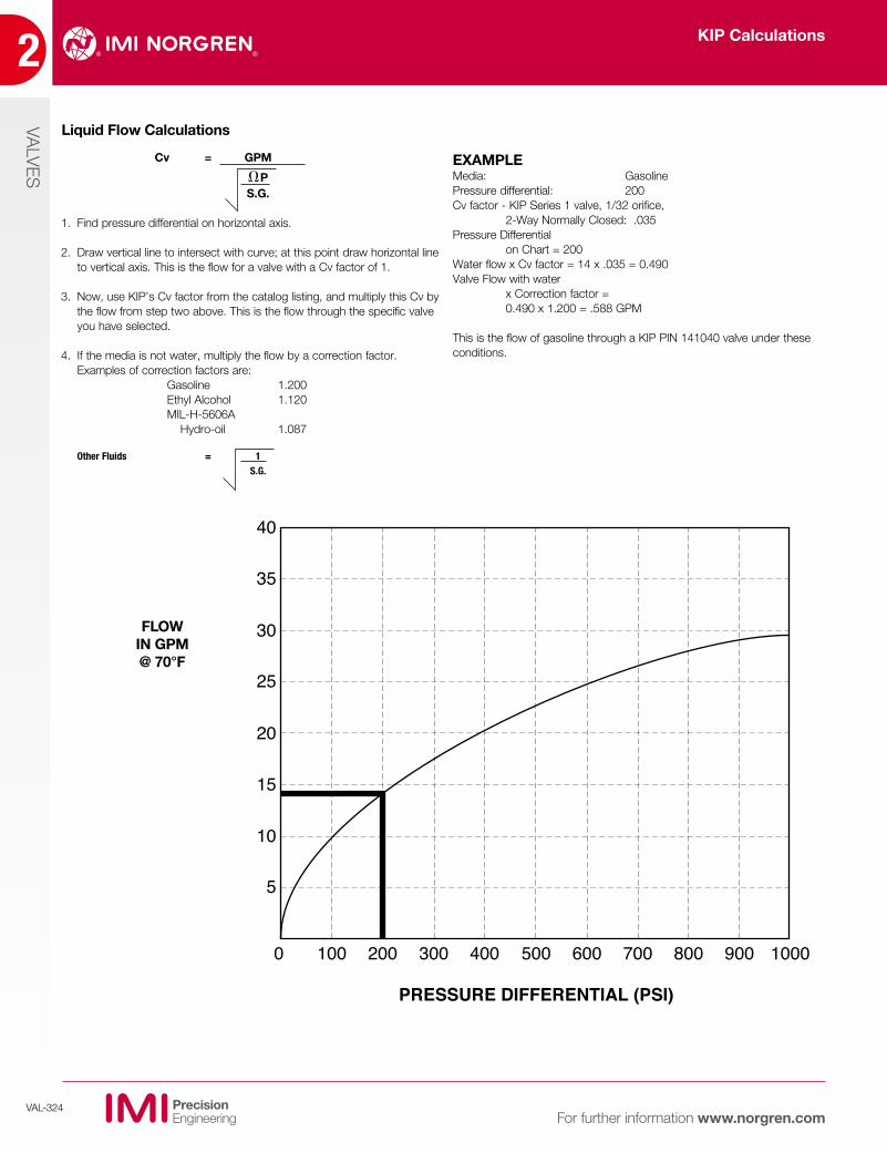
Cv = GPM
P S.G.
1. Find pressure differential on horizontal axis.
2. Draw vertical line to intersect with curve; at this point draw horizontal line to vertical axis. This is the flow for a valve with a Cv factor of 1.
3. Now, use KIP’s Cv factor from the catalog listing, and multiply this Cv by the flow from step two above. This is the flow through the specific valve you have selected.
4. If the media is not water, multiply the flow by a correction factor. Examples of correction factors are:
Gasoline 1.200 Ethyl Alcohol 1.120 MIL-H-5606A Hydro-oil 1.087
Other Fluids = 1 S.G.
0
5
10
15
20
25
30
35
40
100 200 300 400 500
PRESSURE DIFFERENTIAL (PSI)
600 700 800 900 1000
FLOW IN GPM @ 70°F
Liquid Flow Calculations
EXAMPLEMedia: GasolinePressure differential: 200Cv factor - KIP Series 1 valve, 1/32 orifice, 2-Way Normally Closed: .035Pressure Differential on Chart = 200Water flow x Cv factor = 14 x .035 = 0.490Valve Flow with water x Correction factor = 0.490 x 1.200 = .588 GPM
This is the flow of gasoline through a KIP PIN 141040 valve under these conditions.
KIP Calculations
VALVES
2
VAL-325For further information www.norgren.com
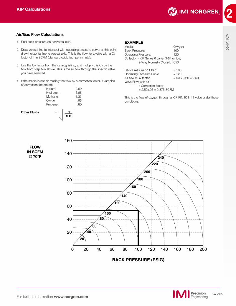
Air/Gas Flow Calculations
1. Find back pressure on horizontal axis.
2. Draw vertical line to intersect with operating pressure curve; at this point draw horizontal line to vertical axis. This is the flow for a valve with a Cv factor of 1 in SCFM (standard cubic feet per minute).
3. Use the Cv factor from the catalog listing, and multiply this Cv by the flow from step two above. This is the air flow through the specific valve you have selected.
4. If the media is not air multiply the flow by a correction factor. Examples of correction factors are:
Helium 2.69 Hydrogen 3.85 Methane 1.33 Oxygen .95 Propane .80
Other Fluids = 1 S.G.
0
20
40
60
80
100
120
140
160
20
20
4060
80100
120
140
160
180
200
220240
40 60 80 100
BACK PRESSURE (PSIG)
120 140 160 180 200
FLOW IN SCFM @ 70°F
EXAMPLEMedia: OxygenBack Pressure: 100Operating Pressure: 120Cv factor - KIP Series 6 valve, 3/64 orifice, 2-Way Normally Closed: .050
Back Pressure on Chart = 100Operating Pressure Curve = 120Air flow x Cv factor = 50 x .050 = 2.50Valve Flow with air x Correction factor = 2.50x.95 = 2.375 SCFM
This is the flow of oxygen through a KIP PIN 651111 valve under these conditions.
KIP Calculations
2
VALVES
VAL-326For further information www.norgren.com
Adapter Hexagonal-shaped brass, stainless steel or plated leadloy part for attaching stop port on the valve to the piping system.
Bubbletight A sealing capability within the valve which is undetectable during a 10-se-cond soap bubble test. Approximately = 2 x 10⁻³ cc/min on air.
Burst Pressure The point at which pressure containing parts rupture or breakdown causing an external leak.
Cv Value A value which indicates relative flow capacity of a valve, defined as the gallons of water per minute (GPM) at 60ºF which will flow through the valve with a pressure drop of 1 psi.
Coil Voltage Voltage at which the coil must be energized if the valve is to perform as stated in the specifications. KIP coils are designed to operate at +10% or -15% of rated voltage.
Continuous Duty A rating given a coil working under normal conditions that can be used continuously, without overheating or failure.
De-energized No current is flowing through the coil. Return spring holds the plunger against the body orifice. A normally closed valve is de-energized in the closed position.
Differential Pressure Pressure difference between the inlet line and the outlet line; i.e. 100 psig operating – 80 psig back = 20 psid.
Energized Current is flowing through the coil. The magnetic flux resulting from electricity passing through the coil forces the plunger to pull up against the end stop. When a normally closed valve is energized, the valve opens and stays open until the electrical current stops.
Heat Rise Difference between the temperature of the solenoid coil when de-energized and energized. KIP’s standard coils are Class B construction (130ºC max. temperature). Total Temperature = Ambient Temperature + Internal Coil Heatrise (KIP’s are 90ºC typically) If the ambient temperature were 70ºC, the total temperature would be 160ºC and the application would require a coil with Class H construction (180ºC max. temperature) as opposed to the Class B construction.
Intermittent Duty A rating given to a coil whose heat rise is too high for continuous duty. By using the coil with minimum “on” time, the coil will not reach extreme tem-peratures which would cause the valve not to operate or to fail prematurely.
MOPD (Maximum Operating Pressure Differential) The maximum difference in pressure, psi (lbs per square inch), between the valve inlet and outlet at which the solenoid can safely operate the valve.
Media The material that passes through the valve ports. Typical media include air, gases, water, hydraulic fluids, petroleum products, corrosive and noncorro-sive liquids.
Metering An adjustable pin which regulates the flow of media over a specified path; placed as a restriction in the media path.
Orifice Openings within the valve which can be open or closed to control the passage of media.
Oxygen Service Solenoid valves specified for use with oxygen require special cleaning and are furnished free of any oils or contaminants
Port Openings through which media entering (inlet) and exiting (outlet) the valve flow into and out of the valve.
Response Time The time necessary for a closed valve to fully open, or for an open valve to totally close. Response time is affected by voltage, pressure, size and media. The typical response time for KIP solenoid valves is 6 to 12 millise-conds.
Shading Ring Usually, a ring of copper pressed into a groove machined in the endstop of all alternating current (AC) valves. The ring overcomes oscillation and chatter associated with AC valves. Other materials typically used are silver and aluminum.
Key Terms
VALVES
2
VAL-327For further information www.norgren.com
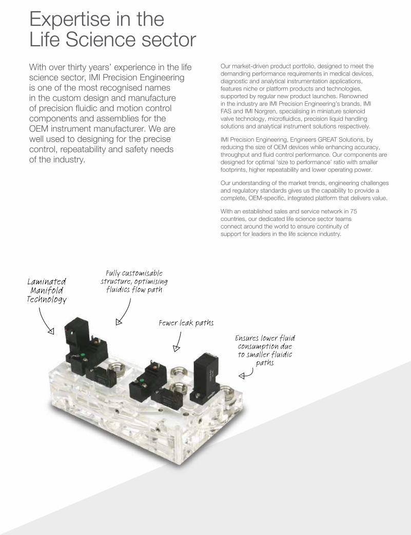
Fully customisable structure, optimising
fluidics flow path
Fewer leak paths
Laminated Manifold
Technology
Ensures lower fluid consumption due to smaller fluidic
paths
With over thirty years’ experience in the life science sector, IMI Precision Engineering is one of the most recognised names in the custom design and manufacture of precision fluidic and motion control components and assemblies for the OEM instrument manufacturer. We are well used to designing for the precise control, repeatability and safety needs of the industry.
Our market-driven product portfolio, designed to meet the demanding performance requirements in medical devices, diagnostic and analytical instrumentation applications, features niche or platform products and technologies, supported by regular new product launches. Renowned in the industry are IMI Precision Engineering’s brands, IMI FAS and IMI Norgren, specialising in miniature solenoid valve technology, microfluidics, precision liquid handling solutions and analytical instrument solutions respectively.
IMI Precision Engineering, Engineers GREAT Solutions, by reducing the size of OEM devices while enhancing accuracy, throughput and fluid control performance. Our components are designed for optimal ‘size to performance’ ratio with smaller footprints, higher repeatability and lower operating power.
Our understanding of the market trends, engineering challenges and regulatory standards gives us the capability to provide a complete, OEM-specific, integrated platform that delivers value.
With an established sales and service network in 75 countries, our dedicated life science sector teams connect around the world to ensure continuity of support for leaders in the life science industry.
Expertise in the Life Science sector


![‘H’ Series 3 and 5 Valve Differential Pressure Manifolds Series 3 and 5...‘H’ series 3 and 5 valve manifolds 3 >P[O `LHYZ VM THUPMVSK KLZPNU HUK KL]LSVWTLU[ L_WLYPLUJL 7HYRLY](https://img.pdfslide.us/doc/110x75/5ff2ac9053af5c096a11dfe5/aha-series-3-and-5-valve-differential-pressure-manifolds-series-3-and-5-aha.jpg)


![[PL 006-152] 1-, 2-, 3-, and 5-Valve Manifolds for Use](https://img.pdfslide.us/doc/110x75/615a8c100ed2042dcd79e639/pl-006-152-1-2-3-and-5-valve-manifolds-for-use-.jpg)