Embed Size (px)
Citation preview
copy Danfoss | DCS (az) | 201810 DKRCCPDDA03A02 | 1
Data sheet
Pressure operated water valve Type WVFX and WVS
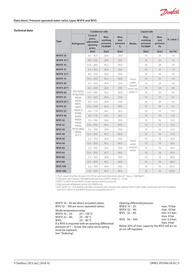
Pressure operated water valves types WVFX and WVS are used for regulating the flow of water in refrigeration plants with water-cooled condensers
The pressure operated water valves give modulating regulation of the condensing pressure within defined limits during operation When the refrigeration plant is stopped the cooling water flow is shut off automatically
Pressure operated water valves can be used with flammable refrigerants Double sealing between the refrigerant and the water line ensures that in case the bellows damage and the refrigerant leak it cannot enter into the water This severely limits the safety implications It means that the valve can be used together with a double walled heat exchanger and water circuit in such a system does not need to be considered as a part of the installation for flammable refrigerants (EN378-12008 clause 4422)
Features bull Media Fresh water and Neutral brinebull Refrigerants HCFC HFC and HCbull Needs no power supply ndash self actingbull Opens on rising condensing pressurebull Complete flow range from 14 ndash 300 m3hbull Low flow version of WVFX ndash 063 m3h
(available on request)
bull Insensitive to dirtbull WVFX 10 ndash 25 are available in stainless steel
housingbull Suitable for flammable refrigerantsbull May be used in the following EX range
Category 3 (Zone 2)
copy Danfoss | DCS (az) | 201810
Data sheet | Pressure operated water valve types WVFX and WVS
DKRCCPDDA03A02 | 2
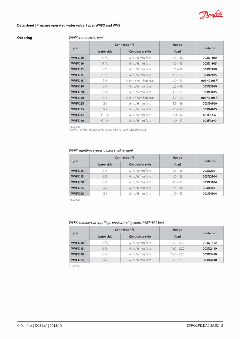
Technical data
1) The Kv value is the flow of water in [m3h] at a pressure drop across valve of 1 bar ρ = 1000 kgm32) Fully open valve requires 33 higher pressure than a WVFX range 35 ndash 16 bar3) WVFX 15 WVFX 20 and WVFX 25 with stainless steel housing only4) High pressure refrigerants version (452 MWP) only5) WVS WVFX 10 ndash 25 and WVO with flare connection only versions with capillary tube or with solder connections are not compatible with R717 WVFX 32 and WVFX 40 are not compatible with R717
WVFX 10 ndash 40 are direct actuated valves WVS 32 ndash 100 are servo-operated valves
Media temperature range WVFX 10 ndash 25 -25 ndash 130 degC WVFX 32 ndash 40 -25 ndash 90 degC WVS -25 ndash 90 degC If a WVS is required with an opening differential pressure of 1 ndash 10 bar the valve servo spring must be replaced See ldquoOrderingrdquo
Opening differential pressure WVFX 10 ndash 25 max 10 bar WVFX 32 ndash 40 max 10 bar WVS 32 ndash 40 min 05 bar max 4 bar WVS 50 ndash 100 min 03 bar max 4 bar Below 20 of max capacity the WVS will act as an on-off regulator
Type
Condenser side Liquid side
Kv value 1)
Refrigerant
Control press
adjustable opening
press
Max working pressurePSMWP
Max test
pressurePe
Media
Max working pressure PSMWP
Maxtest
pressurePe
[bar] [bar] [bar] [bar] [bar] [m3h]
WVFX 10
R22 R1270 R134a R290
R404A R407A R407C R407F
R410A 4) R448A R449A R450A R452A R507A
R513A R600 R600a R717 5)
35 ndash 160 264 290
Fresh water
neutral brine sea water 3)
16 24 14
WVFX 10 2) 40 ndash 230 264 290 16 24 14
WVFX 10 150 ndash 290 452 600 16 24 14
WVFX 15 35 ndash 160 264 290 16 24 19
WVFX 15 2) 40 ndash 230 264 290 16 24 19
WVFX 15 150 ndash 290 452 600 16 24 19
WVFX 20 35 ndash 160 264 290 16 24 34
WVFX 20 2) 40 ndash 230 264 290 16 24 34
WVFX 20 150 ndash 290 452 600 16 24 34
WVFX 25 35 ndash 160 264 290 16 24 55
WVFX 25 2) 40 ndash 230 264 290 16 24 55
WVFX 25 150 ndash 290 452 600 16 24 55
WVFX 32 40 ndash 170 241 265 10 10 110
WVFX 40 40 ndash 170 241 265 10 10 110
WVS 32 22 ndash 190 264 290
Fresh water
neutral brine
10 16 125
WVS 32 150 ndash 290 452 600 10 16 125
WVS 40 22 ndash 190 264 290 10 16 210
WVS 40 150 ndash 290 452 600 10 16 210
WVS 50 22 ndash 190 264 290 10 16 320
WVS 50 150 ndash 290 452 600 10 16 320
WVS 65 22 ndash 190 264 290 10 16 450
WVS 65 150 ndash 290 452 600 10 16 450
WVS 80 22 ndash 190 264 290 10 16 800
WVS 80 150 ndash 290 452 600 10 16 800
WVS 100 22 ndash 190 264 290 10 16 1250
WVS 100 150 ndash 290 452 600 10 16 1250
copy Danfoss | DCS (az) | 201810
Data sheet | Pressure operated water valve types WVFX and WVS
DKRCCPDDA03A02 | 3
1) ISO 228-12) WVFX 15 with 1 m capillary tube and flare nut with valve depressor
TypeConnection 1) Range
Code noWater side Condenser side [bar]
WVFX 10 G sup3frasl₈ frac14 in 6 mm flare 35 ndash 16 003N1100
WVFX 10 G sup3frasl₈ frac14 in 6 mm flare 40 ndash 23 003N1105
WVFX 15 G frac12 frac14 in 6 mm flare 35 ndash 16 003N2100
WVFX 15 G frac12 frac14 in 6 mm flare 40 ndash 23 003N2105
WVFX 15 G frac12 frac14 in 6 mm flare nut 40 ndash 23 003N2205 2)
WVFX 20 G frac34 frac14 in 6 mm flare 35 ndash 16 003N3100
WVFX 20 G frac34 frac14 in 6 mm flare 40 ndash 23 003N3105
WVFX 20 G frac34 frac14 in 6 mm flare nut 40 ndash 23 003N3205 2)
WVFX 25 G 1 frac14 in 6 mm flare 35 ndash 16 003N4100
WVFX 25 G 1 frac14 in 6 mm flare 40 ndash 23 003N4105
WVFX 32 G 1 frac14 frac14 in 6 mm flare 40 ndash 17 003F1232
WVFX 40 G 1 frac12 frac14 in 6 mm flare 40 ndash 17 003F1240
Ordering WVFX commercial type
WVFX maritime type (stainless steel version)
WVFX commercial type (high pressure refrigerants MWP 452 bar)
TypeConnection 1) Range
Code noWater side Condenser side [bar]
WVFX 15 G frac12 frac14 in 6 mm flare 35 ndash 16 003N2101
WVFX 15 G frac12 frac14 in 6 mm flare 40 ndash 23 003N2104
WVFX 20 G frac34 frac14 in 6 mm flare 40 ndash 23 003N3104
WVFX 25 G 1 frac14 in 6 mm flare 35 ndash 16 003N4101
WVFX 25 G 1 frac14 in 6 mm flare 40 ndash 23 003N4104
TypeConnection 1) Range
Code noWater side Condenser side [bar]
WVFX 10 G sup3frasl₈ frac14 in 6 mm flare 150 ndash 290 003N1410
WVFX 15 G frac12 frac14 in 6 mm flare 150 ndash 290 003N2410
WVFX 20 G frac34 frac14 in 6 mm flare 150 ndash 290 003N3410
WVFX 25 G 1 frac14 in 6 mm flare 150 ndash 290 003N4410
1) ISO 228-1
1) ISO 228-1
copy Danfoss | DCS (az) | 201810
Data sheet | Pressure operated water valve types WVFX and WVS
DKRCCPDDA03A02 | 4
Type Connection 1)
Code no
Valve body Pilot unit 3)Pilot unit for
R410A andR744 3)
Flange set 4)
Servo spring for differential
pressure range of 1 ndash 10 bar
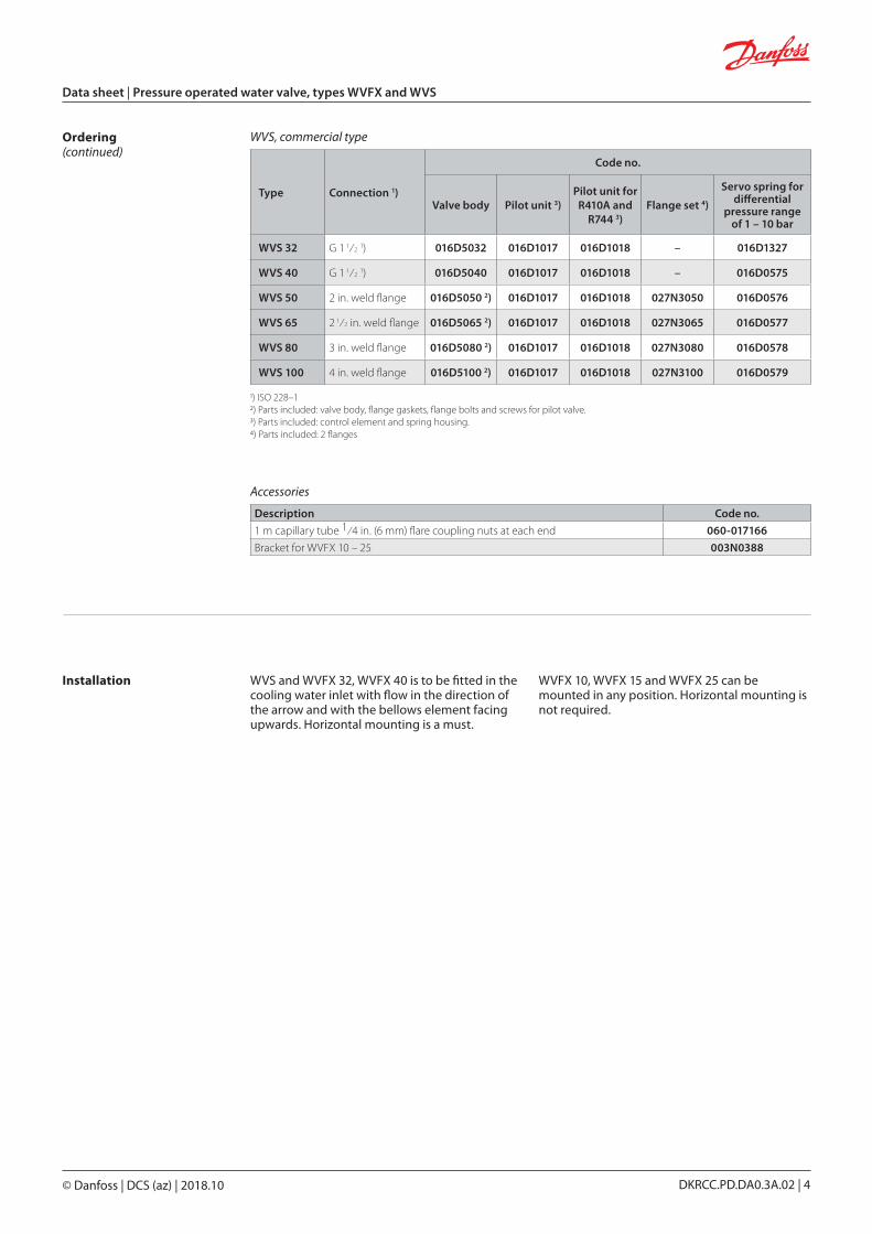
WVS 32 G 1 1frasl2 1) 016D5032 016D1017 016D1018 ndash 016D1327
WVS 40 G 1 1frasl2 1) 016D5040 016D1017 016D1018 ndash 016D0575
WVS 50 2 in weld flange 016D5050 2) 016D1017 016D1018 027N3050 016D0576
WVS 65 2 1frasl2 in weld flange 016D5065 2) 016D1017 016D1018 027N3065 016D0577
WVS 80 3 in weld flange 016D5080 2) 016D1017 016D1018 027N3080 016D0578
WVS 100 4 in weld flange 016D5100 2) 016D1017 016D1018 027N3100 016D0579
Description Code no
1 m capillary tube 1frasl4 in (6 mm) flare coupling nuts at each end 060-017166
Bracket for WVFX 10 ndash 25 003N0388
WVS commercial type
Accessories
1) ISO 228ndash12) Parts included valve body flange gaskets flange bolts and screws for pilot valve 3) Parts included control element and spring housing4) Parts included 2 flanges
Ordering (continued)
Installation WVS and WVFX 32 WVFX 40 is to be fitted in the cooling water inlet with flow in the direction of the arrow and with the bellows element facing upwards Horizontal mounting is a must
WVFX 10 WVFX 15 and WVFX 25 can be mounted in any position Horizontal mounting is not required
copy Danfoss | DCS (az) | 201810
[bar]
[m3h]
Data sheet | Pressure operated water valve types WVFX and WVS
DKRCCPDDA03A02 | 5
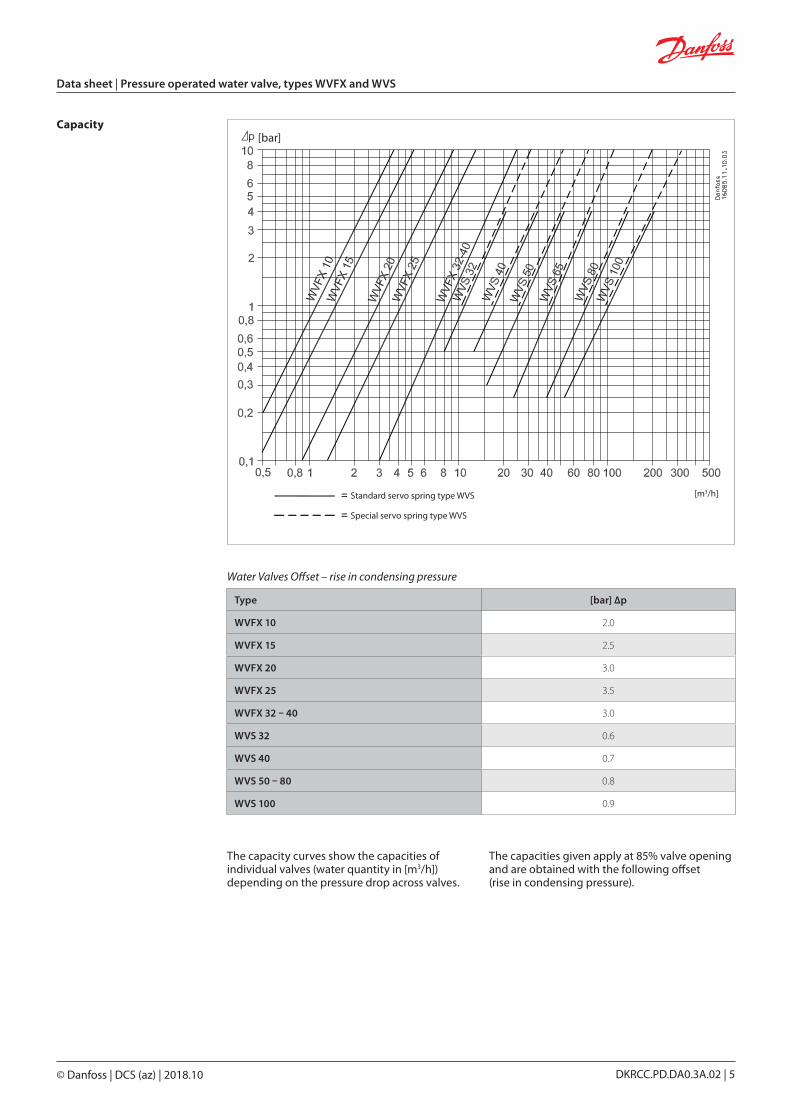
Type [bar] ∆p
WVFX 10 20
WVFX 15 25
WVFX 20 30
WVFX 25 35
WVFX 32 ndash 40 30
WVS 32 06
WVS 40 07
WVS 50 ndash 80 08
WVS 100 09
Capacity
The capacity curves show the capacities of individual valves (water quantity in [m3h]) depending on the pressure drop across valves
The capacities given apply at 85 valve opening and are obtained with the following offset (rise in condensing pressure)
Standard servo spring type WVS
Special servo spring type WVS
Water Valves Offset ndash rise in condensing pressure
copy Danfoss | DCS (az) | 201810
WVFX 10 ndash 25
WVFX 32 ndash 40
Data sheet | Pressure operated water valve types WVFX and WVS
DKRCCPDDA03A02 | 6
Design Function Condensing pressure impulses are transmitted via the bellows element to the valve cone so that the valve ndash even at very small pressure variations ndash is able to adapt the quantity of water required by the condenser
The valves are pressure-relieved in such a way that a variation in the water pressure will not affect their setting
To protect the refrigeration plant against high head pressures in the event that the water supply to the condenser fails a safety switch type KP or RT should be fitted on the high pressure side
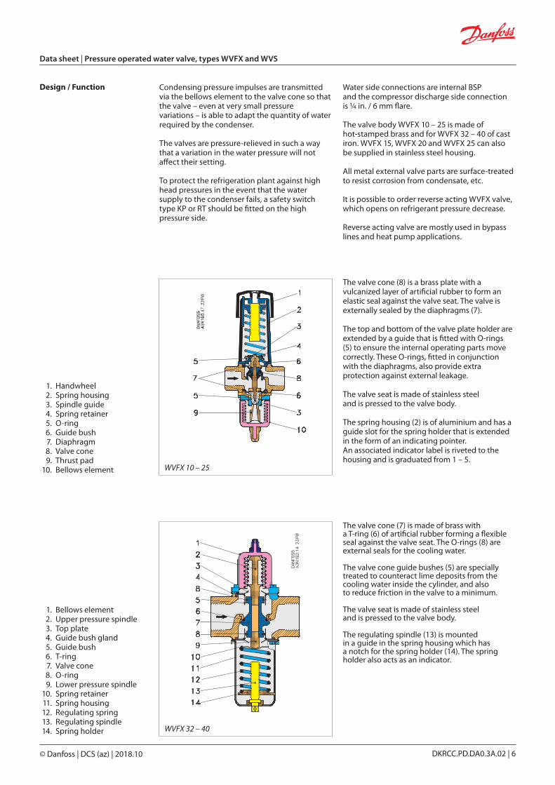
The valve cone (8) is a brass plate with a vulcanized layer of artificial rubber to form an elastic seal against the valve seat The valve is externally sealed by the diaphragms (7)
The top and bottom of the valve plate holder are extended by a guide that is fitted with O-rings (5) to ensure the internal operating parts move correctly These O-rings fitted in conjunction with the diaphragms also provide extra protection against external leakage
The valve seat is made of stainless steel and is pressed to the valve body
The spring housing (2) is of aluminium and has a guide slot for the spring holder that is extended in the form of an indicating pointer An associated indicator label is riveted to the housing and is graduated from 1 ndash 5
1 Handwheel 2 Spring housing 3 Spindle guide 4 Spring retainer 5 O-ring 6 Guide bush 7 Diaphragm 8 Valve cone 9 Thrust pad 10 Bellows element
The valve cone (7) is made of brass with a T-ring (6) of artificial rubber forming a flexible seal against the valve seat The O-rings (8) are external seals for the cooling water
The valve cone guide bushes (5) are specially treated to counteract lime deposits from the cooling water inside the cylinder and also to reduce friction in the valve to a minimum
The valve seat is made of stainless steel and is pressed to the valve body
The regulating spindle (13) is mounted in a guide in the spring housing which has a notch for the spring holder (14) The spring holder also acts as an indicator
1 Bellows element 2 Upper pressure spindle 3 Top plate 4 Guide bush gland 5 Guide bush 6 T-ring 7 Valve cone 8 O-ring 9 Lower pressure spindle 10 Spring retainer 11 Spring housing 12 Regulating spring 13 Regulating spindle 14 Spring holder
Water side connections are internal BSP and the compressor discharge side connection is frac14 in 6 mm flare
The valve body WVFX 10 ndash 25 is made of hot-stamped brass and for WVFX 32 ndash 40 of cast iron WVFX 15 WVFX 20 and WVFX 25 can also be supplied in stainless steel housing
All metal external valve parts are surface-treated to resist corrosion from condensate etc
It is possible to order reverse acting WVFX valve which opens on refrigerant pressure decrease
Reverse acting valve are mostly used in bypass lines and heat pump applications
copy Danfoss | DCS (az) | 201810
WVS 32
WVS 50 ndash 100
WVS 40
Data sheet | Pressure operated water valve types WVFX and WVS
DKRCCPDDA03A02 | 7
Design Function (continued)
1 Pressure connection (flare nipple)
2 Pressure connection (weld nipple)
3 Bellows element 4 Push rod 5 Regulating nut 6 Spring housing 6a Cover 7 Pilot assembly 8 Spindle for pilot cone 9 Teflon sleeves 10 Insulating gasket 10a Gasket 11 O-ring 12 Valve cover 13 O-ring 14 O-ring 15 Servo piston 16 Bottom screw 17 Drain plug 18 Gasket 19 Strainer assembly
complete 20 Self-cleaning strainer
assembly 21 Pilot orifice 22 Gasket 23 O-ring 24 Servo spring
WVS 32 ndash 40 valves have internal BSP connections while WVS 50 ndash 100 can be supplied with either BSP connections or weld flanges
Connection to the plant condenser can be made by copper tube or steel tube the valves being supplied with both a flare nipple for 1frasl4 in (6 mm) copper tube and a weld nipple for oslash6 mm oslash10 mm steel tube
The valve consists of three main components
1 Main valve with servo piston The main valve body is made of cast iron with a pressed-in bronze seat The servo piston is of gun metal and has a sleeve and a profiled rubber seal ring
2 Pilot valve The pilot valve is made of gun metal the pilot cone and seat of stainless steel and the pilot orifice of brass These materials are particularly resistant to water corrosion However the valve is not resistant to sea water
The strainer ahead of the pilot orifice is made of nickel gauze
The degree of opening of the pilot valve (which corresponds to the increase in condensing pressure above the set opening pressure) determines the degree of opening of the main valve and thereby amount of the water flow
3 Bellows unit with connection to condenser The bellows unit is made of aluminium and corrosion-proofed steel
copy Danfoss | DCS (az) | 201810
Data sheet | Pressure operated water valve types WVFX and WVS
DKRCCPDDA03A02 | 8
Necessary mass flow
Volume flow
Sizing When sizing and selecting water regulating valves it is most important to ensure that the valve at any time is able to give the necessary quantity of cooling water
To select a suitable size of valve it is necessary to know the precise amount of cooling required
On the other hand to avoid the risk of unstable regulation (hunting) the valve should not be oversized
In general the aim should be to select the smallest valve capable of giving the required flow
To obtain a precise control it can be recommended to only use 85 of the capacity Below 85 the ratio between flow and condensing difference pressure is linear Above 85 the ratio is no longer linear To reach a 100 capacity the water valve needs significant increase of condensing pressure See fig below
Valve size
Sizing Examples Example 1 Condenser capacity Q0 30 kW Condensing temperature t0 35 degC Refrigerant R404A Cooling media water
Specific heat capacity of water Cp 419 kj(kgK) Water inlet temperature t1 15 degC Water outlet temperature t2 25 degC Pressure drop across valve ∆p max 10 bar
m = Q
c
3600 = 30
3600 = 2577 kgh C
p ∙ (t2 ndash t1) 419 ∙ (25 ndash 15)
∙
V = m
= 2577
asymp 26 m3h ρ 1000
∙ ∙
Type ∆p offset [bar]
WVFX 10 20
WVFX 15 25
WVFX 20 30
WVFX 25 35
WVFX 32 ndash 40 30
WVS 32 06
WVS 40 07
WVS 50 ndash 80 08
WVS 100 09
The following data is used when selecting the size of the water valve
y Cooling capacity of condenser y Temperature rise in cooling media y Differential pressure across valve
y Condensing temperature y Specific heat capacity of cooling media y Refrigerant
Water Capacity
Condensing pressure
Offset
copy Danfoss | DCS (az) | 201810
[bar]
[m3h]
Data sheet | Pressure operated water valve types WVFX and WVS
DKRCCPDDA03A02 | 9
Example 2 Condenser capacity QC 20 kW Condensing temperature tC 35 degC Refrigerant R134a Cooling media Brine Density of brine ρ 1015 kgm3
Specific heat capacity of water Cp 435 kj(kgK) Water inlet temperature t1 20 degC Water outlet temperature t2 25 degC Pressure drop across valve ∆p max 20 bar
Selecting size
Necessary mass flow
Volume flow
Kv value
V = m
= 3310
asymp 326 m3h ρ 1015
∙ ∙
m = Qc
3600 =
20 3600 = 3310 kgh
Cp ∙ (t2 ndash t1) 435 ∙ (25 ndash 20)
Kv ge V
= 326
= 232 m3h 1000 ∙ ∆p 1000 ∙ 20
ρ 1015
∙
Selecting size of WVFX 20 Kv ge 232 m3h =gt WVFX 20 WVFX 20 has Kv = 34 m3h and the necessary capacity is below 85 of full capacity
Code number The saturated pressure for R134a Tc = 35 degC Pc = 79 barg
Choose a WVFX 20 with 35 ndash 16 barg range
Selecting WVFX 20 Code number The saturated pressure for R404A Tc = 35 degC =gt Pc = 155 barg
Choose a WVFX 20 with 4 ndash 23 barg range
Standard servo spring type WVS
Special servo spring type WVS
copy Danfoss | DCS (az) | 201810
56
22
Oslash4
Oslash715
40
25
62
15
9
50
Dan
foss
3N20
011
Dan
foss
3-19
315
FW
Dan
foss
16D
031
4 FW
Dan
foss
3N15
731
0 FW
Dan
foss
16D
691
4 FW
WVFX 10 ndash 25
WVFX 32 ndash 40 WVS 32 ndash 40
WVS 50 ndash 100
Data sheet | Pressure operated water valve types WVFX and WVS
DKRCCPDDA03A02 | 10
Dimensions [mm] and weights [kg] Bracket for WVFX 10 ndash 25
copy Danfoss | DCS (az) | 201810 DKRCCPDDA03A02 | 11
Dimensions [mm] and weights [kg] (continued) Type H1 H2 H3 L L1 B oslash
Net weight
WVFX 10 91 133 ndash 72 11 ndash 55 10
WVFX 15 91 133 ndash 72 14 ndash 55 10
WVFX 20 91 133 ndash 90 16 ndash 55 20
WVFX 25 96 138 ndash 95 19 ndash 55 20
WVS 32 42 243 234 138 20 85 ndash 40
WVS 40 72 271 262 198 30 100 ndash 70
WVS 50 78 277 268 315 218 ndash 165 190
WVS 65 82 293 284 320 224 ndash 185 240
WVS 80 90 325 316 370 265 ndash 200 340
WVS 100 100 345 336 430 315 ndash 220 440
Type H1 H2 H3 L L1 B oslashNet
weight
WVS 32 42 259 250 138 20 85 ndash 40
WVS 40 72 287 278 198 30 100 ndash 70
WVS 50 78 293 2684 315 218 ndash 165 190
WVS 65 82 309 300 320 224 ndash 185 240
WVS 80 90 341 332 370 265 ndash 200 340
WVS 100 100 361 352 430 315 ndash 220 440
Pressure operated water valve type WVS - high pressure refrigerants
Pressure operated water valve
copy Danfoss | DCS (az) | 201810
Data sheet | Pressure operated water valve types WVFX and WVS
DKRCCPDDA03A02 | 2
Technical data
1) The Kv value is the flow of water in [m3h] at a pressure drop across valve of 1 bar ρ = 1000 kgm32) Fully open valve requires 33 higher pressure than a WVFX range 35 ndash 16 bar3) WVFX 15 WVFX 20 and WVFX 25 with stainless steel housing only4) High pressure refrigerants version (452 MWP) only5) WVS WVFX 10 ndash 25 and WVO with flare connection only versions with capillary tube or with solder connections are not compatible with R717 WVFX 32 and WVFX 40 are not compatible with R717
WVFX 10 ndash 40 are direct actuated valves WVS 32 ndash 100 are servo-operated valves
Media temperature range WVFX 10 ndash 25 -25 ndash 130 degC WVFX 32 ndash 40 -25 ndash 90 degC WVS -25 ndash 90 degC If a WVS is required with an opening differential pressure of 1 ndash 10 bar the valve servo spring must be replaced See ldquoOrderingrdquo
Opening differential pressure WVFX 10 ndash 25 max 10 bar WVFX 32 ndash 40 max 10 bar WVS 32 ndash 40 min 05 bar max 4 bar WVS 50 ndash 100 min 03 bar max 4 bar Below 20 of max capacity the WVS will act as an on-off regulator
Type
Condenser side Liquid side
Kv value 1)
Refrigerant
Control press
adjustable opening
press
Max working pressurePSMWP
Max test
pressurePe
Media
Max working pressure PSMWP
Maxtest
pressurePe
[bar] [bar] [bar] [bar] [bar] [m3h]
WVFX 10
R22 R1270 R134a R290
R404A R407A R407C R407F
R410A 4) R448A R449A R450A R452A R507A
R513A R600 R600a R717 5)
35 ndash 160 264 290
Fresh water
neutral brine sea water 3)
16 24 14
WVFX 10 2) 40 ndash 230 264 290 16 24 14
WVFX 10 150 ndash 290 452 600 16 24 14
WVFX 15 35 ndash 160 264 290 16 24 19
WVFX 15 2) 40 ndash 230 264 290 16 24 19
WVFX 15 150 ndash 290 452 600 16 24 19
WVFX 20 35 ndash 160 264 290 16 24 34
WVFX 20 2) 40 ndash 230 264 290 16 24 34
WVFX 20 150 ndash 290 452 600 16 24 34
WVFX 25 35 ndash 160 264 290 16 24 55
WVFX 25 2) 40 ndash 230 264 290 16 24 55
WVFX 25 150 ndash 290 452 600 16 24 55
WVFX 32 40 ndash 170 241 265 10 10 110
WVFX 40 40 ndash 170 241 265 10 10 110
WVS 32 22 ndash 190 264 290
Fresh water
neutral brine
10 16 125
WVS 32 150 ndash 290 452 600 10 16 125
WVS 40 22 ndash 190 264 290 10 16 210
WVS 40 150 ndash 290 452 600 10 16 210
WVS 50 22 ndash 190 264 290 10 16 320
WVS 50 150 ndash 290 452 600 10 16 320
WVS 65 22 ndash 190 264 290 10 16 450
WVS 65 150 ndash 290 452 600 10 16 450
WVS 80 22 ndash 190 264 290 10 16 800
WVS 80 150 ndash 290 452 600 10 16 800
WVS 100 22 ndash 190 264 290 10 16 1250
WVS 100 150 ndash 290 452 600 10 16 1250
copy Danfoss | DCS (az) | 201810
Data sheet | Pressure operated water valve types WVFX and WVS
DKRCCPDDA03A02 | 3
1) ISO 228-12) WVFX 15 with 1 m capillary tube and flare nut with valve depressor
TypeConnection 1) Range
Code noWater side Condenser side [bar]
WVFX 10 G sup3frasl₈ frac14 in 6 mm flare 35 ndash 16 003N1100
WVFX 10 G sup3frasl₈ frac14 in 6 mm flare 40 ndash 23 003N1105
WVFX 15 G frac12 frac14 in 6 mm flare 35 ndash 16 003N2100
WVFX 15 G frac12 frac14 in 6 mm flare 40 ndash 23 003N2105
WVFX 15 G frac12 frac14 in 6 mm flare nut 40 ndash 23 003N2205 2)
WVFX 20 G frac34 frac14 in 6 mm flare 35 ndash 16 003N3100
WVFX 20 G frac34 frac14 in 6 mm flare 40 ndash 23 003N3105
WVFX 20 G frac34 frac14 in 6 mm flare nut 40 ndash 23 003N3205 2)
WVFX 25 G 1 frac14 in 6 mm flare 35 ndash 16 003N4100
WVFX 25 G 1 frac14 in 6 mm flare 40 ndash 23 003N4105
WVFX 32 G 1 frac14 frac14 in 6 mm flare 40 ndash 17 003F1232
WVFX 40 G 1 frac12 frac14 in 6 mm flare 40 ndash 17 003F1240
Ordering WVFX commercial type
WVFX maritime type (stainless steel version)
WVFX commercial type (high pressure refrigerants MWP 452 bar)
TypeConnection 1) Range
Code noWater side Condenser side [bar]
WVFX 15 G frac12 frac14 in 6 mm flare 35 ndash 16 003N2101
WVFX 15 G frac12 frac14 in 6 mm flare 40 ndash 23 003N2104
WVFX 20 G frac34 frac14 in 6 mm flare 40 ndash 23 003N3104
WVFX 25 G 1 frac14 in 6 mm flare 35 ndash 16 003N4101
WVFX 25 G 1 frac14 in 6 mm flare 40 ndash 23 003N4104
TypeConnection 1) Range
Code noWater side Condenser side [bar]
WVFX 10 G sup3frasl₈ frac14 in 6 mm flare 150 ndash 290 003N1410
WVFX 15 G frac12 frac14 in 6 mm flare 150 ndash 290 003N2410
WVFX 20 G frac34 frac14 in 6 mm flare 150 ndash 290 003N3410
WVFX 25 G 1 frac14 in 6 mm flare 150 ndash 290 003N4410
1) ISO 228-1
1) ISO 228-1
copy Danfoss | DCS (az) | 201810
Data sheet | Pressure operated water valve types WVFX and WVS
DKRCCPDDA03A02 | 4
Type Connection 1)
Code no
Valve body Pilot unit 3)Pilot unit for
R410A andR744 3)
Flange set 4)
Servo spring for differential
pressure range of 1 ndash 10 bar
WVS 32 G 1 1frasl2 1) 016D5032 016D1017 016D1018 ndash 016D1327
WVS 40 G 1 1frasl2 1) 016D5040 016D1017 016D1018 ndash 016D0575
WVS 50 2 in weld flange 016D5050 2) 016D1017 016D1018 027N3050 016D0576
WVS 65 2 1frasl2 in weld flange 016D5065 2) 016D1017 016D1018 027N3065 016D0577
WVS 80 3 in weld flange 016D5080 2) 016D1017 016D1018 027N3080 016D0578
WVS 100 4 in weld flange 016D5100 2) 016D1017 016D1018 027N3100 016D0579
Description Code no
1 m capillary tube 1frasl4 in (6 mm) flare coupling nuts at each end 060-017166
Bracket for WVFX 10 ndash 25 003N0388
WVS commercial type
Accessories
1) ISO 228ndash12) Parts included valve body flange gaskets flange bolts and screws for pilot valve 3) Parts included control element and spring housing4) Parts included 2 flanges
Ordering (continued)
Installation WVS and WVFX 32 WVFX 40 is to be fitted in the cooling water inlet with flow in the direction of the arrow and with the bellows element facing upwards Horizontal mounting is a must
WVFX 10 WVFX 15 and WVFX 25 can be mounted in any position Horizontal mounting is not required
copy Danfoss | DCS (az) | 201810
[bar]
[m3h]
Data sheet | Pressure operated water valve types WVFX and WVS
DKRCCPDDA03A02 | 5
Type [bar] ∆p
WVFX 10 20
WVFX 15 25
WVFX 20 30
WVFX 25 35
WVFX 32 ndash 40 30
WVS 32 06
WVS 40 07
WVS 50 ndash 80 08
WVS 100 09
Capacity
The capacity curves show the capacities of individual valves (water quantity in [m3h]) depending on the pressure drop across valves
The capacities given apply at 85 valve opening and are obtained with the following offset (rise in condensing pressure)
Standard servo spring type WVS
Special servo spring type WVS
Water Valves Offset ndash rise in condensing pressure
copy Danfoss | DCS (az) | 201810
WVFX 10 ndash 25
WVFX 32 ndash 40
Data sheet | Pressure operated water valve types WVFX and WVS
DKRCCPDDA03A02 | 6
Design Function Condensing pressure impulses are transmitted via the bellows element to the valve cone so that the valve ndash even at very small pressure variations ndash is able to adapt the quantity of water required by the condenser
The valves are pressure-relieved in such a way that a variation in the water pressure will not affect their setting
To protect the refrigeration plant against high head pressures in the event that the water supply to the condenser fails a safety switch type KP or RT should be fitted on the high pressure side
The valve cone (8) is a brass plate with a vulcanized layer of artificial rubber to form an elastic seal against the valve seat The valve is externally sealed by the diaphragms (7)
The top and bottom of the valve plate holder are extended by a guide that is fitted with O-rings (5) to ensure the internal operating parts move correctly These O-rings fitted in conjunction with the diaphragms also provide extra protection against external leakage
The valve seat is made of stainless steel and is pressed to the valve body
The spring housing (2) is of aluminium and has a guide slot for the spring holder that is extended in the form of an indicating pointer An associated indicator label is riveted to the housing and is graduated from 1 ndash 5
1 Handwheel 2 Spring housing 3 Spindle guide 4 Spring retainer 5 O-ring 6 Guide bush 7 Diaphragm 8 Valve cone 9 Thrust pad 10 Bellows element
The valve cone (7) is made of brass with a T-ring (6) of artificial rubber forming a flexible seal against the valve seat The O-rings (8) are external seals for the cooling water
The valve cone guide bushes (5) are specially treated to counteract lime deposits from the cooling water inside the cylinder and also to reduce friction in the valve to a minimum
The valve seat is made of stainless steel and is pressed to the valve body
The regulating spindle (13) is mounted in a guide in the spring housing which has a notch for the spring holder (14) The spring holder also acts as an indicator
1 Bellows element 2 Upper pressure spindle 3 Top plate 4 Guide bush gland 5 Guide bush 6 T-ring 7 Valve cone 8 O-ring 9 Lower pressure spindle 10 Spring retainer 11 Spring housing 12 Regulating spring 13 Regulating spindle 14 Spring holder
Water side connections are internal BSP and the compressor discharge side connection is frac14 in 6 mm flare
The valve body WVFX 10 ndash 25 is made of hot-stamped brass and for WVFX 32 ndash 40 of cast iron WVFX 15 WVFX 20 and WVFX 25 can also be supplied in stainless steel housing
All metal external valve parts are surface-treated to resist corrosion from condensate etc
It is possible to order reverse acting WVFX valve which opens on refrigerant pressure decrease
Reverse acting valve are mostly used in bypass lines and heat pump applications
copy Danfoss | DCS (az) | 201810
WVS 32
WVS 50 ndash 100
WVS 40
Data sheet | Pressure operated water valve types WVFX and WVS
DKRCCPDDA03A02 | 7
Design Function (continued)
1 Pressure connection (flare nipple)
2 Pressure connection (weld nipple)
3 Bellows element 4 Push rod 5 Regulating nut 6 Spring housing 6a Cover 7 Pilot assembly 8 Spindle for pilot cone 9 Teflon sleeves 10 Insulating gasket 10a Gasket 11 O-ring 12 Valve cover 13 O-ring 14 O-ring 15 Servo piston 16 Bottom screw 17 Drain plug 18 Gasket 19 Strainer assembly
complete 20 Self-cleaning strainer
assembly 21 Pilot orifice 22 Gasket 23 O-ring 24 Servo spring
WVS 32 ndash 40 valves have internal BSP connections while WVS 50 ndash 100 can be supplied with either BSP connections or weld flanges
Connection to the plant condenser can be made by copper tube or steel tube the valves being supplied with both a flare nipple for 1frasl4 in (6 mm) copper tube and a weld nipple for oslash6 mm oslash10 mm steel tube
The valve consists of three main components
1 Main valve with servo piston The main valve body is made of cast iron with a pressed-in bronze seat The servo piston is of gun metal and has a sleeve and a profiled rubber seal ring
2 Pilot valve The pilot valve is made of gun metal the pilot cone and seat of stainless steel and the pilot orifice of brass These materials are particularly resistant to water corrosion However the valve is not resistant to sea water
The strainer ahead of the pilot orifice is made of nickel gauze
The degree of opening of the pilot valve (which corresponds to the increase in condensing pressure above the set opening pressure) determines the degree of opening of the main valve and thereby amount of the water flow
3 Bellows unit with connection to condenser The bellows unit is made of aluminium and corrosion-proofed steel
copy Danfoss | DCS (az) | 201810
Data sheet | Pressure operated water valve types WVFX and WVS
DKRCCPDDA03A02 | 8
Necessary mass flow
Volume flow
Sizing When sizing and selecting water regulating valves it is most important to ensure that the valve at any time is able to give the necessary quantity of cooling water
To select a suitable size of valve it is necessary to know the precise amount of cooling required
On the other hand to avoid the risk of unstable regulation (hunting) the valve should not be oversized
In general the aim should be to select the smallest valve capable of giving the required flow
To obtain a precise control it can be recommended to only use 85 of the capacity Below 85 the ratio between flow and condensing difference pressure is linear Above 85 the ratio is no longer linear To reach a 100 capacity the water valve needs significant increase of condensing pressure See fig below
Valve size
Sizing Examples Example 1 Condenser capacity Q0 30 kW Condensing temperature t0 35 degC Refrigerant R404A Cooling media water
Specific heat capacity of water Cp 419 kj(kgK) Water inlet temperature t1 15 degC Water outlet temperature t2 25 degC Pressure drop across valve ∆p max 10 bar
m = Q
c
3600 = 30
3600 = 2577 kgh C
p ∙ (t2 ndash t1) 419 ∙ (25 ndash 15)
∙
V = m
= 2577
asymp 26 m3h ρ 1000
∙ ∙
Type ∆p offset [bar]
WVFX 10 20
WVFX 15 25
WVFX 20 30
WVFX 25 35
WVFX 32 ndash 40 30
WVS 32 06
WVS 40 07
WVS 50 ndash 80 08
WVS 100 09
The following data is used when selecting the size of the water valve
y Cooling capacity of condenser y Temperature rise in cooling media y Differential pressure across valve
y Condensing temperature y Specific heat capacity of cooling media y Refrigerant
Water Capacity
Condensing pressure
Offset
copy Danfoss | DCS (az) | 201810
[bar]
[m3h]
Data sheet | Pressure operated water valve types WVFX and WVS
DKRCCPDDA03A02 | 9
Example 2 Condenser capacity QC 20 kW Condensing temperature tC 35 degC Refrigerant R134a Cooling media Brine Density of brine ρ 1015 kgm3
Specific heat capacity of water Cp 435 kj(kgK) Water inlet temperature t1 20 degC Water outlet temperature t2 25 degC Pressure drop across valve ∆p max 20 bar
Selecting size
Necessary mass flow
Volume flow
Kv value
V = m
= 3310
asymp 326 m3h ρ 1015
∙ ∙
m = Qc
3600 =
20 3600 = 3310 kgh
Cp ∙ (t2 ndash t1) 435 ∙ (25 ndash 20)
Kv ge V
= 326
= 232 m3h 1000 ∙ ∆p 1000 ∙ 20
ρ 1015
∙
Selecting size of WVFX 20 Kv ge 232 m3h =gt WVFX 20 WVFX 20 has Kv = 34 m3h and the necessary capacity is below 85 of full capacity
Code number The saturated pressure for R134a Tc = 35 degC Pc = 79 barg
Choose a WVFX 20 with 35 ndash 16 barg range
Selecting WVFX 20 Code number The saturated pressure for R404A Tc = 35 degC =gt Pc = 155 barg
Choose a WVFX 20 with 4 ndash 23 barg range
Standard servo spring type WVS
Special servo spring type WVS
copy Danfoss | DCS (az) | 201810
56
22
Oslash4
Oslash715
40
25
62
15
9
50
Dan
foss
3N20
011
Dan
foss
3-19
315
FW
Dan
foss
16D
031
4 FW
Dan
foss
3N15
731
0 FW
Dan
foss
16D
691
4 FW
WVFX 10 ndash 25
WVFX 32 ndash 40 WVS 32 ndash 40
WVS 50 ndash 100
Data sheet | Pressure operated water valve types WVFX and WVS
DKRCCPDDA03A02 | 10
Dimensions [mm] and weights [kg] Bracket for WVFX 10 ndash 25
copy Danfoss | DCS (az) | 201810 DKRCCPDDA03A02 | 11
Dimensions [mm] and weights [kg] (continued) Type H1 H2 H3 L L1 B oslash
Net weight
WVFX 10 91 133 ndash 72 11 ndash 55 10
WVFX 15 91 133 ndash 72 14 ndash 55 10
WVFX 20 91 133 ndash 90 16 ndash 55 20
WVFX 25 96 138 ndash 95 19 ndash 55 20
WVS 32 42 243 234 138 20 85 ndash 40
WVS 40 72 271 262 198 30 100 ndash 70
WVS 50 78 277 268 315 218 ndash 165 190
WVS 65 82 293 284 320 224 ndash 185 240
WVS 80 90 325 316 370 265 ndash 200 340
WVS 100 100 345 336 430 315 ndash 220 440
Type H1 H2 H3 L L1 B oslashNet
weight
WVS 32 42 259 250 138 20 85 ndash 40
WVS 40 72 287 278 198 30 100 ndash 70
WVS 50 78 293 2684 315 218 ndash 165 190
WVS 65 82 309 300 320 224 ndash 185 240
WVS 80 90 341 332 370 265 ndash 200 340
WVS 100 100 361 352 430 315 ndash 220 440
Pressure operated water valve type WVS - high pressure refrigerants
Pressure operated water valve
copy Danfoss | DCS (az) | 201810
Data sheet | Pressure operated water valve types WVFX and WVS
DKRCCPDDA03A02 | 4
Type Connection 1)
Code no
Valve body Pilot unit 3)Pilot unit for
R410A andR744 3)
Flange set 4)
Servo spring for differential
pressure range of 1 ndash 10 bar
WVS 32 G 1 1frasl2 1) 016D5032 016D1017 016D1018 ndash 016D1327
WVS 40 G 1 1frasl2 1) 016D5040 016D1017 016D1018 ndash 016D0575
WVS 50 2 in weld flange 016D5050 2) 016D1017 016D1018 027N3050 016D0576
WVS 65 2 1frasl2 in weld flange 016D5065 2) 016D1017 016D1018 027N3065 016D0577
WVS 80 3 in weld flange 016D5080 2) 016D1017 016D1018 027N3080 016D0578
WVS 100 4 in weld flange 016D5100 2) 016D1017 016D1018 027N3100 016D0579
Description Code no
1 m capillary tube 1frasl4 in (6 mm) flare coupling nuts at each end 060-017166
Bracket for WVFX 10 ndash 25 003N0388
WVS commercial type
Accessories
1) ISO 228ndash12) Parts included valve body flange gaskets flange bolts and screws for pilot valve 3) Parts included control element and spring housing4) Parts included 2 flanges
Ordering (continued)
Installation WVS and WVFX 32 WVFX 40 is to be fitted in the cooling water inlet with flow in the direction of the arrow and with the bellows element facing upwards Horizontal mounting is a must
WVFX 10 WVFX 15 and WVFX 25 can be mounted in any position Horizontal mounting is not required
copy Danfoss | DCS (az) | 201810
[bar]
[m3h]
Data sheet | Pressure operated water valve types WVFX and WVS
DKRCCPDDA03A02 | 5
Type [bar] ∆p
WVFX 10 20
WVFX 15 25
WVFX 20 30
WVFX 25 35
WVFX 32 ndash 40 30
WVS 32 06
WVS 40 07
WVS 50 ndash 80 08
WVS 100 09
Capacity
The capacity curves show the capacities of individual valves (water quantity in [m3h]) depending on the pressure drop across valves
The capacities given apply at 85 valve opening and are obtained with the following offset (rise in condensing pressure)
Standard servo spring type WVS
Special servo spring type WVS
Water Valves Offset ndash rise in condensing pressure
copy Danfoss | DCS (az) | 201810
WVFX 10 ndash 25
WVFX 32 ndash 40
Data sheet | Pressure operated water valve types WVFX and WVS
DKRCCPDDA03A02 | 6
Design Function Condensing pressure impulses are transmitted via the bellows element to the valve cone so that the valve ndash even at very small pressure variations ndash is able to adapt the quantity of water required by the condenser
The valves are pressure-relieved in such a way that a variation in the water pressure will not affect their setting
To protect the refrigeration plant against high head pressures in the event that the water supply to the condenser fails a safety switch type KP or RT should be fitted on the high pressure side
The valve cone (8) is a brass plate with a vulcanized layer of artificial rubber to form an elastic seal against the valve seat The valve is externally sealed by the diaphragms (7)
The top and bottom of the valve plate holder are extended by a guide that is fitted with O-rings (5) to ensure the internal operating parts move correctly These O-rings fitted in conjunction with the diaphragms also provide extra protection against external leakage
The valve seat is made of stainless steel and is pressed to the valve body
The spring housing (2) is of aluminium and has a guide slot for the spring holder that is extended in the form of an indicating pointer An associated indicator label is riveted to the housing and is graduated from 1 ndash 5
1 Handwheel 2 Spring housing 3 Spindle guide 4 Spring retainer 5 O-ring 6 Guide bush 7 Diaphragm 8 Valve cone 9 Thrust pad 10 Bellows element
The valve cone (7) is made of brass with a T-ring (6) of artificial rubber forming a flexible seal against the valve seat The O-rings (8) are external seals for the cooling water
The valve cone guide bushes (5) are specially treated to counteract lime deposits from the cooling water inside the cylinder and also to reduce friction in the valve to a minimum
The valve seat is made of stainless steel and is pressed to the valve body
The regulating spindle (13) is mounted in a guide in the spring housing which has a notch for the spring holder (14) The spring holder also acts as an indicator
1 Bellows element 2 Upper pressure spindle 3 Top plate 4 Guide bush gland 5 Guide bush 6 T-ring 7 Valve cone 8 O-ring 9 Lower pressure spindle 10 Spring retainer 11 Spring housing 12 Regulating spring 13 Regulating spindle 14 Spring holder
Water side connections are internal BSP and the compressor discharge side connection is frac14 in 6 mm flare
The valve body WVFX 10 ndash 25 is made of hot-stamped brass and for WVFX 32 ndash 40 of cast iron WVFX 15 WVFX 20 and WVFX 25 can also be supplied in stainless steel housing
All metal external valve parts are surface-treated to resist corrosion from condensate etc
It is possible to order reverse acting WVFX valve which opens on refrigerant pressure decrease
Reverse acting valve are mostly used in bypass lines and heat pump applications
copy Danfoss | DCS (az) | 201810
WVS 32
WVS 50 ndash 100
WVS 40
Data sheet | Pressure operated water valve types WVFX and WVS
DKRCCPDDA03A02 | 7
Design Function (continued)
1 Pressure connection (flare nipple)
2 Pressure connection (weld nipple)
3 Bellows element 4 Push rod 5 Regulating nut 6 Spring housing 6a Cover 7 Pilot assembly 8 Spindle for pilot cone 9 Teflon sleeves 10 Insulating gasket 10a Gasket 11 O-ring 12 Valve cover 13 O-ring 14 O-ring 15 Servo piston 16 Bottom screw 17 Drain plug 18 Gasket 19 Strainer assembly
complete 20 Self-cleaning strainer
assembly 21 Pilot orifice 22 Gasket 23 O-ring 24 Servo spring
WVS 32 ndash 40 valves have internal BSP connections while WVS 50 ndash 100 can be supplied with either BSP connections or weld flanges
Connection to the plant condenser can be made by copper tube or steel tube the valves being supplied with both a flare nipple for 1frasl4 in (6 mm) copper tube and a weld nipple for oslash6 mm oslash10 mm steel tube
The valve consists of three main components
1 Main valve with servo piston The main valve body is made of cast iron with a pressed-in bronze seat The servo piston is of gun metal and has a sleeve and a profiled rubber seal ring
2 Pilot valve The pilot valve is made of gun metal the pilot cone and seat of stainless steel and the pilot orifice of brass These materials are particularly resistant to water corrosion However the valve is not resistant to sea water
The strainer ahead of the pilot orifice is made of nickel gauze
The degree of opening of the pilot valve (which corresponds to the increase in condensing pressure above the set opening pressure) determines the degree of opening of the main valve and thereby amount of the water flow
3 Bellows unit with connection to condenser The bellows unit is made of aluminium and corrosion-proofed steel
copy Danfoss | DCS (az) | 201810
Data sheet | Pressure operated water valve types WVFX and WVS
DKRCCPDDA03A02 | 8
Necessary mass flow
Volume flow
Sizing When sizing and selecting water regulating valves it is most important to ensure that the valve at any time is able to give the necessary quantity of cooling water
To select a suitable size of valve it is necessary to know the precise amount of cooling required
On the other hand to avoid the risk of unstable regulation (hunting) the valve should not be oversized
In general the aim should be to select the smallest valve capable of giving the required flow
To obtain a precise control it can be recommended to only use 85 of the capacity Below 85 the ratio between flow and condensing difference pressure is linear Above 85 the ratio is no longer linear To reach a 100 capacity the water valve needs significant increase of condensing pressure See fig below
Valve size
Sizing Examples Example 1 Condenser capacity Q0 30 kW Condensing temperature t0 35 degC Refrigerant R404A Cooling media water
Specific heat capacity of water Cp 419 kj(kgK) Water inlet temperature t1 15 degC Water outlet temperature t2 25 degC Pressure drop across valve ∆p max 10 bar
m = Q
c
3600 = 30
3600 = 2577 kgh C
p ∙ (t2 ndash t1) 419 ∙ (25 ndash 15)
∙
V = m
= 2577
asymp 26 m3h ρ 1000
∙ ∙
Type ∆p offset [bar]
WVFX 10 20
WVFX 15 25
WVFX 20 30
WVFX 25 35
WVFX 32 ndash 40 30
WVS 32 06
WVS 40 07
WVS 50 ndash 80 08
WVS 100 09
The following data is used when selecting the size of the water valve
y Cooling capacity of condenser y Temperature rise in cooling media y Differential pressure across valve
y Condensing temperature y Specific heat capacity of cooling media y Refrigerant
Water Capacity
Condensing pressure
Offset
copy Danfoss | DCS (az) | 201810
[bar]
[m3h]
Data sheet | Pressure operated water valve types WVFX and WVS
DKRCCPDDA03A02 | 9
Example 2 Condenser capacity QC 20 kW Condensing temperature tC 35 degC Refrigerant R134a Cooling media Brine Density of brine ρ 1015 kgm3
Specific heat capacity of water Cp 435 kj(kgK) Water inlet temperature t1 20 degC Water outlet temperature t2 25 degC Pressure drop across valve ∆p max 20 bar
Selecting size
Necessary mass flow
Volume flow
Kv value
V = m
= 3310
asymp 326 m3h ρ 1015
∙ ∙
m = Qc
3600 =
20 3600 = 3310 kgh
Cp ∙ (t2 ndash t1) 435 ∙ (25 ndash 20)
Kv ge V
= 326
= 232 m3h 1000 ∙ ∆p 1000 ∙ 20
ρ 1015
∙
Selecting size of WVFX 20 Kv ge 232 m3h =gt WVFX 20 WVFX 20 has Kv = 34 m3h and the necessary capacity is below 85 of full capacity
Code number The saturated pressure for R134a Tc = 35 degC Pc = 79 barg
Choose a WVFX 20 with 35 ndash 16 barg range
Selecting WVFX 20 Code number The saturated pressure for R404A Tc = 35 degC =gt Pc = 155 barg
Choose a WVFX 20 with 4 ndash 23 barg range
Standard servo spring type WVS
Special servo spring type WVS
copy Danfoss | DCS (az) | 201810
56
22
Oslash4
Oslash715
40
25
62
15
9
50
Dan
foss
3N20
011
Dan
foss
3-19
315
FW
Dan
foss
16D
031
4 FW
Dan
foss
3N15
731
0 FW
Dan
foss
16D
691
4 FW
WVFX 10 ndash 25
WVFX 32 ndash 40 WVS 32 ndash 40
WVS 50 ndash 100
Data sheet | Pressure operated water valve types WVFX and WVS
DKRCCPDDA03A02 | 10
Dimensions [mm] and weights [kg] Bracket for WVFX 10 ndash 25
copy Danfoss | DCS (az) | 201810 DKRCCPDDA03A02 | 11
Dimensions [mm] and weights [kg] (continued) Type H1 H2 H3 L L1 B oslash
Net weight
WVFX 10 91 133 ndash 72 11 ndash 55 10
WVFX 15 91 133 ndash 72 14 ndash 55 10
WVFX 20 91 133 ndash 90 16 ndash 55 20
WVFX 25 96 138 ndash 95 19 ndash 55 20
WVS 32 42 243 234 138 20 85 ndash 40
WVS 40 72 271 262 198 30 100 ndash 70
WVS 50 78 277 268 315 218 ndash 165 190
WVS 65 82 293 284 320 224 ndash 185 240
WVS 80 90 325 316 370 265 ndash 200 340
WVS 100 100 345 336 430 315 ndash 220 440
Type H1 H2 H3 L L1 B oslashNet
weight
WVS 32 42 259 250 138 20 85 ndash 40
WVS 40 72 287 278 198 30 100 ndash 70
WVS 50 78 293 2684 315 218 ndash 165 190
WVS 65 82 309 300 320 224 ndash 185 240
WVS 80 90 341 332 370 265 ndash 200 340
WVS 100 100 361 352 430 315 ndash 220 440
Pressure operated water valve type WVS - high pressure refrigerants
Pressure operated water valve
copy Danfoss | DCS (az) | 201810
[bar]
[m3h]
Data sheet | Pressure operated water valve types WVFX and WVS
DKRCCPDDA03A02 | 5
Type [bar] ∆p
WVFX 10 20
WVFX 15 25
WVFX 20 30
WVFX 25 35
WVFX 32 ndash 40 30
WVS 32 06
WVS 40 07
WVS 50 ndash 80 08
WVS 100 09
Capacity
The capacity curves show the capacities of individual valves (water quantity in [m3h]) depending on the pressure drop across valves
The capacities given apply at 85 valve opening and are obtained with the following offset (rise in condensing pressure)
Standard servo spring type WVS
Special servo spring type WVS
Water Valves Offset ndash rise in condensing pressure
copy Danfoss | DCS (az) | 201810
WVFX 10 ndash 25
WVFX 32 ndash 40
Data sheet | Pressure operated water valve types WVFX and WVS
DKRCCPDDA03A02 | 6
Design Function Condensing pressure impulses are transmitted via the bellows element to the valve cone so that the valve ndash even at very small pressure variations ndash is able to adapt the quantity of water required by the condenser
The valves are pressure-relieved in such a way that a variation in the water pressure will not affect their setting
To protect the refrigeration plant against high head pressures in the event that the water supply to the condenser fails a safety switch type KP or RT should be fitted on the high pressure side
The valve cone (8) is a brass plate with a vulcanized layer of artificial rubber to form an elastic seal against the valve seat The valve is externally sealed by the diaphragms (7)
The top and bottom of the valve plate holder are extended by a guide that is fitted with O-rings (5) to ensure the internal operating parts move correctly These O-rings fitted in conjunction with the diaphragms also provide extra protection against external leakage
The valve seat is made of stainless steel and is pressed to the valve body
The spring housing (2) is of aluminium and has a guide slot for the spring holder that is extended in the form of an indicating pointer An associated indicator label is riveted to the housing and is graduated from 1 ndash 5
1 Handwheel 2 Spring housing 3 Spindle guide 4 Spring retainer 5 O-ring 6 Guide bush 7 Diaphragm 8 Valve cone 9 Thrust pad 10 Bellows element
The valve cone (7) is made of brass with a T-ring (6) of artificial rubber forming a flexible seal against the valve seat The O-rings (8) are external seals for the cooling water
The valve cone guide bushes (5) are specially treated to counteract lime deposits from the cooling water inside the cylinder and also to reduce friction in the valve to a minimum
The valve seat is made of stainless steel and is pressed to the valve body
The regulating spindle (13) is mounted in a guide in the spring housing which has a notch for the spring holder (14) The spring holder also acts as an indicator
1 Bellows element 2 Upper pressure spindle 3 Top plate 4 Guide bush gland 5 Guide bush 6 T-ring 7 Valve cone 8 O-ring 9 Lower pressure spindle 10 Spring retainer 11 Spring housing 12 Regulating spring 13 Regulating spindle 14 Spring holder
Water side connections are internal BSP and the compressor discharge side connection is frac14 in 6 mm flare
The valve body WVFX 10 ndash 25 is made of hot-stamped brass and for WVFX 32 ndash 40 of cast iron WVFX 15 WVFX 20 and WVFX 25 can also be supplied in stainless steel housing
All metal external valve parts are surface-treated to resist corrosion from condensate etc
It is possible to order reverse acting WVFX valve which opens on refrigerant pressure decrease
Reverse acting valve are mostly used in bypass lines and heat pump applications
copy Danfoss | DCS (az) | 201810
WVS 32
WVS 50 ndash 100
WVS 40
Data sheet | Pressure operated water valve types WVFX and WVS
DKRCCPDDA03A02 | 7
Design Function (continued)
1 Pressure connection (flare nipple)
2 Pressure connection (weld nipple)
3 Bellows element 4 Push rod 5 Regulating nut 6 Spring housing 6a Cover 7 Pilot assembly 8 Spindle for pilot cone 9 Teflon sleeves 10 Insulating gasket 10a Gasket 11 O-ring 12 Valve cover 13 O-ring 14 O-ring 15 Servo piston 16 Bottom screw 17 Drain plug 18 Gasket 19 Strainer assembly
complete 20 Self-cleaning strainer
assembly 21 Pilot orifice 22 Gasket 23 O-ring 24 Servo spring
WVS 32 ndash 40 valves have internal BSP connections while WVS 50 ndash 100 can be supplied with either BSP connections or weld flanges
Connection to the plant condenser can be made by copper tube or steel tube the valves being supplied with both a flare nipple for 1frasl4 in (6 mm) copper tube and a weld nipple for oslash6 mm oslash10 mm steel tube
The valve consists of three main components
1 Main valve with servo piston The main valve body is made of cast iron with a pressed-in bronze seat The servo piston is of gun metal and has a sleeve and a profiled rubber seal ring
2 Pilot valve The pilot valve is made of gun metal the pilot cone and seat of stainless steel and the pilot orifice of brass These materials are particularly resistant to water corrosion However the valve is not resistant to sea water
The strainer ahead of the pilot orifice is made of nickel gauze
The degree of opening of the pilot valve (which corresponds to the increase in condensing pressure above the set opening pressure) determines the degree of opening of the main valve and thereby amount of the water flow
3 Bellows unit with connection to condenser The bellows unit is made of aluminium and corrosion-proofed steel
copy Danfoss | DCS (az) | 201810
Data sheet | Pressure operated water valve types WVFX and WVS
DKRCCPDDA03A02 | 8
Necessary mass flow
Volume flow
Sizing When sizing and selecting water regulating valves it is most important to ensure that the valve at any time is able to give the necessary quantity of cooling water
To select a suitable size of valve it is necessary to know the precise amount of cooling required
On the other hand to avoid the risk of unstable regulation (hunting) the valve should not be oversized
In general the aim should be to select the smallest valve capable of giving the required flow
To obtain a precise control it can be recommended to only use 85 of the capacity Below 85 the ratio between flow and condensing difference pressure is linear Above 85 the ratio is no longer linear To reach a 100 capacity the water valve needs significant increase of condensing pressure See fig below
Valve size
Sizing Examples Example 1 Condenser capacity Q0 30 kW Condensing temperature t0 35 degC Refrigerant R404A Cooling media water
Specific heat capacity of water Cp 419 kj(kgK) Water inlet temperature t1 15 degC Water outlet temperature t2 25 degC Pressure drop across valve ∆p max 10 bar
m = Q
c
3600 = 30
3600 = 2577 kgh C
p ∙ (t2 ndash t1) 419 ∙ (25 ndash 15)
∙
V = m
= 2577
asymp 26 m3h ρ 1000
∙ ∙
Type ∆p offset [bar]
WVFX 10 20
WVFX 15 25
WVFX 20 30
WVFX 25 35
WVFX 32 ndash 40 30
WVS 32 06
WVS 40 07
WVS 50 ndash 80 08
WVS 100 09
The following data is used when selecting the size of the water valve
y Cooling capacity of condenser y Temperature rise in cooling media y Differential pressure across valve
y Condensing temperature y Specific heat capacity of cooling media y Refrigerant
Water Capacity
Condensing pressure
Offset
copy Danfoss | DCS (az) | 201810
[bar]
[m3h]
Data sheet | Pressure operated water valve types WVFX and WVS
DKRCCPDDA03A02 | 9
Example 2 Condenser capacity QC 20 kW Condensing temperature tC 35 degC Refrigerant R134a Cooling media Brine Density of brine ρ 1015 kgm3
Specific heat capacity of water Cp 435 kj(kgK) Water inlet temperature t1 20 degC Water outlet temperature t2 25 degC Pressure drop across valve ∆p max 20 bar
Selecting size
Necessary mass flow
Volume flow
Kv value
V = m
= 3310
asymp 326 m3h ρ 1015
∙ ∙
m = Qc
3600 =
20 3600 = 3310 kgh
Cp ∙ (t2 ndash t1) 435 ∙ (25 ndash 20)
Kv ge V
= 326
= 232 m3h 1000 ∙ ∆p 1000 ∙ 20
ρ 1015
∙
Selecting size of WVFX 20 Kv ge 232 m3h =gt WVFX 20 WVFX 20 has Kv = 34 m3h and the necessary capacity is below 85 of full capacity
Code number The saturated pressure for R134a Tc = 35 degC Pc = 79 barg
Choose a WVFX 20 with 35 ndash 16 barg range
Selecting WVFX 20 Code number The saturated pressure for R404A Tc = 35 degC =gt Pc = 155 barg
Choose a WVFX 20 with 4 ndash 23 barg range
Standard servo spring type WVS
Special servo spring type WVS
copy Danfoss | DCS (az) | 201810
56
22
Oslash4
Oslash715
40
25
62
15
9
50
Dan
foss
3N20
011
Dan
foss
3-19
315
FW
Dan
foss
16D
031
4 FW
Dan
foss
3N15
731
0 FW
Dan
foss
16D
691
4 FW
WVFX 10 ndash 25
WVFX 32 ndash 40 WVS 32 ndash 40
WVS 50 ndash 100
Data sheet | Pressure operated water valve types WVFX and WVS
DKRCCPDDA03A02 | 10
Dimensions [mm] and weights [kg] Bracket for WVFX 10 ndash 25
copy Danfoss | DCS (az) | 201810 DKRCCPDDA03A02 | 11
Dimensions [mm] and weights [kg] (continued) Type H1 H2 H3 L L1 B oslash
Net weight
WVFX 10 91 133 ndash 72 11 ndash 55 10
WVFX 15 91 133 ndash 72 14 ndash 55 10
WVFX 20 91 133 ndash 90 16 ndash 55 20
WVFX 25 96 138 ndash 95 19 ndash 55 20
WVS 32 42 243 234 138 20 85 ndash 40
WVS 40 72 271 262 198 30 100 ndash 70
WVS 50 78 277 268 315 218 ndash 165 190
WVS 65 82 293 284 320 224 ndash 185 240
WVS 80 90 325 316 370 265 ndash 200 340
WVS 100 100 345 336 430 315 ndash 220 440
Type H1 H2 H3 L L1 B oslashNet
weight
WVS 32 42 259 250 138 20 85 ndash 40
WVS 40 72 287 278 198 30 100 ndash 70
WVS 50 78 293 2684 315 218 ndash 165 190
WVS 65 82 309 300 320 224 ndash 185 240
WVS 80 90 341 332 370 265 ndash 200 340
WVS 100 100 361 352 430 315 ndash 220 440
Pressure operated water valve type WVS - high pressure refrigerants
Pressure operated water valve
copy Danfoss | DCS (az) | 201810
WVFX 10 ndash 25
WVFX 32 ndash 40
Data sheet | Pressure operated water valve types WVFX and WVS
DKRCCPDDA03A02 | 6
Design Function Condensing pressure impulses are transmitted via the bellows element to the valve cone so that the valve ndash even at very small pressure variations ndash is able to adapt the quantity of water required by the condenser
The valves are pressure-relieved in such a way that a variation in the water pressure will not affect their setting
To protect the refrigeration plant against high head pressures in the event that the water supply to the condenser fails a safety switch type KP or RT should be fitted on the high pressure side
The valve cone (8) is a brass plate with a vulcanized layer of artificial rubber to form an elastic seal against the valve seat The valve is externally sealed by the diaphragms (7)
The top and bottom of the valve plate holder are extended by a guide that is fitted with O-rings (5) to ensure the internal operating parts move correctly These O-rings fitted in conjunction with the diaphragms also provide extra protection against external leakage
The valve seat is made of stainless steel and is pressed to the valve body
The spring housing (2) is of aluminium and has a guide slot for the spring holder that is extended in the form of an indicating pointer An associated indicator label is riveted to the housing and is graduated from 1 ndash 5
1 Handwheel 2 Spring housing 3 Spindle guide 4 Spring retainer 5 O-ring 6 Guide bush 7 Diaphragm 8 Valve cone 9 Thrust pad 10 Bellows element
The valve cone (7) is made of brass with a T-ring (6) of artificial rubber forming a flexible seal against the valve seat The O-rings (8) are external seals for the cooling water
The valve cone guide bushes (5) are specially treated to counteract lime deposits from the cooling water inside the cylinder and also to reduce friction in the valve to a minimum
The valve seat is made of stainless steel and is pressed to the valve body
The regulating spindle (13) is mounted in a guide in the spring housing which has a notch for the spring holder (14) The spring holder also acts as an indicator
1 Bellows element 2 Upper pressure spindle 3 Top plate 4 Guide bush gland 5 Guide bush 6 T-ring 7 Valve cone 8 O-ring 9 Lower pressure spindle 10 Spring retainer 11 Spring housing 12 Regulating spring 13 Regulating spindle 14 Spring holder
Water side connections are internal BSP and the compressor discharge side connection is frac14 in 6 mm flare
The valve body WVFX 10 ndash 25 is made of hot-stamped brass and for WVFX 32 ndash 40 of cast iron WVFX 15 WVFX 20 and WVFX 25 can also be supplied in stainless steel housing
All metal external valve parts are surface-treated to resist corrosion from condensate etc
It is possible to order reverse acting WVFX valve which opens on refrigerant pressure decrease
Reverse acting valve are mostly used in bypass lines and heat pump applications
copy Danfoss | DCS (az) | 201810
WVS 32
WVS 50 ndash 100
WVS 40
Data sheet | Pressure operated water valve types WVFX and WVS
DKRCCPDDA03A02 | 7
Design Function (continued)
1 Pressure connection (flare nipple)
2 Pressure connection (weld nipple)
3 Bellows element 4 Push rod 5 Regulating nut 6 Spring housing 6a Cover 7 Pilot assembly 8 Spindle for pilot cone 9 Teflon sleeves 10 Insulating gasket 10a Gasket 11 O-ring 12 Valve cover 13 O-ring 14 O-ring 15 Servo piston 16 Bottom screw 17 Drain plug 18 Gasket 19 Strainer assembly
complete 20 Self-cleaning strainer
assembly 21 Pilot orifice 22 Gasket 23 O-ring 24 Servo spring
WVS 32 ndash 40 valves have internal BSP connections while WVS 50 ndash 100 can be supplied with either BSP connections or weld flanges
Connection to the plant condenser can be made by copper tube or steel tube the valves being supplied with both a flare nipple for 1frasl4 in (6 mm) copper tube and a weld nipple for oslash6 mm oslash10 mm steel tube
The valve consists of three main components
1 Main valve with servo piston The main valve body is made of cast iron with a pressed-in bronze seat The servo piston is of gun metal and has a sleeve and a profiled rubber seal ring
2 Pilot valve The pilot valve is made of gun metal the pilot cone and seat of stainless steel and the pilot orifice of brass These materials are particularly resistant to water corrosion However the valve is not resistant to sea water
The strainer ahead of the pilot orifice is made of nickel gauze
The degree of opening of the pilot valve (which corresponds to the increase in condensing pressure above the set opening pressure) determines the degree of opening of the main valve and thereby amount of the water flow
3 Bellows unit with connection to condenser The bellows unit is made of aluminium and corrosion-proofed steel
copy Danfoss | DCS (az) | 201810
Data sheet | Pressure operated water valve types WVFX and WVS
DKRCCPDDA03A02 | 8
Necessary mass flow
Volume flow
Sizing When sizing and selecting water regulating valves it is most important to ensure that the valve at any time is able to give the necessary quantity of cooling water
To select a suitable size of valve it is necessary to know the precise amount of cooling required
On the other hand to avoid the risk of unstable regulation (hunting) the valve should not be oversized
In general the aim should be to select the smallest valve capable of giving the required flow
To obtain a precise control it can be recommended to only use 85 of the capacity Below 85 the ratio between flow and condensing difference pressure is linear Above 85 the ratio is no longer linear To reach a 100 capacity the water valve needs significant increase of condensing pressure See fig below
Valve size
Sizing Examples Example 1 Condenser capacity Q0 30 kW Condensing temperature t0 35 degC Refrigerant R404A Cooling media water
Specific heat capacity of water Cp 419 kj(kgK) Water inlet temperature t1 15 degC Water outlet temperature t2 25 degC Pressure drop across valve ∆p max 10 bar
m = Q
c
3600 = 30
3600 = 2577 kgh C
p ∙ (t2 ndash t1) 419 ∙ (25 ndash 15)
∙
V = m
= 2577
asymp 26 m3h ρ 1000
∙ ∙
Type ∆p offset [bar]
WVFX 10 20
WVFX 15 25
WVFX 20 30
WVFX 25 35
WVFX 32 ndash 40 30
WVS 32 06
WVS 40 07
WVS 50 ndash 80 08
WVS 100 09
The following data is used when selecting the size of the water valve
y Cooling capacity of condenser y Temperature rise in cooling media y Differential pressure across valve
y Condensing temperature y Specific heat capacity of cooling media y Refrigerant
Water Capacity
Condensing pressure
Offset
copy Danfoss | DCS (az) | 201810
[bar]
[m3h]
Data sheet | Pressure operated water valve types WVFX and WVS
DKRCCPDDA03A02 | 9
Example 2 Condenser capacity QC 20 kW Condensing temperature tC 35 degC Refrigerant R134a Cooling media Brine Density of brine ρ 1015 kgm3
Specific heat capacity of water Cp 435 kj(kgK) Water inlet temperature t1 20 degC Water outlet temperature t2 25 degC Pressure drop across valve ∆p max 20 bar
Selecting size
Necessary mass flow
Volume flow
Kv value
V = m
= 3310
asymp 326 m3h ρ 1015
∙ ∙
m = Qc
3600 =
20 3600 = 3310 kgh
Cp ∙ (t2 ndash t1) 435 ∙ (25 ndash 20)
Kv ge V
= 326
= 232 m3h 1000 ∙ ∆p 1000 ∙ 20
ρ 1015
∙
Selecting size of WVFX 20 Kv ge 232 m3h =gt WVFX 20 WVFX 20 has Kv = 34 m3h and the necessary capacity is below 85 of full capacity
Code number The saturated pressure for R134a Tc = 35 degC Pc = 79 barg
Choose a WVFX 20 with 35 ndash 16 barg range
Selecting WVFX 20 Code number The saturated pressure for R404A Tc = 35 degC =gt Pc = 155 barg
Choose a WVFX 20 with 4 ndash 23 barg range
Standard servo spring type WVS
Special servo spring type WVS
copy Danfoss | DCS (az) | 201810
56
22
Oslash4
Oslash715
40
25
62
15
9
50
Dan
foss
3N20
011
Dan
foss
3-19
315
FW
Dan
foss
16D
031
4 FW
Dan
foss
3N15
731
0 FW
Dan
foss
16D
691
4 FW
WVFX 10 ndash 25
WVFX 32 ndash 40 WVS 32 ndash 40
WVS 50 ndash 100
Data sheet | Pressure operated water valve types WVFX and WVS
DKRCCPDDA03A02 | 10
Dimensions [mm] and weights [kg] Bracket for WVFX 10 ndash 25
copy Danfoss | DCS (az) | 201810 DKRCCPDDA03A02 | 11
Dimensions [mm] and weights [kg] (continued) Type H1 H2 H3 L L1 B oslash
Net weight
WVFX 10 91 133 ndash 72 11 ndash 55 10
WVFX 15 91 133 ndash 72 14 ndash 55 10
WVFX 20 91 133 ndash 90 16 ndash 55 20
WVFX 25 96 138 ndash 95 19 ndash 55 20
WVS 32 42 243 234 138 20 85 ndash 40
WVS 40 72 271 262 198 30 100 ndash 70
WVS 50 78 277 268 315 218 ndash 165 190
WVS 65 82 293 284 320 224 ndash 185 240
WVS 80 90 325 316 370 265 ndash 200 340
WVS 100 100 345 336 430 315 ndash 220 440
Type H1 H2 H3 L L1 B oslashNet
weight
WVS 32 42 259 250 138 20 85 ndash 40
WVS 40 72 287 278 198 30 100 ndash 70
WVS 50 78 293 2684 315 218 ndash 165 190
WVS 65 82 309 300 320 224 ndash 185 240
WVS 80 90 341 332 370 265 ndash 200 340
WVS 100 100 361 352 430 315 ndash 220 440
Pressure operated water valve type WVS - high pressure refrigerants
Pressure operated water valve
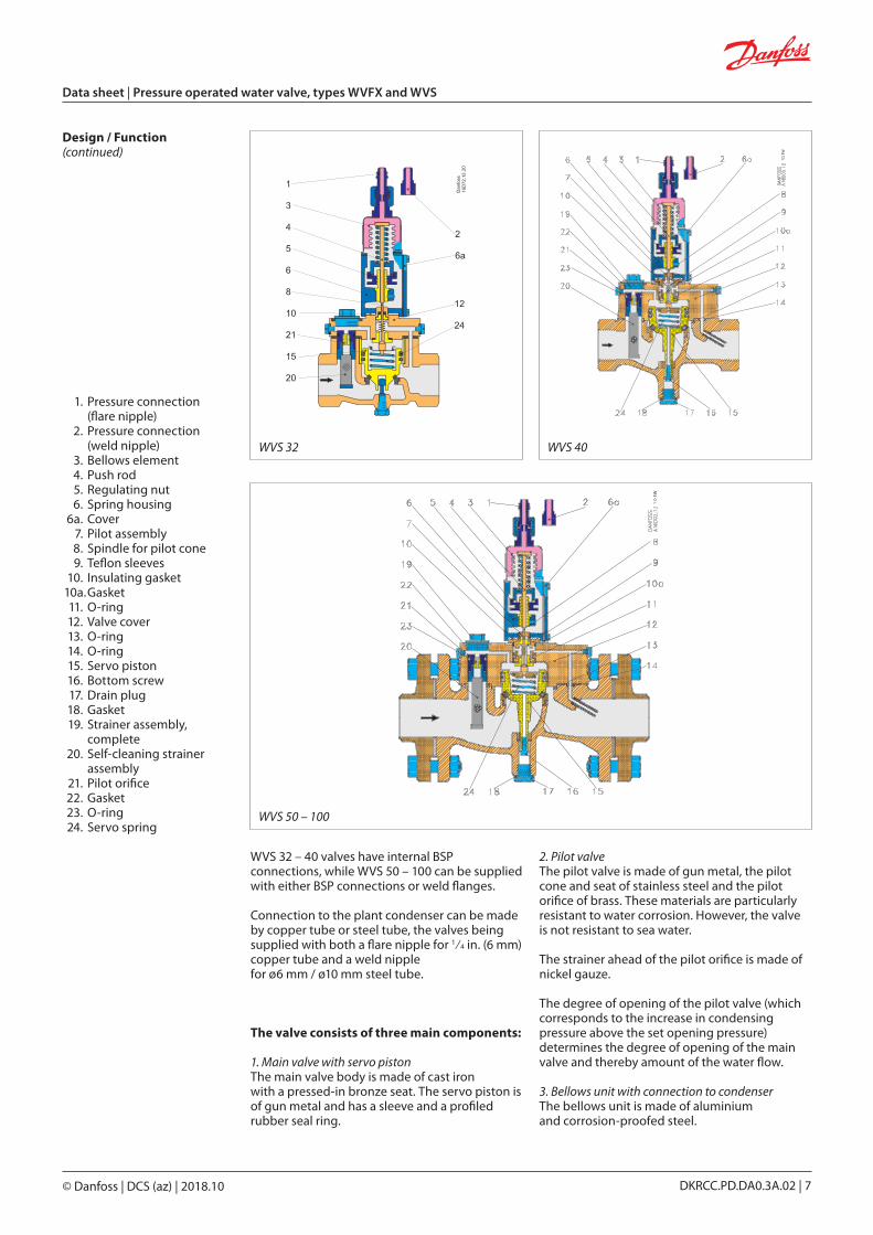
copy Danfoss | DCS (az) | 201810
WVS 32
WVS 50 ndash 100
WVS 40
Data sheet | Pressure operated water valve types WVFX and WVS
DKRCCPDDA03A02 | 7
Design Function (continued)
1 Pressure connection (flare nipple)
2 Pressure connection (weld nipple)
3 Bellows element 4 Push rod 5 Regulating nut 6 Spring housing 6a Cover 7 Pilot assembly 8 Spindle for pilot cone 9 Teflon sleeves 10 Insulating gasket 10a Gasket 11 O-ring 12 Valve cover 13 O-ring 14 O-ring 15 Servo piston 16 Bottom screw 17 Drain plug 18 Gasket 19 Strainer assembly
complete 20 Self-cleaning strainer
assembly 21 Pilot orifice 22 Gasket 23 O-ring 24 Servo spring
WVS 32 ndash 40 valves have internal BSP connections while WVS 50 ndash 100 can be supplied with either BSP connections or weld flanges
Connection to the plant condenser can be made by copper tube or steel tube the valves being supplied with both a flare nipple for 1frasl4 in (6 mm) copper tube and a weld nipple for oslash6 mm oslash10 mm steel tube
The valve consists of three main components
1 Main valve with servo piston The main valve body is made of cast iron with a pressed-in bronze seat The servo piston is of gun metal and has a sleeve and a profiled rubber seal ring
2 Pilot valve The pilot valve is made of gun metal the pilot cone and seat of stainless steel and the pilot orifice of brass These materials are particularly resistant to water corrosion However the valve is not resistant to sea water
The strainer ahead of the pilot orifice is made of nickel gauze
The degree of opening of the pilot valve (which corresponds to the increase in condensing pressure above the set opening pressure) determines the degree of opening of the main valve and thereby amount of the water flow
3 Bellows unit with connection to condenser The bellows unit is made of aluminium and corrosion-proofed steel
copy Danfoss | DCS (az) | 201810
Data sheet | Pressure operated water valve types WVFX and WVS
DKRCCPDDA03A02 | 8
Necessary mass flow
Volume flow
Sizing When sizing and selecting water regulating valves it is most important to ensure that the valve at any time is able to give the necessary quantity of cooling water
To select a suitable size of valve it is necessary to know the precise amount of cooling required
On the other hand to avoid the risk of unstable regulation (hunting) the valve should not be oversized
In general the aim should be to select the smallest valve capable of giving the required flow
To obtain a precise control it can be recommended to only use 85 of the capacity Below 85 the ratio between flow and condensing difference pressure is linear Above 85 the ratio is no longer linear To reach a 100 capacity the water valve needs significant increase of condensing pressure See fig below
Valve size
Sizing Examples Example 1 Condenser capacity Q0 30 kW Condensing temperature t0 35 degC Refrigerant R404A Cooling media water
Specific heat capacity of water Cp 419 kj(kgK) Water inlet temperature t1 15 degC Water outlet temperature t2 25 degC Pressure drop across valve ∆p max 10 bar
m = Q
c
3600 = 30
3600 = 2577 kgh C
p ∙ (t2 ndash t1) 419 ∙ (25 ndash 15)
∙
V = m
= 2577
asymp 26 m3h ρ 1000
∙ ∙
Type ∆p offset [bar]
WVFX 10 20
WVFX 15 25
WVFX 20 30
WVFX 25 35
WVFX 32 ndash 40 30
WVS 32 06
WVS 40 07
WVS 50 ndash 80 08
WVS 100 09
The following data is used when selecting the size of the water valve
y Cooling capacity of condenser y Temperature rise in cooling media y Differential pressure across valve
y Condensing temperature y Specific heat capacity of cooling media y Refrigerant
Water Capacity
Condensing pressure
Offset
copy Danfoss | DCS (az) | 201810
[bar]
[m3h]
Data sheet | Pressure operated water valve types WVFX and WVS
DKRCCPDDA03A02 | 9
Example 2 Condenser capacity QC 20 kW Condensing temperature tC 35 degC Refrigerant R134a Cooling media Brine Density of brine ρ 1015 kgm3
Specific heat capacity of water Cp 435 kj(kgK) Water inlet temperature t1 20 degC Water outlet temperature t2 25 degC Pressure drop across valve ∆p max 20 bar
Selecting size
Necessary mass flow
Volume flow
Kv value
V = m
= 3310
asymp 326 m3h ρ 1015
∙ ∙
m = Qc
3600 =
20 3600 = 3310 kgh
Cp ∙ (t2 ndash t1) 435 ∙ (25 ndash 20)
Kv ge V
= 326
= 232 m3h 1000 ∙ ∆p 1000 ∙ 20
ρ 1015
∙
Selecting size of WVFX 20 Kv ge 232 m3h =gt WVFX 20 WVFX 20 has Kv = 34 m3h and the necessary capacity is below 85 of full capacity
Code number The saturated pressure for R134a Tc = 35 degC Pc = 79 barg
Choose a WVFX 20 with 35 ndash 16 barg range
Selecting WVFX 20 Code number The saturated pressure for R404A Tc = 35 degC =gt Pc = 155 barg
Choose a WVFX 20 with 4 ndash 23 barg range
Standard servo spring type WVS
Special servo spring type WVS
copy Danfoss | DCS (az) | 201810
56
22
Oslash4
Oslash715
40
25
62
15
9
50
Dan
foss
3N20
011
Dan
foss
3-19
315
FW
Dan
foss
16D
031
4 FW
Dan
foss
3N15
731
0 FW
Dan
foss
16D
691
4 FW
WVFX 10 ndash 25
WVFX 32 ndash 40 WVS 32 ndash 40
WVS 50 ndash 100
Data sheet | Pressure operated water valve types WVFX and WVS
DKRCCPDDA03A02 | 10
Dimensions [mm] and weights [kg] Bracket for WVFX 10 ndash 25
copy Danfoss | DCS (az) | 201810 DKRCCPDDA03A02 | 11
Dimensions [mm] and weights [kg] (continued) Type H1 H2 H3 L L1 B oslash
Net weight
WVFX 10 91 133 ndash 72 11 ndash 55 10
WVFX 15 91 133 ndash 72 14 ndash 55 10
WVFX 20 91 133 ndash 90 16 ndash 55 20
WVFX 25 96 138 ndash 95 19 ndash 55 20
WVS 32 42 243 234 138 20 85 ndash 40
WVS 40 72 271 262 198 30 100 ndash 70
WVS 50 78 277 268 315 218 ndash 165 190
WVS 65 82 293 284 320 224 ndash 185 240
WVS 80 90 325 316 370 265 ndash 200 340
WVS 100 100 345 336 430 315 ndash 220 440
Type H1 H2 H3 L L1 B oslashNet
weight
WVS 32 42 259 250 138 20 85 ndash 40
WVS 40 72 287 278 198 30 100 ndash 70
WVS 50 78 293 2684 315 218 ndash 165 190
WVS 65 82 309 300 320 224 ndash 185 240
WVS 80 90 341 332 370 265 ndash 200 340
WVS 100 100 361 352 430 315 ndash 220 440
Pressure operated water valve type WVS - high pressure refrigerants
Pressure operated water valve
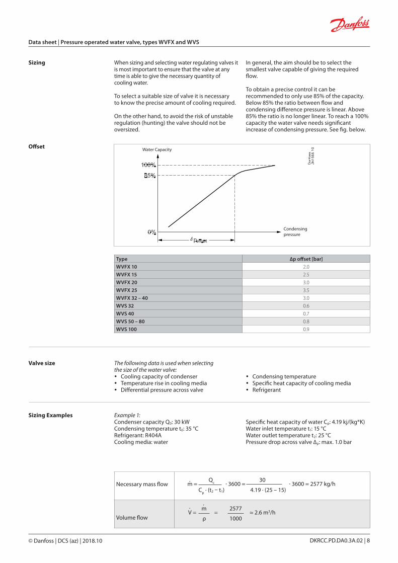
copy Danfoss | DCS (az) | 201810
Data sheet | Pressure operated water valve types WVFX and WVS
DKRCCPDDA03A02 | 8
Necessary mass flow
Volume flow
Sizing When sizing and selecting water regulating valves it is most important to ensure that the valve at any time is able to give the necessary quantity of cooling water
To select a suitable size of valve it is necessary to know the precise amount of cooling required
On the other hand to avoid the risk of unstable regulation (hunting) the valve should not be oversized
In general the aim should be to select the smallest valve capable of giving the required flow
To obtain a precise control it can be recommended to only use 85 of the capacity Below 85 the ratio between flow and condensing difference pressure is linear Above 85 the ratio is no longer linear To reach a 100 capacity the water valve needs significant increase of condensing pressure See fig below
Valve size
Sizing Examples Example 1 Condenser capacity Q0 30 kW Condensing temperature t0 35 degC Refrigerant R404A Cooling media water
Specific heat capacity of water Cp 419 kj(kgK) Water inlet temperature t1 15 degC Water outlet temperature t2 25 degC Pressure drop across valve ∆p max 10 bar
m = Q
c
3600 = 30
3600 = 2577 kgh C
p ∙ (t2 ndash t1) 419 ∙ (25 ndash 15)
∙
V = m
= 2577
asymp 26 m3h ρ 1000
∙ ∙
Type ∆p offset [bar]
WVFX 10 20
WVFX 15 25
WVFX 20 30
WVFX 25 35
WVFX 32 ndash 40 30
WVS 32 06
WVS 40 07
WVS 50 ndash 80 08
WVS 100 09
The following data is used when selecting the size of the water valve
y Cooling capacity of condenser y Temperature rise in cooling media y Differential pressure across valve
y Condensing temperature y Specific heat capacity of cooling media y Refrigerant
Water Capacity
Condensing pressure
Offset
copy Danfoss | DCS (az) | 201810
[bar]
[m3h]
Data sheet | Pressure operated water valve types WVFX and WVS
DKRCCPDDA03A02 | 9
Example 2 Condenser capacity QC 20 kW Condensing temperature tC 35 degC Refrigerant R134a Cooling media Brine Density of brine ρ 1015 kgm3
Specific heat capacity of water Cp 435 kj(kgK) Water inlet temperature t1 20 degC Water outlet temperature t2 25 degC Pressure drop across valve ∆p max 20 bar
Selecting size
Necessary mass flow
Volume flow
Kv value
V = m
= 3310
asymp 326 m3h ρ 1015
∙ ∙
m = Qc
3600 =
20 3600 = 3310 kgh
Cp ∙ (t2 ndash t1) 435 ∙ (25 ndash 20)
Kv ge V
= 326
= 232 m3h 1000 ∙ ∆p 1000 ∙ 20
ρ 1015
∙
Selecting size of WVFX 20 Kv ge 232 m3h =gt WVFX 20 WVFX 20 has Kv = 34 m3h and the necessary capacity is below 85 of full capacity
Code number The saturated pressure for R134a Tc = 35 degC Pc = 79 barg
Choose a WVFX 20 with 35 ndash 16 barg range
Selecting WVFX 20 Code number The saturated pressure for R404A Tc = 35 degC =gt Pc = 155 barg
Choose a WVFX 20 with 4 ndash 23 barg range
Standard servo spring type WVS
Special servo spring type WVS
copy Danfoss | DCS (az) | 201810
56
22
Oslash4
Oslash715
40
25
62
15
9
50
Dan
foss
3N20
011
Dan
foss
3-19
315
FW
Dan
foss
16D
031
4 FW
Dan
foss
3N15
731
0 FW
Dan
foss
16D
691
4 FW
WVFX 10 ndash 25
WVFX 32 ndash 40 WVS 32 ndash 40
WVS 50 ndash 100
Data sheet | Pressure operated water valve types WVFX and WVS
DKRCCPDDA03A02 | 10
Dimensions [mm] and weights [kg] Bracket for WVFX 10 ndash 25
copy Danfoss | DCS (az) | 201810 DKRCCPDDA03A02 | 11
Dimensions [mm] and weights [kg] (continued) Type H1 H2 H3 L L1 B oslash
Net weight
WVFX 10 91 133 ndash 72 11 ndash 55 10
WVFX 15 91 133 ndash 72 14 ndash 55 10
WVFX 20 91 133 ndash 90 16 ndash 55 20
WVFX 25 96 138 ndash 95 19 ndash 55 20
WVS 32 42 243 234 138 20 85 ndash 40
WVS 40 72 271 262 198 30 100 ndash 70
WVS 50 78 277 268 315 218 ndash 165 190
WVS 65 82 293 284 320 224 ndash 185 240
WVS 80 90 325 316 370 265 ndash 200 340
WVS 100 100 345 336 430 315 ndash 220 440
Type H1 H2 H3 L L1 B oslashNet
weight
WVS 32 42 259 250 138 20 85 ndash 40
WVS 40 72 287 278 198 30 100 ndash 70
WVS 50 78 293 2684 315 218 ndash 165 190
WVS 65 82 309 300 320 224 ndash 185 240
WVS 80 90 341 332 370 265 ndash 200 340
WVS 100 100 361 352 430 315 ndash 220 440
Pressure operated water valve type WVS - high pressure refrigerants
Pressure operated water valve
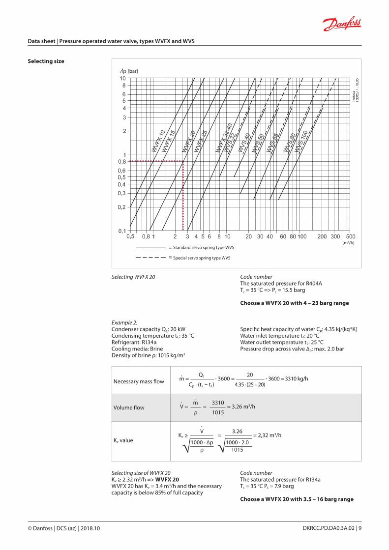
copy Danfoss | DCS (az) | 201810
[bar]
[m3h]
Data sheet | Pressure operated water valve types WVFX and WVS
DKRCCPDDA03A02 | 9
Example 2 Condenser capacity QC 20 kW Condensing temperature tC 35 degC Refrigerant R134a Cooling media Brine Density of brine ρ 1015 kgm3
Specific heat capacity of water Cp 435 kj(kgK) Water inlet temperature t1 20 degC Water outlet temperature t2 25 degC Pressure drop across valve ∆p max 20 bar
Selecting size
Necessary mass flow
Volume flow
Kv value
V = m
= 3310
asymp 326 m3h ρ 1015
∙ ∙
m = Qc
3600 =
20 3600 = 3310 kgh
Cp ∙ (t2 ndash t1) 435 ∙ (25 ndash 20)
Kv ge V
= 326
= 232 m3h 1000 ∙ ∆p 1000 ∙ 20
ρ 1015
∙
Selecting size of WVFX 20 Kv ge 232 m3h =gt WVFX 20 WVFX 20 has Kv = 34 m3h and the necessary capacity is below 85 of full capacity
Code number The saturated pressure for R134a Tc = 35 degC Pc = 79 barg
Choose a WVFX 20 with 35 ndash 16 barg range
Selecting WVFX 20 Code number The saturated pressure for R404A Tc = 35 degC =gt Pc = 155 barg
Choose a WVFX 20 with 4 ndash 23 barg range
Standard servo spring type WVS
Special servo spring type WVS
copy Danfoss | DCS (az) | 201810
56
22
Oslash4
Oslash715
40
25
62
15
9
50
Dan
foss
3N20
011
Dan
foss
3-19
315
FW
Dan
foss
16D
031
4 FW
Dan
foss
3N15
731
0 FW
Dan
foss
16D
691
4 FW
WVFX 10 ndash 25
WVFX 32 ndash 40 WVS 32 ndash 40
WVS 50 ndash 100
Data sheet | Pressure operated water valve types WVFX and WVS
DKRCCPDDA03A02 | 10
Dimensions [mm] and weights [kg] Bracket for WVFX 10 ndash 25
copy Danfoss | DCS (az) | 201810 DKRCCPDDA03A02 | 11
Dimensions [mm] and weights [kg] (continued) Type H1 H2 H3 L L1 B oslash
Net weight
WVFX 10 91 133 ndash 72 11 ndash 55 10
WVFX 15 91 133 ndash 72 14 ndash 55 10
WVFX 20 91 133 ndash 90 16 ndash 55 20
WVFX 25 96 138 ndash 95 19 ndash 55 20
WVS 32 42 243 234 138 20 85 ndash 40
WVS 40 72 271 262 198 30 100 ndash 70
WVS 50 78 277 268 315 218 ndash 165 190
WVS 65 82 293 284 320 224 ndash 185 240
WVS 80 90 325 316 370 265 ndash 200 340
WVS 100 100 345 336 430 315 ndash 220 440
Type H1 H2 H3 L L1 B oslashNet
weight
WVS 32 42 259 250 138 20 85 ndash 40
WVS 40 72 287 278 198 30 100 ndash 70
WVS 50 78 293 2684 315 218 ndash 165 190
WVS 65 82 309 300 320 224 ndash 185 240
WVS 80 90 341 332 370 265 ndash 200 340
WVS 100 100 361 352 430 315 ndash 220 440
Pressure operated water valve type WVS - high pressure refrigerants
Pressure operated water valve
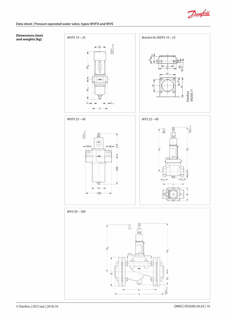
copy Danfoss | DCS (az) | 201810
56
22
Oslash4
Oslash715
40
25
62
15
9
50
Dan
foss
3N20
011
Dan
foss
3-19
315
FW
Dan
foss
16D
031
4 FW
Dan
foss
3N15
731
0 FW
Dan
foss
16D
691
4 FW
WVFX 10 ndash 25
WVFX 32 ndash 40 WVS 32 ndash 40
WVS 50 ndash 100
Data sheet | Pressure operated water valve types WVFX and WVS
DKRCCPDDA03A02 | 10
Dimensions [mm] and weights [kg] Bracket for WVFX 10 ndash 25
copy Danfoss | DCS (az) | 201810 DKRCCPDDA03A02 | 11
Dimensions [mm] and weights [kg] (continued) Type H1 H2 H3 L L1 B oslash
Net weight
WVFX 10 91 133 ndash 72 11 ndash 55 10
WVFX 15 91 133 ndash 72 14 ndash 55 10
WVFX 20 91 133 ndash 90 16 ndash 55 20
WVFX 25 96 138 ndash 95 19 ndash 55 20
WVS 32 42 243 234 138 20 85 ndash 40
WVS 40 72 271 262 198 30 100 ndash 70
WVS 50 78 277 268 315 218 ndash 165 190
WVS 65 82 293 284 320 224 ndash 185 240
WVS 80 90 325 316 370 265 ndash 200 340
WVS 100 100 345 336 430 315 ndash 220 440
Type H1 H2 H3 L L1 B oslashNet
weight
WVS 32 42 259 250 138 20 85 ndash 40
WVS 40 72 287 278 198 30 100 ndash 70
WVS 50 78 293 2684 315 218 ndash 165 190
WVS 65 82 309 300 320 224 ndash 185 240
WVS 80 90 341 332 370 265 ndash 200 340
WVS 100 100 361 352 430 315 ndash 220 440
Pressure operated water valve type WVS - high pressure refrigerants
Pressure operated water valve
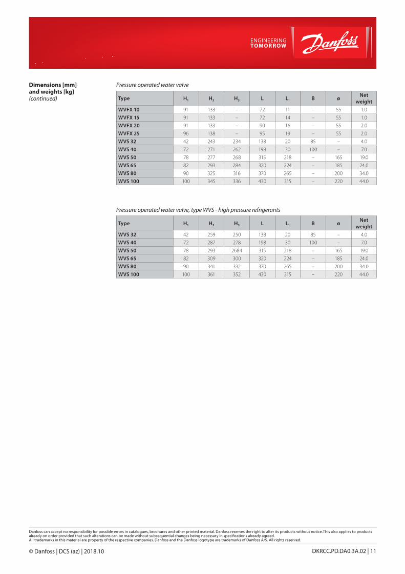