Embed Size (px)
Citation preview

Pressure IndependentControl Valves
The Future of Energy Saving
In modern Building Services projects,the desire for energy efficiency is aprimary consideration for designers,installers, manufacturers, and end users.HVAC systems offer an excellent opportunity for energysavings if the correct products are specified, selected andinstalled and the use of these products is clearly understood.
For installations incorporating fan coil units (FCU) or chilled beams, the Hattersley PICV offers an excellent solution for control of water flow rates, and therefore comfort control and energy savings when used as part of a variable volumesystem design.
For the installer, we offer a range of solutions which are easy to select, install and commission.
WHY CHOOSE THE HATTERSLEY FIG.1932 PICV?
Pressure IndependentControl Valves
Hattersley Pressure Independent Control Valves02
FAN COIL
DPCV
2 PORT FODRV
PICV
FAN COIL
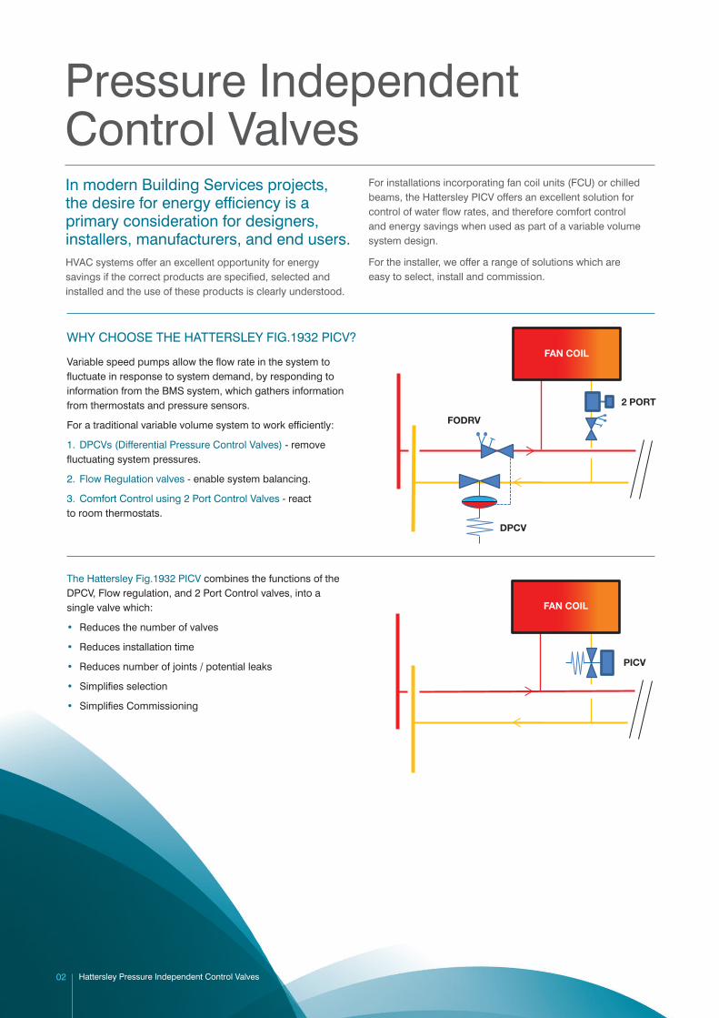
Variable speed pumps allow the flow rate in the system tofluctuate in response to system demand, by responding toinformation from the BMS system, which gathers informationfrom thermostats and pressure sensors.
For a traditional variable volume system to work efficiently:
1. DPCVs (Differential Pressure Control Valves) - removefluctuating system pressures.
2. Flow Regulation valves - enable system balancing.
3. Comfort Control using 2 Port Control Valves - reactto room thermostats.
The Hattersley Fig.1932 PICV combines the functions of theDPCV, Flow regulation, and 2 Port Control valves, into asingle valve which:
• Reduces the number of valves
• Reduces installation time
• Reduces number of joints / potential leaks
• Simplifies selection
• Simplifies Commissioning
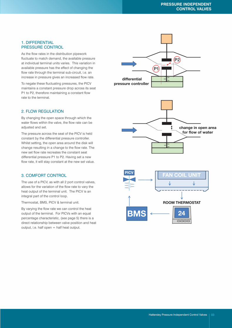
1. DIFFERENTIALPRESSURE CONTROL
As the flow rates in the distribution pipeworkfluctuate to match demand, the available pressureat individual terminal units varies. This variation inavailable pressure has the effect of changing theflow rate through the terminal sub-circuit, i.e. anincrease in pressure gives an increased flow rate.
To negate these fluctuating pressures, the PICVmaintains a constant pressure drop across its seatP1 to P2, therefore maintaining a constant flowrate to the terminal.
2. FLOW REGULATION
By changing the open space through which thewater flows within the valve, the flow rate can beadjusted and set.
The pressure across the seat of the PICV is heldconstant by the differential pressure controller.Whilst setting, the open area around the disk willchange resulting in a change to the flow rate. Thenew set flow rate recreates the constant seatdifferential pressure P1 to P2. Having set a newflow rate, it will stay constant at the new set value.
3. COMFORT CONTROL
The use of a PICV, as with all 2 port control valves,allows for the variation of the flow rate to vary theheat output of the terminal unit. The PICV is anintegral part of the control loop.
Thermostat, BMS, PICV & terminal unit.
By varying the flow rate we can control the heatoutput of the terminal. For PICVs with an equalpercentage characteristic, (see page 5) there is adirect relationship between valve position and heatoutput, i.e. half open = half heat output.
differentialpressure controller
P2
P1
BMS
FAN COIL UNIT
24
ROOM THERMOSTAT
PICV
change in open areafor flow of water
Hattersley Pressure Independent Control Valves 03
PRESSURE INDEPENDENTCONTROL VALVES
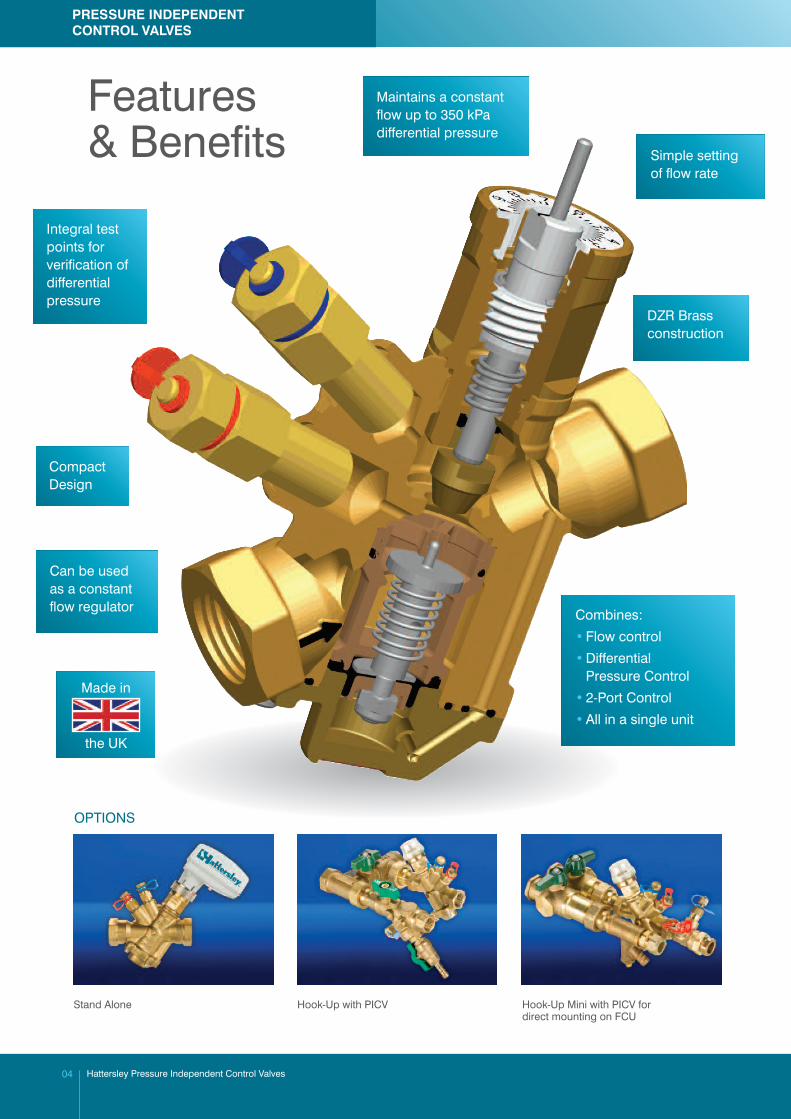
Features& Benefits
Integral testpoints forverification ofdifferentialpressure
Simple settingof flow rate
Maintains a constantflow up to 350 kPadifferential pressure
CompactDesign
DZR Brassconstruction
Can be usedas a constantflow regulator
OPTIONS
Stand Alone Hook-Up with PICV Hook-Up Mini with PICV fordirect mounting on FCU
Made in
the UK
Combines:
• Flow control
• Differential Pressure Control
• 2-Port Control
• All in a single unit
Hattersley Pressure Independent Control Valves04
PRESSURE INDEPENDENTCONTROL VALVES
EQUAL PERCENTAGE CHARACTERISTIC (= %)
The Hattersley Fig.1932 PICV / actuator combination, has an equal
percentage control characteristic at all pre-set flow rate positions
and under all part load conditions, maximising energy saving and
effective room temperature control.
The control characteristic of a PICV is the relationship between flow
rate and open position. When considering PICVs, the combined
PICV and matched actuator must be considered.
For terminal units using ‘forced air’, typically FCUs and active
chilled beams, an equal percentage control characteristic is
considered to be the best solution to maximise energy saving.
For the PICV to achieve good modulating control over the flow rate,
and subsequently the heat output from the terminal, the control
characteristic should be a ‘mirror image’ of the heat output
characteristic of the terminal unit. An equal percentage
characteristic does this.
The equal percentage characteristic establishes the relationship
between terminal unit heat output and valve open position, i.e. 50%
valve open position produces 50% heat output from the terminal,
whereas the flow rate may only be 30% of full design flow rate.
terminal output characteristic
PICV control characteristic
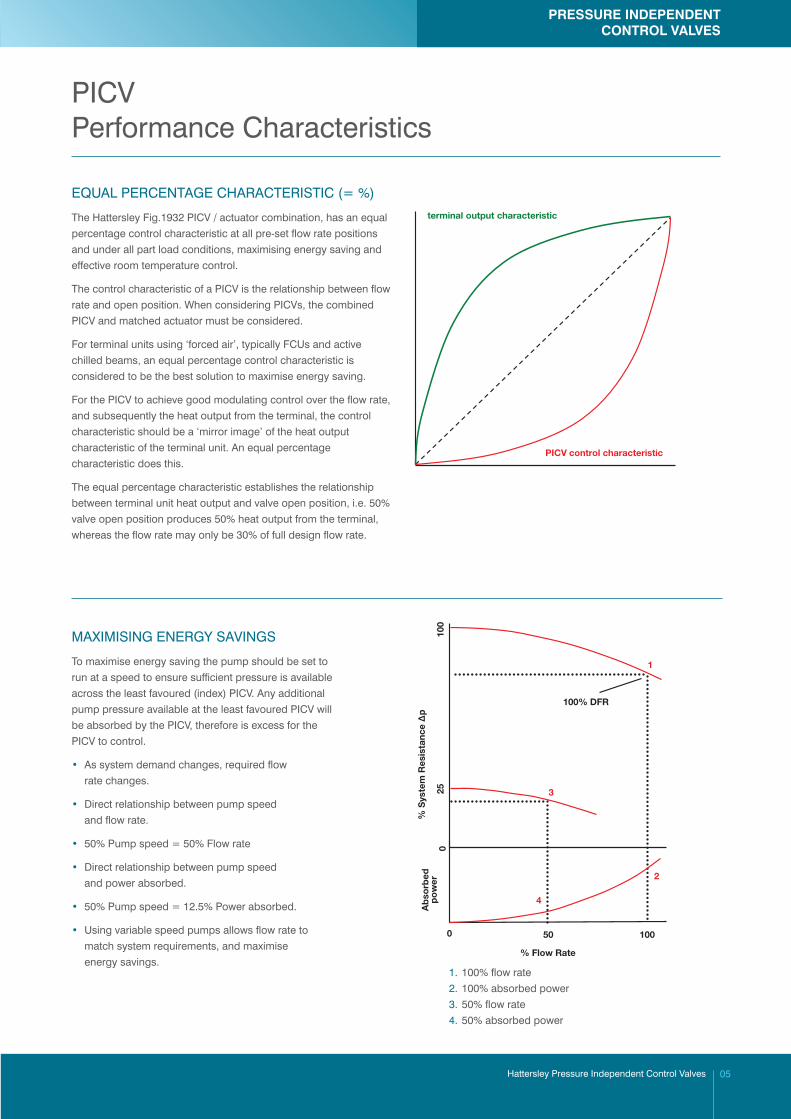
MAXIMISING ENERGY SAVINGS
To maximise energy saving the pump should be set to
run at a speed to ensure sufficient pressure is available
across the least favoured (index) PICV. Any additional
pump pressure available at the least favoured PICV will
be absorbed by the PICV, therefore is excess for the
PICV to control.
• As system demand changes, required flow
rate changes.
• Direct relationship between pump speed
and flow rate.
• 50% Pump speed = 50% Flow rate
• Direct relationship between pump speed
and power absorbed.
• 50% Pump speed = 12.5% Power absorbed.
• Using variable speed pumps allows flow rate to
match system requirements, and maximise
energy savings.
100% DFR
% S
yste
m R
esis
tanc
e Δp
% Flow Rate 0 50 100
25
100
A
bso
rbed
p
ow
er
0
1
3
4
2
1. 100% flow rate
2. 100% absorbed power
3. 50% flow rate
4. 50% absorbed power
PRESSURE INDEPENDENTCONTROL VALVES
Hattersley Pressure Independent Control Valves 05
PICVPerformance Characteristics
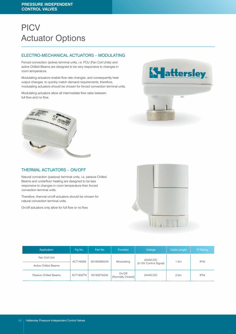
ELECTRO-MECHANICAL ACTUATORS – MODULATING
Forced convection (active) terminal units, i.e. FCU (Fan Coil Units) andactive Chilled Beams are designed to be very responsive to changes inroom temperature.
Modulating actuators enable flow rate changes, and consequently heatoutput changes, to quickly match demand requirements, therefore,modulating actuators should be chosen for forced convection terminal units.
Modulating actuators allow all intermediate flow rates betweenfull flow and no flow.
THERMAL ACTUATORS – ON/OFF
Natural convection (passive) terminal units, i.e. passive ChilledBeams and underfloor heating are designed to be lessresponsive to changes in room temperature than forcedconvection terminal units.
Therefore, thermal on/off actuators should be chosen fornatural convection terminal units.
On/off actuators only allow for full flow or no flow.
Application Fig No. Part No Function Voltage Cable Length IP Rating
Hattersley Pressure Independent Control Valves06
PICVActuator Options
Fan Coil UnitACT1932M 001932MA245 Modulating 24VAC/DC
(0-10V Control Signal) 1.5m IP43Active Chilled Beams
Passive Chilled Beams ACT1932TH 001932TA245 On/Off(Normally Closed) 24VAC/DC 2.0m IP54
PRESSURE INDEPENDENTCONTROL VALVES
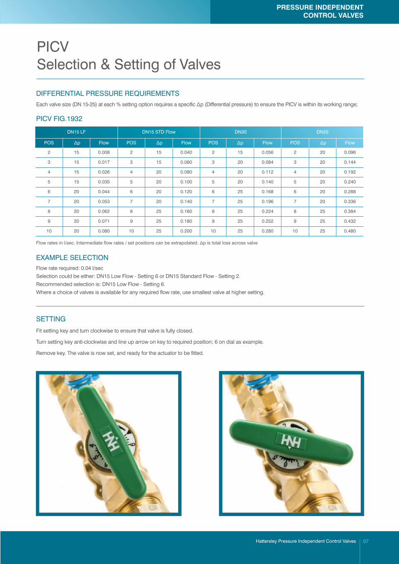
DIFFERENTIAL PRESSURE REQUIREMENTS
EXAMPLE SELECTIONFlow rate required: 0.04 l/sec
Selection could be either: DN15 Low Flow - Setting 6 or DN15 Standard Flow - Setting 2.
Recommended selection is: DN15 Low Flow - Setting 6.
Where a choice of valves is available for any required flow rate, use smallest valve at higher setting.
SETTING
Fit setting key and turn clockwise to ensure that valve is fully closed.
Turn setting key anti-clockwise and line up arrow on key to required position; 6 on dial as example.
Remove key. The valve is now set, and ready for the actuator to be fitted.
Each valve size (DN 15-25) at each % setting option requires a specific Δp (Differential pressure) to ensure the PICV is within its working range;
DN15 LF DN15 STD Flow DN20 DN25
POS �Δp Flow POS �Δp Flow POS Δp Flow POS �Δp Flow
PICV FIG.1932
Flow rates in l/sec. Intermediate flow rates / set positions can be extrapolated. Δp is total loss across valve
PRESSURE INDEPENDENTCONTROL VALVES
Hattersley Pressure Independent Control Valves 07
PICVSelection & Setting of Valves
2 15 0.008 2 15 0.040 2 15 0.056 2 20 0.096
3 15 0.017 3 15 0.060 3 20 0.084 3 20 0.144
4 15 0.026 4 20 0.080 4 20 0.112 4 20 0.192
5 15 0.035 5 20 0.100 5 20 0.140 5 20 0.240
6 20 0.044 6 20 0.120 6 25 0.168 6 20 0.288
7 20 0.053 7 20 0.140 7 25 0.196 7 20 0.336
8 20 0.062 8 25 0.160 8 25 0.224 8 25 0.384
9 20 0.071 9 25 0.180 9 25 0.252 9 25 0.432
10 20 0.080 10 25 0.200 10 25 0.280 10 25 0.480
Body DZR Brass BS EN 12165 (CW602N)
Bonnet DZR Brass BS EN 12165 (CW602N)
Bottom Cover DZR Brass BS EN 12165 (CW602N)
Test Points DZR Brass BS EN 12165 (CW602N)
Setting Key Nylon Grade PA 6
Cartridge PPS 40% GF
Diaphram EPDM
O Ring Seals EPDM
Springs Stainless Steel
SPECIFICATION: The PICV shall have a constant control characteristic at all flow settings and control flow rates at differential pressures up to 350 kPa. Flowrates will be externally adjustable, and set point recordable. Integral test points will be fitted to verify setting pressure allowing pumps to be set at optimumspeed to maximise energy savings. Shall be manufactured from DZR Brass, with Stainless Steel springs, and an EPDM diaphram. Shall be rated to PN16and operate at temperatures to 100°C. As Hattersley Fig.1932.
PRESSURE RATING: PN16 MEDIUM: Group 2 Liquids END CONNECTIONS: BSP Female to BS EN 10226
FEATURES & BENEFITS
• Maintains equal percentage control characteristic at all flow rate settings
• Pressure independent control of flow
• Simple flow rate setting
• Adjustable over wide range of flow rates
• Compact design
• Integral test points for Dp verification
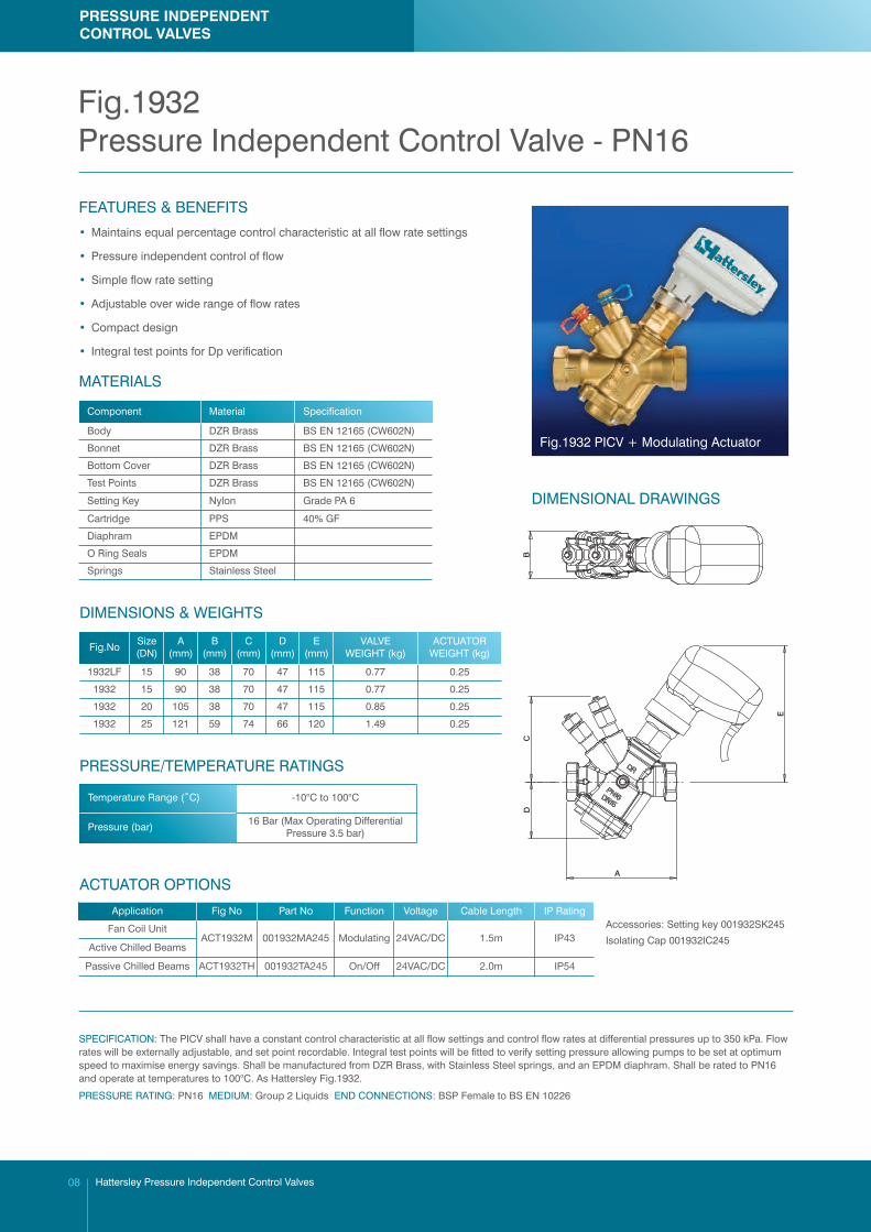
Fig.1932 PICV + Modulating Actuator
DIMENSIONAL DRAWINGS
MATERIALS
1932LF 15 90 38 70 47 115 0.77 0.25
1932 15 90 38 70 47 115 0.77 0.25
1932 20 105 38 70 47 115 0.85 0.25
1932 25 121 59 74 66 120 1.49 0.25
DIMENSIONS & WEIGHTS
Temperature Range (˚C) -10°C to 100°C
Pressure (bar) 16 Bar (Max Operating DifferentialPressure 3.5 bar)
PRESSURE/TEMPERATURE RATINGS
C
A
BD
E
Application Fig No Part No Function Voltage Cable Length IP Rating
ACTUATOR OPTIONS
Accessories: Setting key 001932SK245
Isolating Cap 001932IC245
Hattersley Pressure Independent Control Valves08
PRESSURE INDEPENDENTCONTROL VALVES
Fig.1932Pressure Independent Control Valve - PN16
Component Material Specification
Fig.NoSize(DN)
A(mm)
B(mm)
C(mm)
D(mm)
E(mm)
VALVEWEIGHT (kg)
ACTUATORWEIGHT (kg)
Fan Coil UnitACT1932M 001932MA245 Modulating 24VAC/DC 1.5m IP43
Active Chilled Beams
Passive Chilled Beams ACT1932TH 001932TA245 On/Off 24VAC/DC 2.0m IP54
PRESSURE RATING: PN16 MEDIUM: Group 2 Liquids END CONNECTIONS: BSP Female to BS EN 10226
SPECIFICATION: The PICV shall have a constant control characteristic at all flow settings and control flow rates at differential pressures up to 350 kPa. Flowrates will be externally adjustable, and set point recordable. Integral test points will be fitted to verify setting pressure allowing pumps to be set at optimumspeed to maximise energy savings. Shall be manufactured from DZR Brass, with Stainless Steel springs, and an EPDM diaphram. Shall be rated to PN16and operate at temperatures to 100°C. As Hattersley Fig.1932.
FEATURES & BENEFITS
• Maintains a constant flow rate
• Pressure independent control of flow
• Simple flow rate setting
• Adjustable over wide range of flow rates
• Compact design
• Integral test points for DP verification
DIMENSIONS & WEIGHTS
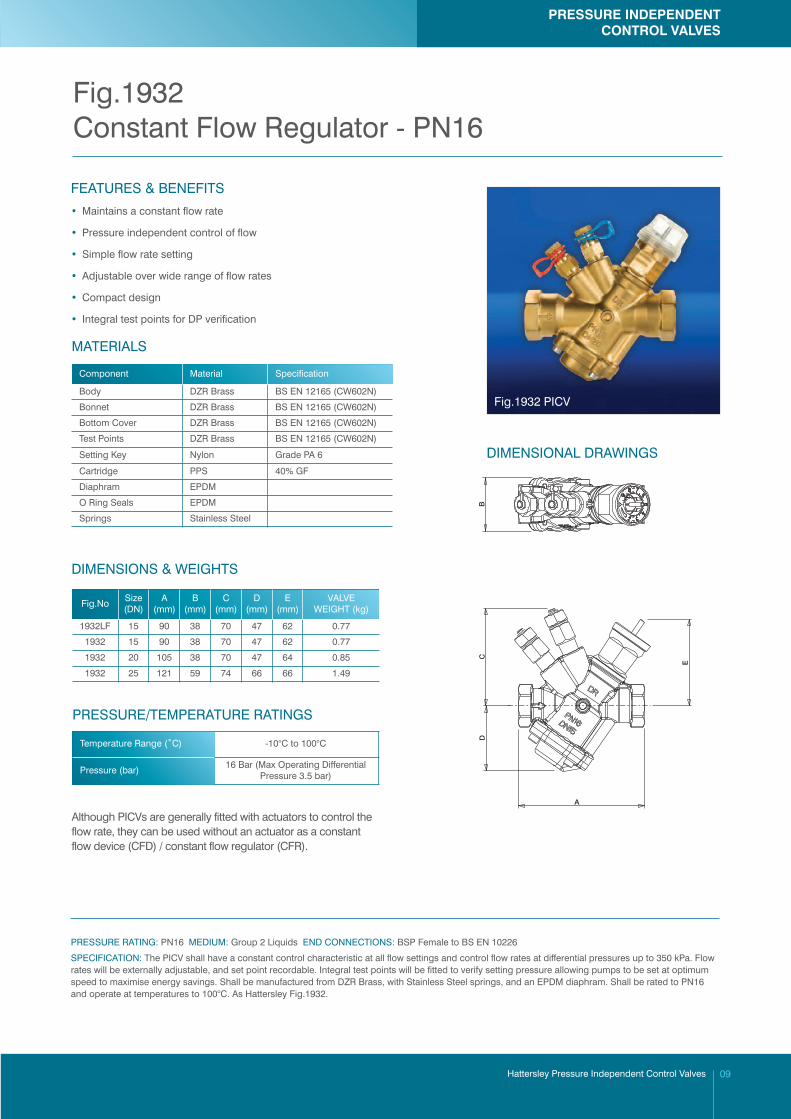
Although PICVs are generally fitted with actuators to control theflow rate, they can be used without an actuator as a constantflow device (CFD) / constant flow regulator (CFR).
DIMENSIONAL DRAWINGS
C
A
BD
E
PRESSURE INDEPENDENTCONTROL VALVES
Hattersley Pressure Independent Control Valves 09
Fig.1932Constant Flow Regulator - PN16
Fig.1932 PICV
Temperature Range (˚C) -10°C to 100°C
Pressure (bar) 16 Bar (Max Operating DifferentialPressure 3.5 bar)
PRESSURE/TEMPERATURE RATINGS
Body DZR Brass BS EN 12165 (CW602N)
Bonnet DZR Brass BS EN 12165 (CW602N)
Bottom Cover DZR Brass BS EN 12165 (CW602N)
Test Points DZR Brass BS EN 12165 (CW602N)
Setting Key Nylon Grade PA 6
Cartridge PPS 40% GF
Diaphram EPDM
O Ring Seals EPDM
Springs Stainless Steel
MATERIALS
Component Material Specification
1932LF 15 90 38 70 47 62 0.77
1932 15 90 38 70 47 62 0.77
1932 20 105 38 70 47 64 0.85
1932 25 121 59 74 66 66 1.49
Fig.NoSize(DN)
A(mm)
B(mm)
C(mm)
D(mm)
E(mm)
VALVEWEIGHT (kg)
The Hattersley Hook-Up is available in a wide range of standard variants, or can be manufacturedas a bespoke assembly to suit individual project requirements.
366P Series - including PICV without Flow Measurement Device.366PF Series - including PICV and Flow Measurement Device.
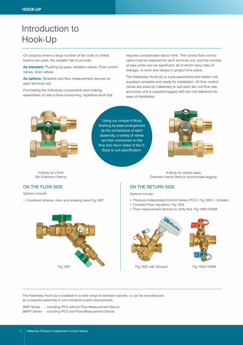
On projects where a large number of fan coils or chilledbeams are used, the installer has to provide:
As standard: Flushing by-pass, Isolation valves, Flow controlvalves, drain valves.
As options: Strainers and flow measurement devices oneach terminal unit.
Purchasing the individual components and makingassemblies on site is time-consuming, repetitive work that
requires considerable labour time. The correct flow controlvalve must be selected for each terminal unit, and the numberof pipe joints can be significant, all of which carry risks ofleakage, re-work and delays in project time plans.
The Hattersley Hook-Up is a pre-assembled and tested unitsupplied complete and ready for installation. All flow controlvalves are sized by Hattersley to suit each fan coil flow rate,and every unit is supplied tagged with fan coil reference forease of installation.
Using our unique H-Bodyflushing by-pass arrangement
as the cornerstone of eachassembly, a variety of valvesare then connected on the
flow and return sides of the H-Body to suit specification.
ON THE FLOW SIDEOptions include:
• Combined strainer, drain and isolating valve Fig.1807
ON THE RETURN SIDE
Options include:
• Pressure Independent Control Valves (PICV). Fig.1932 + Actuator• Constant Flow regulators. Fig.1932• Flow measurement devices to verify flow. Fig.1000/1000M
H-Body for LTHW(No Extension Stems)
H-Body for chilled water.Extension stems fitted to accomodate lagging.
Fig.1807 Fig.1932 with Actuator Fig.1000/1000M
HOOK-UP
Hattersley Pressure Independent Control Valves10
Introduction toHook-Up
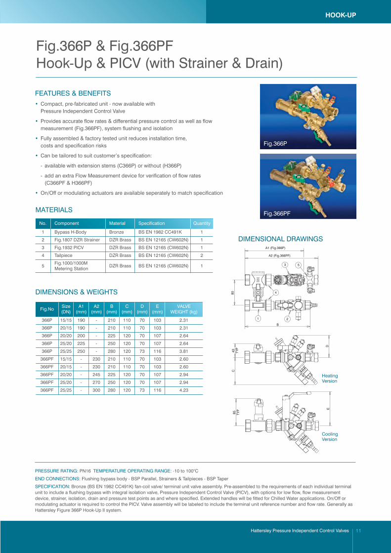
FEATURES & BENEFITS • Compact, pre-fabricated unit - now available with Pressure Independent Control Valve
• Provides accurate flow rates & differential pressure control as well as flow measurement (Fig.366PF), system flushing and isolation
• Fully assembled & factory tested unit reduces installation time, costs and specification risks
• Can be tailored to suit customer’s specification:
- available with extension stems (C366P) or without (H366P)
- add an extra Flow Measurement device for verification of flow rates (C366PF & H366PF)
• On/Off or modulating actuators are available seperately to match specification
DIMENSIONAL DRAWINGS
B
80TY
P43
TYP
85C
DE
1
4
2
3 5
A2 (Fig.366PF)
A1 (Fig.366P)
HeatingVersion
CoolingVersion
HOOK-UP
Hattersley Pressure Independent Control Valves 11
Fig.366P & Fig.366PFHook-Up & PICV (with Strainer & Drain)
1 Bypass H-Body Bronze BS EN 1982 CC491K 1
2 Fig.1807 DZR Strainer DZR Brass BS EN 12165 (CW602N) 1
3 Fig.1932 PICV DZR Brass BS EN 12165 (CW602N) 1
4 Tailpiece DZR Brass BS EN 12165 (CW602N) 2
5Fig.1000/1000MMetering Station
DZR Brass BS EN 12165 (CW602N) 1
MATERIALS
No. Component Material Specification Quantity
DIMENSIONS & WEIGHTS
366P 15/15 190 - 210 110 70 103 2.31
366P 20/15 190 - 210 110 70 103 2.31
366P 20/20 200 - 225 120 70 107 2.64
366P 25/20 225 - 250 120 70 107 2.64
366P 25/25 250 - 280 120 73 116 3.81
366PF 15/15 - 230 210 110 70 103 2.60
366PF 20/15 - 230 210 110 70 103 2.60
366PF 20/20 - 245 225 120 70 107 2.94
366PF 25/20 - 270 250 120 70 107 2.94
366PF 25/25 - 300 280 120 73 116 4.23
Fig.NoSize(DN)
A1(mm)
A2(mm)
B(mm)
C(mm)
D(mm)
E(mm)
VALVEWEIGHT (kg)
PRESSURE RATING: PN16 TEMPERATURE OPERATING RANGE: -10 to 100°C
END CONNECTIONS: Flushing bypass body - BSP Parallel, Strainers & Tailpieces - BSP Taper
SPECIFICATION: Bronze (BS EN 1982 CC491K) fan-coil valve/ terminal unit valve assembly. Pre-assembled to the requirements of each individual terminalunit to include a flushing bypass with integral isolation valve, Pressure Independent Control Valve (PICV), with options for low flow, flow measurementdevice, strainer, isolation, drain and pressure test points as and where specified. Extended handles will be fitted for Chilled Water applications. On/Off ormodulating actuator is required to control the PICV. Valve assembly will be labeled to include the terminal unit reference number and flow rate. Generally asHattersley Figure 366P Hook-Up II system.
Fig.366P
Fig.366PF
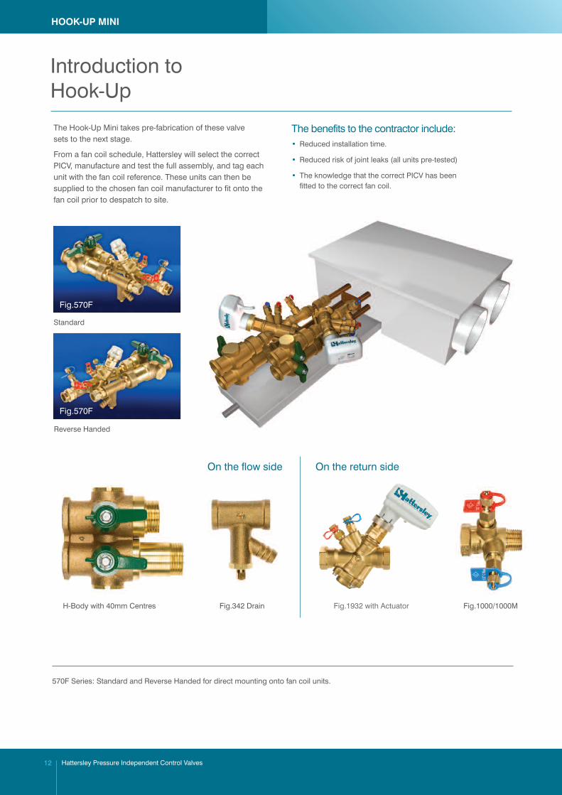
The Hook-Up Mini takes pre-fabrication of these valvesets to the next stage.
From a fan coil schedule, Hattersley will select the correctPICV, manufacture and test the full assembly, and tag eachunit with the fan coil reference. These units can then besupplied to the chosen fan coil manufacturer to fit onto thefan coil prior to despatch to site.
The benefits to the contractor include:• Reduced installation time.
• Reduced risk of joint leaks (all units pre-tested)
• The knowledge that the correct PICV has been fitted to the correct fan coil.
Fig.1932 with ActuatorFig.342 Drain Fig.1000/1000M
Standard
Reverse Handed
H-Body with 40mm Centres
On the flow side On the return side
HOOK-UP MINI
Hattersley Pressure Independent Control Valves12
Introduction toHook-Up
Fig.570F
Fig.570F
570F Series: Standard and Reverse Handed for direct mounting onto fan coil units.
A
40TY
P45
CD
37
B
7
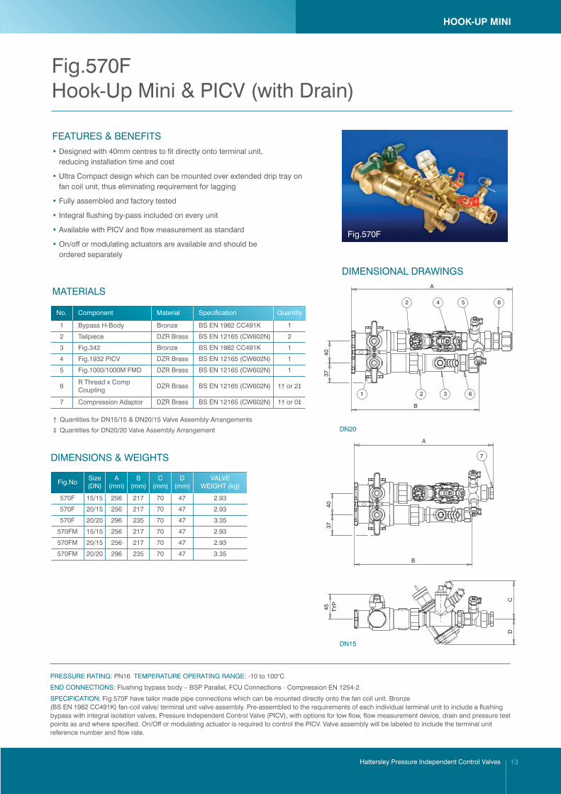
FEATURES & BENEFITS • Designed with 40mm centres to fit directly onto terminal unit,
reducing installation time and cost
• Ultra Compact design which can be mounted over extended drip tray onfan coil unit, thus eliminating requirement for lagging
• Fully assembled and factory tested
• Integral flushing by-pass included on every unit
• Available with PICV and flow measurement as standard
• On/off or modulating actuators are available and should beordered separately
MATERIALS
† Quantities for DN15/15 & DN20/15 Valve Assembly Arrangements
‡ Quantities for DN20/20 Valve Assembly Arrangement DN20
DN15
HOOK-UP MINI
Hattersley Pressure Independent Control Valves 13
Fig.570FHook-Up Mini & PICV (with Drain)
Fig.570F
1 Bypass H-Body Bronze BS EN 1982 CC491K 1
2 Tailpiece DZR Brass BS EN 12165 (CW602N) 2
3 Fig.342 Bronze BS EN 1982 CC491K 1
4 Fig.1932 PICV DZR Brass BS EN 12165 (CW602N) 1
5 Fig.1000/1000M FMD DZR Brass BS EN 12165 (CW602N) 1
6R Thread x CompCoupling
DZR Brass BS EN 12165 (CW602N) 1† or 2‡
7 Compression Adaptor DZR Brass BS EN 12165 (CW602N) 1† or 0‡
No. Component Material Specification Quantity
DIMENSIONS & WEIGHTS
570F 15/15 256 217 70 47 2.93
570F 20/15 256 217 70 47 2.93
570F 20/20 296 235 70 47 3.35
570FM 15/15 256 217 70 47 2.93
570FM 20/15 256 217 70 47 2.93
570FM 20/20 296 235 70 47 3.35
Fig.NoSize(DN)
A(mm)
B(mm)
C(mm)
D(mm)
VALVEWEIGHT (kg)
PRESSURE RATING: PN16 TEMPERATURE OPERATING RANGE: -10 to 100°C
END CONNECTIONS: Flushing bypass body – BSP Parallel, FCU Connections - Compression EN 1254-2
SPECIFICATION: Fig.570F have tailor made pipe connections which can be mounted directly onto the fan coil unit. Bronze(BS EN 1982 CC491K) fan-coil valve/ terminal unit valve assembly. Pre-assembled to the requirements of each individual terminal unit to include a flushingbypass with integral isolation valves, Pressure Independent Control Valve (PICV), with options for low flow, flow measurement device, drain and pressure testpoints as and where specified. On/Off or modulating actuator is required to control the PICV. Valve assembly will be labeled to include the terminal unitreference number and flow rate.
DIMENSIONAL DRAWINGS
4037
A
B
1 2
2
3
4 65
6

01. Q. Can I measure flow rate?
A. No. Flow rate cannot be measured directly from the PICV. Other means of flow verification such as orifice plates/ flow measurement devices should be installed as part of the system. However, the flow rate can be established from valve set position, and our published chart on Page 7.
02. Q. What are the test points used for?
A. They are used to verify the pressure drop across the seat to check that the valve is operating at the correct pressure drop. Please refer to the IOM.
03. Q. How do I know if the PICV is working correctly?
A. This can be verified by measuring the pressure drop across the seat using the test points and then comparing against the detail provided in FAQ 2.
04. Q. Can I install the PICV upside down?
A. The PICV can be mounted in any orientation. However consideration needs to be given to choice of actuator. Thermal actuators can be installed in any orientation, but Electro-Mechanical actuators should not be installed upside down as this can allow moisture to enter the actuator. However, a PICV with an electro-mechanical actuator can be orientated anywhere between 0-90 ̊ from the vertical.
05. Q. Can I install the PICV on flow or return?
A. The PICV can be installed on either flow and return. Please ensure that the valve is installed with the flow direction arrow in the correct direction.
06. Q. Does it matter which way around the PICV is installed?
A. The PICV must be installed with the flow direction arrow in the correct direction.
07. Q. How accurate is the pre-setting?
A. With careful alignment of the setting dial to desired flow rate position, a pre-set accuracy of +/- 10% can be achieved.
08. Q. Can I flush through the PICV?
A. It is not recommended to flush through PICVs. The PICV is a control valve with close tolerance flow paths. Flushing through these valves may introduce debris which could block the flow paths.
09. Q. Are the valves able to isolate?
A. Control valves are not designed to be isolating valves, and it is always recommended to fit separate isolating valves. However for routine maintenance purposes, i.e. strainer cleaning, the actuator can be removed, and a manual cap fitted which can be used to close the valve.
10. Q. How do I commission using PICVs?
A. BSRIA Guide to Commissioning Water Systems BG2 / 2010 and CIBSE Commissioning Code W: 2010 give details of commissioning procedures using PICVs.
Hattersley Pressure Independent Control Valves14
PRESSURE INDEPENDENTCONTROL VALVES
PICVFrequently Asked Questions


PO BOX 719, IPSWICH, IP1 9UD
HOME SALES: +44 (0)1744 458670EXPORT SALES: +44 (0)1744 458671FAX: +44 (0)1744 26912EMAIL: [email protected]: [email protected]
www.hattersley .com H_P
ICV_0213_v2
• Designed and manufactured under quality management systems in accordance with BS EN 9001:2008
Visit www.flowoffluids.com to order yourcopy of the New Technical Paper 410.
FM311ISO 9001
Every effort has been made to ensure that the information contained in this publication is accurate at the time of
publishing. Hattersley assumes no responsibility or liability for typographical errors or omissions or for any
misinterpretation of the information within this publication and reserves the right to change without notice.
We hope that our communications have an impact on you, but not on the environment. We have taken steps toensure this leaflet is printed on FSC material and the paper is made by a totally chlorine free process.
www.flowoffluids.com
F U T U R E V A L V E T E C H N O L O G Y
To visit ourVideo Library
go to:
www.youtube.com/user/hattersleyvalves
www.cranebsu.com