Embed Size (px)
Citation preview
© RENAULT 2005 Origin: PEGI - Renault Page : 1 / 52
Press tooling. Blank cutting tool. Basics on design
GE24-051R /A ________________________________________
Guide ________________________________________
Status Enforceable Importante Note : This document has been translated from the french. In the event of any dispute, only th french
version is referred to as the reference text and is binding on the parties. Object Define the recommendations for the design of blank cutting tools. Scope of application Renault group Issued by 65307 - Stamping Process Industrialisation Confidentiality Non confidential
Approved by Function Signature Application date
D. Couratin Head of 65307 Department 03/2005
GE24-051R /A
© RENAULT 2005 Origin: PEGI - Renault Page : 2 / 52
History of versions
Version Update Object of main modifications Author A 03/2005 Creation J Lebars (1)
Supersedes Availability Inside Renault, on the Intranet: http://gdxpegi.ava.tcr.renault.fr
Outside Renault, on the Internet: www.cnomo.com E.mail : [email protected]
Documents cited Regulations : International : European : French : CNOMO : Renault : EM24.02.030, EM24.02.031, EM24.02.033, EM24.03.200,
EM24.03.400, EM24.15.100, EM24.54.300, EM24.54.500, EM24.55.100, EM24.57.500, EM24.59.150, EM24.59.150, GE24-014R, GE24-015R, GE24-050R.
Other internal doc : Other external doc : Coding ICS : 25.120.10 ; 03.120.20 Class E24 Key words Emboutissage, outillage de presse, fondamentaux, outil de découpe flans, équipement de
presse, stamping, pressing, press tooling, basics, tool fan blank cutting, press equipment Language English (1) Have participated in writing the document Site Dept Name Site Dept Name Sandouville
9610 LECHEVALIER
Douai 9910 PAOLIERI Flins 9410 ZERDAG Maubeuge MCA GRASSART Valladolid 954 DEL-CANO Valladolid 644 SAIZ Valladolid 611 SEBASTIAN
GE24-051R /A
© RENAULT 2005 Origin: PEGI - Renault Page : 3 / 52
Contents Page
Foreword ...................................................................................................................................4
1 General on tooling ....................................................................................................................5 1.1 Height of the cutting plane in respect of feed plane................................................................................... 5 1.2 Specific and standard tool frames.............................................................................................................. 5 1.3 Cutting elements (material) ........................................................................................................................ 6 1.4 Blade design............................................................................................................................................... 6 1.5 Blade outputs ........................................................................................................................................... 10 1.6 Cutting rework .......................................................................................................................................... 11 1.7 Belt lifter.................................................................................................................................................... 11 1.8 Belt guide.................................................................................................................................................. 11 1.9 Stripper ..................................................................................................................................................... 11 1.10 Notching specific belt holder .................................................................................................................... 15 1.11 Belt guide «Particular cases » .................................................................................................................... 16 1.12 Evacuation of non recovered scrap.......................................................................................................... 16
2 Fitting under PAL � PAC press .............................................................................................17 2.1 Conditions of evacuation of blanks and scraps........................................................................................ 17 2.2 Frames ..................................................................................................................................................... 18 2.3 Standardising of connections ................................................................................................................... 18 2.4 Specific tooling ......................................................................................................................................... 20 2.5 Lateral evacuation moving frame ............................................................................................................. 24 2.6 Tooling fitted on the riser size 500 (with plant approval).......................................................................... 26 2.7 Standard frames with fixed shear............................................................................................................. 26 2.8 Standard frames with moving shear......................................................................................................... 26 2.9 Specific equipment ................................................................................................................................... 27 2.10 Standard frame with 2 moving shears...................................................................................................... 29 2.11 Fitting schedule � Backup all plants......................................................................................................... 29 2.12 Press not fitted with a magnetic belt ........................................................................................................ 29 2.13 Double HOF ............................................................................................................................................. 32 2.14 Cutting on floating blade........................................................................................................................... 33 2.15 Tool fitting by push rod ............................................................................................................................. 34
3 Fitting under PAVAR press....................................................................................................35 3.1 Conditions of evacuation of blanks and scraps........................................................................................ 35 3.2 Frame ....................................................................................................................................................... 35 3.3 Standardising of connections ................................................................................................................... 35 3.4 Specific tooling ......................................................................................................................................... 36 3.5 Lateral evacuation .................................................................................................................................... 38 3.6 Tooling fitted on the riser size 500 mm (with plant approval) .................................................................. 39 3.7 Standard frames with HOF shear: 630 and 1130 ± 1 .............................................................................. 39
4 Fitting under press 4000 kN X 2 (2.5)....................................................................................40 4.1 Specific 1-blank tooling ............................................................................................................................ 40 4.2 Specific 2-blank tooling ............................................................................................................................ 40 4.3 Standard frames with fixed shear............................................................................................................. 40 4.4 Standard frames with 1 moving shear...................................................................................................... 40

GE24-051R /A
© RENAULT 2005 Origin: PEGI - Renault Page : 4 / 52
4.5 Conditions of evacuation of blanks and scraps........................................................................................ 40 4.6 Connections ............................................................................................................................................. 40 4.7 Cutting elements ...................................................................................................................................... 40 4.8 Stripper ..................................................................................................................................................... 40 4.9 Belt guiding............................................................................................................................................... 40 4.10 Belt lifter.................................................................................................................................................... 40 4.11 Belt advance check .................................................................................................................................. 40
5 Fitting under press 2500 or 4000 kN x 1.6 ............................................................................41 5.1 Tooling specific to a part .......................................................................................................................... 41 5.2 Standard frames with fixed shear............................................................................................................. 41 5.3 Standardised frames with 1 moving shear............................................................................................... 41 5.4 Conditions of evacuation of blanks and scraps........................................................................................ 41 5.5 Standardising of connections ................................................................................................................... 41 5.6 Cutting elements ...................................................................................................................................... 42 5.7 Stripper ..................................................................................................................................................... 42 5.8 Belt guiding............................................................................................................................................... 42 5.9 Belt lifter.................................................................................................................................................... 42 5.10 Blank evacuation ...................................................................................................................................... 42
6 List of frames and standard shears available in plants ......................................................44 6.1 Workshop 32 - Douai - UGB .................................................................................................................... 44 6.2 Workshop Flins � UPL............................................................................................................................. 46 6.3 Workshop 47- Sandouville - LHA............................................................................................................. 47 6.4 Workshop Maubeuge - MCA.................................................................................................................... 48 6.5 Workshop 230 - Palencia ......................................................................................................................... 49 6.6 Workshop 644 - Valladolid ....................................................................................................................... 50 6.7 Workshop 650 � Valladolid ...................................................................................................................... 51
7 List of documents cited .........................................................................................................52
Foreword This guide is not:
A collection of « design rules ». Exhaustive in propositions.
This guide is a reminder of a few basics and examples, and must be enriched with: The different user projects. All manufacturing sites by the intermediate of different DIVDs.
NOTE: Cutting for butt welding This guide can be used for tools for cutting blanks for butt welding, but in case of contradiction, use preferably guide GE24-050R.
GE24-051R /A
© RENAULT 2005 Origin: PEGI - Renault Page : 5 / 52
1 General on tooling
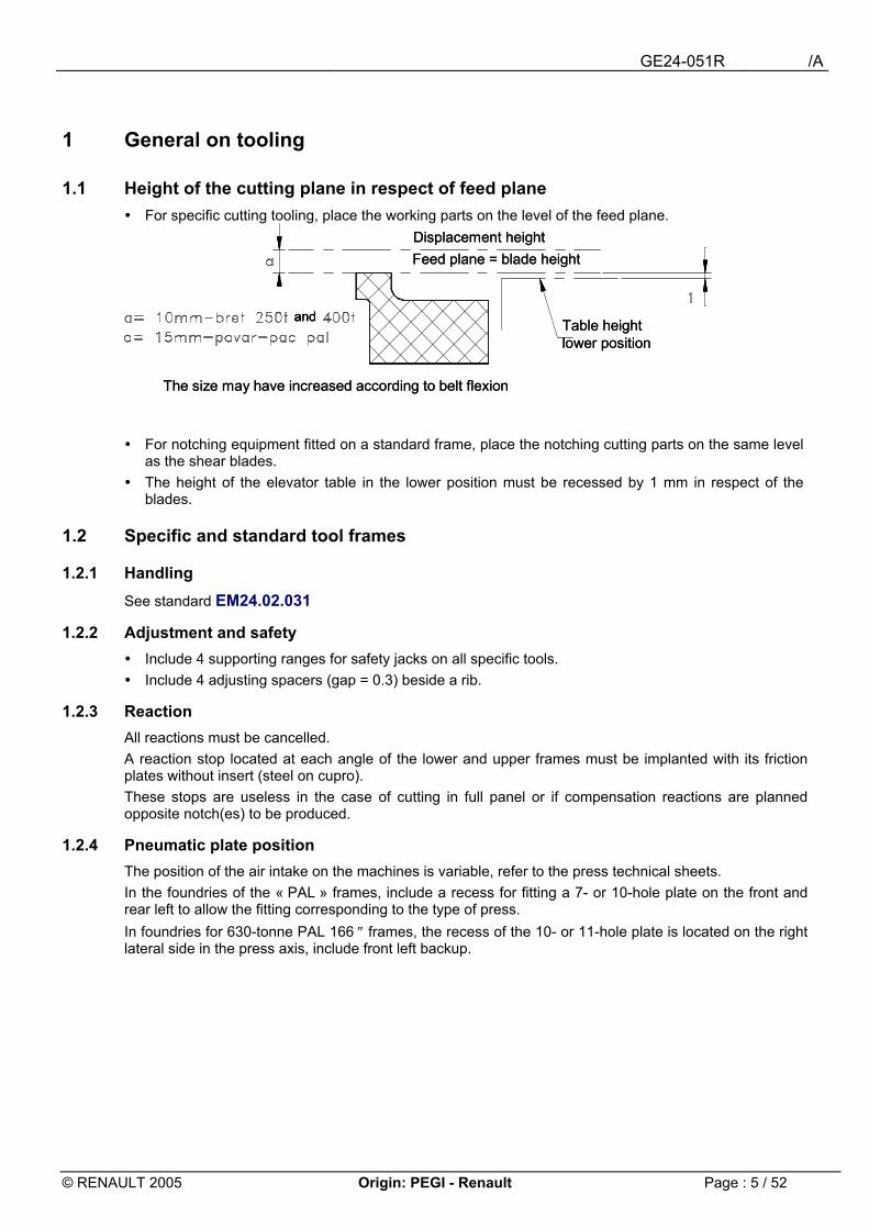
1.1 Height of the cutting plane in respect of feed plane ! For specific cutting tooling, place the working parts on the level of the feed plane.
! For notching equipment fitted on a standard frame, place the notching cutting parts on the same level
as the shear blades. ! The height of the elevator table in the lower position must be recessed by 1 mm in respect of the
blades.
1.2 Specific and standard tool frames
1.2.1 Handling See standard EM24.02.031
1.2.2 Adjustment and safety ! Include 4 supporting ranges for safety jacks on all specific tools. ! Include 4 adjusting spacers (gap = 0.3) beside a rib.
1.2.3 Reaction All reactions must be cancelled. A reaction stop located at each angle of the lower and upper frames must be implanted with its friction plates without insert (steel on cupro). These stops are useless in the case of cutting in full panel or if compensation reactions are planned opposite notch(es) to be produced.
1.2.4 Pneumatic plate position The position of the air intake on the machines is variable, refer to the press technical sheets. In the foundries of the « PAL » frames, include a recess for fitting a 7- or 10-hole plate on the front and rear left to allow the fitting corresponding to the type of press. In foundries for 630-tonne PAL 166 ″ frames, the recess of the 10- or 11-hole plate is located on the right lateral side in the press axis, include front left backup.
and
The size may have increased according to belt flexion
Displacement heightFeed plane = blade height
Table height lower position
andand
The size may have increased according to belt flexion
Displacement heightFeed plane = blade height
Table height lower position
GE24-051R /A
© RENAULT 2005 Origin: PEGI - Renault Page : 6 / 52
1.3 Cutting elements (material)
Operation Panel thickness < 1 mm Panel thickness ≤ 1 mm NOTCHING
X153CrMoV12-T6 (56-58 HRC) or GE 280 refilled
X153CrMoV12-T6 (56-58 HRC)
CUTTING OUT X153CrMoV12-T6 (56-58 HRC) or GE 280 refilled
X153CrMoV12-T6 (56-58 HRC)
BLADES STRAIGHT
X153CrMoV12-T6 (56-58 HRC) 42CrMo4 refilled (2 edges)
X153CrMoV12-T6 (56-58 HRC)
BLADES CURVED
X153CrMoV12-T6 (56-58 HRC) 42CrMo4 refilled (2 edges)
X153CrMoV12-T6 (56-58 HRC)
Note: Refilling see standard EM24.15.100.
Do not use refilled blades for skin parts or panel > 220 Mpa
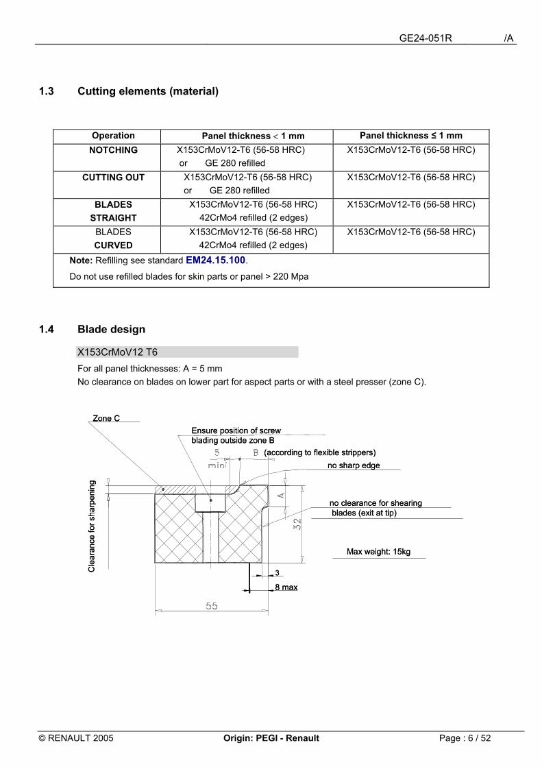
1.4 Blade design
X153CrMoV12 T6 For all panel thicknesses: A = 5 mm No clearance on blades on lower part for aspect parts or with a steel presser (zone C).
Zone C
3
8 max
Cle
aran
ce fo
r sha
rpen
ing
Ensure position of screw blading outside zone B
Max weight: 15kg
no sharp edge(according to flexible strippers)
no clearance for shearingblades (exit at tip)
Zone C
3
8 max
Cle
aran
ce fo
r sha
rpen
ing
Ensure position of screw blading outside zone B
Max weight: 15kg
no sharp edge(according to flexible strippers)
no clearance for shearingblades (exit at tip)
GE24-051R /A
© RENAULT 2005 Origin: PEGI - Renault Page : 7 / 52
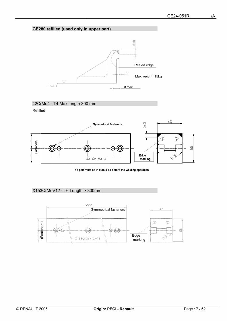
GE280 refilled (used only in upper part)
42CrMo4 - T4 Max length 300 mm Refilled
X153CrMoV12 - T6 Length > 300mm
8 maxi
Max weight: 15kg
Refiled edge
The part must be in status T4 before the welding operation
(Fas
tene
rs)
Symmetrical fasteners
Edgemarking
The part must be in status T4 before the welding operation
(Fas
tene
rs)
Symmetrical fasteners
Edgemarking
>
(Fas
tene
rs)
Symmetrical fasteners
Edgemarking
GE24-051R /A
© RENAULT 2005 Origin: PEGI - Renault Page : 8 / 52
1.4.1 Cutting sets See standard EM24.02.030
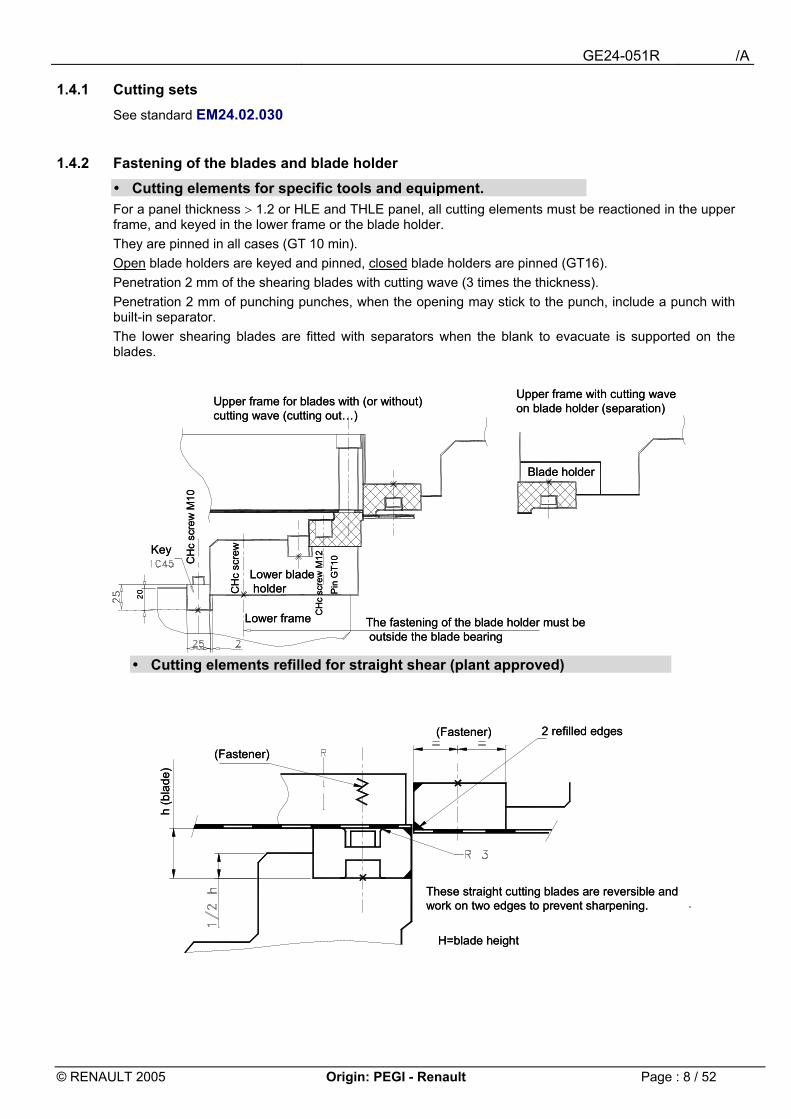
1.4.2 Fastening of the blades and blade holder ! Cutting elements for specific tools and equipment. For a panel thickness > 1.2 or HLE and THLE panel, all cutting elements must be reactioned in the upper frame, and keyed in the lower frame or the blade holder. They are pinned in all cases (GT 10 min). Open blade holders are keyed and pinned, closed blade holders are pinned (GT16). Penetration 2 mm of the shearing blades with cutting wave (3 times the thickness). Penetration 2 mm of punching punches, when the opening may stick to the punch, include a punch with built-in separator. The lower shearing blades are fitted with separators when the blank to evacuate is supported on the blades.
! Cutting elements refilled for straight shear (plant approved)
20
Upper frame for blades with (or without) cutting wave (cutting out�)
Upper frame with cutting waveon blade holder (separation)
Lower bladeholder
Key
CH
csc
rew
M10
Blade holder
The fastening of the blade holder must beoutside the blade bearing
Lower frame
Pin
GT1
0C
Hc
scre
wM
12
CH
csc
rew
20
Upper frame for blades with (or without) cutting wave (cutting out�)
Upper frame with cutting waveon blade holder (separation)
Lower bladeholder
Key
CH
csc
rew
M10
Blade holder
The fastening of the blade holder must beoutside the blade bearing
Lower frame
Pin
GT1
0C
Hc
scre
wM
12
CH
csc
rew
H=blade height
These straight cutting blades are reversible and work on two edges to prevent sharpening.
h (b
lade
)
(Fastener)
(Fastener) 2 refilled edges
H=blade height
These straight cutting blades are reversible and work on two edges to prevent sharpening.
h (b
lade
)
(Fastener)
(Fastener) 2 refilled edges
GE24-051R /A
© RENAULT 2005 Origin: PEGI - Renault Page : 9 / 52
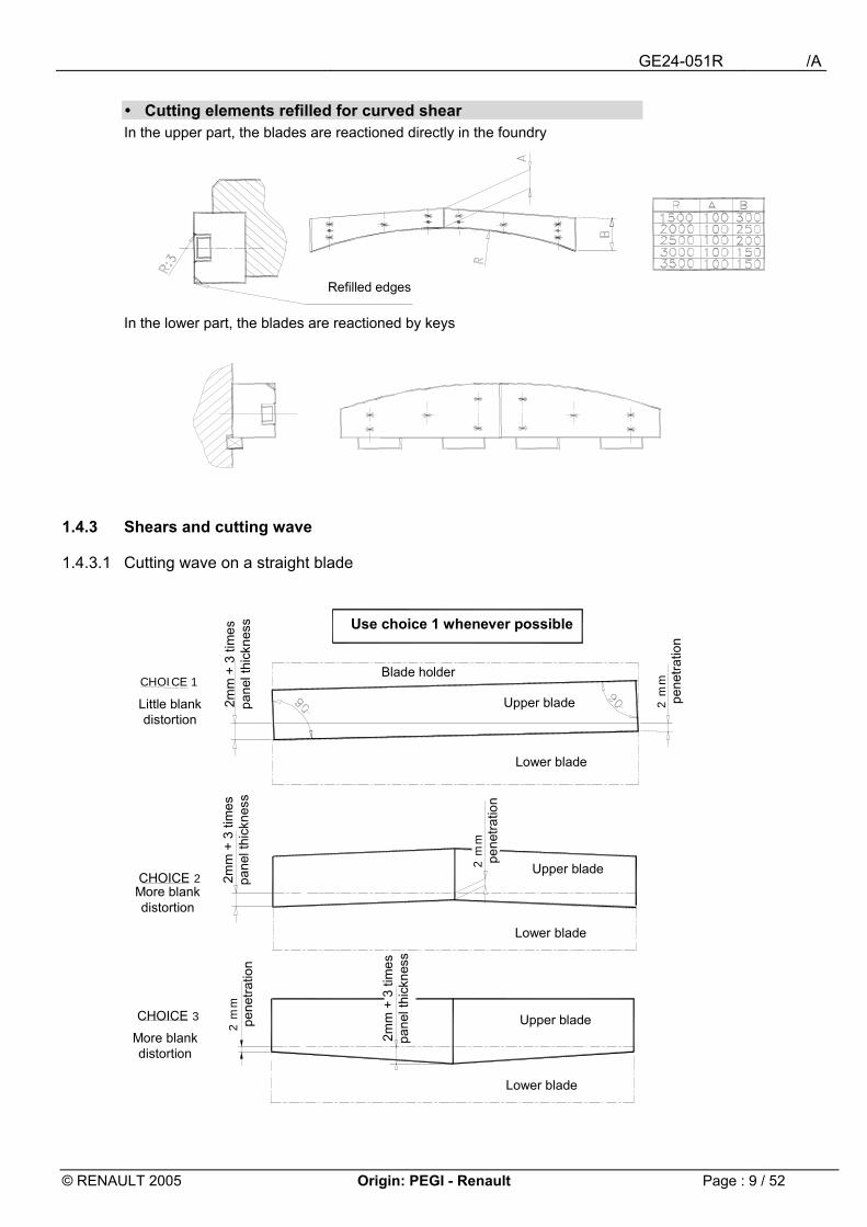
! Cutting elements refilled for curved shear In the upper part, the blades are reactioned directly in the foundry
In the lower part, the blades are reactioned by keys
1.4.3 Shears and cutting wave
1.4.3.1 Cutting wave on a straight blade
Refilled edges
Lower blade
2 m
mpe
netra
tion
CHOICE 3
Lower blade
Lower blade
Upper blade
Upper blade
Upper blade
Use choice 1 whenever possible
Blade holder
CHOICE 2More blankdistortion
CHOICE 1
Little blank distortion
2mm
+ 3
tim
es
pane
l thi
ckne
ss2m
m +
3 ti
mes
pa
nel t
hick
ness
2mm
+ 3
tim
es
pane
l thi
ckne
ss
2 m
mpe
netra
tion
2 m
mpe
netra
tion
More blankdistortion
GE24-051R /A
© RENAULT 2005 Origin: PEGI - Renault Page : 10 / 52
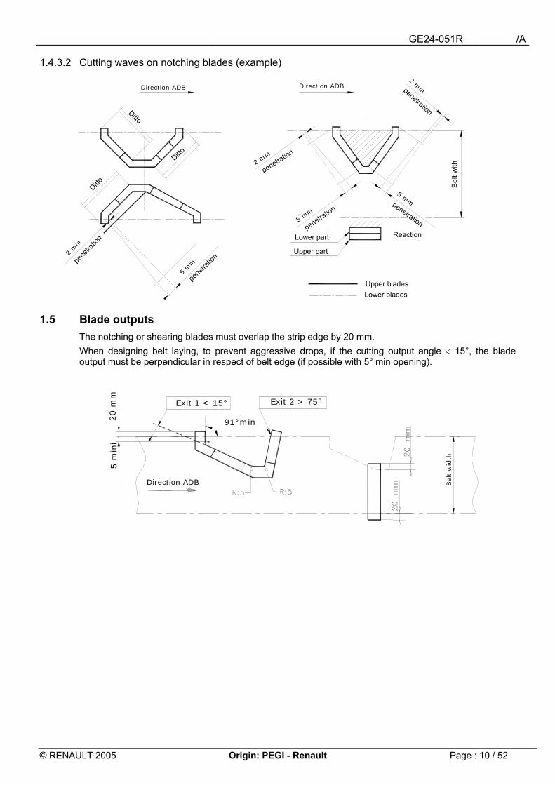
1.4.3.2 Cutting waves on notching blades (example)
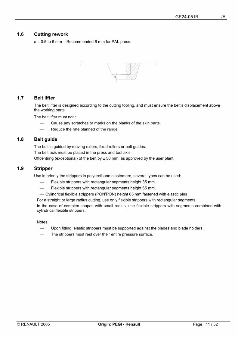
1.5 Blade outputs The notching or shearing blades must overlap the strip edge by 20 mm. When designing belt laying, to prevent aggressive drops, if the cutting output angle < 15°, the blade output must be perpendicular in respect of belt edge (if possible with 5° min opening).
20 m
m5 m
ini
Bel
tw
idth
91°min
Exit 2 > 75°Exit 1 < 15°
Direction ADB
Direction ADB
5 mm
penetration
2 mm
penetration
5 mmpenetration
2 mmpenetration
Bel
twith
ReactionLower part
Upper part
Upper bladesLower blades
5 m
m
pene
tratio
n2 mm
pene
tratio
n
Direction ADB
Ditto
Ditto
Ditto
GE24-051R /A
© RENAULT 2005 Origin: PEGI - Renault Page : 11 / 52
1.6 Cutting rework a = 0.5 to 6 mm � Recommended 6 mm for PAL press.
a
1.7 Belt lifter The belt lifter is designed according to the cutting tooling, and must ensure the belt�s displacement above the working parts.
The belt lifter must not : Cause any scratches or marks on the blanks of the skin parts. Reduce the rate planned of the range.
1.8 Belt guide The belt is guided by moving rollers, fixed rollers or belt guides. The belt axis must be placed in the press and tool axis. Offcentring (exceptional) of the belt by ± 50 mm, as approved by the user plant.
1.9 Stripper Use in priority the strippers in polyurethane elastomere, several types can be used:
Flexible strippers with rectangular segments height 35 mm. Flexible strippers with rectangular segments height 65 mm. Cylindrical flexible strippers (PON�PON) height 65 mm fastened with elastic pins
For a straight or large radius cutting, use only flexible strippers with rectangular segments. In the case of complex shapes with small radius, use flexible strippers with segments combined with cylindrical flexible strippers. Notes: Upon fitting, elastic strippers must be supported against the blades and blade holders. The strippers must rest over their entire pressure surface.

GE24-051R /A
© RENAULT 2005 Origin: PEGI - Renault Page : 12 / 52
Examples of fittings for rectangular and cylindrical flexible strippers.
Fitting of a flexible stripper height 65 mm � standard EM24.54.300 Tool at attack
Tool at bottom stroke
Upper frame
Lower frame
to
Extend blade supporting ranges on frames to maximum
Pinned if blade holder closed
The scrap falls at each press stroke
Keyed if bladeholder open
Fit fasteners outsideblade,seating
Extend blade supporting ranges on frames to maximum
Pinned if blade holder closed
The scrap falls at each press stroke
Keyed if bladeholder open
Fit fasteners outsideblade,seating
Cutting out
Panel edge
Flexible strippers
Detail A
Straight cut
Cylindrical flexible strippers
Notching
Detail A
Cutting out
Panel edge
Flexible strippers
Detail A
Straight cut
Cylindrical flexible strippers
Notching
Detail A
GE24-051R /A
© RENAULT 2005 Origin: PEGI - Renault Page : 13 / 52
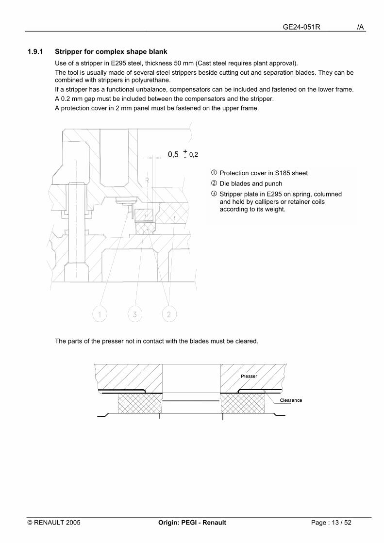
1.9.1 Stripper for complex shape blank Use of a stripper in E295 steel, thickness 50 mm (Cast steel requires plant approval). The tool is usually made of several steel strippers beside cutting out and separation blades. They can be combined with strippers in polyurethane. If a stripper has a functional unbalance, compensators can be included and fastened on the lower frame. A 0.2 mm gap must be included between the compensators and the stripper. A protection cover in 2 mm panel must be fastened on the upper frame.
The parts of the presser not in contact with the blades must be cleared.
" Protection cover in S185 sheet # Die blades and punch
$ Stripper plate in E295 on spring, columned and held by callipers or retainer coils according to its weight.
+ -0,5 0,2
Clearance
Presser
Clearance
Presser
GE24-051R /A
© RENAULT 2005 Origin: PEGI - Renault Page : 14 / 52
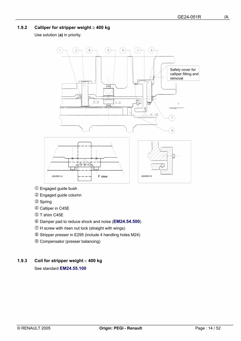
1.9.2 Calliper for stripper weight ≥ 400 kg Use solution (a) in priority.
" Engaged guide bush # Engaged guide column $ Spring % Calliper in C45E & T shim C45E ' Damper pad to reduce shock and noise (EM24.54.500) ( H screw with risen nut lock (straight with wings) ) Stripper presser in E295 (include 4 handling holes M24) * Compensator (presser balancing)
1.9.3 Coil for stripper weight < 400 kg See standard EM24.55.100
F viewsolution a solution b
Safety cover for calliper fitting and removal

GE24-051R /A
© RENAULT 2005 Origin: PEGI - Renault Page : 15 / 52
1.10 Notching specific belt holder If the belt is likely to interfere with the notching blades, add a clip-on belt holder.
Bel
tFR
pos
ition
rail
Belt edge
Belt Fwd direction
Lower blades
ram
stroke Supporting railcarriage
Upper came
200 mini
Rail
30
10
10
30
CUTTING ATOUT
VIEW ALONG F
GE24-051R /A
© RENAULT 2005 Origin: PEGI - Renault Page : 16 / 52
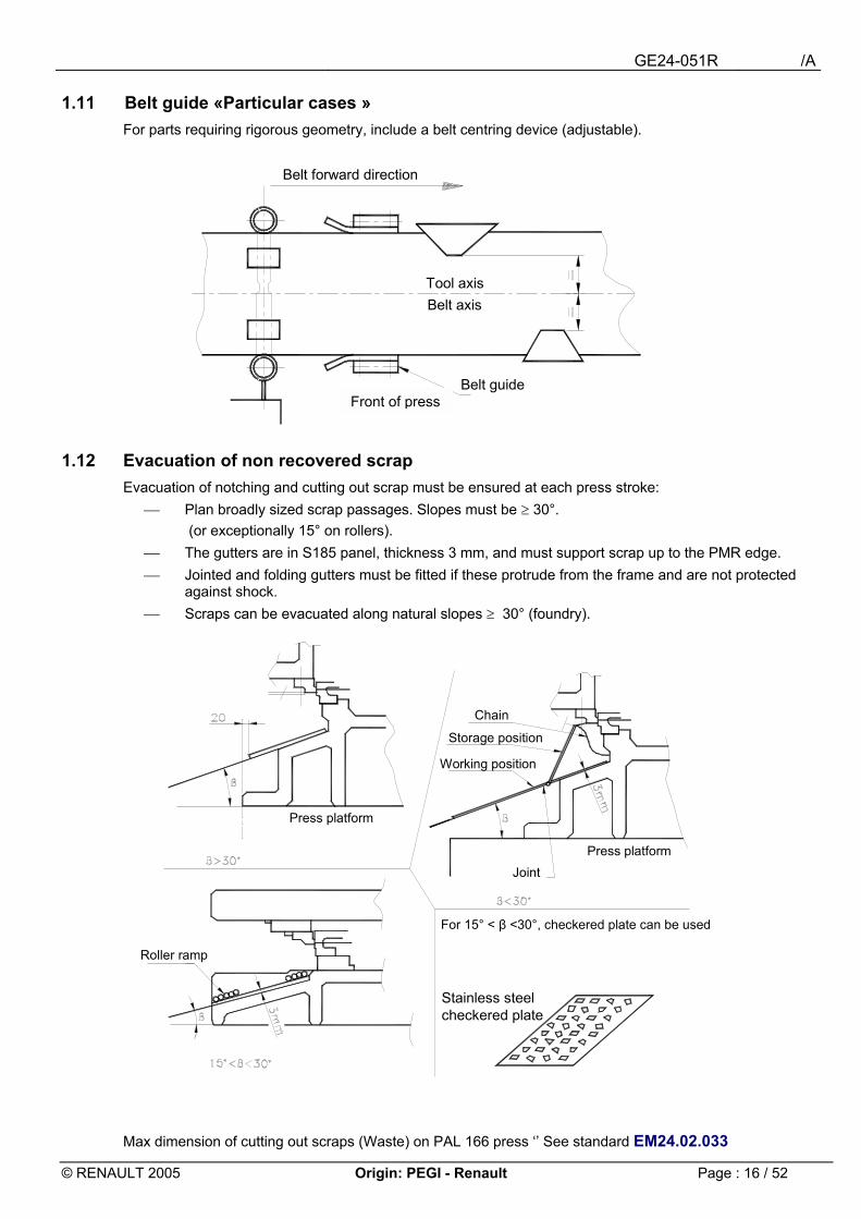
1.11 Belt guide «Particular cases » For parts requiring rigorous geometry, include a belt centring device (adjustable).
1.12 Evacuation of non recovered scrap Evacuation of notching and cutting out scrap must be ensured at each press stroke:
Plan broadly sized scrap passages. Slopes must be ≥ 30°. (or exceptionally 15° on rollers).
The gutters are in S185 panel, thickness 3 mm, and must support scrap up to the PMR edge. Jointed and folding gutters must be fitted if these protrude from the frame and are not protected
against shock. Scraps can be evacuated along natural slopes ≥ 30° (foundry).
Max dimension of cutting out scraps (Waste) on PAL 166 press �� See standard EM24.02.033
Belt forward direction
Tool axisBelt axis
Belt guide
Stainless steel checkered plate
Press platform
Roller ramp
Chain
Storage position
Working position
Joint
For 15° < β <30°, checkered plate can be used
Press platform
Front of press
GE24-051R /A
© RENAULT 2005 Origin: PEGI - Renault Page : 17 / 52
2 Fitting under PAL � PAC press
2.1 Conditions of evacuation of blanks and scraps The evacuation direction of the blanks and scrap must be defined according to the type of press. Beware front of press: see technical sheet EM24.03.200 • Reminder: no positive ejection.
2.1.1 Blank cut 1 stroke/1 blank Blank collection between post is performed by gravity, magnetic conveyor, or motorised roller ramp. Avoid separating the scrap and part at the same station (part remaining supported on blades).
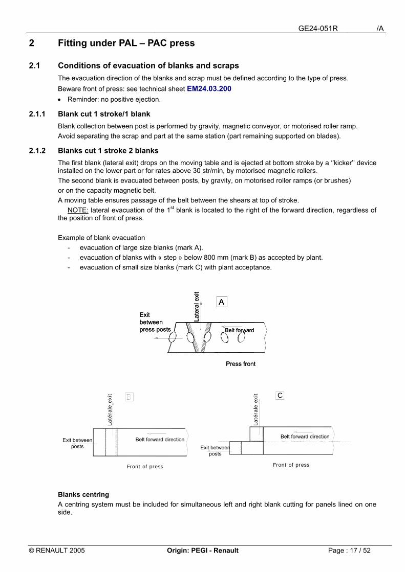
2.1.2 Blanks cut 1 stroke 2 blanks The first blank (lateral exit) drops on the moving table and is ejected at bottom stroke by a ��kicker�� device installed on the lower part or for rates above 30 str/min, by motorised magnetic rollers. The second blank is evacuated between posts, by gravity, on motorised roller ramps (or brushes) or on the capacity magnetic belt. A moving table ensures passage of the belt between the shears at top of stroke. NOTE: lateral evacuation of the 1st blank is located to the right of the forward direction, regardless of the position of front of press. Example of blank evacuation
- evacuation of large size blanks (mark A). - evacuation of blanks with « step » below 800 mm (mark B) as accepted by plant. - evacuation of small size blanks (mark C) with plant acceptance.
Blanks centring A centring system must be included for simultaneous left and right blank cutting for panels lined on one side.
AExit between press posts
Late
ral e
xit
Belt forward
Press front
AAExit between press posts
Late
ral e
xit
Belt forward
Press front
Front of press
C
Front of press
Laté
rale
exi
t
Laté
rale
exi
t
Exit between posts
Belt forward directionExit between
posts
Belt forward direction
GE24-051R /A
© RENAULT 2005 Origin: PEGI - Renault Page : 18 / 52
2.2 Frames See master drawing GE24-014R Plan: - 2 rolling paths under lower frames fitted without riser. (see Press T.S. and chapter 3).
- refitting of lower frame soles for tool pusher coupling. - properly spaced lower handling eyes for passage of slings. - bearing ranges beyond the implantations of blades on lower and upper frames. - 4 ranges for elastic spacers height 160. - 4 columns Ø 100 in lower part. - 4 bushes engaged without inserts H7/g6.
2.2.1 Tool weight In all cases, the weight of the tools must be below: - 20 tonnes for PAL�� presses in FLINS. -25 tonnes for PAL�� presses in other plants. Take into account the inter-plant backup plan.
2.3 Standardising of connections
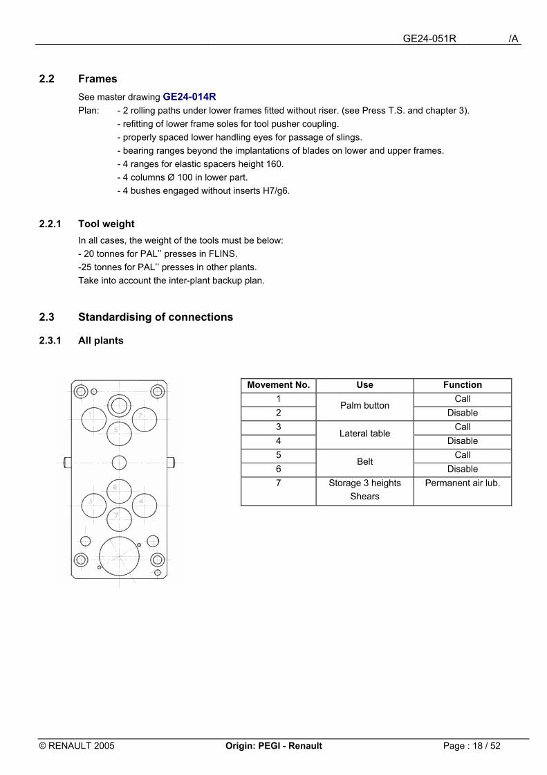
2.3.1 All plants
Movement No. Use Function 1 Call 2
Palm button Disable
3 Call 4
Lateral table Disable
5 Call 6
Belt Disable
7 Storage 3 heights Shears
Permanent air lub.
GE24-051R /A
© RENAULT 2005 Origin: PEGI - Renault Page : 19 / 52
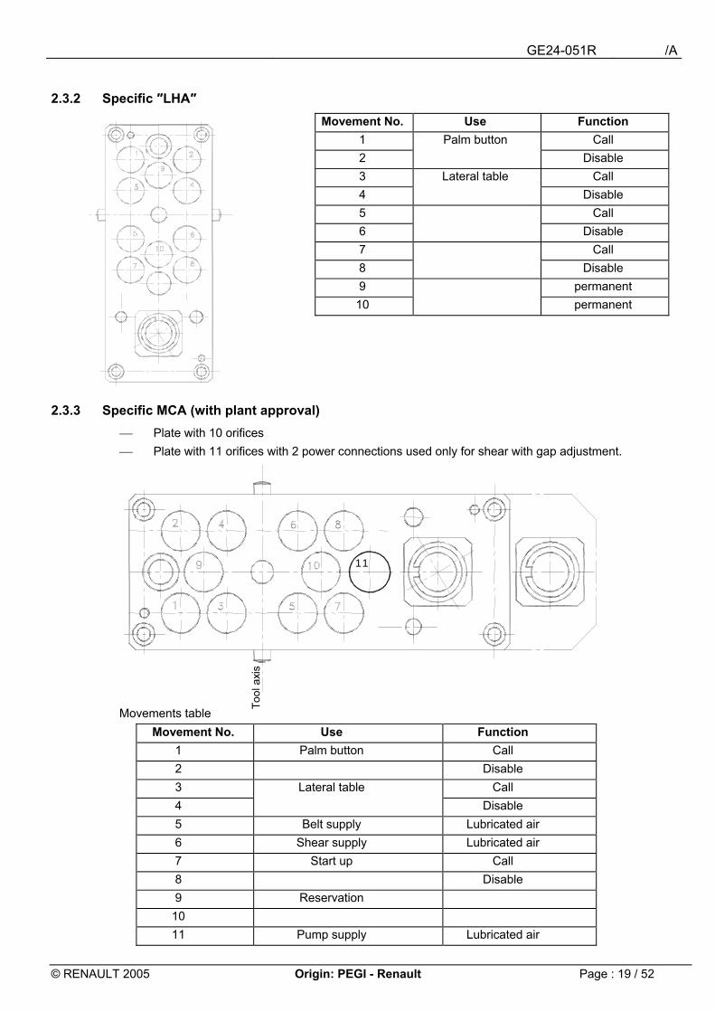
2.3.2 Specific ″LHA″
2.3.3 Specific MCA (with plant approval) Plate with 10 orifices Plate with 11 orifices with 2 power connections used only for shear with gap adjustment.
Movements table Movement No. Use Function
1 Palm button Call 2 Disable 3 Lateral table Call 4 Disable 5 Belt supply Lubricated air 6 Shear supply Lubricated air 7 Start up Call 8 Disable 9 Reservation
10 11 Pump supply Lubricated air
Movement No. Use Function 1 Palm button Call 2 Disable 3 Lateral table Call 4 Disable 5 Call 6 Disable 7 Call 8 Disable 9 permanent 10 permanent
11
Tool
axis
GE24-051R /A
© RENAULT 2005 Origin: PEGI - Renault Page : 20 / 52
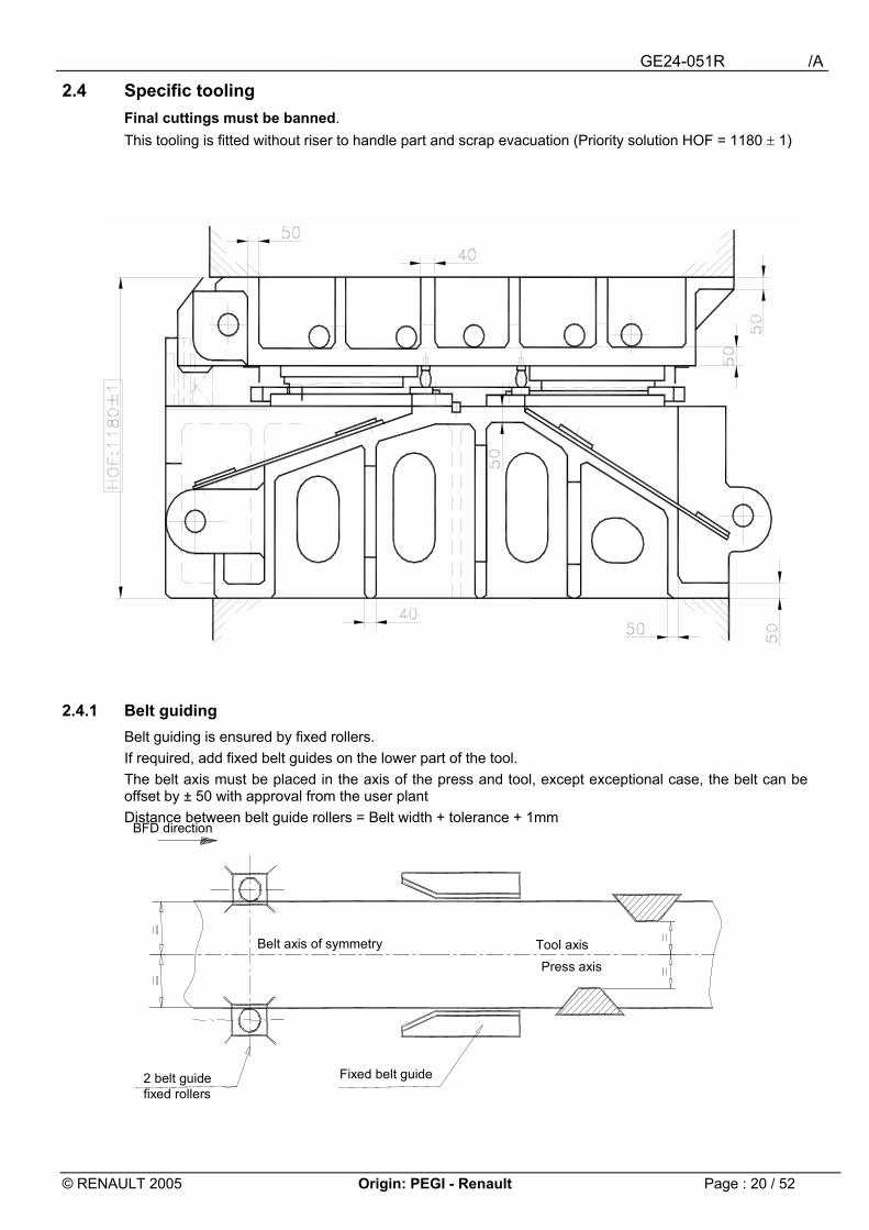
2.4 Specific tooling Final cuttings must be banned. This tooling is fitted without riser to handle part and scrap evacuation (Priority solution HOF = 1180 ± 1)
2.4.1 Belt guiding Belt guiding is ensured by fixed rollers. If required, add fixed belt guides on the lower part of the tool. The belt axis must be placed in the axis of the press and tool, except exceptional case, the belt can be offset by ± 50 with approval from the user plant Distance between belt guide rollers = Belt width + tolerance + 1mm
BFD direction
Press axis Tool axis
Fixed belt guide 2 belt guide fixed rollers
Belt axis of symmetry

GE24-051R /A
© RENAULT 2005 Origin: PEGI - Renault Page : 21 / 52
2.4.2 Belt lifter It is made of a light and rigid structure, in mechanically welded profile (square tube). It is fitted with spring retaining screws in elastomere, for a stroke ≤ 20 mm and precompressed
assemblies with stroke > 20 mm, the moving frame will be folded by elastic compensators fitted on the upper part.
The belt lifter stroke is determined according to proper passage of the belt. It is fitted with cylindrical rollers ∅ 50 (Standard EM24.57.500) and deflector(s) in brass sheet
(blank for skin part) to ensure belt entrance and displacement. For other blanks, the deflector in steel panel thickness 3 mm is welded (or screwed) on the belt lifting structure.
No paint on metallic structure. Example, tool at bottom stroke:
Ft axis
Bel
twid
th
Brass sheet deflector th 2.5mm (if required)
Nylstop nut
A cross-section
Clear if required
welded nutRoller
Belt
lift
Feed
hei
ght
Ret
aine
r scr
ew
Elastic element
Ft axis
Bel
twid
th
Brass sheet deflector th 2.5mm (if required)
Nylstop nut
A cross-section
Clear if required
welded nutRoller
Belt
lift
Feed
hei
ght
Ret
aine
r scr
ew
Elastic element
GE24-051R /A
© RENAULT 2005 Origin: PEGI - Renault Page : 22 / 52
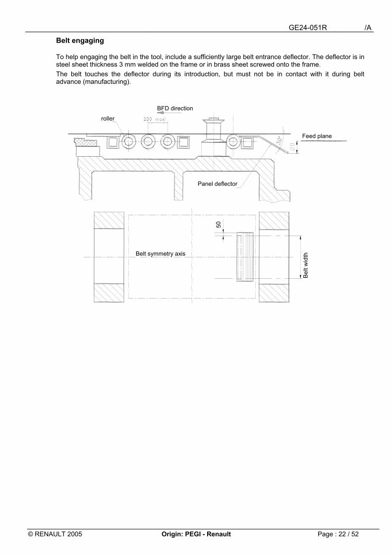
Belt engaging To help engaging the belt in the tool, include a sufficiently large belt entrance deflector. The deflector is in steel sheet thickness 3 mm welded on the frame or in brass sheet screwed onto the frame. The belt touches the deflector during its introduction, but must not be in contact with it during belt advance (manufacturing).
Belt
wid
th
50
Belt symmetry axis
Panel deflector
BFD direction
roller
Feed plane
GE24-051R /A
© RENAULT 2005 Origin: PEGI - Renault Page : 23 / 52
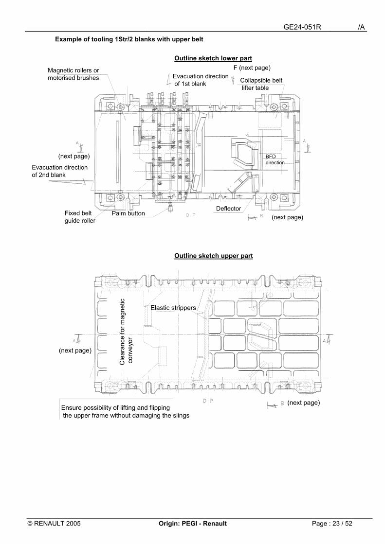
Example of tooling 1Str/2 blanks with upper belt
Outline sketch lower part
Outline sketch upper part
Magnetic rollers or motorised brushes
DeflectorPalm buttonFixed belt
guide roller
Evacuation direction of 2nd blank
(next page)
Collapsible beltlifter table
F (next page)Evacuation directionof 1st blank
(next page) BFD direction
Ensure possibility of lifting and flippingthe upper frame without damaging the slings
(next page)
Cle
aran
ce fo
r mag
netic
conv
eyor
Elastic strippers
(next page)
GE24-051R /A
© RENAULT 2005 Origin: PEGI - Renault Page : 24 / 52
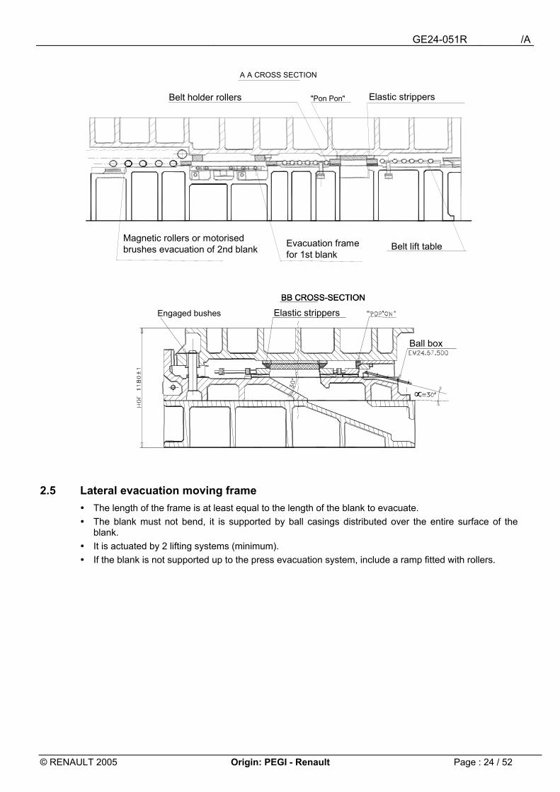
2.5 Lateral evacuation moving frame ! The length of the frame is at least equal to the length of the blank to evacuate. ! The blank must not bend, it is supported by ball casings distributed over the entire surface of the
blank. ! It is actuated by 2 lifting systems (minimum). ! If the blank is not supported up to the press evacuation system, include a ramp fitted with rollers.
Evacuation frame for 1st blank
Belt lift table
Belt holder rollers
A A CROSS SECTION
"Pon Pon" Elastic strippers
Magnetic rollers or motorised brushes evacuation of 2nd blank
∝
BB CROSS-SECTION
∝
BB CROSS-SECTION
Engaged bushes
Ball box
Elastic strippers
GE24-051R /A
© RENAULT 2005 Origin: PEGI - Renault Page : 25 / 52
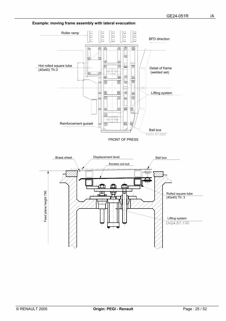
Example: moving frame assembly with lateral evacuation
Roller ramp
FRONT OF PRESS
BFD direction
Hot rolled square tube (40x40) Th:3 Detail of frame
(welded set)
Lifting system
Reinforcement gusset
Ball box
Feed
pla
ne h
eigh
t 790 Rolled square tube
(40x40) Th: 3
Ball box
Access cut-out
Displacement levelBrass sheet
Lifting system
GE24-051R /A
© RENAULT 2005 Origin: PEGI - Renault Page : 26 / 52
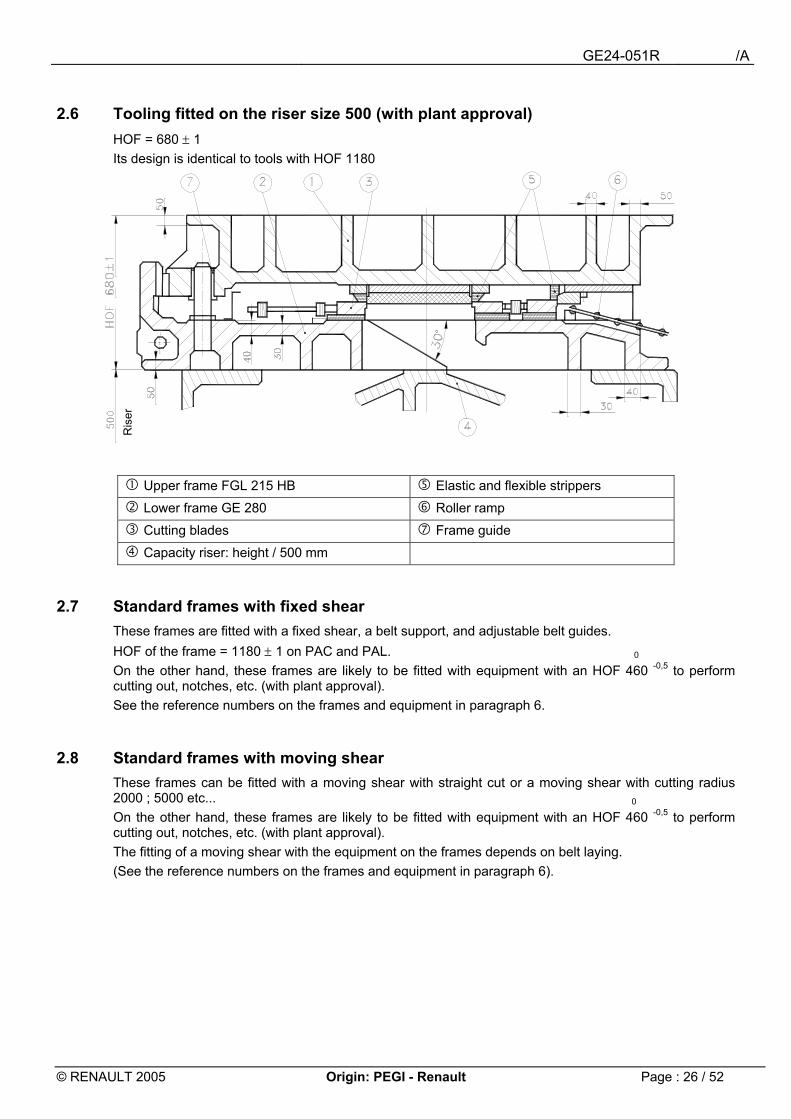
2.6 Tooling fitted on the riser size 500 (with plant approval) HOF = 680 ± 1 Its design is identical to tools with HOF 1180
" Upper frame FGL 215 HB & Elastic and flexible strippers
# Lower frame GE 280 ' Roller ramp
$ Cutting blades ( Frame guide
% Capacity riser: height / 500 mm
2.7 Standard frames with fixed shear These frames are fitted with a fixed shear, a belt support, and adjustable belt guides. HOF of the frame = 1180 ± 1 on PAC and PAL. 0 On the other hand, these frames are likely to be fitted with equipment with an HOF 460 -0,5 to perform cutting out, notches, etc. (with plant approval). See the reference numbers on the frames and equipment in paragraph 6.
2.8 Standard frames with moving shear These frames can be fitted with a moving shear with straight cut or a moving shear with cutting radius 2000 ; 5000 etc... 0 On the other hand, these frames are likely to be fitted with equipment with an HOF 460 -0,5 to perform cutting out, notches, etc. (with plant approval). The fitting of a moving shear with the equipment on the frames depends on belt laying. (See the reference numbers on the frames and equipment in paragraph 6).
Ris
er
GE24-051R /A
© RENAULT 2005 Origin: PEGI - Renault Page : 27 / 52
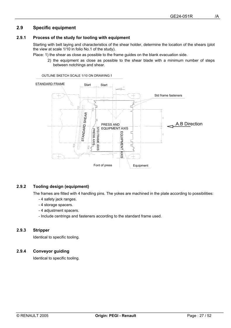
2.9 Specific equipment
2.9.1 Process of the study for tooling with equipment Starting with belt laying and characteristics of the shear holder, determine the location of the shears (plot the view at scale 1/10 in folio No.1 of the study). Place: 1) the shear as close as possible to the frame guides on the blank evacuation side.
2) the equipment as close as possible to the shear blade with a minimum number of steps between notchings and shear.
2.9.2 Tooling design (equipment) The frames are fitted with 4 handling pins. The yokes are machined in the plate according to possibilities:
- 4 safety jack ranges. - 4 storage spacers. - 4 adjustment spacers. - Include centrings and fasteners according to the standard frame used.
2.9.3 Stripper Identical to specific tooling.
2.9.4 Conveyor guiding Identical to specific tooling.
.A.B Direction
OUTLINE SKETCH SCALE 1/10 ON DRAWING:1
Font of press
EQ
UIP
ME
NT A
XIS
Equipment
Std frame fasteners
PRESS AND EQUIPMENT AXISP
RE
SS
AXIS
STD
FRA
ME
AXIS
STAN
DA
RD
SH
EAR
StartSTANDARD FRAME Start
GE24-051R /A
© RENAULT 2005 Origin: PEGI - Renault Page : 28 / 52
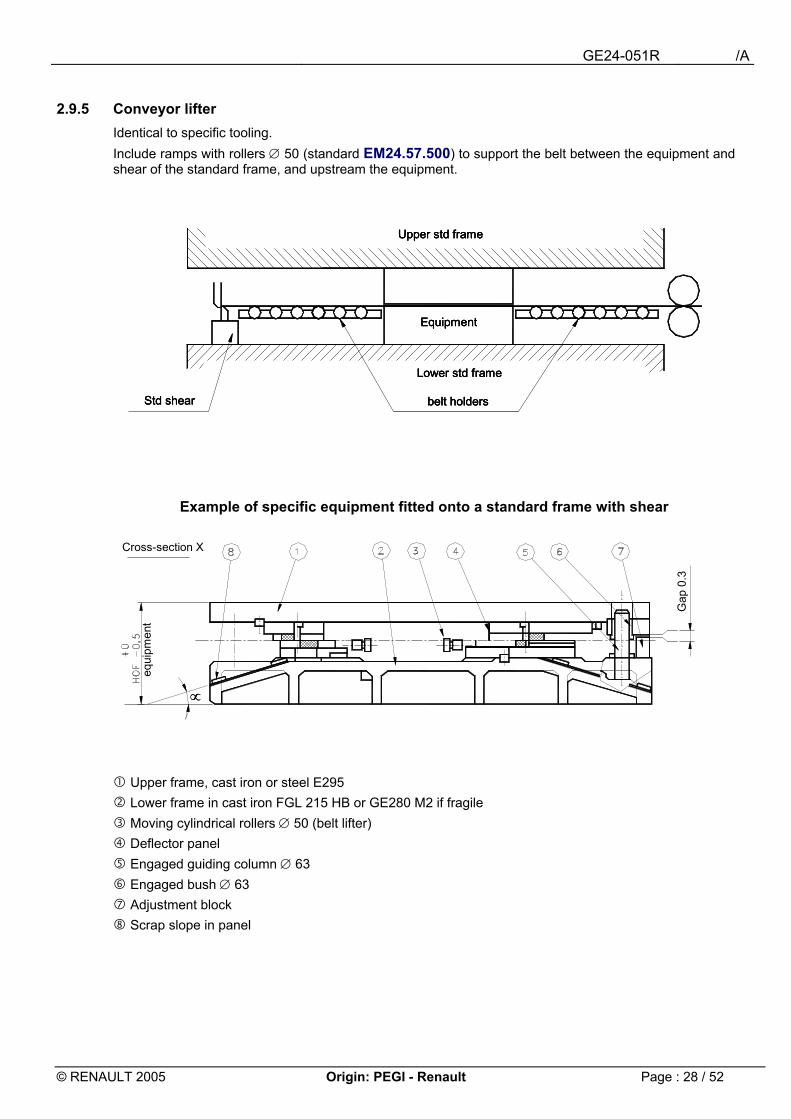
2.9.5 Conveyor lifter Identical to specific tooling. Include ramps with rollers ∅ 50 (standard EM24.57.500) to support the belt between the equipment and shear of the standard frame, and upstream the equipment.
Example of specific equipment fitted onto a standard frame with shear
" Upper frame, cast iron or steel E295 # Lower frame in cast iron FGL 215 HB or GE280 M2 if fragile $ Moving cylindrical rollers ∅ 50 (belt lifter) % Deflector panel & Engaged guiding column ∅ 63 ' Engaged bush ∅ 63 ( Adjustment block ) Scrap slope in panel
Upper std frame
belt holdersStd shear
Lower std frame
Equipment
Upper std frame
belt holdersStd shear
Lower std frame
Equipment
Upper std frame
belt holdersStd shear
Lower std frame
Equipment
∝∝
Cross-section X
equi
pmen
t
Gap
0.3
GE24-051R /A
© RENAULT 2005 Origin: PEGI - Renault Page : 29 / 52
2.10 Standard frame with 2 moving shears These frames are fitted with two straight cutting shears with independent adjustment (longitudinal and angular). The position of both shears on the frames changes according to the belt laying. The 1st blank is evacuated between the 2 shears by a moving system (table actuated by elevators, and possibly a palm button) and the 2nd blank after the exit shear on a train of brushes or rollers or directly with the evacuation belt. 0 On the other hand, these frames are likely to be fitted with equipment with HOF 460 -0,5 (See the reference numbers on the frames and equipment in paragraph 6).
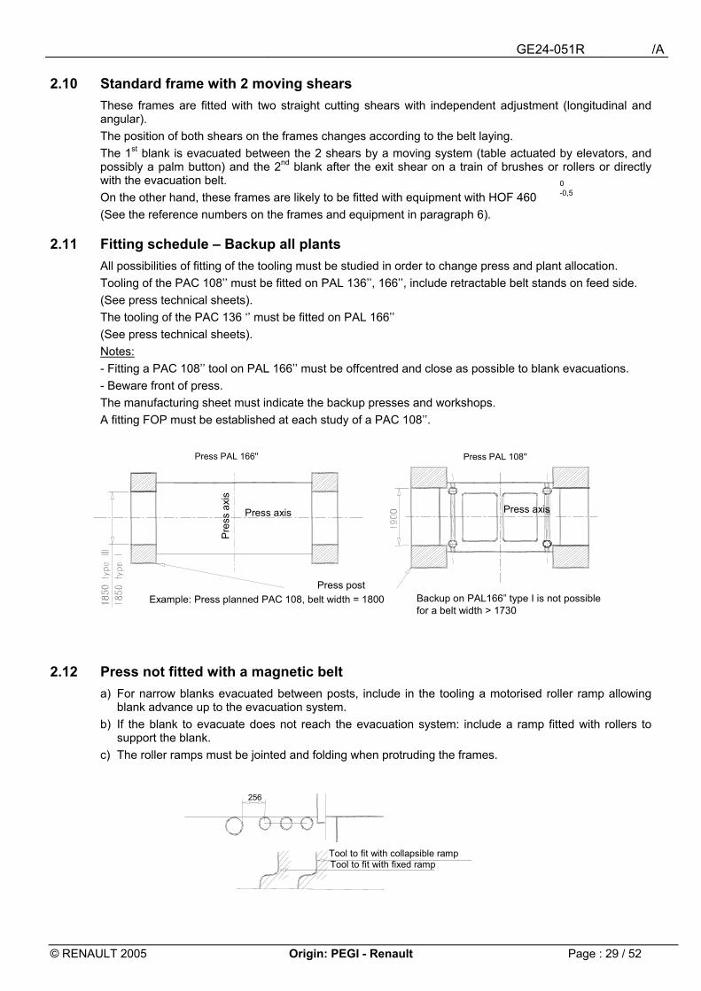
2.11 Fitting schedule � Backup all plants All possibilities of fitting of the tooling must be studied in order to change press and plant allocation. Tooling of the PAC 108�� must be fitted on PAL 136��, 166��, include retractable belt stands on feed side. (See press technical sheets). The tooling of the PAC 136 �� must be fitted on PAL 166�� (See press technical sheets). Notes: - Fitting a PAC 108�� tool on PAL 166�� must be offcentred and close as possible to blank evacuations. - Beware front of press. The manufacturing sheet must indicate the backup presses and workshops. A fitting FOP must be established at each study of a PAC 108��.
2.12 Press not fitted with a magnetic belt a) For narrow blanks evacuated between posts, include in the tooling a motorised roller ramp allowing
blank advance up to the evacuation system. b) If the blank to evacuate does not reach the evacuation system: include a ramp fitted with rollers to
support the blank. c) The roller ramps must be jointed and folding when protruding the frames.
Press PAL 108''Press PAL 166''
Backup on PAL166� type I is not possiblefor a belt width > 1730
Pres
s ax
is
Press axis Press axis
Press postExample: Press planned PAC 108, belt width = 1800
Tool to fit with collapsible rampTool to fit with fixed ramp
256
GE24-051R /A
© RENAULT 2005 Origin: PEGI - Renault Page : 30 / 52
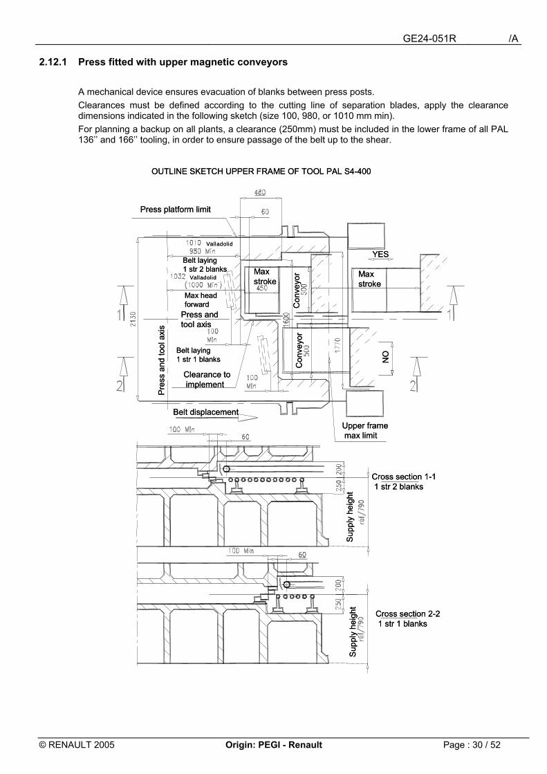
2.12.1 Press fitted with upper magnetic conveyors A mechanical device ensures evacuation of blanks between press posts. Clearances must be defined according to the cutting line of separation blades, apply the clearance dimensions indicated in the following sketch (size 100, 980, or 1010 mm min). For planning a backup on all plants, a clearance (250mm) must be included in the lower frame of all PAL 136�� and 166�� tooling, in order to ensure passage of the belt up to the shear.
Valladolid
Valladolid
OUTLINE SKETCH UPPER FRAME OF TOOL PAL S4-400
Cross section 1-11 str 2 blanks
Sup
ply
heig
ht
Upper framemax limit
Belt displacement
Max stroke
Clearance toimplement
Press and tool axis
Max head forward
Belt laying 1 str 2 blanks
Press platform limit
Belt laying 1 str 1 blanks
Pre
ss a
nd to
ol a
xis
Con
veyo
rC
onve
yor
YES
NO
Cross section 2-21 str 1 blanks
Sup
ply
heig
ht
Max stroke
Valladolid
Valladolid
OUTLINE SKETCH UPPER FRAME OF TOOL PAL S4-400
Cross section 1-11 str 2 blanks
Sup
ply
heig
ht
Upper framemax limit
Belt displacement
Max stroke
Clearance toimplement
Press and tool axis
Max head forward
Belt laying 1 str 2 blanks
Press platform limit
Belt laying 1 str 1 blanks
Pre
ss a
nd to
ol a
xis
Con
veyo
rC
onve
yor
YES
NO
Cross section 2-21 str 1 blanks
Sup
ply
heig
ht
Max stroke
GE24-051R /A
© RENAULT 2005 Origin: PEGI - Renault Page : 31 / 52
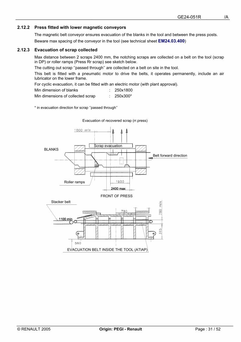
2.12.2 Press fitted with lower magnetic conveyors The magnetic belt conveyor ensures evacuation of the blanks in the tool and between the press posts. Beware max spacing of the conveyor in the tool (see technical sheet EM24.03.400)
2.12.3 Evacuation of scrap collected Max distance between 2 scraps 2400 mm, the notching scraps are collected on a belt on the tool (scrap in DP) or roller ramps (Press Rr scrap) see sketch below. The cutting out scrap ��passed through�� are collected on a belt on site in the tool. This belt is fitted with a pneumatic motor to drive the belts, it operates permanently, include an air lubricator on the lower frame. For cyclic evacuation, it can be fitted with an electric motor (with plant approval). Min dimension of blanks : 250x1800 Min dimensions of collected scrap : 250x300* * in evacuation direction for scrap ��passed through��
2400 max
1100 min
2400 max
1100 min
Evacuation of recovered scrap (rr.press)
EVACUATION BELT INSIDE THE TOOL (ATIAP)
Stacker beltFRONT OF PRESS
Roller ramps
BLANKS
Belt forward direction
Scrap evacuation
GE24-051R /A
© RENAULT 2005 Origin: PEGI - Renault Page : 32 / 52
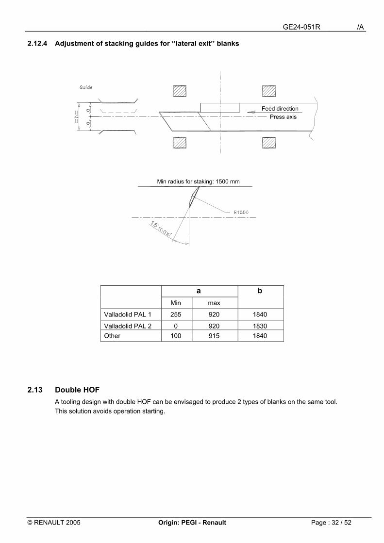
2.12.4 Adjustment of stacking guides for ��lateral exit�� blanks
a b Min max
Valladolid PAL 1 255 920 1840
Valladolid PAL 2 0 920 1830 Other 100 915 1840
2.13 Double HOF A tooling design with double HOF can be envisaged to produce 2 types of blanks on the same tool. This solution avoids operation starting.
Min radius for staking: 1500 mm
Feed directionPress axis
GE24-051R /A
© RENAULT 2005 Origin: PEGI - Renault Page : 33 / 52
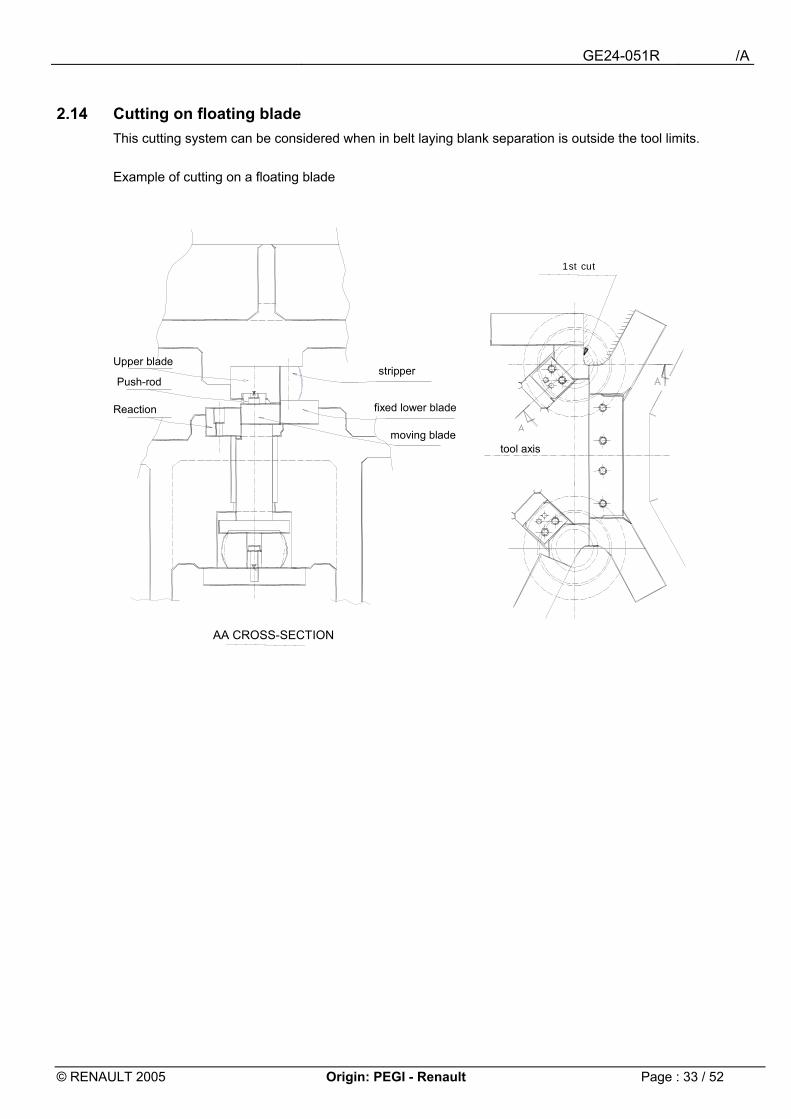
2.14 Cutting on floating blade This cutting system can be considered when in belt laying blank separation is outside the tool limits. Example of cutting on a floating blade
1st cut
Upper blade
tool axis
AA CROSS-SECTION
moving blade
fixed lower blade
stripper
Reaction
Push-rod
GE24-051R /A
© RENAULT 2005 Origin: PEGI - Renault Page : 34 / 52
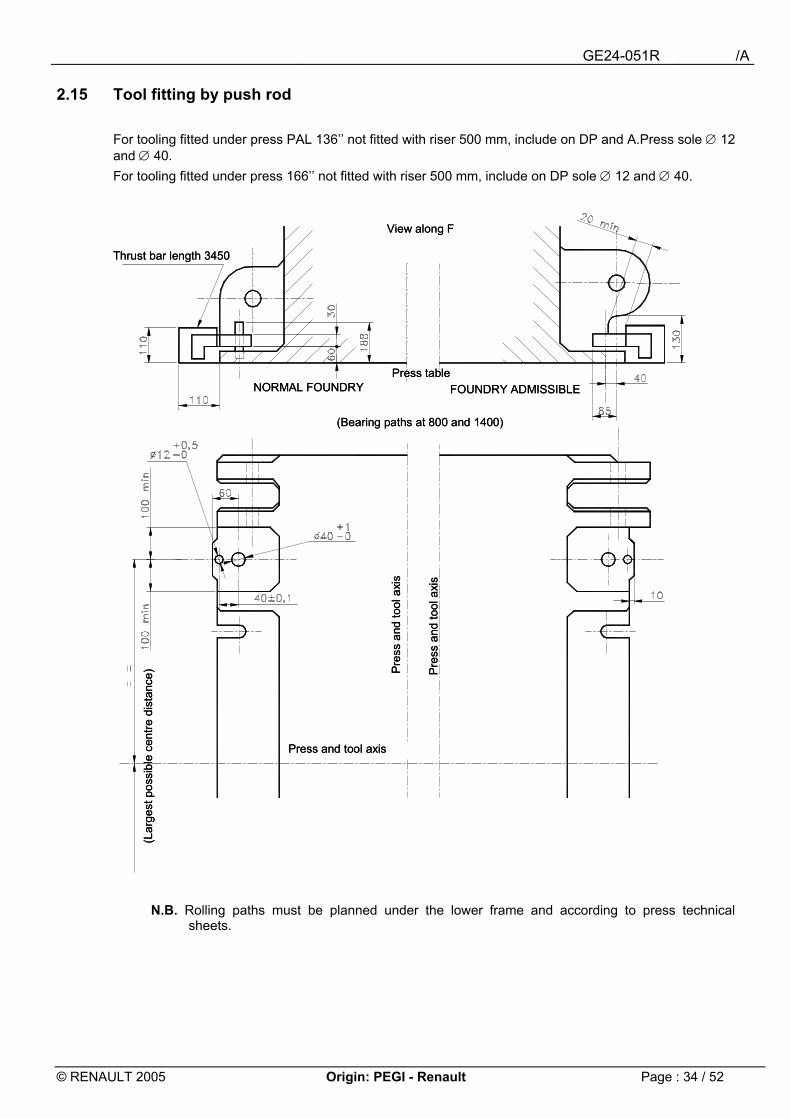
2.15 Tool fitting by push rod For tooling fitted under press PAL 136�� not fitted with riser 500 mm, include on DP and A.Press sole ∅ 12 and ∅ 40. For tooling fitted under press 166�� not fitted with riser 500 mm, include on DP sole ∅ 12 and ∅ 40.
N.B. Rolling paths must be planned under the lower frame and according to press technical sheets.
View along F
Press and tool axis
(Lar
gest
pos
sibl
e ce
ntre
dis
tanc
e)
(Bearing paths at 800 and 1400)
FOUNDRY ADMISSIBLENORMAL FOUNDRYPress table
Thrust bar length 3450
Pre
ss a
nd to
ol a
xis
Pre
ss a
nd to
ol a
xis
View along F
Press and tool axis
(Lar
gest
pos
sibl
e ce
ntre
dis
tanc
e)
(Bearing paths at 800 and 1400)
FOUNDRY ADMISSIBLENORMAL FOUNDRYPress table
Thrust bar length 3450
Pre
ss a
nd to
ol a
xis
Pre
ss a
nd to
ol a
xis
GE24-051R /A
© RENAULT 2005 Origin: PEGI - Renault Page : 35 / 52
3 Fitting under PAVAR press
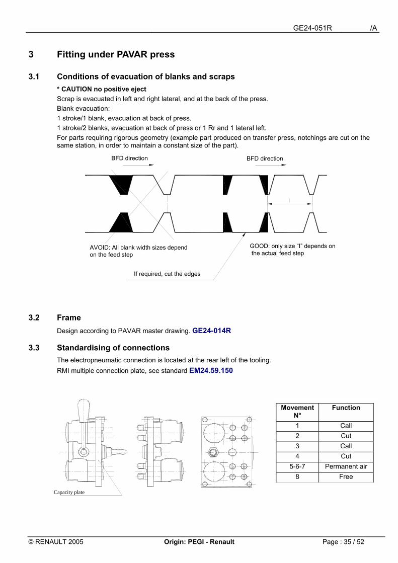
3.1 Conditions of evacuation of blanks and scraps * CAUTION no positive eject Scrap is evacuated in left and right lateral, and at the back of the press. Blank evacuation: 1 stroke/1 blank, evacuation at back of press. 1 stroke/2 blanks, evacuation at back of press or 1 Rr and 1 lateral left. For parts requiring rigorous geometry (example part produced on transfer press, notchings are cut on the same station, in order to maintain a constant size of the part).
3.2 Frame Design according to PAVAR master drawing. GE24-014R
3.3 Standardising of connections The electropneumatic connection is located at the rear left of the tooling. RMI multiple connection plate, see standard EM24.59.150
Movement N°
Function
1 Call 2 Cut 3 Call 4 Cut
5-6-7 Permanent air 8 Free
If required, cut the edges
BFD direction
AVOID: All blank width sizes depend on the feed step
GOOD: only size �I� depends onthe actual feed step
BFD direction
Capacity plate
GE24-051R /A
© RENAULT 2005 Origin: PEGI - Renault Page : 36 / 52
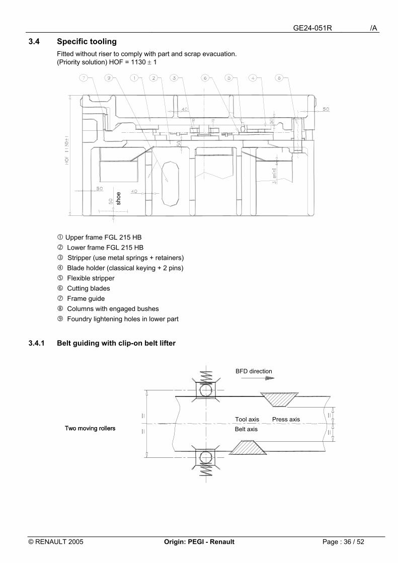
3.4 Specific tooling Fitted without riser to comply with part and scrap evacuation. (Priority solution) HOF = 1130 ± 1
" Upper frame FGL 215 HB # Lower frame FGL 215 HB $ Stripper (use metal springs + retainers) % Blade holder (classical keying + 2 pins) & Flexible stripper ' Cutting blades ( Frame guide ) Columns with engaged bushes * Foundry lightening holes in lower part
3.4.1 Belt guiding with clip-on belt lifter
shoe
Two moving rollersTwo moving rollers Belt axis
BFD direction
Tool axis Press axis
GE24-051R /A
© RENAULT 2005 Origin: PEGI - Renault Page : 37 / 52
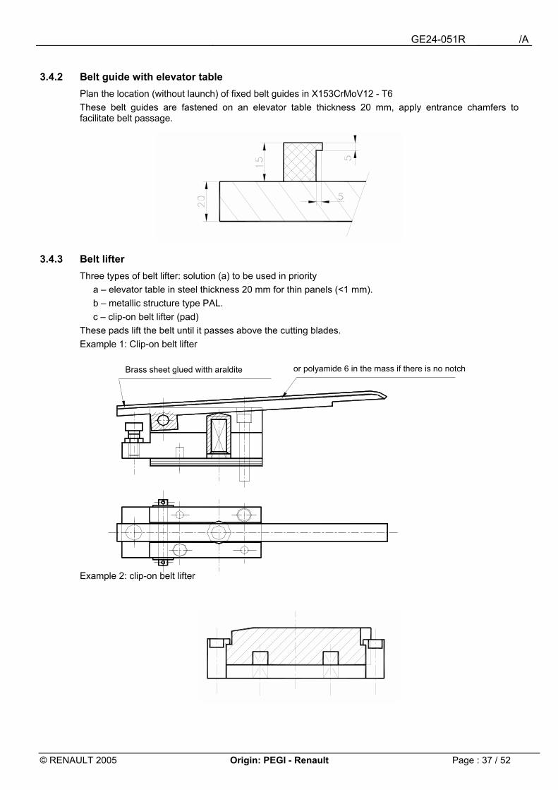
3.4.2 Belt guide with elevator table Plan the location (without launch) of fixed belt guides in X153CrMoV12 - T6 These belt guides are fastened on an elevator table thickness 20 mm, apply entrance chamfers to facilitate belt passage.
3.4.3 Belt lifter Three types of belt lifter: solution (a) to be used in priority
a � elevator table in steel thickness 20 mm for thin panels (<1 mm). b � metallic structure type PAL. c � clip-on belt lifter (pad)
These pads lift the belt until it passes above the cutting blades. Example 1: Clip-on belt lifter
Example 2: clip-on belt lifter
Brass sheet glued witth araldite or polyamide 6 in the mass if there is no notch

GE24-051R /A
© RENAULT 2005 Origin: PEGI - Renault Page : 38 / 52
Example of tooling HOF 630mm
3.5 Lateral evacuation Some presses are not fitted with the lateral evacuation system, refer to the Press technical sheet. The blank evacuation zone is located to the left of belt advance. The blank to evacuate is received on a magnetic belt fixed to the tool. Max dimension of the blank in the step direction: 500mm.
As close as possibleto blades
½ outline sketch lower partB
elt f
orw
ard
½ outline sketch upper part
Cross-section: A Cross-section: B
GE24-051R /A
© RENAULT 2005 Origin: PEGI - Renault Page : 39 / 52
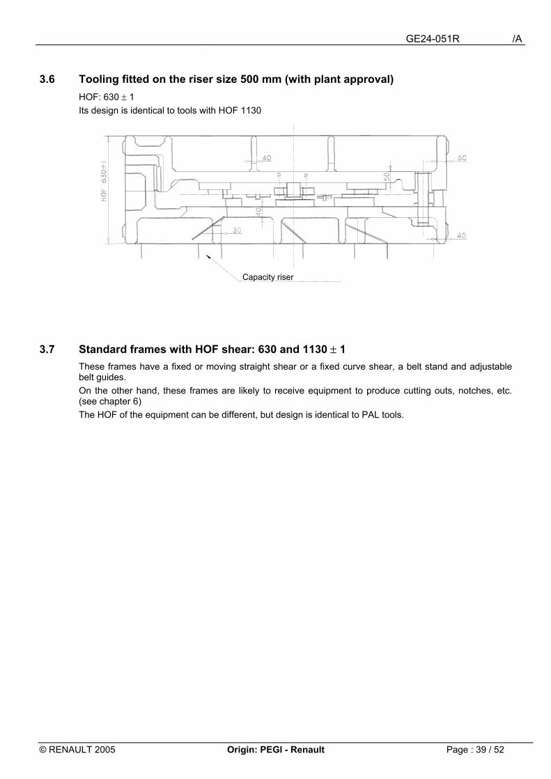
3.6 Tooling fitted on the riser size 500 mm (with plant approval) HOF: 630 ± 1 Its design is identical to tools with HOF 1130
3.7 Standard frames with HOF shear: 630 and 1130 ± 1 These frames have a fixed or moving straight shear or a fixed curve shear, a belt stand and adjustable belt guides. On the other hand, these frames are likely to receive equipment to produce cutting outs, notches, etc. (see chapter 6)
The HOF of the equipment can be different, but design is identical to PAL tools.
Capacity riser
GE24-051R /A
© RENAULT 2005 Origin: PEGI - Renault Page : 40 / 52
4 Fitting under press 4000 kN X 2 (2.5)
4.1 Specific 1-blank tooling Max dimension of frames 2000 (2500) x1400 - HOF 880 ± 1. Use master drawings GE24-015R (progressive) for constructing frames. For Valladolid, the tooling is fitted on a riser with an HOF 680 ± 1. Use master drawings specific to Valladolid.
4.2 Specific 2-blank tooling It can include the protrusion strokes, notchings, shearing of 2 blanks, one of which is evacuated between the posts, and the other at the front of press. (No palm button equipment).
4.3 Standard frames with fixed shear These frames are fitted with a fixed shear and adjustable belt guides. HOF of frames: 680 ± 1 These frames are not fitted with equipment.
4.4 Standard frames with 1 moving shear These frames are not fitted with equipment.
4.5 Conditions of evacuation of blanks and scraps Refer to press technical sheets. a) Between left posts: blanks or scrap of skeletons (max dimension 600x300mm). b) Between left post and on front of press: 2 blanks c) Consider the blank position on the stamping press.
4.6 Connections Refer to press technical sheets.
4.7 Cutting elements See paragraph 1, no refilled blades.
4.8 Stripper Belt extraction is ensured by a stripper plate actuated by equipment with spring or flexible strippers. Stripper retaining (See standard EM24.55.100). Plan a protection panel around the stripper and ensure proper balancing of the stripper.
4.9 Belt guiding See master drawing for progressive tool (GE24-015R) To ensure a precise step, pilots can be integrated into the stripper.
4.10 Belt lifter Passage of the belt above the blades is ensured by a belt lifter plate actuated by springs or support pads (see Pavar) The belt must be supported over the entire length of the tooling.
4.11 Belt advance check Use the belt forward system for progressive tools.
GE24-051R /A
© RENAULT 2005 Origin: PEGI - Renault Page : 41 / 52
5 Fitting under press 2500 or 4000 kN x 1.6
5.1 Tooling specific to a part This tooling is fitted without riser HOF 530 ± 1 Dimension of frames 1550x1200 Tooling specific to 2 blanks. It can include the destacking protrusion stroke, notchings, shearing of 2 blanks, one of which is evacuated between the posts and the other laterally. (No palm button equipment). Use master drawings GE24-014R
5.2 Standard frames with fixed shear These frames are fitted with a fixed shear and adjustable belt guides. HOF of frames: 380 ± 1 These frames are not fitted with equipment.
5.3 Standardised frames with 1 moving shear These frames are not fitted with equipment.
5.4 Conditions of evacuation of blanks and scraps a) between left posts : skeleton blanks or scrap b) Through the table opening : scrap c) between left post and on back of press : 2 blanks d) blank evacuation height in lateral part : 240 mm e) evacuation height of blanks between posts : 250 mm Refer to press technical sheets.
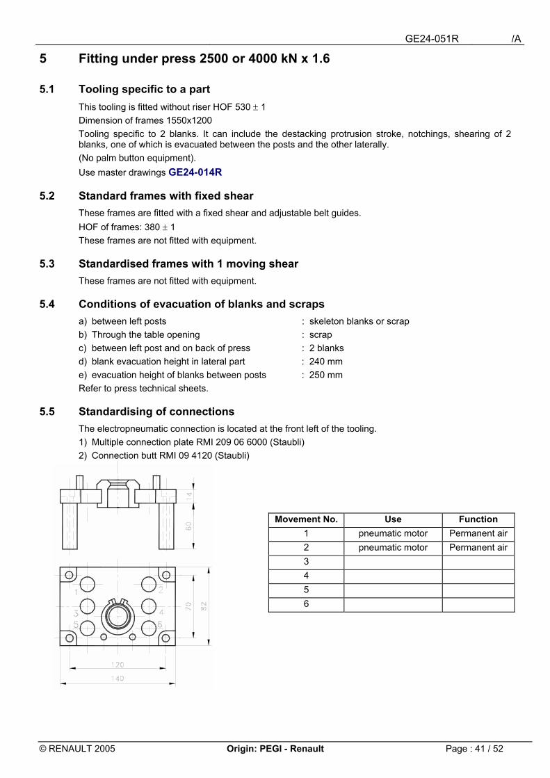
5.5 Standardising of connections The electropneumatic connection is located at the front left of the tooling. 1) Multiple connection plate RMI 209 06 6000 (Staubli) 2) Connection butt RMI 09 4120 (Staubli)
Movement No. Use Function 1 pneumatic motor Permanent air 2 pneumatic motor Permanent air 3 4 5 6
GE24-051R /A
© RENAULT 2005 Origin: PEGI - Renault Page : 42 / 52
5.6 Cutting elements See paragraph 1, no refilled blade.
5.7 Stripper Belt extraction is ensured by a stripper plate actuated by equipment with retaining spring or flexible strippers. Stripper retaining (See standard EM24.55.100) Include a protection panel around the stripper and ensure proper balancing of the stripper.
5.8 Belt guiding See master drawing for progressive tool (GE24-014R)
5.9 Belt lifter Passage of the belt above the blades is ensured by a belt lifter plate actuated by springs or support pads. The belt must be supported over the entire length of the tooling.
5.10 Blank evacuation The blanks are supported by bars fastened between the cutting blade and the press evacuation system (belt). The blanks are evacuated by magnetic rollers (∅ 50) driven by a pneumatic motor.
GE24-051R /A
© RENAULT 2005 Origin: PEGI - Renault Page : 43 / 52
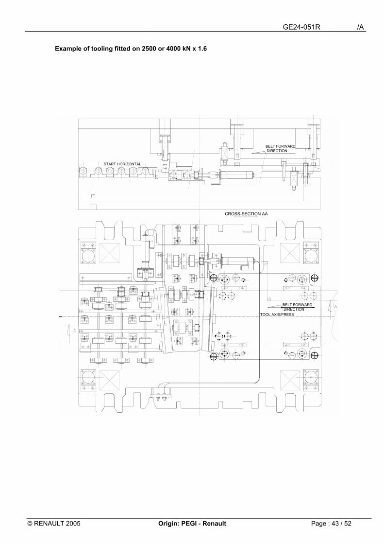
Example of tooling fitted on 2500 or 4000 kN x 1.6
CROSS-SECTION AA
BELT FORWARDDIRECTION
TOOL AXIS/PRESS
BELT FORWARDDIRECTION
BELT FORWARDDIRECTION
START HORIZONTAL
StopStopStopStop
StopStop StopStop
GE24-051R /A
© RENAULT 2005 Origin: PEGI - Renault Page : 44 / 52
6 List of frames and standard shears available in plants
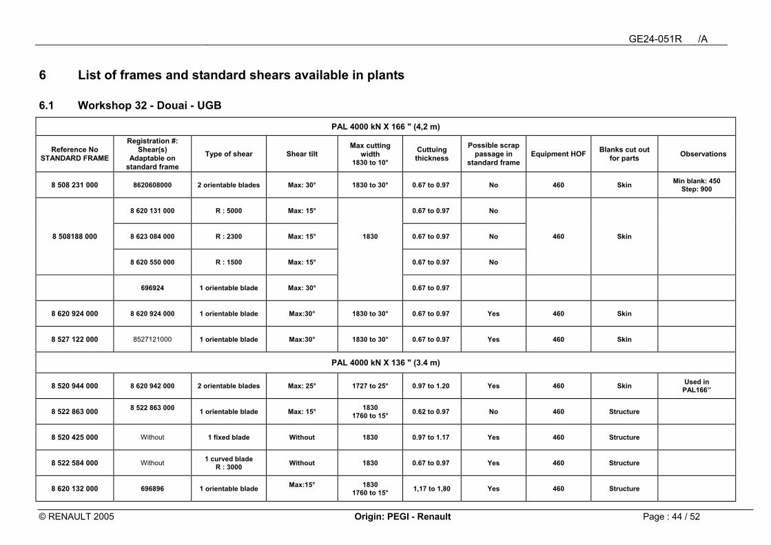
6.1 Workshop 32 - Douai - UGB
PAL 4000 kN X 166 " (4,2 m)
Reference No STANDARD FRAME
Registration #: Shear(s)
Adaptable on standard frame
Type of shear Shear tilt Max cutting
width 1830 to 10°
Cuttuing thickness
Possible scrap passage in
standard frame Equipment HOF Blanks cut out
for parts Observations
8 508 231 000 8620608000 2 orientable blades Max: 30° 1830 to 30° 0.67 to 0.97 No 460 Skin Min blank: 450 Step: 900
8 620 131 000 R : 5000 Max: 15° 0.67 to 0.97 No
8 508188 000 8 623 084 000 R : 2300 Max: 15° 1830 0.67 to 0.97 No 460 Skin
8 620 550 000 R : 1500 Max: 15° 0.67 to 0.97 No
696924 1 orientable blade Max: 30° 0.67 to 0.97
8 620 924 000 8 620 924 000 1 orientable blade Max:30° 1830 to 30° 0.67 to 0.97 Yes 460 Skin
8 527 122 000 8527121000 1 orientable blade Max:30° 1830 to 30° 0.67 to 0.97 Yes 460 Skin
PAL 4000 kN X 136 " (3.4 m)
8 520 944 000 8 620 942 000 2 orientable blades Max: 25° 1727 to 25° 0.97 to 1.20 Yes 460 Skin Used in PAL166��
8 522 863 000 8 522 863 000 1 orientable blade Max: 15° 1830
1760 to 15° 0.62 to 0.97 No 460 Structure
8 520 425 000 Without 1 fixed blade Without 1830 0.97 to 1.17 Yes 460 Structure
8 522 584 000 Without 1 curved blade R : 3000 Without 1830 0.67 to 0.97 Yes 460 Structure
8 620 132 000 696896 1 orientable blade Max:15°
1830 1760 to 15° 1,17 to 1,80 Yes 460 Structure
GE24-051R /A
© RENAULT 2005 Origin: PEGI - Renault Page : 45 / 52
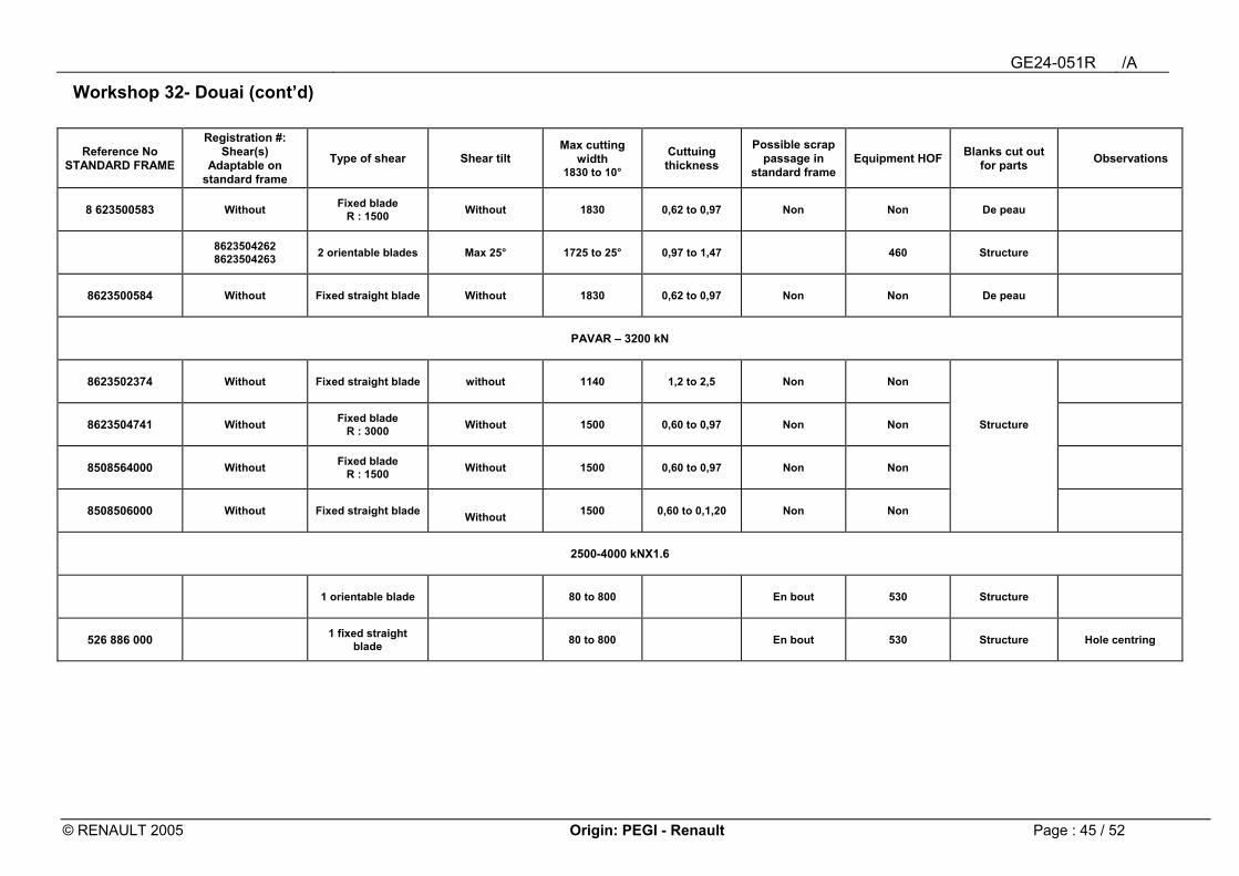
Workshop 32- Douai (cont�d)
Reference No STANDARD FRAME
Registration #: Shear(s)
Adaptable on standard frame
Type of shear Shear tilt Max cutting
width 1830 to 10°
Cuttuing thickness
Possible scrap passage in
standard frame Equipment HOF Blanks cut out
for parts Observations
8 623500583 Without Fixed blade R : 1500 Without 1830 0,62 to 0,97 Non Non De peau
8623504262 8623504263 2 orientable blades Max 25° 1725 to 25° 0,97 to 1,47 460 Structure
8623500584 Without Fixed straight blade Without 1830 0,62 to 0,97 Non Non De peau
PAVAR � 3200 kN
8623502374 Without Fixed straight blade without 1140 1,2 to 2,5 Non Non
8623504741 Without Fixed blade R : 3000 Without 1500 0,60 to 0,97 Non Non Structure
8508564000 Without Fixed blade R : 1500 Without 1500 0,60 to 0,97 Non Non
8508506000 Without Fixed straight blade Without 1500 0,60 to 0,1,20 Non Non
2500-4000 kNX1.6
1 orientable blade 80 to 800 En bout 530 Structure
526 886 000 1 fixed straight blade 80 to 800 En bout 530 Structure Hole centring
GE24-051R /A
© RENAULT 2005 Origin: PEGI - Renault Page : 46 / 52
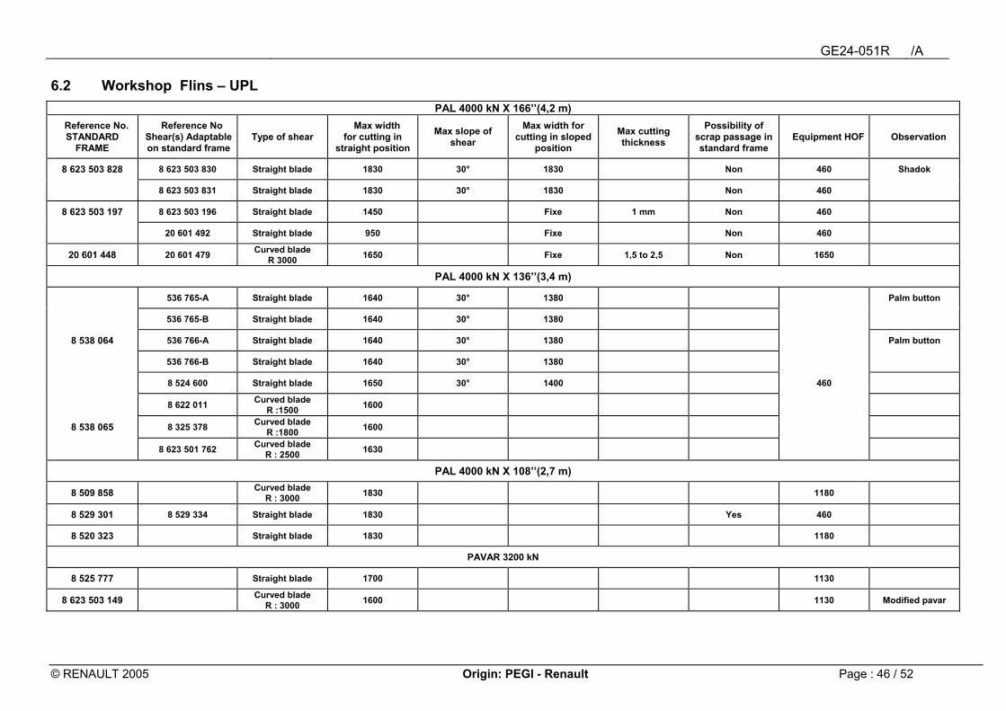
6.2 Workshop Flins � UPL PAL 4000 kN X 166��(4,2 m)
Reference No. STANDARD
FRAME
Reference No Shear(s) Adaptable on standard frame
Type of shear Max width
for cutting in straight position
Max slope of shear
Max width for cutting in sloped
position
Max cutting thickness
Possibility of scrap passage in standard frame
Equipment HOF Observation
8 623 503 828 8 623 503 830 Straight blade 1830 30° 1830 Non 460 Shadok
8 623 503 831 Straight blade 1830 30° 1830 Non 460
8 623 503 197 8 623 503 196 Straight blade 1450 Fixe 1 mm Non 460
20 601 492 Straight blade 950 Fixe Non 460
20 601 448 20 601 479 Curved blade R 3000 1650 Fixe 1,5 to 2,5 Non 1650
PAL 4000 kN X 136��(3,4 m)
536 765-A Straight blade 1640 30° 1380 Palm button
536 765-B Straight blade 1640 30° 1380
8 538 064 536 766-A Straight blade 1640 30° 1380 Palm button
536 766-B Straight blade 1640 30° 1380
8 524 600 Straight blade 1650 30° 1400 460
8 622 011 Curved blade R :1500 1600
8 538 065 8 325 378 Curved blade R :1800 1600
8 623 501 762 Curved blade R : 2500 1630
PAL 4000 kN X 108��(2,7 m)
8 509 858 Curved blade R : 3000 1830 1180
8 529 301 8 529 334 Straight blade 1830 Yes 460
8 520 323 Straight blade 1830 1180
PAVAR 3200 kN
8 525 777 Straight blade 1700 1130
8 623 503 149 Curved blade R : 3000 1600 1130 Modified pavar
GE24-051R /A
© RENAULT 2005 Origin: PEGI - Renault Page : 47 / 52
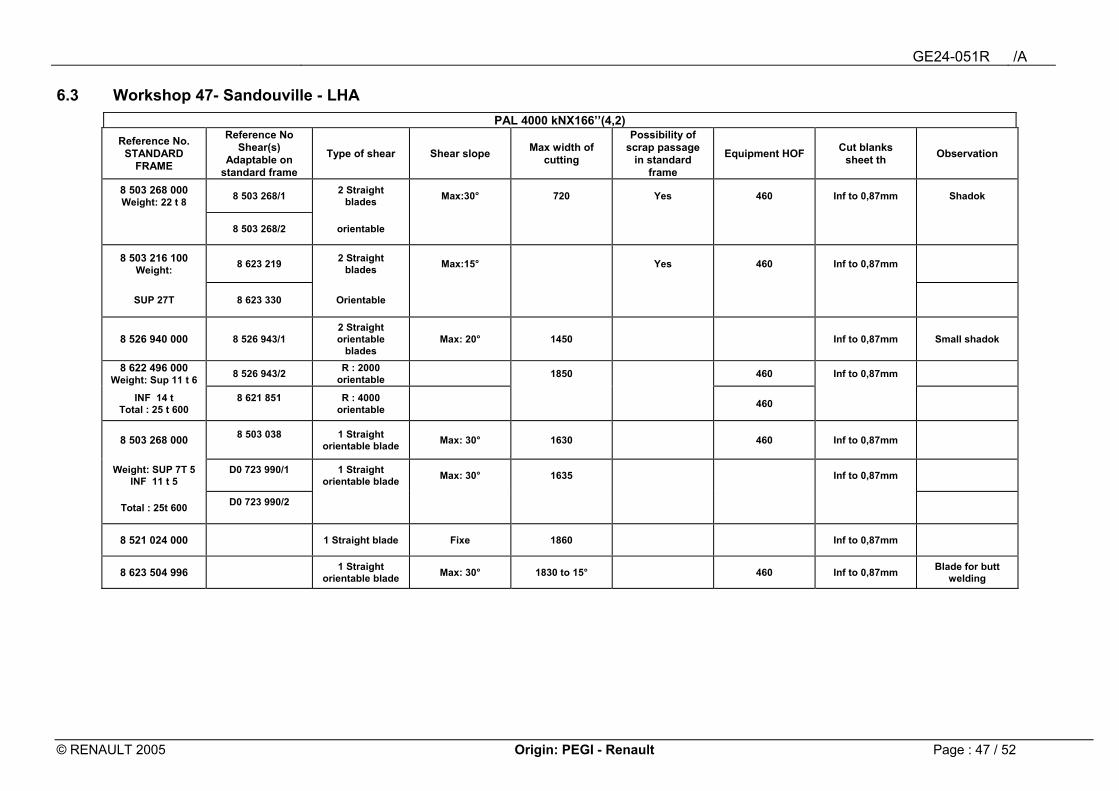
6.3 Workshop 47- Sandouville - LHA PAL 4000 kNX166��(4,2)
Reference No. STANDARD
FRAME
Reference No Shear(s)
Adaptable on standard frame
Type of shear Shear slope Max width of cutting
Possibility of scrap passage
in standard frame
Equipment HOF Cut blanks sheet th Observation
8 503 268 000 Weight: 22 t 8 8 503 268/1 2 Straight
blades Max:30° 720 Yes 460 Inf to 0,87mm Shadok
8 503 268/2 orientable
8 503 216 100 Weight: 8 623 219 2 Straight
blades Max:15° Yes 460 Inf to 0,87mm
SUP 27T 8 623 330 Orientable
8 526 940 000 8 526 943/1 2 Straight orientable
blades Max: 20° 1450 Inf to 0,87mm Small shadok
8 622 496 000 Weight: Sup 11 t 6 8 526 943/2 R : 2000
orientable 1850 460 Inf to 0,87mm
INF 14 t Total : 25 t 600
8 621 851
R : 4000 orientable 460
8 503 268 000 8 503 038
1 Straight orientable blade Max: 30° 1630 460 Inf to 0,87mm
Weight: SUP 7T 5 INF 11 t 5
D0 723 990/1
1 Straight orientable blade Max: 30° 1635 Inf to 0,87mm
Total : 25t 600 D0 723 990/2
8 521 024 000 1 Straight blade Fixe 1860 Inf to 0,87mm
8 623 504 996 1 Straight orientable blade Max: 30° 1830 to 15° 460 Inf to 0,87mm Blade for butt
welding
GE24-051R /A
© RENAULT 2005 Origin: PEGI - Renault Page : 48 / 52
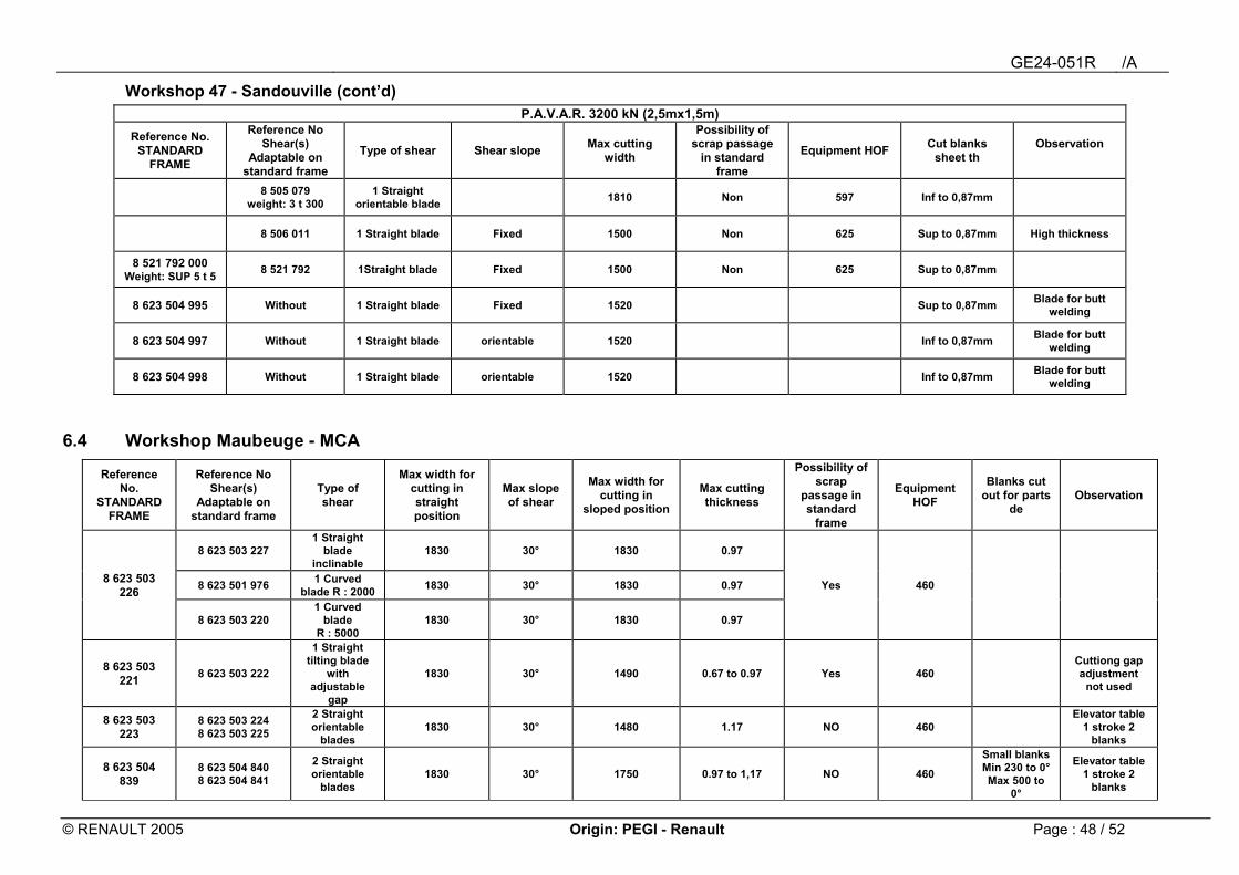
Workshop 47 - Sandouville (cont�d) P.A.V.A.R. 3200 kN (2,5mx1,5m)
Reference No. STANDARD
FRAME
Reference No Shear(s)
Adaptable on standard frame
Type of shear Shear slope Max cutting width
Possibility of scrap passage
in standard frame
Equipment HOF Cut blanks sheet th
Observation
8 505 079 weight: 3 t 300
1 Straight orientable blade 1810 Non 597 Inf to 0,87mm
8 506 011 1 Straight blade Fixed 1500 Non 625 Sup to 0,87mm High thickness
8 521 792 000 Weight: SUP 5 t 5 8 521 792 1Straight blade Fixed 1500 Non 625 Sup to 0,87mm
8 623 504 995 Without 1 Straight blade Fixed 1520 Sup to 0,87mm Blade for butt welding
8 623 504 997 Without 1 Straight blade orientable 1520 Inf to 0,87mm Blade for butt welding
8 623 504 998 Without 1 Straight blade orientable 1520 Inf to 0,87mm Blade for butt welding
6.4 Workshop Maubeuge - MCA
Reference No.
STANDARD FRAME
Reference No Shear(s)
Adaptable on standard frame
Type of shear
Max width for cutting in straight position
Max slope of shear
Max width for cutting in
sloped position
Max cutting thickness
Possibility of scrap
passage in standard
frame
Equipment HOF
Blanks cut out for parts
de Observation
8 623 503 227 1 Straight
blade inclinable
1830 30° 1830 0.97
8 623 503 226 8 623 501 976 1 Curved
blade R : 2000 1830 30° 1830 0.97 Yes 460
8 623 503 220 1 Curved
blade R : 5000
1830 30° 1830 0.97
8 623 503 221 8 623 503 222
1 Straight tilting blade
with adjustable
gap
1830 30° 1490 0.67 to 0.97 Yes 460 Cuttiong gap adjustment
not used
8 623 503 223
8 623 503 224 8 623 503 225
2 Straight orientable
blades 1830 30° 1480 1.17 NO 460
Elevator table 1 stroke 2
blanks
8 623 504 839
8 623 504 840 8 623 504 841
2 Straight orientable
blades 1830 30° 1750 0.97 to 1,17 NO 460
Small blanks Min 230 to 0° Max 500 to
0°
Elevator table 1 stroke 2
blanks
GE24-051R /A
© RENAULT 2005 Origin: PEGI - Renault Page : 49 / 52
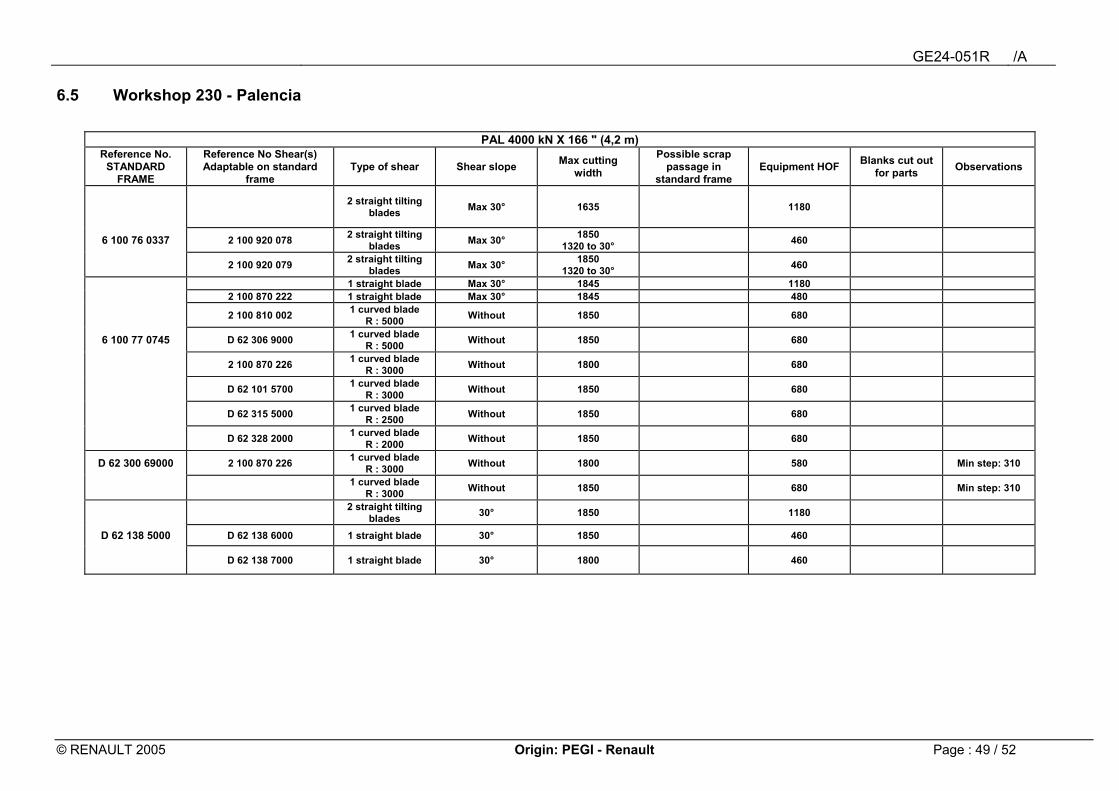
6.5 Workshop 230 - Palencia
PAL 4000 kN X 166 " (4,2 m) Reference No.
STANDARD FRAME
Reference No Shear(s) Adaptable on standard
frame Type of shear Shear slope Max cutting
width
Possible scrap passage in
standard frame Equipment HOF Blanks cut out
for parts Observations
2 straight tilting blades Max 30° 1635 1180
6 100 76 0337 2 100 920 078 2 straight tilting blades Max 30° 1850
1320 to 30° 460
2 100 920 079 2 straight tilting blades Max 30° 1850
1320 to 30° 460
1 straight blade Max 30° 1845 1180 2 100 870 222 1 straight blade Max 30° 1845 480
2 100 810 002 1 curved blade R : 5000 Without 1850 680
6 100 77 0745 D 62 306 9000 1 curved blade R : 5000 Without 1850 680
2 100 870 226 1 curved blade R : 3000 Without 1800 680
D 62 101 5700 1 curved blade R : 3000 Without 1850 680
D 62 315 5000 1 curved blade R : 2500 Without 1850 680
D 62 328 2000 1 curved blade R : 2000 Without 1850 680
D 62 300 69000 2 100 870 226 1 curved blade R : 3000 Without 1800 580 Min step: 310
1 curved blade R : 3000 Without 1850 680 Min step: 310
2 straight tilting blades 30° 1850 1180
D 62 138 5000 D 62 138 6000 1 straight blade 30° 1850 460
D 62 138 7000 1 straight blade 30° 1800 460
GE24-051R /A
© RENAULT 2005 Origin: PEGI - Renault Page : 50 / 52
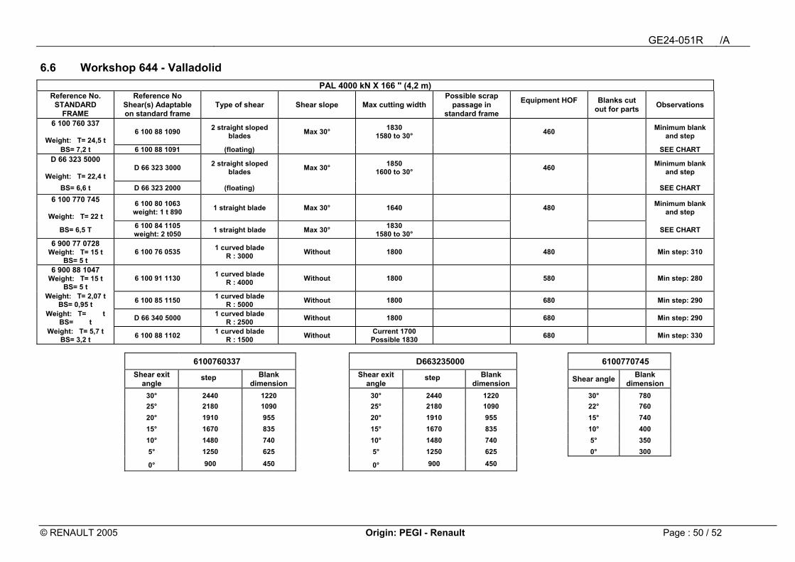
6.6 Workshop 644 - Valladolid PAL 4000 kN X 166 " (4,2 m)
Reference No. STANDARD
FRAME
Reference No Shear(s) Adaptable on standard frame
Type of shear Shear slope Max cutting width Possible scrap
passage in standard frame
Equipment HOF
Blanks cut out for parts Observations
6 100 760 337
Weight: T= 24,5 t 6 100 88 1090 2 straight sloped
blades Max 30° 1830 1580 to 30° 460 Minimum blank
and step
BS= 7,2 t 6 100 88 1091 (floating) SEE CHART D 66 323 5000
Weight: T= 22,4 t
D 66 323 3000 2 straight sloped blades Max 30° 1850
1600 to 30° 460 Minimum blank and step
BS= 6,6 t D 66 323 2000 (floating) SEE CHART 6 100 770 745
Weight: T= 22 t
6 100 80 1063 weight: 1 t 890 1 straight blade Max 30° 1640 480 Minimum blank
and step
BS= 6,5 T 6 100 84 1105 weight: 2 t050 1 straight blade Max 30° 1830
1580 to 30° SEE CHART
6 900 77 0728 Weight: T= 15 t
BS= 5 t 6 100 76 0535 1 curved blade
R : 3000 Without 1800 480 Min step: 310
6 900 88 1047 Weight: T= 15 t
BS= 5 t 6 100 91 1130 1 curved blade
R : 4000 Without 1800 580 Min step: 280
Weight: T= 2,07 t
BS= 0,95 t 6 100 85 1150 1 curved blade R : 5000 Without 1800 680 Min step: 290
Weight: T= t
BS= t D 66 340 5000 1 curved blade R : 2500 Without 1800 680 Min step: 290
Weight: T= 5,7 t
BS= 3,2 t 6 100 88 1102 1 curved blade R : 1500 Without Current 1700
Possible 1830 680 Min step: 330
6100760337 D663235000 6100770745 Shear exit
angle step Blank
dimension Shear exit angle
step Blank dimension Shear angle Blank
dimension 30° 2440 1220 30° 2440 1220 30° 78025° 2180 1090 25° 2180 1090 22° 760 20° 1910 955 20° 1910 955 15° 740 15° 1670 835 15° 1670 835 10° 400 10° 1480 740 10° 1480 740 5° 350 5° 1250 625 5° 1250 625 0° 300
0° 900 450 0° 900 450
GE24-051R /A
© RENAULT 2005 Origin: PEGI - Renault Page : 51 / 52
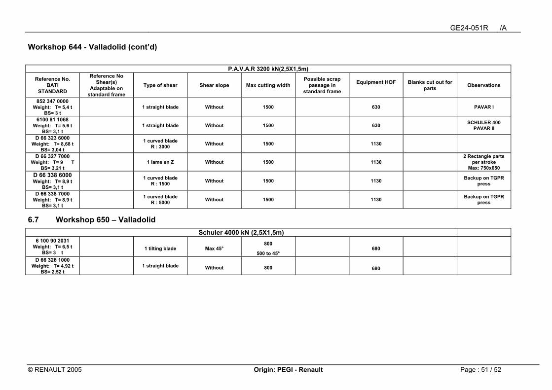
Workshop 644 - Valladolid (cont�d)
P.A.V.A.R 3200 kN(2,5X1,5m) Reference No.
BATI STANDARD
Reference No Shear(s)
Adaptable on standard frame
Type of shear Shear slope Max cutting width Possible scrap
passage in standard frame
Equipment HOF
Blanks cut out for parts Observations
852 347 0000 Weight: T= 5,4 t
BS= 3 t 1 straight blade Without 1500 630 PAVAR I
6100 81 1068 Weight: T= 5,6 t
BS= 3,1 t 1 straight blade Without 1500 630 SCHULER 400
PAVAR II
D 66 323 6000 Weight: T= 8,68 t
BS= 3,04 t 1 curved blade
R : 3000 Without 1500 1130
D 66 327 7000 Weight: T= 9 T
BS= 3,21 t 1 lame en Z Without 1500 1130
2 Rectangle parts per stroke
Max: 750x650 D 66 338 6000 Weight: T= 8,9 t
BS= 3,1 t 1 curved blade
R : 1500 Without 1500 1130 Backup on TGPR press
D 66 338 7000 Weight: T= 8,9 t
BS= 3,1 t 1 curved blade
R : 5000 Without 1500 1130 Backup on TGPR press
6.7 Workshop 650 � Valladolid Schuler 4000 kN (2,5X1,5m)
6 100 90 2031 Weight: T= 6,5 t
BS= 3 t 1 tilting blade Max 45°
800
500 to 45° 680
D 66 326 1000 Weight: T= 4,92 t
BS= 2,52 t 1 straight blade Without 800 680
GE24-051R /A
© RENAULT 2005 Origin: PEGI - Renault Page : 52 / 52
7 List of documents cited NOTE : For non dated documents, the latest version is applicable. EM24.02.030 : Press tooling. Technical drawings. General presentation principles EM24.02.031 : Design rules for the "handling" function of tooling or press tooling elements EM24.02.033 : Press tooling. Evacuation of scrap and collection of wire blanks EM24.03.200 : Technical sheets of cutting and feed presses EM24.03.400 : Butt welder technical sheet EM24.15.100 : Refilling press tooling EM24.54.300 : Compression spring in elastomere � Flexible stripper in elastomere. Spring push-
rods for press tooling. EM24.54.500 : Press tooling: Damper blocks. Dampers. Protection shims. EM24.55.100 : Press tooling. Retaining and locking pins. Retaining/guiding rods with damper. EM24.57.500 : Press tooling. Supporting elements. EM24.59.150 : Pneumatic connecting plates and accessories in press tooling GE24-014R : Press tooling Master drawing for cutting presses GE24-015R : Press tooling Master drawing for progressive tool. GE24-050R : Press tooling. Blank cutting tools for butt welding. Basics on design