Embed Size (px)
Citation preview
PRECEDlNG PAGE BLANK NOT F l u =
WIRE-BLADE DEVELOPMENT FOR
FIXED ABRASIVE SLICING TECHNIQUE (FAST) SLICING*
Chandra P. Khattak, F reder ick Schmid and Maynard B. Smith
C r y s t a l Systems, I n c . 35 Congress S t r e e t , Salem, MA 01970
ABSTRACT
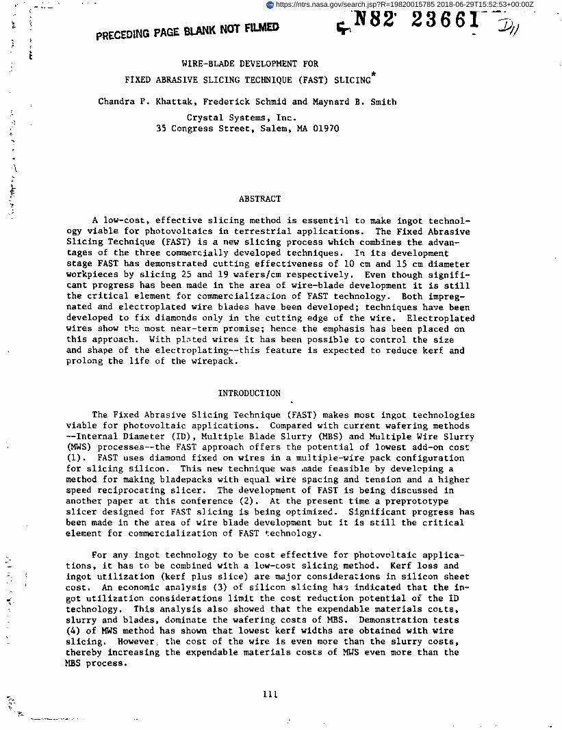
A low-cost, e f f e c t i v e s l i c i n g method is e s s e n t i ~ l t o make ingot technol- ogy v i a b l e f o r pho tovo l ta ics i n t e r r e s t r i a l a p p l i c a t i o n s . The Fixed Abrasive S l i c i n g Technique (FAST) is a new s l i c i n g process which combines t h e advan- t ages of t h e t h r e e commercially developed techniques . I n i ts development s t a g e FAST h a s demonstrated c u t t i n g e f f e c t i v e n e s s of 10 cm and 15 cm diameter workpieces by s l i c i n g 25 and 19 waferslcm r e s p e c t i v e l y . Even though s i g n i f i - can t p rogress has been made i n t h e a r e a of wire-blade development i t i s still t h e c r i t i c a l element f o r commerc ia l i za~ ion of FAST technology. Both impreg- nated and e l e c t r o p l a t e d wire b lades have been developed; techniques have been developed t o f i x diamonds only i n t h e c u t t i n g edge of t h e wire. E l e c t r o p l a t e d wi res show t h z most near-term promise; hence t h e emphasis h a s been placed on t h i s approach. With p l a t e d wi res i t has been p o s s i b l e t o c o n t r o l t h e s i z e and shape of t h e e l e c t r o p l a t i n g - - t h i s f e a t u r e is expected t o reduce ker f and prolong t h e l i f e of t h e wirepack.
INTRODUCTION
The Fixed Abrasive S l i c i n g Technique (FAST) makes most ingo t technologies v i a b l e f o r pho tovo l ta ic a p p l i c a t i o n s . Compared wi th c u r r e n t wafer ing methods - - Internal Diameter (ID), Mul t ip le Blade S l u r r y (MBS) and M u l t i p l e Wire S lu r ry (MWS) processes--the FAST approach o f f e r s t h e p o t e n t i a l of lowest add-on c o s t (1) . FAST uses diamond f ixed on wires i n a mul t ip le-wire pack c o n f i g u r a t i o n f o r s l i c i n g s i l i c o n . Th is new technique was sade f e a s i b l e by develcping a method f o r making bladepacks wi th equa l wi re spacing and t e n s i o n and a h igher speed r e c i p r o c a t i n g s l i c e r . The development of FAST is being d i scussed i n another paper a t t h i s conference ( 2 ) . A t t h e p resen t t ime a prepro to type s l i c e r designed f o r FAST s l i c i n g is being optimized. S i g n i f i c a n t p rogress has been made i n t h e a r e a of wi re blade development but i t is s t i l l t h e c r i t i c a l element f o r commercialization of FAST technology.
For any ingo t technology t o be c o s t e f f e c t i v e f o r pho tovo l ta ic app l ica - t i o n s , i t has t o be combined wi th a low-cost s l i c i n g method. Kerf l o s s and ingot u t i l i z a t i o n (kerf p l u s s l i c e ) a r e major c o n s i d e r a t i o n s i n s i l i c o n shee t c o s t . An economic a n a l y s i s (3) of s i l i c o n s l i c i n g has i n d i c a t e d t h a t t h e in - got u t i l i z a t i o n c o n s i d e r a t i o n s l i m i t t h e c o s t r educ t ion p o t e n t i a l of t h e I D technology. This a n a l y s i s a l s o showed t h a t t h e expendable m a t e r i a l s c o s t s , s l u r r y and b lades , dominate t h e wafer ing c o s t s of MBS. Demonstration tests (4) of MWS method has shown t h a t lowest kerf widths a r e obta ined w i t h wi re s l i c i n g . However, t h e c o s t of t h e wi re is even more than t h e s l u r r y c o s t s , thereby i n c r e a s i n g t h e expendable m a t e r i a l s c o s t s of MUS even more than t h e MBS process .
https://ntrs.nasa.gov/search.jsp?R=19820015785 2018-06-29T15:52:53+00:00Z
I n FAST a pretensioned, fixed-diamond, multiple-wire pack i s r e . i p r o c a t e d s i m i l a r t o t h e MBS process t o s l i c e through t h e workpiece. The multi-wire FAST approach combines t h e econon~ic advantages of I D , MBS and WS techniques . Ex- pendable m a t e r i a l s c o s t s a r e low a s i n I D s l i c i n g , c a p i t a l equipment and l abor c o s t s a r e low a s i n MBS s l i c i n g , and m a t e r i a l u t i l i z a t i o n is high a s i n MWS wafering.
ADVANTAGES AND REQUIREMEM'IS OF FAST WIREPACKS
Aside from t h e economic advantages, t h e r e a r e t e c h n i c a l advantages of us ing multi-wire FAST ap?roach:
(1) Due t o t h e symmetry, w i r e s do no t torque t h e wafers a f t e r s l i c i n g a s i n t h e case of f l a t b lades ; t h i s a l lows f o r less c lea rance and, t h e r e f o r e , reduced ker f width.
(2) I n case of wi re breakage only two wafers c o n t a c t i n g t h a t wi re are l o s t .
(3) The diamonds f i x e d on t h e w i r e prevent wi re wear, hence wi re and a b r a s i v e c o s t i s minimized.
( 4 ) No f a t i g u e problems occur because wi re is n o t wrapped around r o l l e r s .
(5) Wires a r e cheap t c f a b r i c a t e t o a h igher dimensional accuracy and uniformity .
(6) No cor ros ion problems occur s i n c e t t e wi res a r e n i c k e l o r copper p la ted .
(7) Wires can be pre tensioned t o h igher s t r e s s e s .
(8) Wires do not buckle under h igh feed f o r c e s .
(9) S l i c i n g is c a r r i e d out under low feed f o r c e s r e s u l t i n g i n low s u r f a c e damage.
(10) Wafers produced show no edge chipping problems.
The e s s e n t i a l requirements of wirepacks used f o r FAST s l i c i n g a r e :
(1) The w i r e s must be clamped t o prevent s l ippage and must be wi th equal t ens ion and spacing i n t h e bladepack.
(2) Wire core must have high y i e l d s t r e n g t h and modulus f o r minimum d e f l e c r i o n .
(3) Diamonds must be f ixed on wi re wi th high, uniform concen t ra t ion .
(4) Prevent e r o s i o n of t h e mat r ix holding t h e diamonds.
(5) Diamonds must e x h i b i t long l i f e and hlqh c u t t i n g r a t e s .
(6) Wire diameter must be minimum t o reduce k e r f .
(7) Minimized wander f o r a c c u r a t e s l i c i n g .
(8) Prevent cor ros ion between t h e mat r ix ho ld ing t h e diamonds and t h e c o r e m a t e r i a l .
In t h e above t a b u l a t i o n t h e f i r s t requirement i s r e l a t e d t o f a b r i c a t i o n
OR! 2 '>!.!'.K p-,qTF BLACK AN3 l'itil'i'ii I ' ilOTOGWfl
of wirepack and the r e s t r e l a t e t o p r o p e r t i e s of w i r e , ma t r ix and procedures f o r f i x i n g Jiamonds on to wi res . Simple f a b r i c a t i o n procedures have been de- veloped which g ive t h e w i r e s equa l spacing and t e n s i o n w i t h no problen; of cumulative e r r o r s . A f t e r e v a l u a t i o n of v a r i o u s c o r e m a t e r i a l s (5) a s e l e c t i o n was made t o use high s t r e n g t h steel, s t a i n l e s s steel and tungsten. High s t r e n g t h s t e e l and s t a i n l e s s s t e e l w i r e s w e r e s e l e c t e d based on high y i e l d s t r e n g t h and tungs ten on t h e b a s i s of i ts high modulus. Most of t h e work w a s c a r r i e d ou t wi th a 5 m i l (0.125 mm) tungsten w i r e because of i t s h igh modulus and c o r r o s i o n r e s i s t a n c e .
Two approaches were pursued i n f i x i n g diamonds, v i z . impregnated wi res and e l e c t r o p l a t e d wires . I n t h e former case diamonds were impregnated i n t o a s o f t copper shea th on t h e core w i r e , whereas i n t h e l a t t e r c s s e diamonds were f ixed by e l e c t r o p l a t i n g .
IMPREGNATED WIRES
Commercially a v a i l a b l e impregnated wi re (6) was 5 m i l (0.125 mm) s t a i n - l e s s s t e e l co re wi th a 1 . 5 m i l (37.5 um) copper s h e a t h impregnated w i t h 45 pm n a t u r a l diamonds. S l i c i n g wi th t h i s w i r s showed t h a t c u t t i n g e f f e c t i v e n e s s was l o s t wi th in approximately 0.25 inch depth of c u t . Examination of t h e wi res showed cons ide rab le diamond pul l -out . E l e c t r o l e s s n i c k e l p l a t i n g of these wi res reduced t h e diamond pu l l -ou t considerably . I t was found t h a t n i c k e l p l a t i n g t h i c k n e s s of 0.3 m i ; (7.5 um) produced b e s t r e s u l t s ; a n i c k e l l a y e r of 12.5 u m was s u f f i c i e n t t o bury t h e diamoncs. A wafer ing experiment of a 10 cm diameter s i l i c o n workpiece w i t h 114 p a r a l l e l b i l e s spaced a t 191cm wi th these wi res showed an average s l i c i n g r a t e of 2.33 milslmin (0.059 mmlmin) and prodrlced a 96.5% y i e l d .
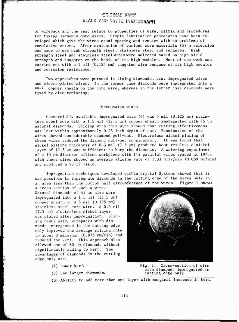
Impregnation techniques developed w i t h i n C r y s t a l Systems showed t h a t it was p o s s i b l e t o impregnate diamonds i n t h e c u t t i n g edge of t h e wi res only i n an a r e a l e s s than i h e bottom h a l f circumference of t h e wi res . F igure 1 shows a c r o s s s e c t i o n of such a wire . Natura l diamonds of 45 u m s i z e were impregnated i n t o a 1.5 m i l (37.5 pm) copper shea th on a 5 m i l (0.125 mm) s t a i n l e s s s t e e l co re wire . A 0.3 m i l (7.5 um) e l e c t r o l e s s n i c k e l l a g e r was p la ted a f t e r impregnation. S l i c - i c g t e s t s us ing wirepacks wi th d ia - monds impregnated i n t h e c u t t i n g edge only improved t h e average s l i c i n g r a t e t o about 3 mils/min (0.075 mm/min) and reduced the Xerf. Th i s approach a l s o allowed use of 60 pm diamonds without s i g n i f i c a n t l y adding t o k e r f . The advantages of diamonds i n t h e c u t t i n g edge only a r e :
(1) Lower kerf . Fig. 1. Cross-sect ion of wi re wi th diamonds impregnated i n
(2) Use l a r g e r diamonds. c u t t i n g edge only
(3) A b i l i t y t o add more than one l a y e r wi th marginal i n c r e a s e i n kerf.
(4) Minimize degradation of guide r o l l e r s i n t h e FAST s l i c e r .
(5) Better sea t ing of t he wires i n t h e grooved guide r o l l e r s .
(6) Improved accuracy of s l i c i n g because of absence of diamonds on t h e s ides of t he wires.
(7) Minimize wire wander when diamonds i n t he c u t t i n g edge are some- what "du: led".
Even though s ign i f i can t progress has been made wi th impregnated wires considerable e f f o r t has t o be devoted towards achieving high concentrat ion of diamonds with good uniformity and preventing diamond pull-out during s l i c i n g . f
ELECTROPLATED WIRES
A t the s t a r t of t h i s program e l ec t rop l a t ed wi res were not commercially ava i lab le . I n i t i a l work was ca r r i ed out i n cooperation with var ious p l a t i n g vendors.
Choice of Core Wire
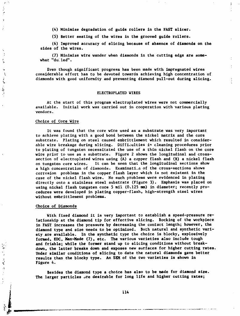
It was found tha t the core wire used a s a s u b s t r a t e was very important t o achieve p l a t i n g with a good bond between the n i cke l matr ix and the core subs t ra te . P l a t i ng on steel caused embrittlement which resu l ted i n consider- ab le wire breakage during s l i c i n g . D i f f i c u l t i e s i n c lean ing procedures p r i o r t o p l a t i n g of tungsten necess i ta ted t he use of a t h i n n icke l f l a s h on the co re wire p r i o r t o use a s a subs t ra te . Figure 2 shows the longi tud ina l and cross- sec t ion of e lec t rop la ted wi res using (A) a copper f l a s h and (B) a n i cke l f l a s h on tungsten core wires. It can be seen t h a t the longi tud ina l s ec t i ons show a high concentrat ion of diamonds. Examina t i ,~ of t h e cross-sect ions shows corrosion problems i n the copper f l a s h l aye r which is not e x i s t e n t i n t he case of the n icke l f l a s h wire. No such problems were evidenced i n p l a t i n g d i r e c t l y onto a s t a i n l e s s steel subs t r a t e (Figure 3). Emphasis was placed on using n icke l f l a s h tungsten core 5 m i l (0.125 mu) i n diameter; recent ly pro- cedures were developed i n p l a t i n g copper-flash, high-strength steel wires without embrittlement problems.
Choice of Diamonds
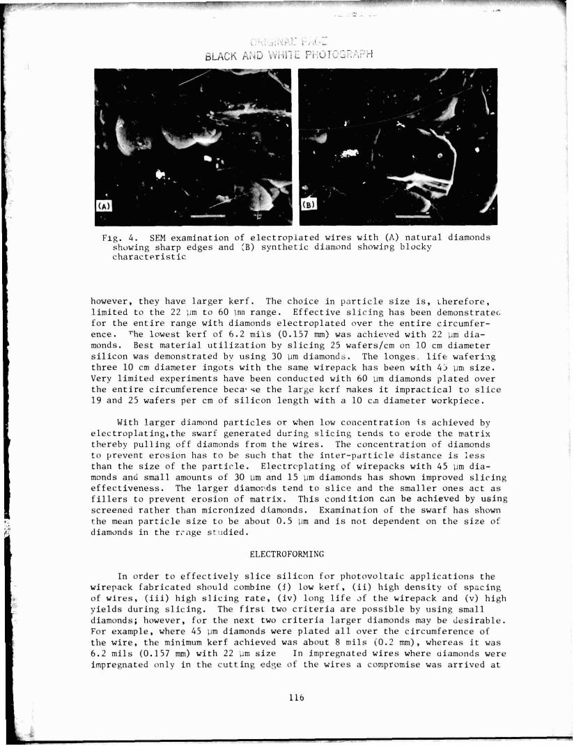
With f ixed diamond it is very important t o e s t a b l i s h a speed-pressure re- l a t i onsh ip a t t h e diamond t i p f o r e f f e c t i v e s l i c ing . Rocking of t h e workpiece in FAST increases the pressure by decreasing the contac t length; however, t he diamond type and s i z e needs t o be optimized. Both n a t u r a l and syn the t i c var i - e t y a r e ava i lab le . I n t he syn the t i c type the choice is blocky, explosively formed, EDC, Xan-Hade (7) , etc. The var ious v a r i e t i e s a l s o include tough and f r i a b l e ; while t he former s tand up t o s l i c i n g condi t ions without break- down, t he l a t t e r breaks down and exposes new su r f aces f o r higher c u t t i n g rates. Under s imi l a r condi t ions of s l i c i n g t o d a t e t he n a t u r a l diamonds gave b e t t e r r e s u l t s than the blocky type. An SEM of t he two v a r i e t i e s is shown i n Figure 4.
Besides the diamond type a choice has a l s o t o be made f o r diamond s i z e . The l a rge r p a r t i c l e s re des i r ab l e f o r long l i f e and higher c u t t i n g r a t e s ;
', . -- ,. ...,' . I , *>:t . - , , 3' .-
SLACK A;ia ' ,$ ; , ] - I ? i . : ~ r ~ ~ ~ ~ ; , ~ . , ? ' ~
Fig . 4 . SEM examination of e l e c t r o p l a t e d wi res wi th (A) n a t u r a l diamonds showing sharp edges and {B) s y n t h e t i c diamond showing blocky c h a r a c t e r i s t i c
however, they have l a r g e r k e r f . The choice i n p a r t i c l e s i z e is , heref fore, l i m i t e d t o t h e 22 pm t o 60 urn range. E f f e c t i v e s l i c i n g h a s been demonstrate6 f o r the e n t i r e range wi th diamonds e l e c t r o p l a t e d over t h e e n t i r e c i rcumfer- ence. 'he lowest ke r f of 6 . 2 m i i s (0.157 mm) was achieved wi th 22 pm d ia - monds. Best m a t e r i a l u t i l i z a t i o n by s l i c i n g 25 waferslcm on 10 cm diameter s i l i c o n was demonstrated bv u s i n g 30 urn diamonds. The longes . l i f e w a f e r i ~ g t h r e e 10 cm d i a n e t e r i n g o t s wi th t h e same wirepack h a s been wi th 45 pm s i z e . Very l i m i t e d experiments have been conducted wi th 60 u m diamonds p l a t e d over t h e e n t i r e circumference becaqse t h e l a r g e ke r f makes i t imprac t i ca l t o s l i c e 19 and 25 wafers per cm of s i l i c o n l e n g t h wi th a 10 can diameter workpiece.
With l a r g e r diamond p a r t i c l e s o r when low c o n c e n t r a t i o n is achieved by e l e c t r o p l a t i n g , t h e swarf generated dur ing s l i c i n g t ends t o e rode t h e mat r ix thereby p u l l i n g off diamonds from t h e wires . The concen t ra t ion of diamonds t o prevent e ros ion has t o b~ such t h a t the i n t e r - p a r t i c l e d i s t a n c e i s l e s s than t h e s i z e of t h e p a r t i c l e . E l e c t r c p l o t i n g of wirepacks wi th 45 pm d i a - monds anti smal l amounts of 30 um and 1 5 pm diamonds h a s shown improved s l i c i n g e f f e c t i v e n e s s . The l a r g e r diamo~lds tend t o s l i c e and the smal le r ones a c t a s f i l l e r s t o prevent e ros ion of ma t r ix . Th i s c o n d i t i o n can be achieved by us ing screened r a t h e r than micronized dtamonds. Examination of t h e swarf h a s shown the mean p a r t i c l e s i z e t o be about 0.5 Dm and is no t dependent on t h e s i z e of diamonds i n t h e r rnge s t ~ t d i e d .
ELECTROFORMING
I n o rde r t o e f f e c t i v e l y s l i c e s i l i c o n f o r pho tovo l t a ic a p p l i c a t i o n s the wirepack f a b r i c a t e d should combine ( I ) low k e r f , ( i i ) high d e n s i t y of spac ing of w i r e s , ( i i i ) high s l i c i n g r a t e , ( i v ) long l i f e ~f t h e wirepack and (v) h igh y i e l d s dur ing s l i c i n g . The f i r s t two c r i t e r i a a r e p o s s i b l e by us ing small diamonds; however, f o r the next two c r i t e r i a l a r g e r diamonds may be d e s i r a b l e . For example, where 45 pm diamonds were p l a t e d a l l over t h e c i rcumference of t h e w i r e , t h e minimum kerf achieved was about 8 m i l s (0.2 mm), whereas i t was 6 . 2 m i l s (0.157 mm) with 22 u m s i z e In impregnated w i r e s where aiamonds were impregnated only i n t h e c u t t i n g edge of t h e w i r e s a compromise was a r r i v e d a t
where l a r g e r diamonds could be used wi thou t s i g n i f i c a n t i n c r e a s e i n k e r f . Techniques were developed where diamonds were e l e c t r o p l a t e d i n t h e c u t t i r ; edge clnly and , t h e r e f o r e , b e n e f i t s could be d e r i v e d by u s i n g l a r g e r diamonds and m a i n t a i n i n s a low k e r f .
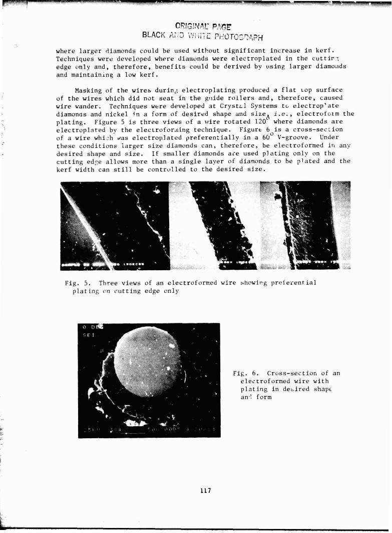
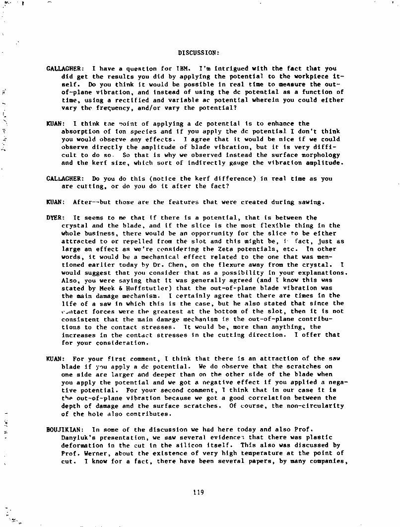
Masking of t h e w i r e s d u r i n s e l e c t r o p l a t i n g produced a f l a t LOP s u r f a c e of t h e w i r e s which d i d no t s e a t i n t h e g r ~ i d e r o l l e r s and , t h e r e f o r e , caused w i r e wander. Techniques were developed a t C r y s t t l Systems t~ e l e c t r o p ' a t e diamonds and n i c k e l ;n a form of d e s i r e d shape and s i z e h i.e., e l e c t r o f o ~ m t h e p l a t i n g . F i g u r e 5 is t h r e e v iews o f a w i r e r o t a t e d 120 where diamonds a r e e l e c t r o p l a t e d by t h e e l e c t r o f o r , n i n g technique . F igu re 6 is a c r o s s - s e c t i o n of a w i r e whi:h g a s e l e c t r o p l a t e d p r e f e r e n t i a l l y i n a 6 0 O V-groove. Under t h e s e c o n d i t i o n s l a r g e r s i z e diamonds can , t h e r e f o r e , be e l ec t ro fo rmed i n any d e s i r e d shape and s i z e . I f s m a l l e r diamonds a c e used p l a t i n g o n l y on t h e c u t t i n g e d ~ e a l l o w s more than a s i n g l e l a y e r of diamonds t o be p l a t e d and t h e k e r f width can s t i l l be c o n t r o l l e d t o t h e d e s i r e d s i z e .
F ig . 5. Three views of an e l ec t ro fo rmed w i r e showicg prefei-ent . ia1 p l a t i n g cn c u t t i n g edge on ly
Fig . 6. e l e c t p l a t 3 an.! f
C ross - sec t ion o f an .reformed w i r e w i t h .ng i n d e s i r e d shapc orm

RESULTS
The feasibility of using FAST for photovoltaic applications has been dem- onstrated. kire-blade development has been found to be critical to coamercial- ization of FAST. Control of the diamond plating on wires has shown effective slicing of 10 cm diameter silicon ingots at 25 waferslcm with 224 wires in a wirepack at an average slicing rate of 3.03 milslmin (0.077 mm/min), and over 99% yield (2 ) . It has been shown that the slicing rate is a strong function of the reciprocating speed of the bladehead; average cutting rates of 5.7 mils/ min (0.145 mmlmin) have been demonstrated. Wirepack life of wafering three 10 cm diameter silicon ingots has been shown. Effectiv; slicing of 10 cm x 10 cm and 15 cm diameter crors-section ingots has also been carried out.
Electroforming techr~iques 'lave been demonstrated on individual ; ;es. Tooling for performing these tests on wirepacks has recently been received in- house; it is expected that this approach will increase the life of the wire- pack considerably as well as optimize other slicing parameters.
* Supported in part by the LSA Project, JPL, sponsored by DOE through agreement with NASA.
REFERENCES
1. H, Coldman and M. Wolf, DOE/JPL 954796, Quarterly Report, November 1978.
2. F. Schmid. M. B. Smith, and C. P. Khattak, Proc. JPLILSA Project Wafering Workshop, Phoenix, AZ, June 1981, to be published.
3. K. W. Koliwad, M. H. Leipolc!, G. D, Cum-ng and T, 6. Digges, Jr., Proc. 12th IEEE Photovoltaic Specialists Conf., Baton Rouge, LA (1976).
4 . C. P . Chen, "Multi-Wire Slurry Wafering Demonstrations," DOEIJPL Publ. 78-37, February 22, 1978.
5. F. Schmid and C. P. Khattak, ERDAIJPL 954373, Final Report (Phase I), December 1977.
6. Laser Technology, Inc., No. Hollywood, CA.
7. EDC and Man-Made are trademarks of DeBeers and General Electric Company, respectively.
DISCUSSION:
GALLAGHER: I have a question for IBM. I'm intrigued with the fact that you did get the results you did by applying the potential to the workpiece it- self. Do you think it would be possible in real time to measure the out- of-plane vibration, and instead of using the dc potential as a function of time, using a rectified and variable ac potential wherein you could either vary the frequency, and/or vary the potential?
KUAN: I think tae xint of applying a dc potential is to enhance the absorption of ion species and if you apply the dc potential I don't think you would observe any effects. I agree that it would be nice if we could observe directly the amplitude of blade vibration, but it is very diffi- cult to do so- So that is why we observed instead the surface morphology and the kerf size, which sort of indirectly gsuge the vibration amplitude.
GALLAGHER: Do you do this (notice the kerf difference) in real time as you are cutting, or do you do it after the fact?
KUAN: After--but those are the features that were created during sawing.
DYER: It seems to me that If there is a potential, that is between the crystal and the blade, and if the slice is the most flexible thing in the whole business, there would be an opportunity for the slice to be either attracted to or repelled from the slot and this might be, i . fact, just as large an effect as we're ccnsidering the Zeta potentials, etc. In other words, it would be a mechanical effect related to the one that was men- tioned earlier today hy Dr. Chen, on the flexure away from the crystal. I would suggest that you consider that as a possibility in your explanations. Also, you were saying that it was generally agreed (and I know this was stated by Meek & Huffstutler) that the out-of--plane blade vibration was the main damage mechanism. I certainly agree that there are times in the life of a saw in which this is the case, but he also stated that since the t.>atact forces were the greatest at the bottom of the slot, then it is not consistent that the main dam~ge mechanism is the out-of-plane contribu- tions to the contact stresses. It would be, more than anything, the increases in the contact stresses in the cutting direction. I offer that for your consideration.
KUAN: For your first comment, I think that there is an attraction of the saw blade if yqu apply a dc potential. We do observe that the scratches on one side are larger and deeper than on the other side of the blade when you apply the potential and we got a negative effect if you applied s nega- tive potential. For your second comment, I think that Cn our case it is t%e out-of-plane vibration because we got a good correlation between the depth of damage and the surface scratches. Of course, the non-circularity of the hole also contributes.
BOUJIKIAN: In some of the discussion we had here today and also Prof. Danyluk's presentation, we saw several evidence; that there was plastic deformation in the cut in the silicon itself. This also was discussed by Prof. Werner, about the existence of very high temperature at the point of cut. I know for a fact, there have been several papers, by many companies,
on theraw1 damage. It is f a l c that General Electric people brauuht up thermal damage in the cut. b .11, In uy opinion, is much more severe than the vibration damage. 1 have been in the abrasive diamond-blade-busincse for 20 to 22 years. I would like to make a statement that General Elec- tric really saved this dlaaosd-abrasive industry by developing the indus- trinl diamond. It was one of the teai discoveries of the century if not the only one as far as the diamond-blade industry is concerned. However, thcrc have been several studies (including General Electric, at their facilities over in Auburn years ago, through the direction of Tueio and Ernie Rnderman, etc.) that without any question there is a definite hresk- down at high temperature wfth ~ynthetic diamond compared to the natural diamond. In your speech, you referred to heat-treating it at llOO°C. You used the word "controlled." If you take your dtamond and put it in even 1100°~ in open sir for half an hour you will end up with a hunch of hlack junk. I don't want to make the assumption that the CE diamond is actually. in terms of toughness, hardness and structure, superior to nat- ural diamond. The only main factor is in ID slicing because temperature 1s more of a fsctor than anything else in that particular applicatian. You did not address nqwhere in your speech a comparisoii ulth the natural diamond in ID slicing. T would like to know why.
FALLON: To clarify a number of the points that were brought up: llOO°C Is a test that we conduct to determine the thermal toughness index. It's one that we have heen doing for years and we don't seem to reduce our diamonds to little hlack stubs hy doing i t to llOO°C. As regards the temperature hreakdown, all 1 can do is again go back to the fact, mentioned earlier today, that bonding systems break dawn at 700°c, so if you have e dl~mond that can withstand 5000°C it doesn't really matter, t f your bond is going to go at 700° anywav. We made no comparison, or try not to refer to any comparison with mined diamonds because depending upon test condi- tions, mined diamonds will be better than man-made diamonds, or men-made will be better than mined: they will be equivalent. The important point is the fact that man-made diamond is consistent. You will get the same dtamond today thet you get two years from now. This is not true wfth mined diamnds.
WERNER: Ftrst, I think you are absolutely right thet the hfg advantage of man-made diamonds is that tLe characteristics and the properties are much more consistent. On the other side, especially tn ID sawing, so far the natural diamond is preferred to the synthetic one. I would like you to comment a little more on what General Electric !s doing at the moment to lift th2 synthetic material to the same performance level as the natural one. Second, a comment: the heat flows through the tip of the diamond and then is distributed in the milch greater volume of the diamond. Therefore, the trans!tton temperature from the diamond into the bond is several hun- dred degrees lower and the nickel layer never gets a temperature up to 700'. The maximum temperature that I would expect to occur In the nickel layer is maybe 150-200~, so your argument that the nickel fails before the dtamond fails is completely wrong. Another misconception is the air cushion you referred to in the circumferential vicinity of the wheel. That cushion does not really exist. There are a few atoms going around with the wheel but the mass of this layer of air is much too small to prevent a fluid from getting into contact with the wheel. The real effect
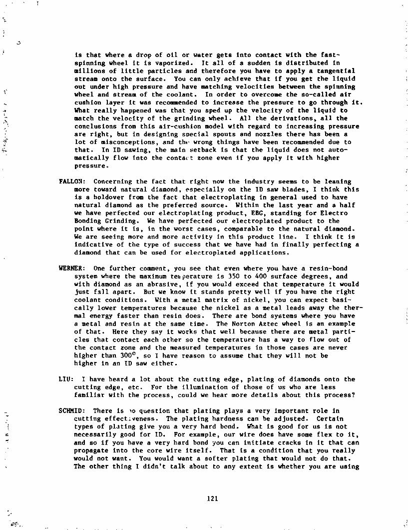
is t h a t where a drop of o i l o r water g e t s i n t o c o n t a c t w i t h t h e f a s t - sp inn ing wheel i t i s vaporized. I t a l l of a sudden is d i s t r i b u t e d i n m i l l i o n s of l i t t l e p a r t i c l e s and t h e r e f o r e you have t o a p p l y a t a n g e n t i a l stream onto t h e su r face . You can on ly ach5eve t h a t i f you g e t t h e l i q u i d o u t under h igh p ressure and have matching v e l o c i t i e s between t h e s p i n n i n g wheel and stream of the coo lan t . I n o r d e r t o overcome t h e so-cal led air cushion l a y e r i t was recommended t o i n c r e a s e t h e p r e s s u r e t o go through i t . What r e a l l y happened was t h a t you sped up t h e v e l o c i t y of t h e l i q u i d t o match t h e v e l o c i t y of t h e g r i n d i n g wheel. A l l t h e d e r i v a t i o n s , a l l t h e conc lus ions from t h i s a i r -cush ion model w i t h regard t o i n c r e a s i n g p r e s s u r e a r e r i g h t , but i n des ign ing s p e c i a l s p o u t s and nozz les t h e r e h a s been a l o t of misconcept ions , and tht. wrong t h i n g s have been recommended due t o t h a t . I n I D sawing, t h e main se tback is t h a t t h e l i q u i d does not auto- m a t i c a l l y f low i n t o the c o n t a c t zone even i f you app ly I t w i t h h igher p ressure .
FALLON: Concerning t h e f a c t t h a t r i g h t now t h e I n d u s t r y seems t o be l e a n i n g more toward n a t u r a l diamond, e s p e c i a l l y on the I D saw b lades , I t h i n k t h i s is a holdover from t h e f a c t t h a t e l e c t r o p l a t i n g i n g e n e r a l used t o have n a t u r a l diamond a s the p r e f e r r e d source . Within t h e l a s t yea r and a h a l f we have pe r fec ted our e l e c t r o p l a t i n g product , EBG, s t a c d i n g f o r E l e c t r o Bonding C r i n d i ng. We have pe r fec ted our e l e c t r o p l a t e d product t o t h e p o i n t where it is, i n t h e wors t c a s e s , comparable t o t h e n a t u r a l diamond. We a r e s e e i n g more and more a c t i v i t y i n t h i s product l i n e . I t h i n k i t is i n d i c a t i v e of t h e type of success t h a t we have had i n f i n a l l y p e r f e c t i n g a diamond t h a t can be used f o r e l e c t r o p l a t e d a p p l i c a t i o n s .
WERNER: One f u r t h e r comment, you s e e t h a t even where you have a resin-bond system where the maximum t e l ~ p e r a t u r e is 350 t o 400 s u r f a c e degrees , and w i t h diamond a s an a b r a s i v e , i f you would exceed t h a t temperature i t would j u s t f a l l a p a r t . But w e know I t s t a n d s p r e t t y w e l l i f you have t h e r i g h t c o o l a n t cond i t ions . With a meta l ma t r ix of n i c k e l , you can expect bas i - c a l l y lower temperatures because t h e n i c k e l a s a meta l l e a d s away the t h e r - mal energy f a s t e r than r e s i n does. There a r e bond systems where you have a metal and r e s i n a t the same time. The Norton Aztec wheel is an example of t h a t . Here they say i t works t h a t w e l l because t h e r e a r e meta l p a r t i - c l e s t h a t c o n t a c t each o t h e r s o t h e temperature has a way t o flow o u t of t h e c o n t a c t zone and the measured temperatures i n those c a s e s a r e never h igher than 300°, s o I have reason t o assume t h a t they w i l l no t be h igher i n a n I D saw e i t h e r .
LIU: I have heard a l o t about the c u t t i n g edge, p l a t i n g of diamonds on to t h e c u t t i n g edge, e t c . For the i l l u m i n a t i o n of those of u s who a r e less f a m i l i a r wi th t h e p rocess , could we h e a r more d e t a i l s about t h i s p rocess?
SCHMID: There is !o q u e s t i o n t h a t p l a t i n g p l a y s a very important r o l e i n c u t t i n g e f f e c t ~ v e n e s s . The p l a t i n g ha rdness can be a d j u s t e d . C e r t a i n types of p l a t i n g g i v e you a very hard bend. What is good f o r u s is n o t n e c e s s a r i l y good f o r I D . For example, o u r w i r e does have some f l e x t o i t , and s o i f you have a very hard bond you can i n i t i a t e c r a c k s i n i t t h a t can propagate i n t o the c o r e wire i t s e l f . That is a c o n d i t i o n t h a t you r e a l l y would no t want. You would want a s o f t e r p l a t i n g t h a t would n o t do t h a t . The o t h e r t h i n g I d i d n ' t t a l k about t o any e x t e n t is whether you a r e u s i n g
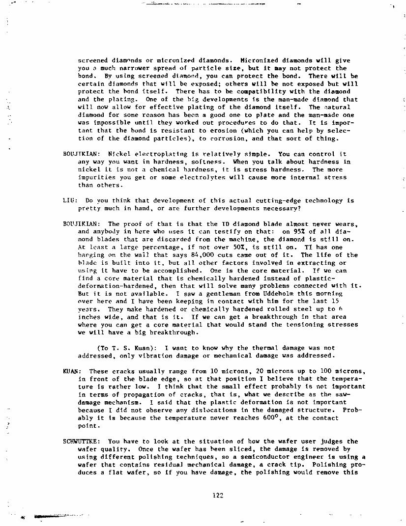
screened diamnnds or micronized diamonds. Micronized diamands will give you a much narrower spread of particle size, but it may not protect the bond. By using screened diamoad, you can protect the bond. There will be certain diamonds that will be exposed; others will he not exposed but will protect the bond itself. There has to be compatibility with the diamond and the plating. One of the h tg developments is the man-made diamond that will now allow for effective plating of the diamond itself. The aatural diamond for some reason has been a good one to plate and the man-made one was impossible until they worked out procedures to do that. It is impor- tant that the bond is resistant to erosion (which you can help by selec- tion of the diamond particles), to corrosion, and that sort of thing.
BOUJTRIAN: Nickel electroplating is relatively simple. You can control it any way you want in hardness, softness. When you talk about hardness in nickel it is not a chemical hardness, it is stress hardness. The more impurities you get or some electrolytes will cause more internal stress than others.
LIU: Do vou think that development of this actual cutting-edge technology is pretty much in hand, or are further developments necessary?
BOUJIKIAN: The proof of that is that the ID diamond blade almost never wears, and anybody in here who uses it can testify on that: on 95% of all dia- mond blades that are discarded from the machine, the diamond is stfll on. At least a large percentage, if not over 50%. is still on. TI has one harging on the wall that says 84,000 cuts came out of it. The life of the blade is built into it. hut all other factors involved in extracting or u s i ~ g it have to be accomplished. One is the core material. If we can find a core material that is chemically hardened instead of plastic- deformation-hardened, then that will solve many problems connected with it. But it is not avajlable. I saw a gentleman from Uddeholm this morning aver here and I have been keeping in contact with him for the last 15 years. They make hardened or chemically hardened rolled steel up to 6 inches wide, and that is it. If we can get a breakthrough in that area where you can get a core material that would stand the tensioning stresses we will have a big breakthrough.
(To T. S. Kuan): I want to know why the thermal damage was not addressed, only vibration damage or mechanical damage was addressed.
KUAN: These cracks usually range from 10 microns, 20 microns up to 100 microns, in front of the blade edge, so at that position I believe that the tempera- ture is rather low. I think that the small effect probably is not important in terms of propagation of cracks, that is, what we describe as the saw- damage mechanism. I said that the plastic deformation is not important because I did not observe any dislocations in the damaged structure. Prob- ably it is because the temperature never reaches 600'. at the contact point.
SCHWUTTKE: You have to look at the situation of how the wafer user judges the wafer quality. Once the wafer has been sliced, the damage is removed by using different polishing techniques, so a semiconductor engineer is using a wafer that contains residual mechanical damage, a crack tip. Polishing pro- duces a flat wafer, so if you have damage, the polishing would remove this
anyhow. We are much mcre concerned that a wafer contains residual damage. This is what is killing the semiconductor wafer.
KOLIWAD: My question is to Drs. Danyluk and Kuan, on the Zeta potential variations with respect to using different chemical environments. The Zeta potential variation and the softening observed in cutting has actually been documented for ceramic cutting--aluminum oxide, for example, where there is beautiful work. When you are cutting, the wafer surfaces are really not virgin silicon any more. I don't have any knowledge of any studies done on Zeta potential on real silicon surfaces. I wonder whether you are influencing the potential of oxide formation and softening the oxide instead, if in fact there is an oxide, and you are affecting the absorption of ionic species on an oxide, or whether it would be better if you add some oxidizing agents to your solution in addition to whatever lubricants or temperature environments you are using?
DANYLUK: First, I would like to say I don't believe the Zeta potential measurements have much to do with the mechanisms that we are talking about. Most of the Zeta potential measurements are done on crushed silicon. My opinion is that the crushing process itself affects the Zeta potential measurement that is used in a description of the space charges. These space charges, which are essentially what Dr. Kuan is talking about and which I am implying exist at surfaces, essentially exist at surfaces that start out being electrically charged. For example, dislocation cores are electrically charged but the overall surface is electrically neutral. The problem then comes in as to what the space-charge region has to do with the cutting phenomena. I believe that it has got to do with the Dehye- Huckle length of the space-charge region. If it is big, then it has one affect and if it is small, it has another affect.
KUAN: There are basically two theories to interpret the lubricant effects. One is the Rebfnder effect and one is the Westwood mechanism. I person- ally believe tnat the Westwood mechanism is more important in our case because all of these propagations of dislocation occur several microns underneath the surface, whereas the Rebinder effect talks about the event occurring exactly at the surface plane, which is not directly related to our case. I would like also to comment about the formation of oxide. Under such high cutting rates, I think that the formation of oxide prob- ably is not important, although the formation of oxide does occur in cer- tain cases where the metal is being cut under some kind of lubricant.
DANYLUK: When you expose virgin surface of silicon, that is precisely what the absorption problem is. Absorption is the initiation of the oxidation. I think that essentially we are talking about the same mechanism, the very early stages of oxide formation.